Anker Innovations Limited. All rights reserved.
eufy Security and eufy Security Logo
are trademarks of Anker Innovations Limited, registered in the United States and other
countries. All other trademarks are the property of their respective owners.
51005002211 V03
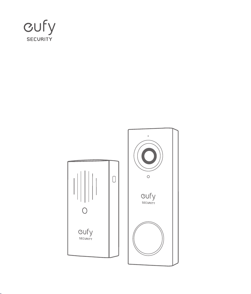
QUICK
START GUIDE
Video Doorbell 2K (Wired)

Table of Contents
What’s in the Box 01
What’s Required for Installation 02
How the System Works 02
EufySecurity App Installation 03
Video Doorbell Installation 04
Safety 15
Customer Service 17
01
English English
02
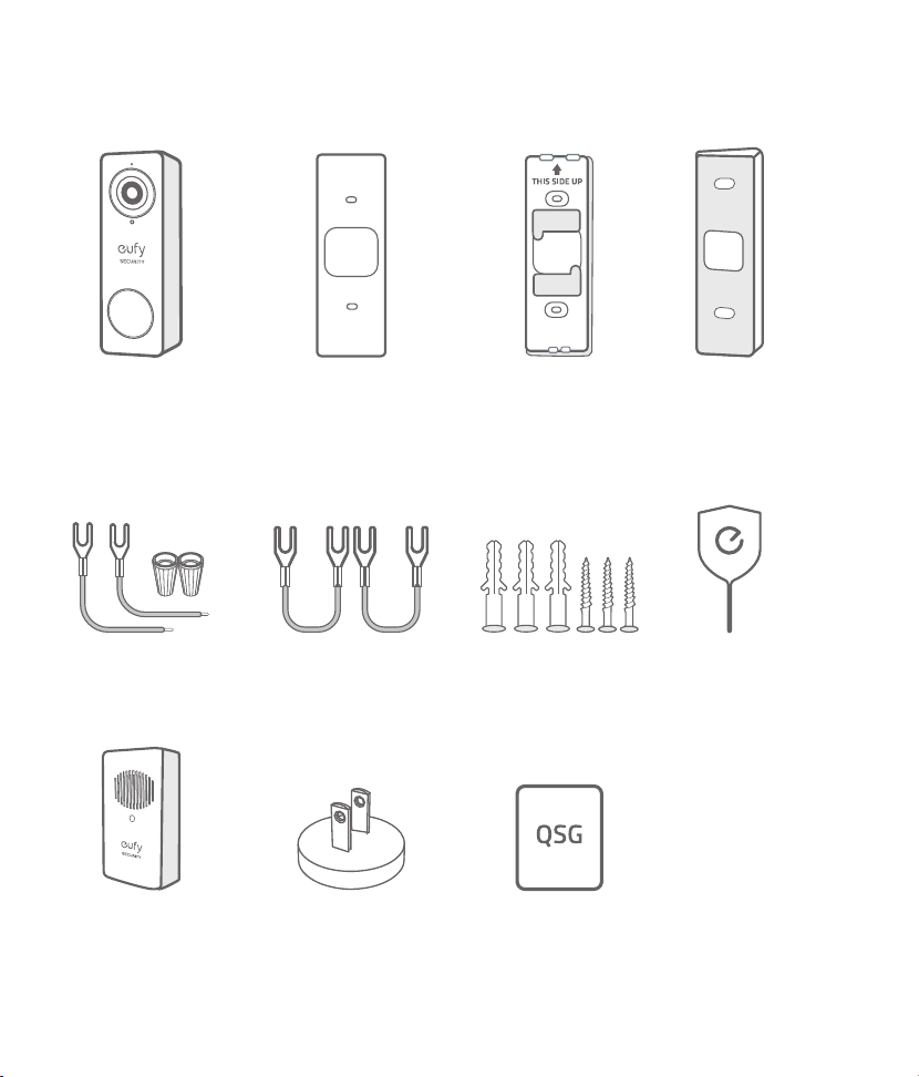
What’s in the Box
Video Doorbell 2K
(Wired)
Model: T8200
Doorbell Chime
Model: T8740
Jumper for Existing
Chime (The second one is
optional)
Extension Wires and
Wire Nuts (Optional)
Quick Start Guide
Mounting Bracket
(Attached to 15°
Mounting Wedge)
Doorbell Chime
Power connector
(The pin type may vary in
different regions
.
)
15° Mounting Wedge
(Optional)
Screw Hole
Positioning-Card
Screw Packs (Spare screws
and anchors are included
.
)
FCC ID: 2AOKB-T8200
IC: 23451-T8200
Doorbell
Detaching Pin
What’s Required for Installation
Phillips-Head Screwdriver
Power Drill with 1/4" (6.35mm) Drill Bit
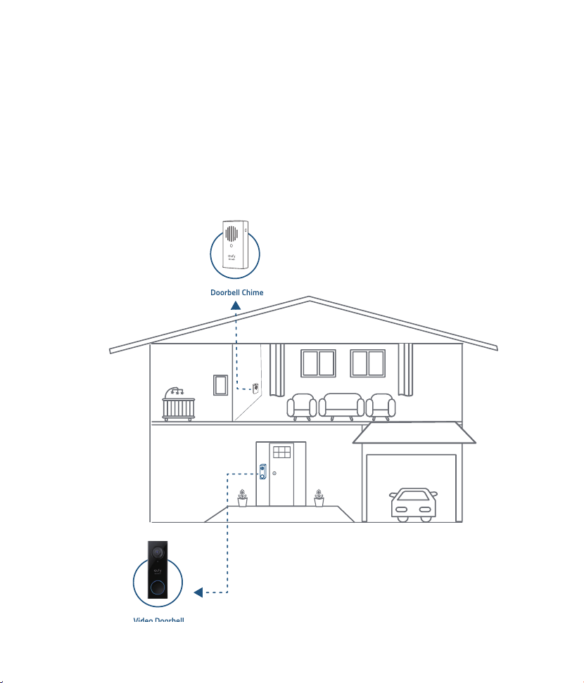
How the System Works
The Video Doorbell system includes 2 parts. One is the video doorbell at your porch. The other is the
electronic chime plugged on indoor power socket. The video doorbell is powered by existing doorbell
wires. In order to get sufficient power from the doorbell circuit, user needs to bypass the existing
doorbell chime on the circuit.
01
English English
02
What’s in the Box
Video Doorbell 2K
(Wired)
Model: T8200
Doorbell Chime
Model: T8740
Jumper for Existing
Chime (The second one is
optional)
Extension Wires and
Wire Nuts (Optional)
Quick Start Guide
Mounting Bracket
(Attached to 15°
Mounting Wedge)
Doorbell Chime
Power connector
(The pin type may vary in
different regions
.
)
15° Mounting Wedge
(Optional)
Screw Hole
Positioning-Card
Screw Packs (Spare screws
and anchors are included
.
)
FCC ID: 2AOKB-T8200
IC: 23451-T8200
Doorbell
Detaching Pin
What’s Required for Installation
Phillips-Head Screwdriver
Power Drill with 1/4" (6.35mm) Drill Bit
How the System Works
The Video Doorbell system includes 2 parts. One is the video doorbell at your porch. The other is the
electronic chime plugged on indoor power socket. The video doorbell is powered by existing doorbell
wires. In order to get sufficient power from the doorbell circuit, user needs to bypass the existing
doorbell chime on the circuit.
03
English English
04
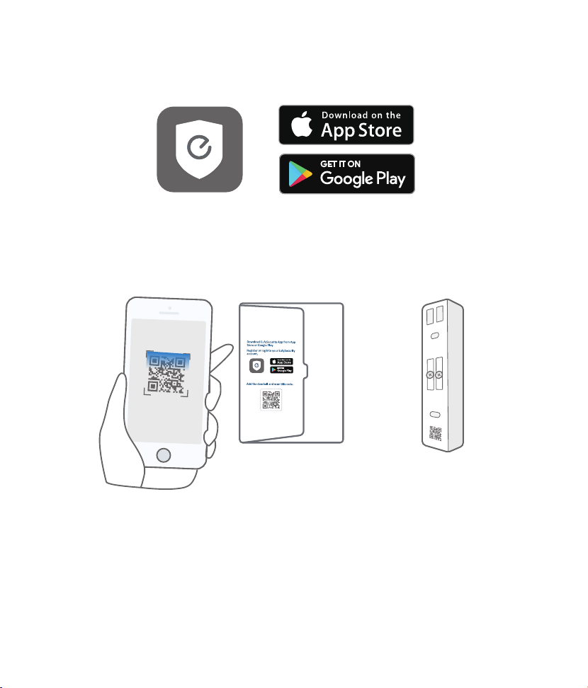
EufySecurity App Installation
Search keyword "
EufySecurity
" on App Store or Google Play and install the App on your phone.
Register and login to the App. Add video doorbell and scan the QR code for later installation process.
The QR code can be found on the back of the documentation folder or on the back of the video
doorbell.
Tips:
Follow these steps to complete the setup on the eufy Security Video Doorbell
.
Step 1. Scan the QR Code.
Step 2. Physical installation.
Step 3. Go to the App and finish the system setup.
Video Doorbell Installation
Note: Make sure you have installed the EufySecurity App and scan the QR code before start
handling the doorbell installation.
Step 1
Ring the existing doorbell, make sure it’s working and locate the place of your existing chimes in the
house.
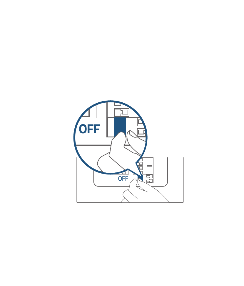
Step 2
Shut off the doorbell power supply. If you're not sure, shut off the main power supply in your house.
Turn the lights in your home on / off to make sure the electricity in your house is properly shut off.
Note: Always be careful when handling electricity wiring. If you’re not comfortable to do it yourself,
do consult a qualified electrician.
03
English English
04
EufySecurity App Installation
Search keyword "
EufySecurity
" on App Store or Google Play and install the App on your phone.
Register and login to the App. Add video doorbell and scan the QR code for later installation process.
The QR code can be found on the back of the documentation folder or on the back of the video
doorbell.
Tips:
Follow these steps to complete the setup on the eufy Security Video Doorbell
.
Step 1. Scan the QR Code.
Step 2. Physical installation.
Step 3. Go to the App and finish the system setup.
Video Doorbell Installation
Note: Make sure you have installed the EufySecurity App and scan the QR code before start
handling the doorbell installation.
Step 1
Ring the existing doorbell, make sure it’s working and locate the place of your existing chimes in the
house.
Step 2
Shut off the doorbell power supply. If you're not sure, shut off the main power supply in your house.
Turn the lights in your home on / off to make sure the electricity in your house is properly shut off.
Note: Always be careful when handling electricity wiring. If you’re not comfortable to do it yourself,
do consult a qualified electrician.
05
English English
06
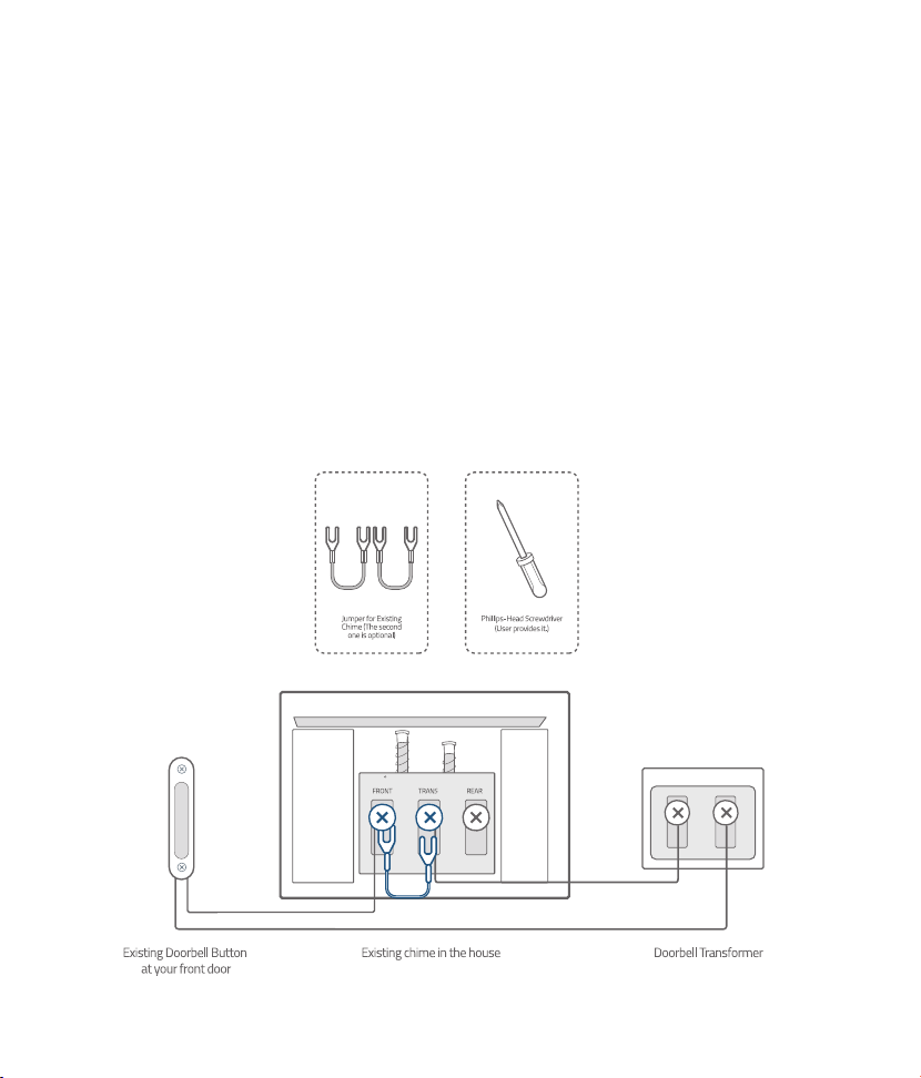
Step 3
Find the doorbell chime in your house, then remove the cover and find the screw terminals with
TRANS
and
FRONT
markings. Use the provided
jumper for existing chime
to connect the two terminals. This is
to bypass the doorbell chime and will not affect the normal operation of the circuit.
Note:
•
The video doorbell requires user to bypass the existing chime first to get sufficient power.
Without this step, the video doorbell will still be able to power on but will operate unstably
.
•
In most cases, the existing doorbell circuit looks like below chart. Find the existing doorbell
chime in your house, remove the cover and take a photo of the wire connection in case you
need to reconnect it.
•
Use the provided jumper to connect FRONT and TRANS terminals to bypass the chime on the
circuit. Do not remove the original wire connecting to the chime.
If your doorbell chime has
different markings or you have multiple chimes, refer to the help session in the App for the
custom wiring instructions or consult a qualified electrician
.
•
When the jumper is in place, the existing chime will not sound anymore
.
What are required: Jumper for existing chime / Phillips-Head Screwdriver
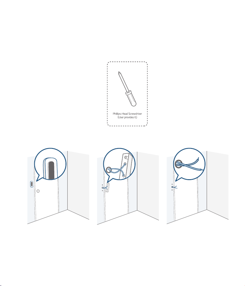
Step 4
Remove the existing doorbell button at the front door. Pull the two wires out carefully when removing
the old doorbell. Straighten the wire ends if necessary.
What's required: Phillips-Head Screwdriver
05
English English
06
Step 3
Find the doorbell chime in your house, then remove the cover and find the screw terminals with
TRANS
and
FRONT
markings. Use the provided
jumper for existing chime
to connect the two terminals. This is
to bypass the doorbell chime and will not affect the normal operation of the circuit.
Note:
•
The video doorbell requires user to bypass the existing chime first to get sufficient power.
Without this step, the video doorbell will still be able to power on but will operate unstably
.
•
In most cases, the existing doorbell circuit looks like below chart. Find the existing doorbell
chime in your house, remove the cover and take a photo of the wire connection in case you
need to reconnect it.
•
Use the provided jumper to connect FRONT and TRANS terminals to bypass the chime on the
circuit. Do not remove the original wire connecting to the chime.
If your doorbell chime has
different markings or you have multiple chimes, refer to the help session in the App for the
custom wiring instructions or consult a qualified electrician
.
•
When the jumper is in place, the existing chime will not sound anymore
.
What are required: Jumper for existing chime / Phillips-Head Screwdriver
Step 4
Remove the existing doorbell button at the front door. Pull the two wires out carefully when removing
the old doorbell. Straighten the wire ends if necessary.
What's required: Phillips-Head Screwdriver
07
English English
08
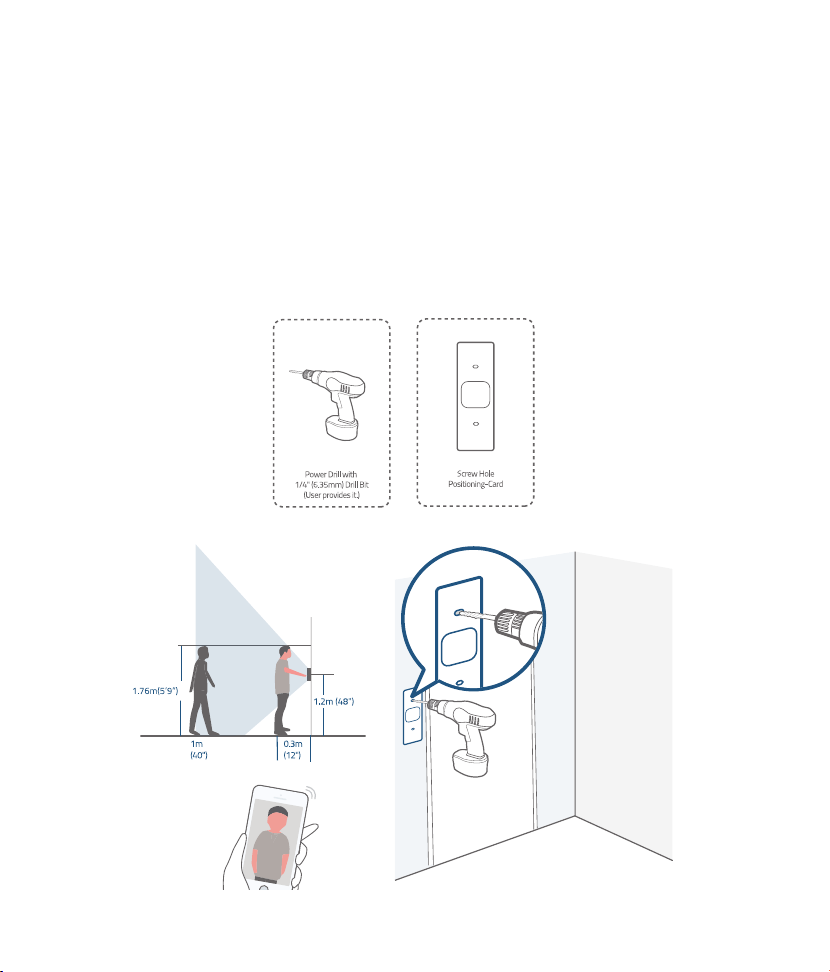
Step 5
Determine the mounting position of the doorbell. Consider the below factors:
1. Check if you can reuse the existing holes and anchors on the wall or door frame.
2. If you are drilling the mounting holes for the first time the recommended mounting height is 48"
from the ground.
If you are mounting the doorbell on a wooden wall or board, do NOT drill holes. Skip to Step7 and
use screws directly to mount the Mounting Bracket.
If your wall is stucco, brick or concrete, you need to drill holes. Use the Screw Hole Positioning-Card
to mark the position and drill holes with 1/4" (6.35mm) drill bit.
What are required: Power Drill with 1/4" (6.35mm) Drill Bit / Screw Hole Positioning-Card
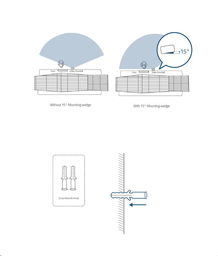
Optional: Use the 15° mounting wedge as a supplementary mounting bracket if you wish to see
more on a specific side.
Step 6
Use the anchors provided when installing in materials such as stucco, brick, or concrete. There is no
need to use anchor If you were installing on wooden doorframe.
What's required: Anchors
07
English English
08
Step 5
Determine the mounting position of the doorbell. Consider the below factors:
1. Check if you can reuse the existing holes and anchors on the wall or door frame.
2. If you are drilling the mounting holes for the first time the recommended mounting height is 48"
from the ground.
If you are mounting the doorbell on a wooden wall or board, do NOT drill holes. Skip to Step7 and
use screws directly to mount the Mounting Bracket.
If your wall is stucco, brick or concrete, you need to drill holes. Use the Screw Hole Positioning-Card
to mark the position and drill holes with 1/4" (6.35mm) drill bit.
What are required: Power Drill with 1/4" (6.35mm) Drill Bit / Screw Hole Positioning-Card
Optional: Use the 15° mounting wedge as a supplementary mounting bracket if you wish to see
more on a specific side.
Step 6
Use the anchors provided when installing in materials such as stucco, brick, or concrete. There is no
need to use anchor If you were installing on wooden doorframe.
What's required: Anchors
09
English English
10
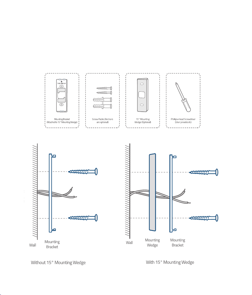
Step 7
Lead the two doorbell wires through the central square hole on the bracket before start mounting.
Insert the two screws provided through the screw holes or through the 15° mounting wedge(Install
the mounting bracket to the 15° mounting wedge in prior), and fasten the screws tightly.
What are required: Mounting Bracket / Screw Packs / 15° Mounting Wedge(Optional) / Phillips-
Head Screwdriver
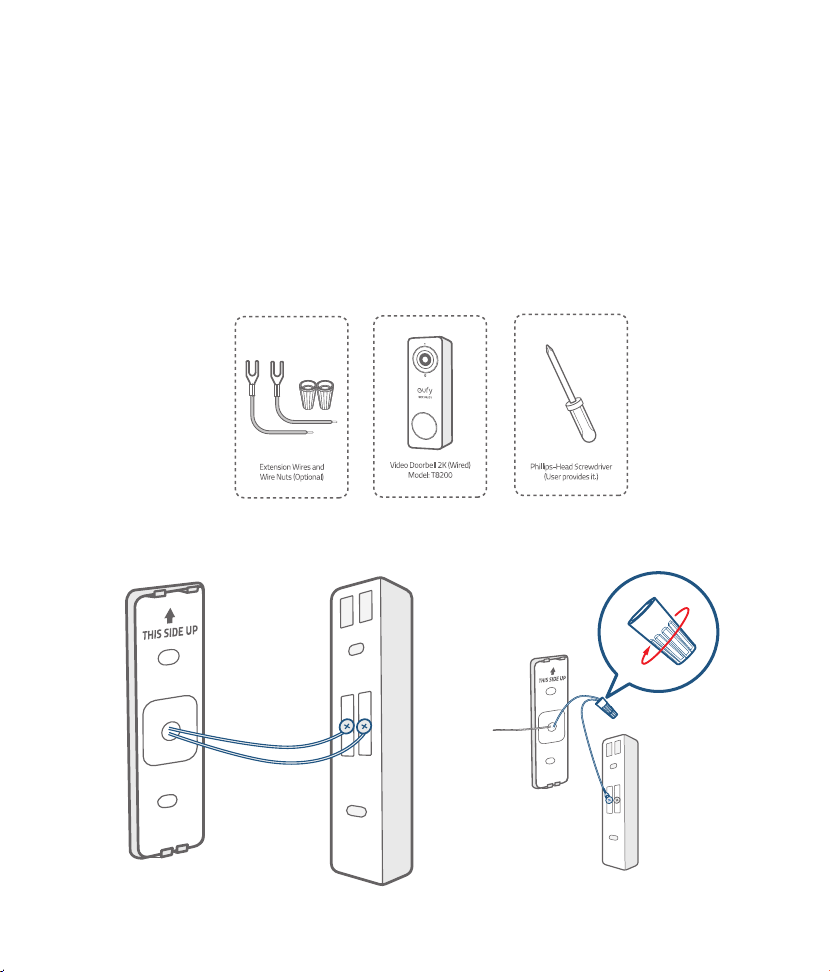
Step 8
Connect the wires to the two terminals at the back of the doorbell, then tighten the terminal screws.
Wire can connect to any terminal as the electric current is alternating current.
Note: To prevent short-circuit, make sure the wires are not touching each other after connecting
them to the terminals. If the wires are too short, use the extension wires and wire nuts provided to
make them longer. Use electrical wiring tape to secure the connection if the wall doesn't have space
for wire nuts.
What are required: Extension Wires and Wire Nuts (Optional) / Video doorbell / Philips-Head
Screwdriver
09
English English
10
Step 7
Lead the two doorbell wires through the central square hole on the bracket before start mounting.
Insert the two screws provided through the screw holes or through the 15° mounting wedge(Install
the mounting bracket to the 15° mounting wedge in prior), and fasten the screws tightly.
What are required: Mounting Bracket / Screw Packs / 15° Mounting Wedge(Optional) / Phillips-
Head Screwdriver
Step 8
Connect the wires to the two terminals at the back of the doorbell, then tighten the terminal screws.
Wire can connect to any terminal as the electric current is alternating current.
Note: To prevent short-circuit, make sure the wires are not touching each other after connecting
them to the terminals. If the wires are too short, use the extension wires and wire nuts provided to
make them longer. Use electrical wiring tape to secure the connection if the wall doesn't have space
for wire nuts.
What are required: Extension Wires and Wire Nuts (Optional) / Video doorbell / Philips-Head
Screwdriver
11
English English
12
Step 9
There are 2 thermal conductive pads on the mounting bracket. They're used to conduct heat from
video doorbell to the metal bracket. Remove the films on the thermal conductive pads before you
mount the doorbell.
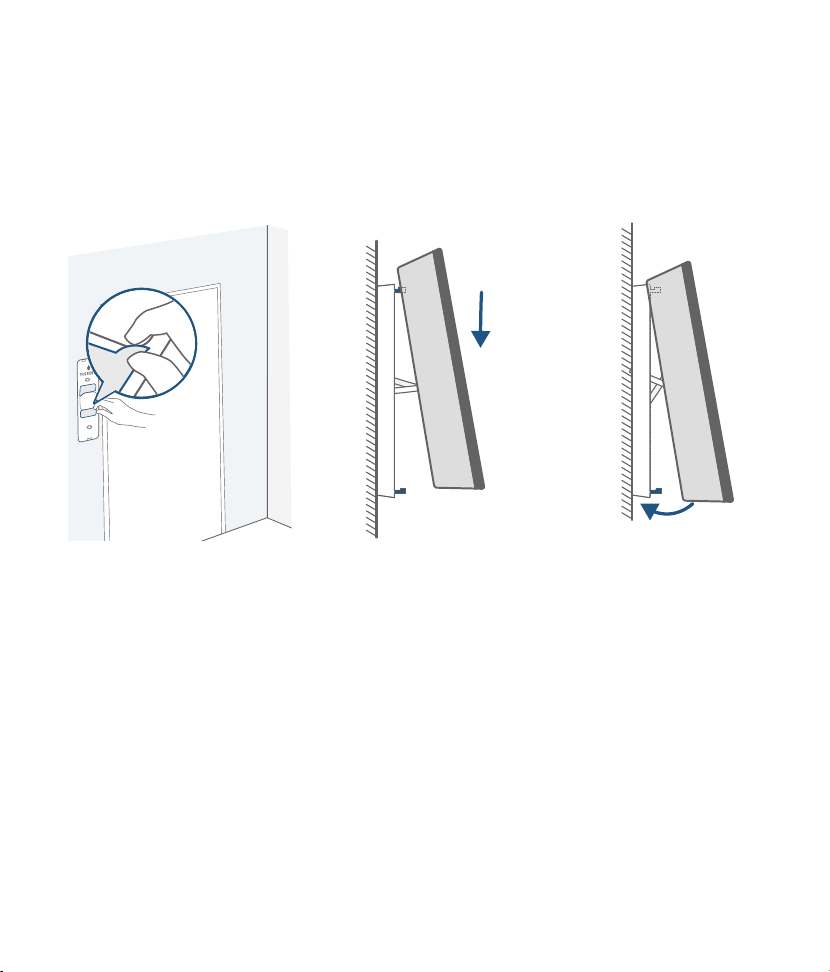
Hook the doorbell on top of the mounting bracket and then snap the doorbell bottom to the bracket.
You may hear a "click" sound.
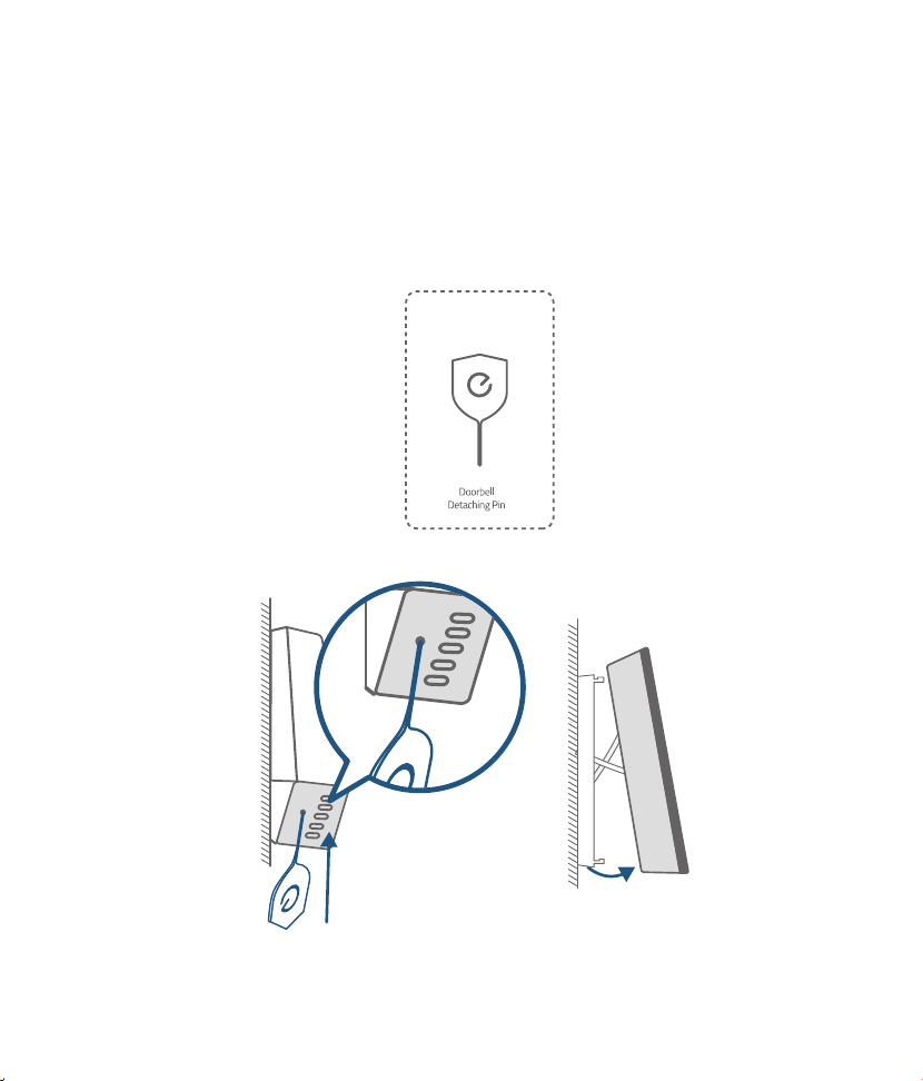
Use the doorbell detaching pin provided if you wish to detach the doorbell from the mounting Bracket.
Press and hold the hole on the bottom of the doorbell and then lift its bottom to take it off.
The detaching pin has magnet pad on the black-color side. Stick it on iron surface where you can find
it easily.
Note: The oval holes are speaker holes. Only press the round hole to detach the doorbell.
What's required: Doorbell detaching pin
11
English English
12
Step 9
There are 2 thermal conductive pads on the mounting bracket. They're used to conduct heat from
video doorbell to the metal bracket. Remove the films on the thermal conductive pads before you
mount the doorbell.
Hook the doorbell on top of the mounting bracket and then snap the doorbell bottom to the bracket.
You may hear a "click" sound.
Use the doorbell detaching pin provided if you wish to detach the doorbell from the mounting Bracket.
Press and hold the hole on the bottom of the doorbell and then lift its bottom to take it off.
The detaching pin has magnet pad on the black-color side. Stick it on iron surface where you can find
it easily.
Note: The oval holes are speaker holes. Only press the round hole to detach the doorbell.
What's required: Doorbell detaching pin
13
English English
14
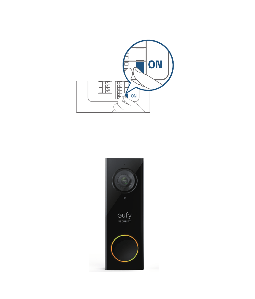
Step 10
Switch the doorbell or master circuit breaker to ON.
Step 11
Wait until the doorbell ring flashes yellow. Then follow the on-screen instructions in EufySecurity App
to connect the video doorbell to your home Wi-Fi.
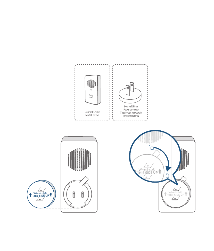
Step 12
Follow the on-screen instructions in EufySecurity App. Install the doorbell power connector to the
doorbell chime and then pair it to your video doorbell.
Note: One video doorbell can link up to 4 electronic chimes. Use the volume and music buttons on the
side of the electronic chime to adjust the volume and ringtone.
What are required: Doorbell chime / Doorbell chime power connector
13
English English
14
Step 10
Switch the doorbell or master circuit breaker to ON.
Step 11
Wait until the doorbell ring flashes yellow. Then follow the on-screen instructions in EufySecurity App
to connect the video doorbell to your home Wi-Fi.
Step 12
Follow the on-screen instructions in EufySecurity App. Install the doorbell power connector to the
doorbell chime and then pair it to your video doorbell.
Note: One video doorbell can link up to 4 electronic chimes. Use the volume and music buttons on the
side of the electronic chime to adjust the volume and ringtone.
What are required: Doorbell chime / Doorbell chime power connector

15
English English
16
Safety
FCC Statement
This device complies with Part 15 of the FCC Rules. Operation is subject to the following two conditions: (1)
this device may not cause harmful interference, and (2) this device must accept any interference received,
including interference that may cause undesired operation.
Warning:
Changes or modifications not expressly approved by the party responsible for compliance could
void the user's authority to operate the equipment.
Note:
This equipment has been tested and found to comply with the limits for a Class B digital device,
pursuant to Part 15 of the FCC Rules. These limits are designed to provide reasonable protection against
harmful interference in a residential installation.
This equipment generates uses and can radiate radio frequency energy and, if not installed and used in
accordance with the instructions, may cause harmful interference to radio communications. However, there
is no guarantee that interference will not occur in a particular installation. If this equipment does cause
harmful interference to radio or television reception, which can be determined by turning the equipment off
and on, the user is encouraged to try to correct the interference by one or more of the following measures: (1)
Reorient or relocate the receiving antenna. (2) Increase the separation between the equipment and receiver.
(3) Connect the equipment into an outlet on a circuit different from that to which the receiver is connected. (4)
Consult the dealer or an experienced radio/TV technician for help.
FCC Radio Frequency Exposure Statement
The device has been evaluated to meet general RF exposure requirements. The device can be used in fixed/
mobile exposure condition. The min separation distance is 20cm.
Notice:
Shielded cables
All connections to other computing devices must be made using shielded cables to maintain compliance with
FCC regulations.
The following importer is the responsible party
Company Name: POWER MOBILE LIFE, LLC
Address: 400 108th Ave NE Ste 400, Bellevue, WA 98004-5541
Telephone:1-800-988-7973、
This product complies with the radio interference requirements of the European Community.
Declaration of Conformity
Hereby, Anker Innovations Limited declares that this device is in compliance with the essential requirements
and other relevant provisions of Directive 2014/53/EU.For the declaration of conformity, visit the Web site
www.eufylife.com
Do not use the Device in the environment at too high or too low temperature, never expose the Device under
strong sunshine or too wet environment.
The suitable temperature for T8200 is -20°C-50°C.
The suitable temperature for T8740 is 0°C-45°C.
RF exposure information: The Maximum Permissible Exposure (MPE) level has been calculated based on a
distance of d=20 cm between the device and the human body. To maintain compliance with RF exposure
requirement, use product that maintain a 20cm distance between the device and human body.
CAUTION RISK OF EXPLOSION IF BATTERY IS REPLACED BY AN INCORRECT TYPE. DISPOSE OF USED
BATTERIES ACCORDING TO THE INSTRUCTIONS
Wi-Fi Operating Frequency Range: 2412~2472MHz for EU;
Wifi Max Output Power:19dBm
Bluetooth Operating Frequency Range:2402~2480MHz; Bluetooth Max Output Power:8dBm
433MHz Frequency Range:433.92MHZ;433MHz Max Output Power:10dBm
The following importer is the responsible party (contact for EU matters only)
Importer:Anker Technology (UK) Ltd
Importer Address:Suite B, Fairgate House, 205 Kings Road, Tyseley, Birmingham, B11 2AA, United Kingdom
This product is designed and manufactured with high quality materials and components, which can
be recycled and reused.
This symbol means the product must not be discarded as household waste, and should be delivered
to an appropriate collection facility for recycling. Proper disposal and recycling helps protect natural
resources, human health and the environment. For more information on disposal and recycling of
this product, contact your local municipality, disposal service, or the shop where you bought this
product.This device complies with Industry Canada licence-exempt RSS standard(s). Operation is
subject to the following two conditions:
(1) this device may not cause interference, and
(2) this device must accept any interference, including interference that may cause undesired operation of
the device."
Le présent appareil est conforme aux CNR d'Industrie Canada applicables aux appareils radio exempts de
licence. L'exploitation est autorisée aux deux conditions suivantes:
(1) l'appareil nedoit pas produire de brouillage, et
(2) l'utilisateur de l'appareil doit accepter tout brouillage radioélectrique subi, même si le brouillage est
susceptible d'en compromettre le fonctionnement."
Please note that your rights under applicable law governing the sale of consumer goods remain unaffected
by the warranties given in this Limited Warranty.
This Class B digital apparatus complies with Canadian ICES-003.
Cet appareil numérique de la classe B est conforme à la norme NMB-003 du Canada.
IC RF Statement:
When using the product, maintain a distance of 20cm from the body to ensure compliance with RF exposure
requirements.
Lors de l'utilisation du produit, maintenez une distance de 20 cm du corps afin de vous conformer aux
exigences en matière d'exposition RF.

17
English
Customer Service
• Warranty
12-month limited warranty
• Call Us
United States +1 (800) 988 7973 Mon-Fri 9AM-5PM (PT)
United Kingdom +44 (0) 1604 936 200 Mon-Fri 6AM-11AM (GMT)
Germany +49 (0) 69 9579 7960 Mon-Fri 6:00-11:00
• Email Us
Customer Support: [email protected]
Anker Innovations Limited
Room 1318-19, Hollywood Plaza, 610 Nathan Road, Mongkok, Kowloon, Hong Kong

Anker Innovations Limited. All rights reserved.
eufy Security and eufy Security Logo
are trademarks of Anker Innovations Limited, registered in the United States and other
countries. All other trademarks are the property of their respective owners.
51005002211 V03
QUICK
START GUIDE
Video Doorbell 2K (Wired)
