
Anker Innovations Limited. All rights reserved. eufy Security and eufy Security Logo
are trademarks of Anker Innovations Limited, registered in the United States and
other countries. All other trademarks are the property of their respective owners.
T8530 51005003294 V01
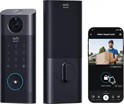
Video Smart Lock
QUICK START GUID
E
Anker Innovations Limited. All rights reserved. eufy Security and eufy Security Logo
are trademarks of Anker Innovations Limited, registered in the United States and
other countries. All other trademarks are the property of their respective owners.
T8530 51005003294 V01
Video Smart Lock
QUICK START GUID
E
01 EN
EN 02
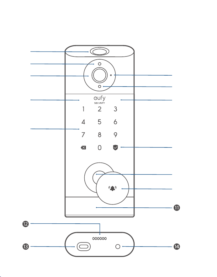
Fingerprint Scanner: Use to lock and unlock the door.
Battery Indicator: Turns red when the battery is low.
Camera Lens
Microphone
Ambient Light Sensor: Detects the amount of light.
IR LED
Keypad
Status Light & Lock and Unlock Button: Press and hold to lock
the door.
Blue: Door unlocked.
Orange: Door locked.
Red: Abnormal status detected.
Lock Cylinder
Doorbell Button: The ring light automatically turns on when
someone
approaches the door.
Motion Sensor
Speaker
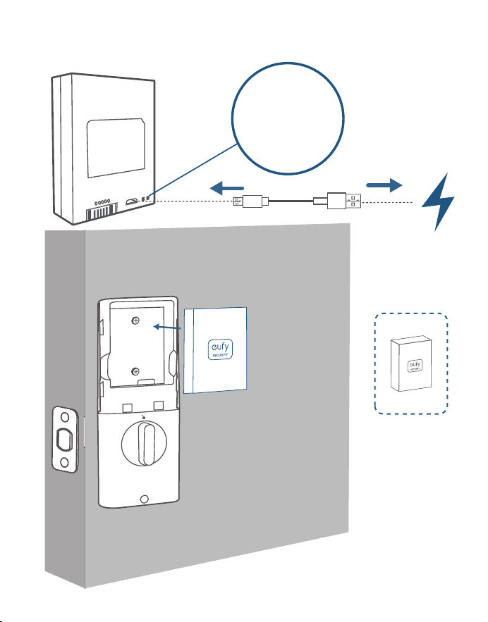
USB-C Port: Charges the lock in emergency situations.
Reboot Button: Reboots the lock.
OVERVIEW
❷
❶
❸
❻
❼
❹
❺
❽
❻
❾
❿
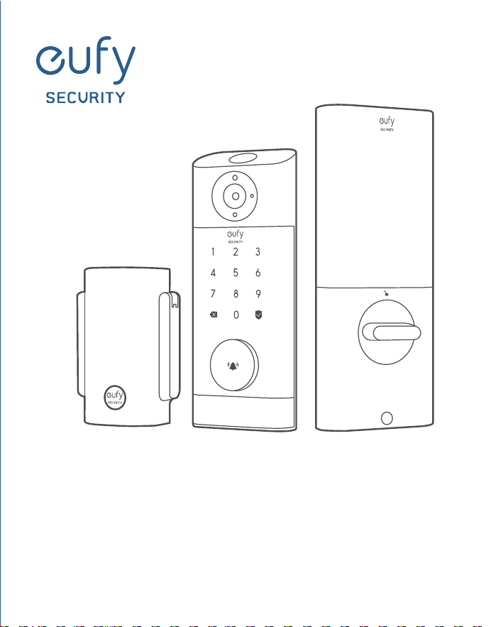
eufy Security Video Smart Lock
Model: T8530

01 EN
EN 02
Fingerprint Scanner: Use to lock and unlock the door.
Battery Indicator: Turns red when the battery is low.
Camera Lens
Microphone
Ambient Light Sensor: Detects the amount of light.
IR LED
Keypad
Status Light & Lock and Unlock Button: Press and hold to lock
the door.
Blue: Door unlocked.
Orange: Door locked.
Red: Abnormal status detected.
Lock Cylinder
Doorbell Button: The ring light automatically turns on when
someone
approaches the door.
Motion Sensor
Speaker
USB-C Port: Charges the lock in emergency situations.
Reboot Button: Reboots the lock.
OVERVIEW
❷
❶
❸
❻
❼
❹
❺
❽
❻
❾
❿
eufy Security Video Smart Lock
Model: T8530

03 EN
EN 04
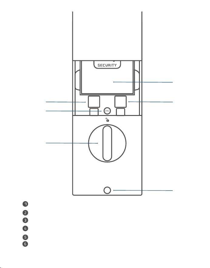
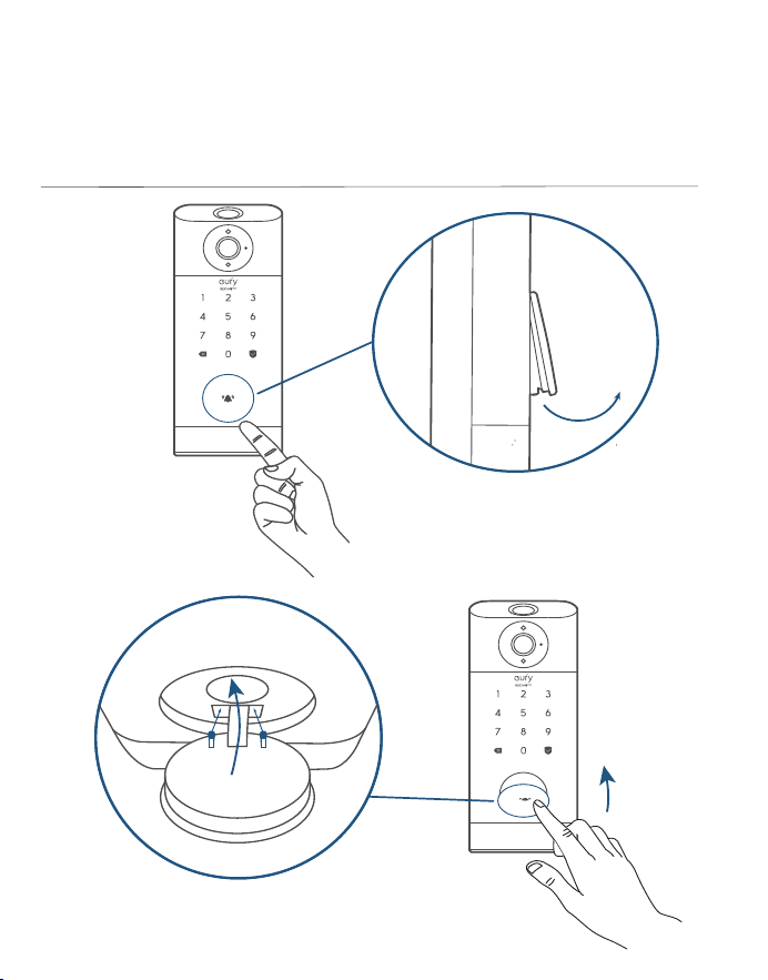
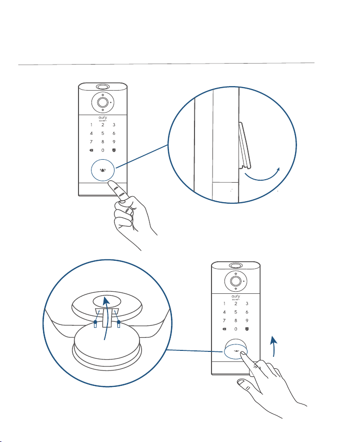
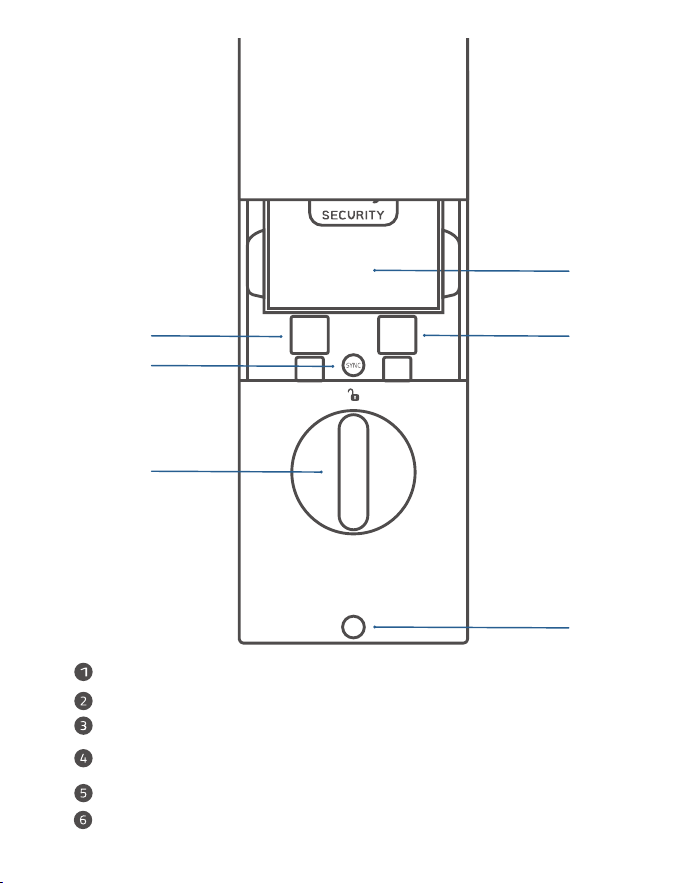
How To Open / Close Lock Cylinder Cover
❶
❷
❻
❺
❹
❸
Battery
Serial Number
QR Code
SYNC Button: Press and hold to pair with the doorbell chime.
Thumbturn
Screw Hole
03 EN
EN 04
How To Open / Close Lock Cylinder Cover
❶
❷
❻
❺
❹
❸
Battery
Serial Number
QR Code
SYNC Button: Press and hold to pair with the doorbell chime.
Thumbturn
Screw Hole
05 EN
EN 06
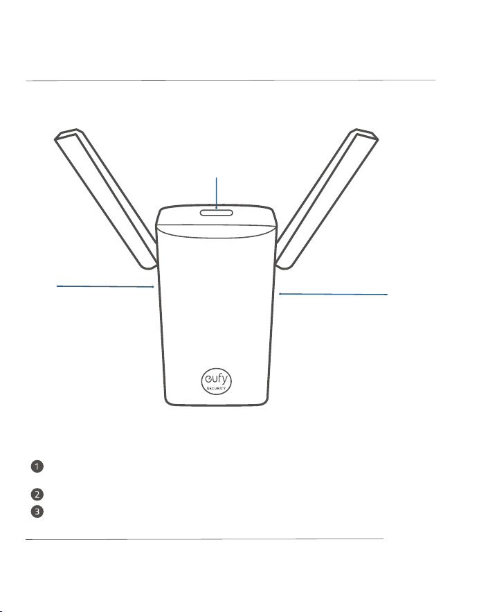
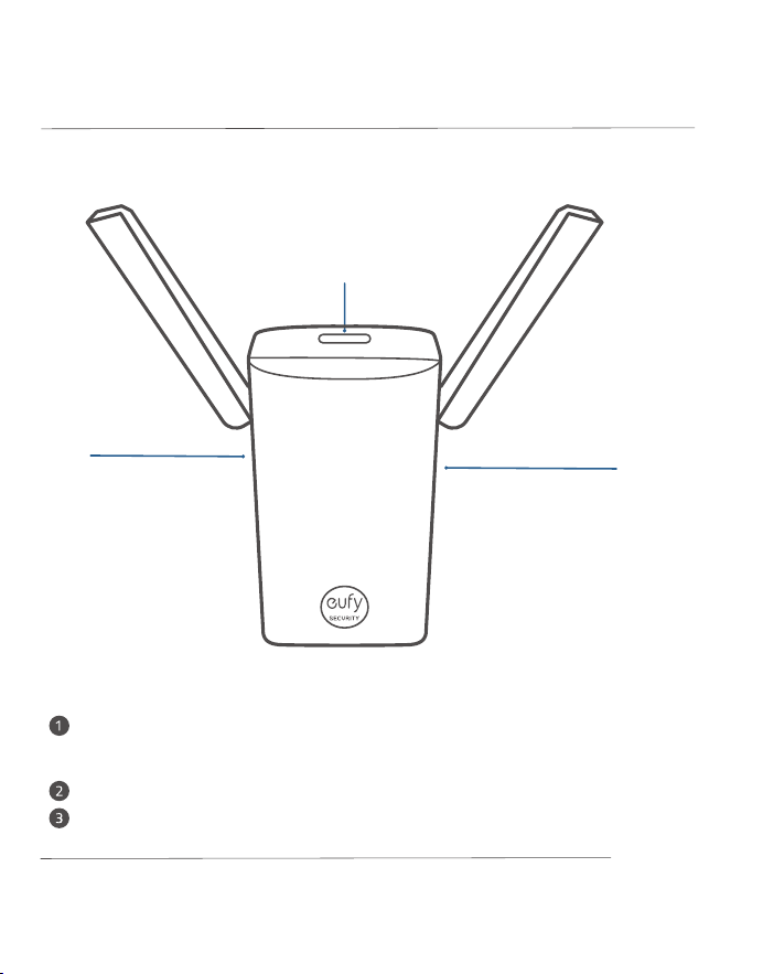
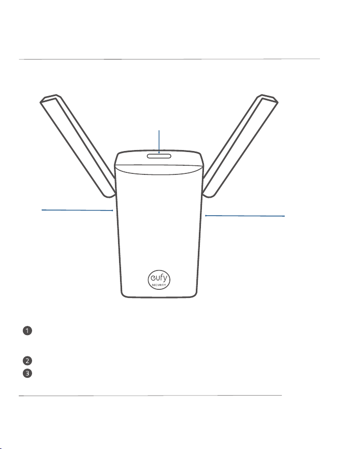
MicroSD Card Slot: To store video recordings, insert a storage card (sold
separately)
Reset Hole
SYNC Button
Wi-Fi Bridge & Doorbell Chime*
❸
❷
❶
Model: T8021
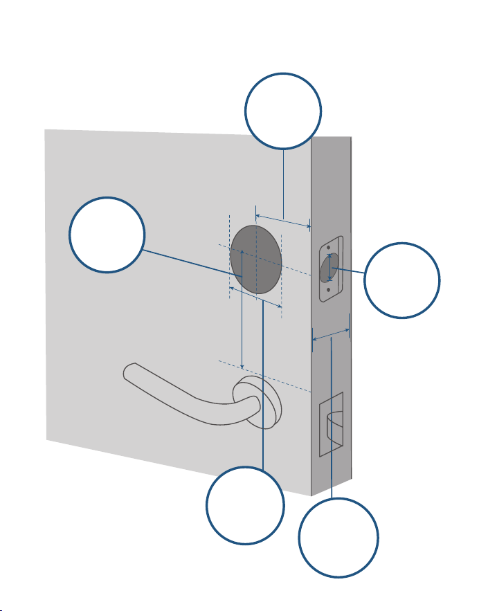
COMPATIBLE DOORS
1" / 25 mm
2⅜" / 60 mm
2⅜" / 60 mm or
2¾" / 70 mm
2 ⅛" / 54 mm
1 ½" / 38 mm
1⅜" - 2 ⅛"
35 mm-55 mm
*
Also sold as Wi-Fi bridge
Backset
Minimum
Distance
Door Hole
Diameter
Cross Bore
Diameter
Door
Thickness

05 EN
EN 06
MicroSD Card Slot: To store video recordings, insert a storage card (sold
separately)
Reset Hole
SYNC Button
Wi-Fi Bridge & Doorbell Chime*
❸
❷
❶
Model: T8021
COMPATIBLE DOORS
1" / 25 mm
2⅜" / 60 mm
2⅜" / 60 mm or
2¾" / 70 mm
2 ⅛" / 54 mm
1 ½" / 38 mm
1⅜" - 2 ⅛"
35 mm-55 mm
*
Also sold as Wi-Fi bridge
Backset
Minimum
Distance
Door Hole
Diameter
Cross Bore
Diameter
Door
Thickness
07 EN
EN 08
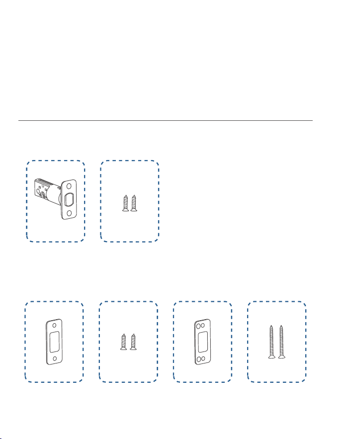
INSTALLING
VIDEO SMART LOCK
»
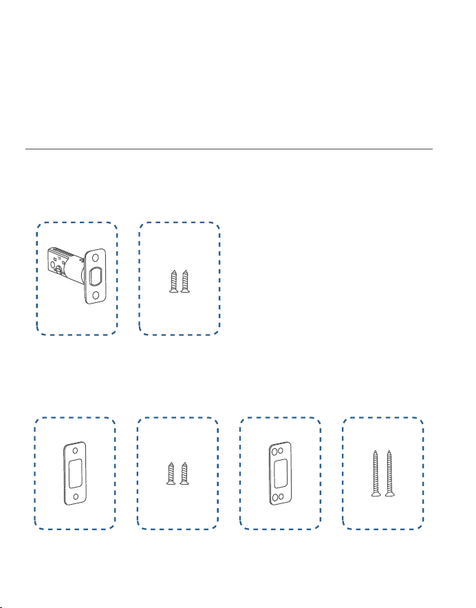
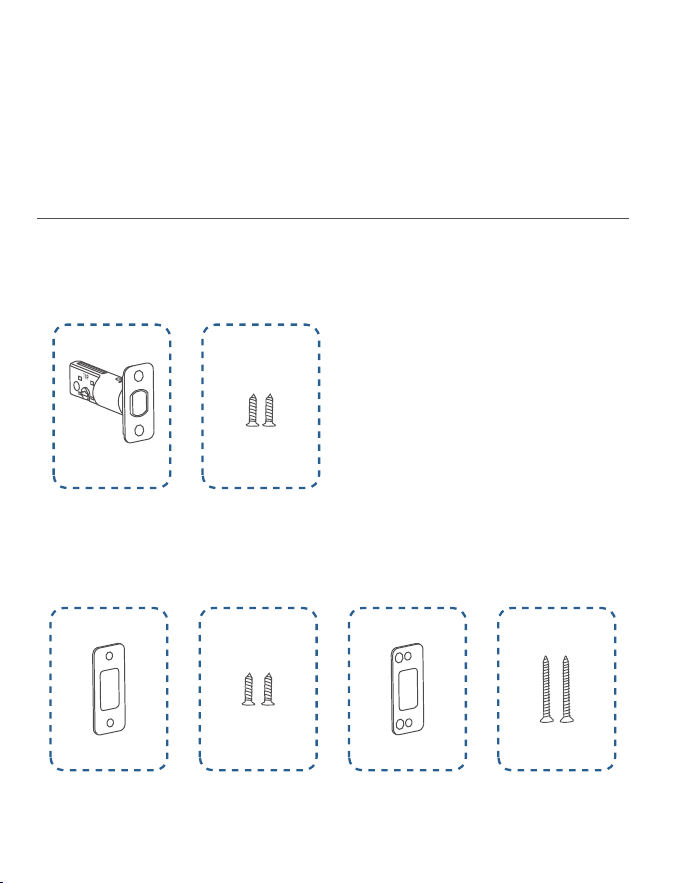
Step 1. Deadbolt Installation Set
»
Step 2. Strike Plate Installation Set
»
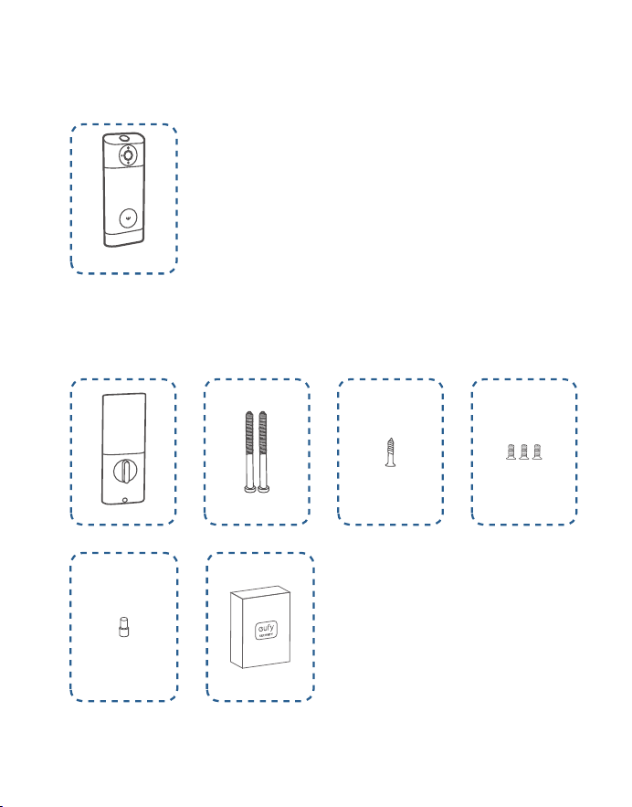
Step 3. Exterior Assembly
»
Step 4. Interior Assembly Installation Set
What You Need
A
B
C D
E F
G
H
I J K
L M

07 EN
EN 08
INSTALLING
VIDEO SMART LOCK
»
Step 1. Deadbolt Installation Set
»
Step 2. Strike Plate Installation Set
»
Step 3. Exterior Assembly
»
Step 4. Interior Assembly Installation Set
What You Need
A
B
C D
E F
G
H
I J K
L M
09 EN
EN 10
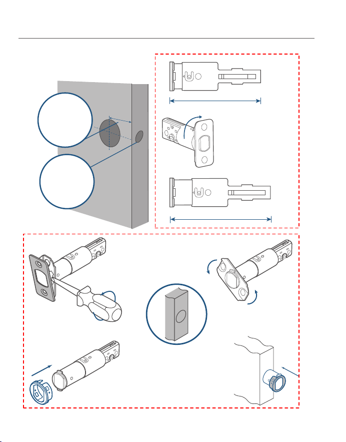
Step 1. Install Deadbolt
2-3/8
2-3/4
180°
2⅜" / 60 mm
2¾" / 70 mm
❷
❶
❸
❹
If the backset is
70 mm, turn the
faceplate 180° to
extend the length.
If the latch hole is round,
contact customer service
to receive a round drive-in
faceplate, then replace the
existing one.
1. Check your door to see if the
deadbolt requires adjuestment.
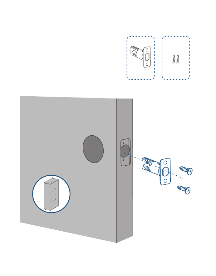
2. Insert and screw the deadbolt
into the doorframe.
A
B
Make sure the word "TOP"
on the deadbolt faces up.
Backset
Latch Hole
09 EN
EN 10
Step 1. Install Deadbolt
2-3/8
2-3/4
180°
2⅜" / 60 mm
2¾" / 70 mm
❷
❶
❸
❹
If the backset is
70 mm, turn the
faceplate 180° to
extend the length.
If the latch hole is round,
contact customer service
to receive a round drive-in
faceplate, then replace the
existing one.
1. Check your door to see if the
deadbolt requires adjuestment.
2. Insert and screw the deadbolt
into the doorframe.
A
B
Make sure the word "TOP"
on the deadbolt faces up.
Backset
Latch Hole

11 EN
EN 12
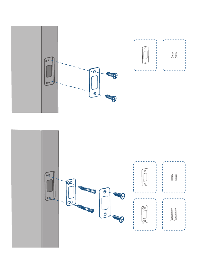
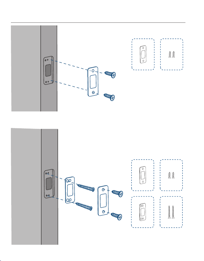
Step 2. Install Strike Plate
C D
C D
E F
Option 1
Option 2: Add the strike reinforcer for more security.
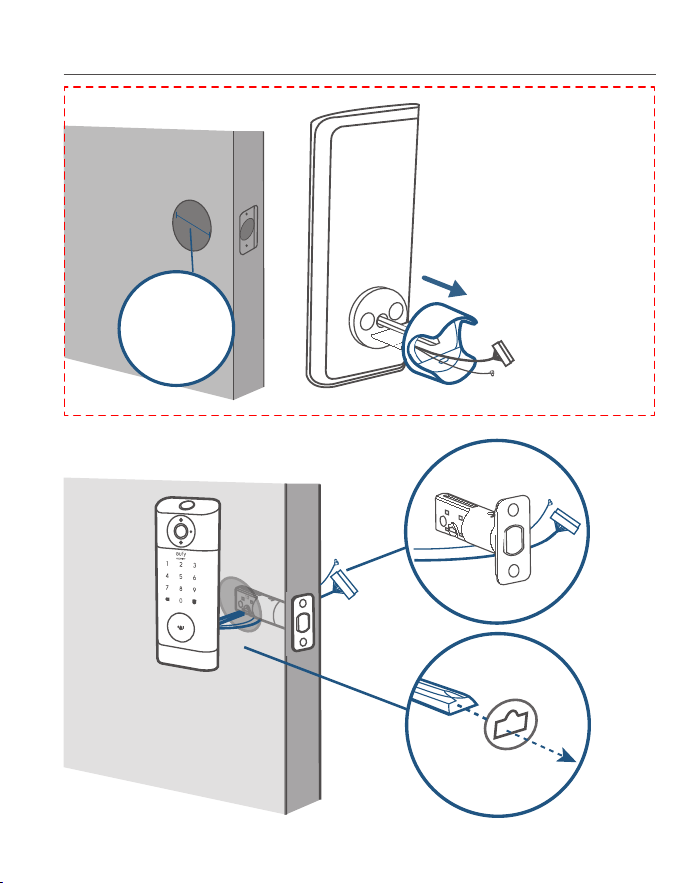
Step 3. Install Exterior Assembly
If you have a 38mm cross
bore, remove the spacer
before installation.
Cross bore
diameter
1 ½" or 38 mm
11 EN
EN 12
Step 2. Install Strike Plate
C D
C D
E F
Option 1
Option 2: Add the strike reinforcer for more security.
Step 3. Install Exterior Assembly
If you have a 38mm cross
bore, remove the spacer
before installation.
Cross bore
diameter
1 ½" or 38 mm
13 EN
EN 14
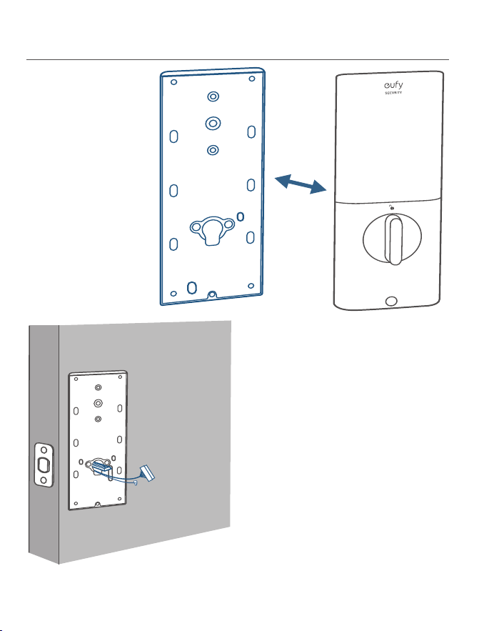
H
I
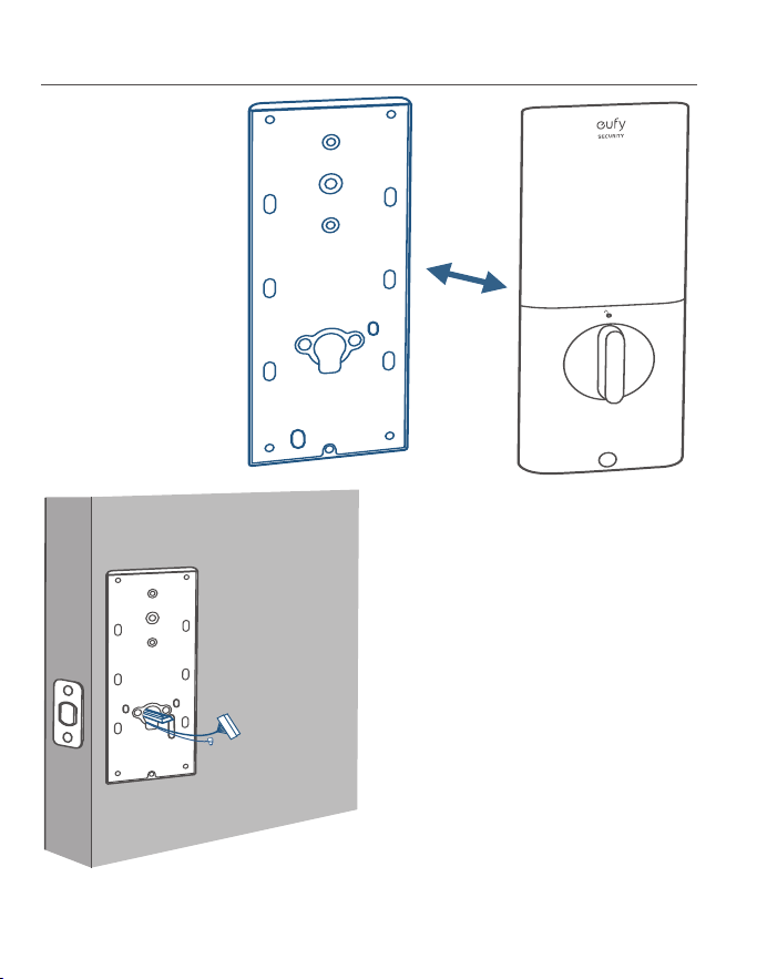
Step 4. Install Interior Assembly
1. Detach the back cover
from the interior
assembly.
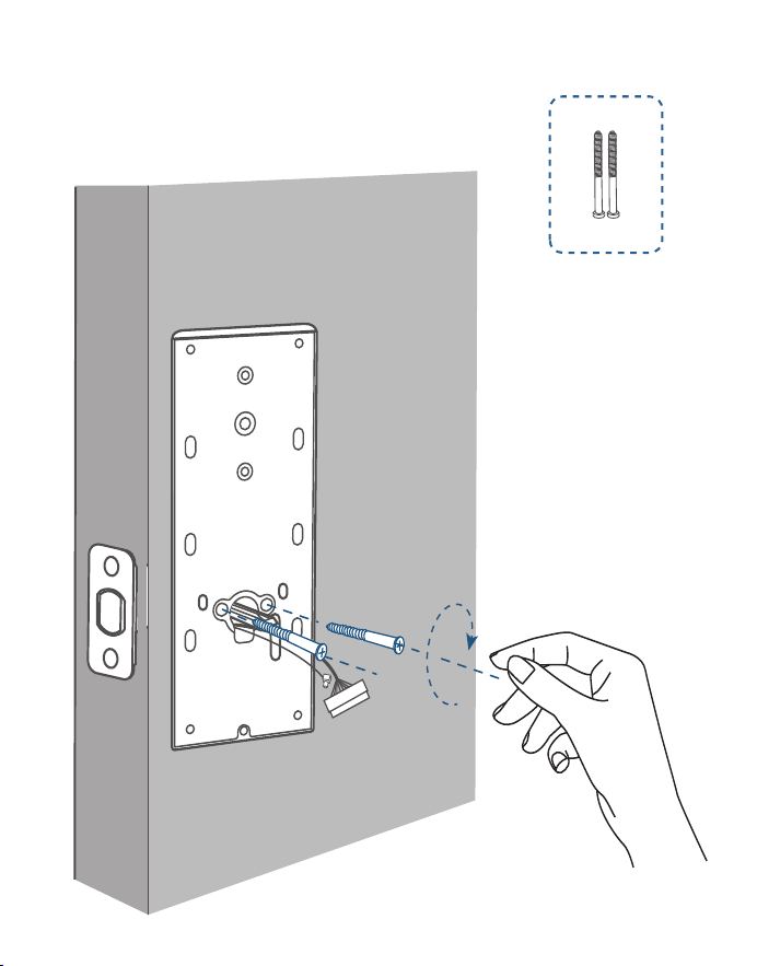
Tightly fasten the screws
in place. Set the screws
with your hands, then use
a screwdriver to secure
them.
3. Secure the back cover with screws.
I
2. Run the wires through the back
cover.
13 EN
EN 14
H
I
Step 4. Install Interior Assembly
1. Detach the back cover
from the interior
assembly.
Tightly fasten the screws
in place. Set the screws
with your hands, then use
a screwdriver to secure
them.
3. Secure the back cover with screws.
I
2. Run the wires through the back
cover.
15 EN
EN 16
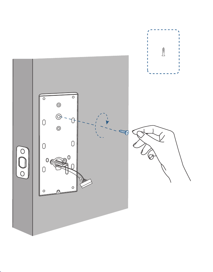
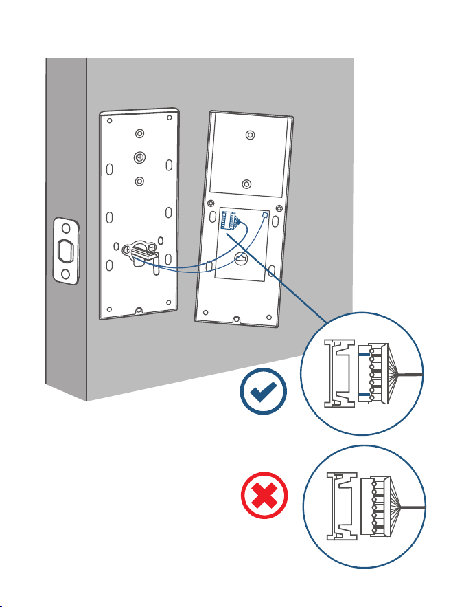
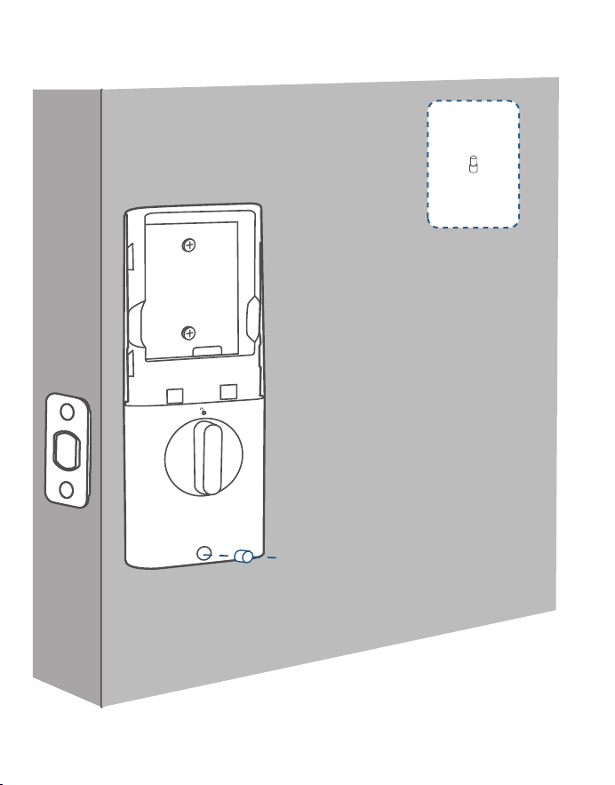
4. (Optional) If the back cover is not fastened tightly to the door, use the additional
screw provided.
J
5. Wire to the interior assembly
.
Upside Down

15 EN
EN 16
4. (Optional) If the back cover is not fastened tightly to the door, use the additional
screw provided.
J
5. Wire to the interior assembly
.
Upside Down

17 EN
EN 18
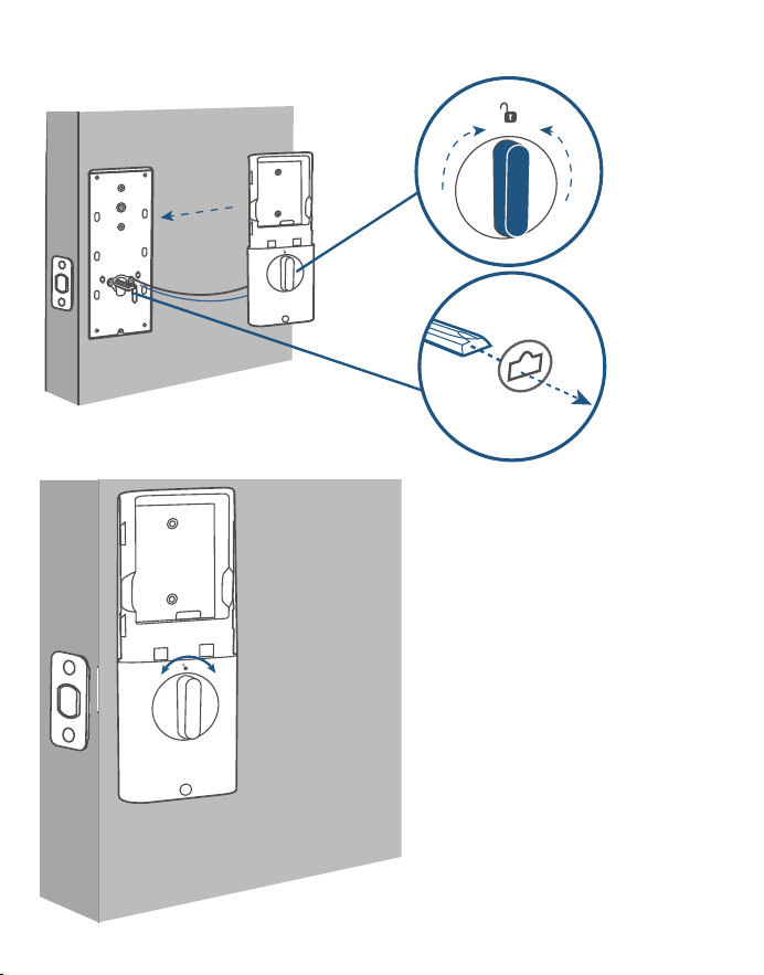
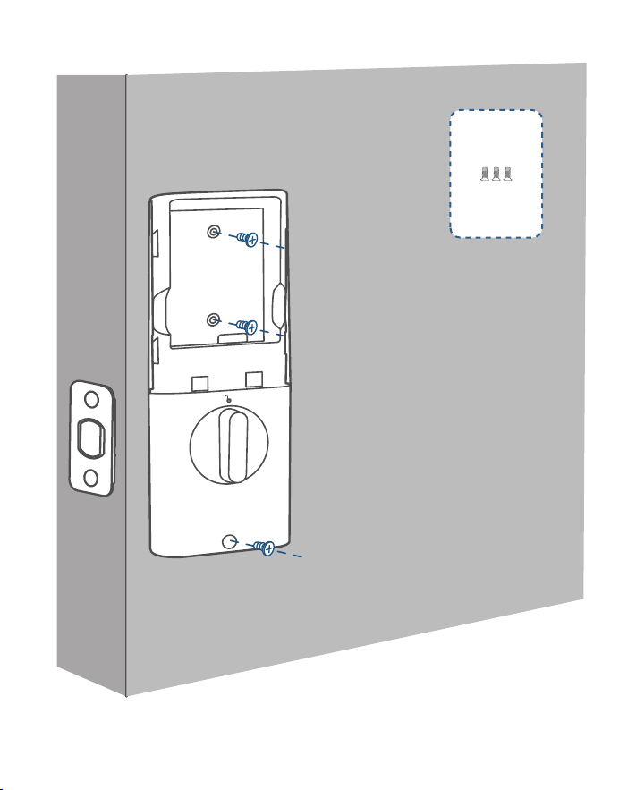
6. Mount the interior assembly. Make sure both wires are tucked into the
cabin on the back of the interior assembly.
Check if the deadbolt
retracts by turning the
thumbturn
K

17 EN
EN 18
6. Mount the interior assembly. Make sure both wires are tucked into the
cabin on the back of the interior assembly.
Check if the deadbolt
retracts by turning the
thumbturn
K

19 EN
EN 20
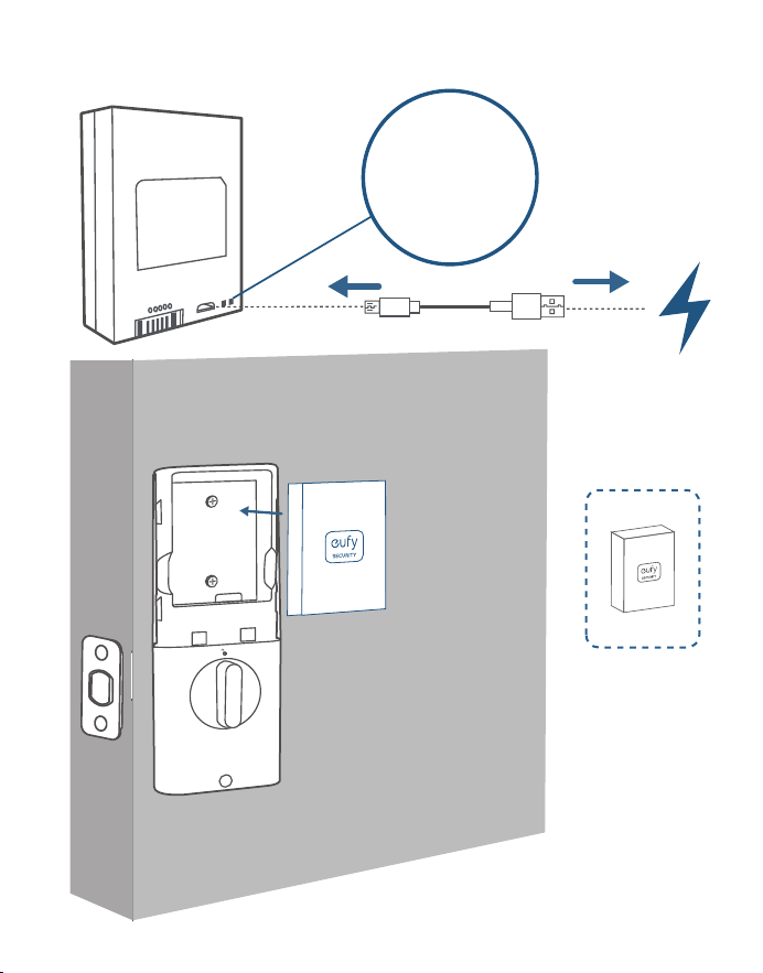
7. Fully charge the battery before first use. It might take about 6 hours.
L
M
LED Indicator
Red: Charging
Blue: Fully
Charged

19 EN
EN 20
7. Fully charge the battery before first use. It might take about 6 hours.
L
M
LED Indicator
Red: Charging
Blue: Fully
Charged

21 EN
EN 22
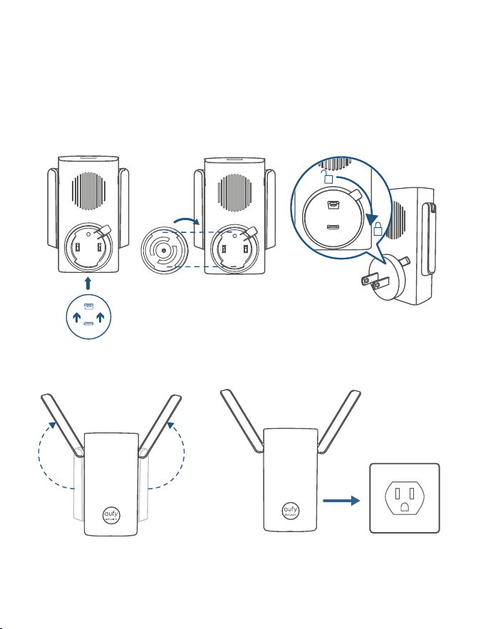
POWERING DOORBELL
CHIME
❷❶❸
❹❺
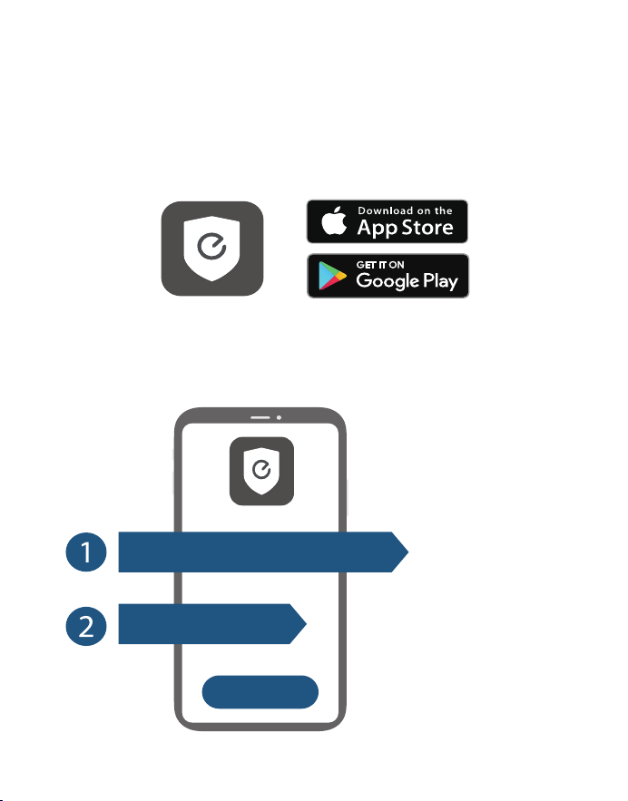
SETTING UP THE SYSTEM
1. Download and install the eufy Security app, then sign up for an account.
2. Follow on-screen instructions to add the doorbell chime first, and then the
smark lock to your device list.
1 doorbell chime can link up to 4
devices.
Make sure your Video Smart Lock
battery is charged, or it may fail
to be added to the eufy Security
app.
+
Wi-Fi Bridge&Doorbell Chime
Video Smart Lock

21 EN
EN 22
POWERING DOORBELL
CHIME
❷❶❸
❹❺
SETTING UP THE SYSTEM
1. Download and install the eufy Security app, then sign up for an account.
2. Follow on-screen instructions to add the doorbell chime first, and then the
smark lock to your device list.
1 doorbell chime can link up to 4
devices.
Make sure your Video Smart Lock
battery is charged, or it may fail
to be added to the eufy Security
app.
+
Wi-Fi Bridge&Doorbell Chime
Video Smart Lock

23 EN
EN 24
Class II equipment
Warning
– replacement of a battery with an incorrect type that can defeat a safeguard;
– disposal of a battery into fire or a hot oven, or mechanically crushing or cutting
of a battery, that can result in an explosion;
– leaving a battery in an extremely high temperature surrounding environment
that can result in an explosion or the leakage of flammable liquid or gas; and
– a battery subjected to extremely low air pressure that may result in an explosion
or the leakage of flammable liquid or gas.
CAUTION RISK OF EXPLOSION IF BATTERY IS REPLACED BY AN INCORRECT
TYPE. DISPOSE OF USED BATTERIES ACCORDING TO THE INSTRUCTIONS
IP protection class of model T8530: IP65 for exterior assembly, IPX0 for interior
assembly.
Notice (United States Of America)
FCC Statement
This device complies with Part 15 of the FCC Rules. Operation is subject to the
following two conditions: (1) this device may not cause harmful interference, and
(2) this device must accept any interference received, including interference that
may cause undesired operation.
Warning: Changes or modifications not expressly approved by the party
responsible for compliance could void the user's authority to operate the
equipment.
Note: This equipment has been tested and found to comply with the limits for
a Class B digital device, pursuant to Part 15 of the FCC Rules. These limits are
designed to provide reasonable protection against harmful interference in a
residential installation.
This equipment generates uses and can radiate radio frequency energy and, if
not installed and used in accordance with the instructions, may cause harmful
interference to radio communications. However, there is no guarantee that
interference will not occur in a particular installation. If this equipment does cause
harmful interference to radio or television reception, which can be determined
by turning the equipment off and on, the user is encouraged to try to correct the
interference by one or more of the following measures: (1) Reorient or relocate
the receiving antenna. (2) Increase the separation between the equipment and
NOTICE
6
receiver. (3) Connect the equipment into an outlet on a circuit different from that
to which the receiver is connected. (4) Consult the dealer or an experienced radio/
TV technician for help.
FCC Radio Frequency Exposure Statement
The device has been evaluated to meet general RF exposure requirements. The
device can be used in fixed/mobile exposure condition. The min separation
distance is 20cm.
Notice: Shielded cables
All connections to other computing devices must be made using shielded cables
to maintain compliance with FCC regulations.
The following importer is the responsible party
Company Name: POWER MOBILE LIFE, LLC
Address: 10900 NE 8th St, Ste 501, Bellevue WA 98004
Telephone:1-800-988-7973
Notice (Australia)
Do not use the Device in the environment at too high or too low temperature,
never expose the Device under strong sunshine or too wet environment.
It is recommended to supply the device in an environment with a temperature
that ranges from 5
°C
~25
°C
.
When supplying, please place the device in an environment that has a normal
room temperature and good ventilation.
Warning:
– replacement of a battery with an incorrect type that can defeat a safeguard;
– disposal of a battery into fire or a hot oven, or mechanically crushing or cutting
of a battery, that can result in an explosion;
– leaving a battery in an extremely high temperature surrounding environment
that can result in an explosion or the leakage of flammable liquid or gas; and
– a battery subjected to extremely low air pressure that may result in an explosion
or the leakage of flammable liquid or gas.
CAUTION RISK OF EXPLOSION IF BATTERY IS REPLACED BY AN INCORRECT
TYPE.DISPOSE OF USED BATTERIES ACCORDING TO THE INSTRUCTIONS
Your product is designed and manufactured with high quality materials and
components, which can be recycled and reused.
This symbol means the product must not be discarded as household
waste, and should be delivered to an appropriate collection facility for
recycling. Proper disposal and recycling helps protect natural resources,
human health and the environment. For more information on disposal and
recycling of this product, contact your local municipality, disposal service, or
the shop where you bought this product.

26 ES
ES 27
DESCRIPCIÓN GENERAL
❷
❶
❸
❻
❼
❹
❺
❽
❻
❾
❿
Escáner de huellas dactilares: Úselo para cerrar y abrir la
puerta.
Indicador de batería: Se vuelve rojo cuando el nivel de batería
es bajo.
Objetivo de la cámara
Micrófono
Sensor de luz ambiental: Detecta la cantidad de luz.
LED de infrarrojos
Teclado
Luz de estado y botón de cierre y apertura: Manténgalo
pulsado para activar el cierre de la puerta.
Azul: Puerta abierta.
Naranja: Puerta cerrada.
Rojo: Estado anómalo detectado.
Cilindro de la cerradura
Botón del timbre: La luz del anillo se enciende automáticamente
cuando alguien se acerca a la puerta.
Sensor de movimiento
Altavoz
Puerto USB-C: Permite cargar la cerradura en situaciones de
emergencia.
Botón de reinicio: Reinicia la cerradura.
eufy Security Video Smart Lock
Modelo: T8530
28 ES
ES 29
Cómo abrir y cerrar la tapa del cilindro de la
❶
❷
❻
❺
❹
❸
Batería
Número de serie
CódigoQR
Botón desincronización: Manténgalo pulsado para emparejarlo con el
timbre de la puerta.
Pestillo giratorio
Orificio para el tornillo
cerradura

28 ES
ES 29
Cómo abrir y cerrar la tapa del cilindro de la
❶
❷
❻
❺
❹
❸
Batería
Número de serie
CódigoQR
Botón desincronización: Manténgalo pulsado para emparejarlo con el
timbre de la puerta.
Pestillo giratorio
Orificio para el tornillo
cerradura
30 ES
ES 31
Ranura para tarjeta MicroSD: Para guardar las grabaciones de vídeo, inserte
una
tarjeta de memoria (se vende por separado)
Orificio de reinicio
Botón de sincronización
Puente de acceso wifi y timbre de puerta*
❸
❷
❶
Modelo: T8021
*
También se vende como puente de acceso wifi
PUERTAS COMPATIBLES
1" / 25 mm
2⅜" / 60 mm
2⅜" / 60 mm or
2¾" / 70 mm
2 ⅛" / 54 mm
1 ½" / 38 mm
1⅜" - 2 ⅛"
35 mm-55 mm
Profundidad
de la
cerradura
Distancia
mínima
Diámetro
de orificio
de la puerta
Diámetro
del orificio
transversal
Grosor de
la puerta
32 ES
ES 33
INSTALACIÓN DEL VIDEO
SMART LOCK
»
PASO 1. Kit de montaje de cerrojo
»
PASO 2. Kit de montaje de placa protectora
Qué necesita
A
B
C D
E F
»
PASO 3. Panel exterior
»
PASO 4. Kit de montaje de pieza interior
G
H
I J K
L M
32 ES
ES 33
INSTALACIÓN DEL VIDEO
SMART LOCK
»
PASO 1. Kit de montaje de cerrojo
»
PASO 2. Kit de montaje de placa protectora
Qué necesita
A
B
C D
E F
»
PASO 3. Panel exterior
»
PASO 4. Kit de montaje de pieza interior
G
H
I J K
L M

34 ES
ES 35
PASO 1. Montaje del cerrojo
2-3/8
2-3/4
180°
2⅜" / 60 mm
2¾" / 70 mm
❷
❶
❸
❹
Si la profundidad de
la cerradura es de
70 mm, gire la placa
frontal 180° para
agrandarla.
Si el hueco para el bombín es
redondo, pida al servicio de
atención al cliente una placa
frontal redonda que encaje y
cámbiela la anterior.
1.Revise la puerta para comprobar si
debe ajustarse el cerrojo.
Profundidad
de la
cerradura
Espacio para
el bombín
2.Coloque y atornille el cerrojo en
el marco de la puerta.
A
B
Asegúrese de que la palabra
“TOP“ del cerrojo mire hacia
arriba.
36 ES
ES 37
PASO 2. Instalación de la placa protectora
C D
C D
E F
Opción 1
Opción 2 Ponga la placa de refuerzo para que la
sujeción sea mayor.
PASO 3. Instalación de la pieza exterior
Si el orificio transversal
es de 38 mm, retire el
separador antes de
montarla.
Cross bore
diameter
1 ½" or 38 mm

36 ES
ES 37
PASO 2. Instalación de la placa protectora
C D
C D
E F
Opción 1
Opción 2 Ponga la placa de refuerzo para que la
sujeción sea mayor.
PASO 3. Instalación de la pieza exterior
Si el orificio transversal
es de 38 mm, retire el
separador antes de
montarla.
Cross bore
diameter
1 ½" or 38 mm
38 ES
ES 39
PASO 4. Instalación de la pieza interior
1.Quite la tapa trasera
de la pieza interior.
2.Pase los cables por la tapa trasera.
H
I
Apriete bien los tornillos.
Enrosque los tornillos con
las manos y luego use
un destornillador para
fijarlos bien.
3.Atornille la tapa trasera.
I

38 ES
ES 39
PASO 4. Instalación de la pieza interior
1.Quite la tapa trasera
de la pieza interior.
2.Pase los cables por la tapa trasera.
H
I
Apriete bien los tornillos.
Enrosque los tornillos con
las manos y luego use
un destornillador para
fijarlos bien.
3.Atornille la tapa trasera.
I

40 ES
ES 41
4. (Opcional) Si la tapa trasera no está bien sujeta a la puerta, use el tornillo
adicional incluido.
J
5. Conecte el cable a la pieza interior.
Posición al revés
40 ES
ES 41
4. (Opcional) Si la tapa trasera no está bien sujeta a la puerta, use el tornillo
adicional incluido.
J
5. Conecte el cable a la pieza interior.
Posición al revés
42 ES
ES 43
6. Mount the interior assembly. Make sure both wires are tucked into the
cabin on the back of the interior assembly.
Compruebe que el cerrojo se
mueve al girar el pasador
K
42 ES
ES 43
6. Mount the interior assembly. Make sure both wires are tucked into the
cabin on the back of the interior assembly.
Compruebe que el cerrojo se
mueve al girar el pasador
K

44 ES
ES 45
L
7. Cargue la batería del todo antes del primer uso. Puede tardar unas 6 horas.
M
Indicador LED
Rojo: Cargando
Azul: Carga
completa
44 ES
ES 45
L
7. Cargue la batería del todo antes del primer uso. Puede tardar unas 6 horas.
M
Indicador LED
Rojo: Cargando
Azul: Carga
completa
46 ES
ES 47
CÓMO ENCENDER EL
TIMBRE DE LA PUERTA
❷❶❸
❹❺
CONFIGURACIÓN DEL
SISTEMA
1.Descargue e instale la aplicación eufy Security y regístrese para disponer de una
cuenta.
2.Siga las instrucciones en pantalla para añadir primero el sonido del timbre y
luego la cerradura inteligente a la lista de dispositivos.
Un timbre de puerta puede tener
vinculados hasta 4 dispositivos.
Compruebe que la batería del
Video Smart Lock está cargada;
de lo contrario, es posible que
no se añada a la aplicación eufy
Security.
+
Wi-Fi Bridge&Doorbell Chime
Video Smart Lock
48 ES
Equipo de clase II
Advertencia
– si cambia una batería por otra incorrecta, se podría anular la protección;
– si tira la batería al fuego o la pone en un horno caliente, o si la aplasta o corta
por medios mecánicos, podría provocar una explosión;
– si deja una pila en una zona con una temperatura muy alta podría dar lugar a
una explosión o la fuga de líquido o gas inflamable; y
– una batería sometida a una presión de aire extremadamente baja puede
provocar una explosión o la fuga de líquidos o gases inflamables.
PRECAUCIÓN: PUEDE EXISTIR RIESGO DE EXPLOSIÓN SI LA BATERÍA SE
SUSTITUYE POR OTRA DE UN TIPO INCORRECTO.TIRE LAS PILAS USADAS
TAL Y COMO SE INDICA EN LAS INSTRUCCIONES
Grado de protección IP del modelo T8530: IP65 en la pieza exterior y IPX0 en la
pieza interior.
AVISO
6

49 FR
FR 50
Lecteur d'empreintes digitales: utilisez-le pour verrouiller et
déverrouiller la porte.
Témoin de batterie: devient rouge lorsque la batterie est faible.
Objectif de la caméra
Microphone
Détecteur de lumière ambiante: détecte la quantité de
lumière.
DEL IR
Clavier
Voyant d'état et bouton de verrouillage et de déverrouillage:
appuyez et maintenez enfoncé pour verrouiller la porte.
Bleu: porte déverrouillée.
Orange: porte verrouillée.
Rouge: état anormal détecté.
Barillet de serrure
Bouton de sonnette: l'anneau lumineux s'allume
automatiquement lorsque quelqu'un s'approche de la porte.
Détecteur de mouvement
Haut-parleur
Port USB-C: permet de charger la serrure dans les situations
d'urgence.
Bouton de redémarrage: redémarre la serrure.
APERÇU
❷
❶
❸
❻
❼
❹
❺
❽
❻
❾
❿
eufy Security Video Smart Lock
Modèle: T8530
51 FR
FR 52
Comment ouvrir/fermer le couvercle du
barillet de serrure
❶
❷
❻
❺
❹
❸
Batterie
Numéro de série
Code QR
Bouton SYNC: maintenez enfoncé pour coupler avec le carillon de la
sonnette.
Barrette tournante
Trou de vis
51 FR
FR 52
Comment ouvrir/fermer le couvercle du
barillet de serrure
❶
❷
❻
❺
❹
❸
Batterie
Numéro de série
Code QR
Bouton SYNC: maintenez enfoncé pour coupler avec le carillon de la
sonnette.
Barrette tournante
Trou de vis
53 FR
FR 54
Logement pour carte MicroSD: pour stocker des enregistrements vidéo,
insérez une
carte mémoire (vendue séparément)
Orifice de réinitialisation
Bouton SYNC
Pont Wi-Fi et carillon de sonnette*
❸
❷
❶
Modèle: T8021
PORTES COMPATIBLES
1" / 25 mm
2⅜" / 60 mm
2⅜" / 60 mm or
2¾" / 70 mm
2 ⅛" / 54 mm
1 ½" / 38 mm
1⅜" - 2 ⅛"
35 mm-55 mm
*
Également vendu comme pont Wi-Fi
Support
Distance
minimale
Diamètre
de baie de
porte
Diamètre
d'alésage
transversal
Épaisseur
de la porte
55 FR
FR 56
INSTALLATION DE
LA SERRURE VIDÉO
INTELLIGENTE
»
ÉTAPE1. Kit d'installation de pêne dormant
»
ÉTAPE2. Kit d'installation de gâche
»
ÉTAPE3. Montage extérieur
»
ÉTAPE4. Kit d'installation d'ensemble intérieur
Éléments requis
A
B
C D
E F
G
H
I J K
L M

55 FR
FR 56
INSTALLATION DE
LA SERRURE VIDÉO
INTELLIGENTE
»
ÉTAPE1. Kit d'installation de pêne dormant
»
ÉTAPE2. Kit d'installation de gâche
»
ÉTAPE3. Montage extérieur
»
ÉTAPE4. Kit d'installation d'ensemble intérieur
Éléments requis
A
B
C D
E F
G
H
I J K
L M

57 FR
FR 58
ÉTAPE1. Installer le pêne dormant
2-3/8
2-3/4
180°
2⅜" / 60 mm
2¾" / 70 mm
❷
❶
❸
❹
Si le support est
de 70 mm, tournez
la façade de 180°
pour augmenter la
longueur.
Si le trou de la serrure est
rond, contactez le service
client pour recevoir une
plaque frontale ronde et
remplacer la plaque existante.
1.Vérifiez votre porte pour voir si
le pêne dormant nécessite un
ajustement.
2.Insérez et vissez le pêne dormant
dans le cadre de la porte.
A
B
Assurez-vous que le mot
«TOP» sur le pêne dormant
est orienté vers le haut.
Support
Trou de la
serrure
59 FR
FR 60
ÉTAPE2. Installer la gâche
C D
C D
E F
Option 1
Option2: ajoutez le renfort de butée pour plus de
sécurité.
ÉTAPE3. Installer l'ensemble extérieur
Si vous avez un alésage
transversal de 38 mm,
retirez l'entretoise avant
l'installation.
Cross bore
diameter
1 ½" or 38 mm

59 FR
FR 60
ÉTAPE2. Installer la gâche
C D
C D
E F
Option 1
Option2: ajoutez le renfort de butée pour plus de
sécurité.
ÉTAPE3. Installer l'ensemble extérieur
Si vous avez un alésage
transversal de 38 mm,
retirez l'entretoise avant
l'installation.
Cross bore
diameter
1 ½" or 38 mm

61 FR
FR 62
H
I
ÉTAPE4. Installer l'ensemble intérieur
1.Détachez le capot
arrière de l'ensemble
intérieur.
Serrez fermement les vis
en place. Serrez les vis à
la main, puis utilisez un
tournevis pour les fixer.
3.Fixez le capot arrière avec des vis.
I
2.Faites passer les fils à travers le capot
arrière.

63 FR
FR 64
4. (Facultatif) Si le capot arrière n'est pas solidement fixé à la porte, utilisez la vis
supplémentaire fournie.
J
5.
Câblez à l'ensemble intérieur.
La tête en bas

63 FR
FR 64
4. (Facultatif) Si le capot arrière n'est pas solidement fixé à la porte, utilisez la vis
supplémentaire fournie.
J
5.
Câblez à l'ensemble intérieur.
La tête en bas

65 FR
FR 66
6. Mount the interior assembly. Make sure both wires are tucked into the
cabin on the back of the interior assembly.
Vérifiez si le pêne dormant
se rétracte en tournant le
bouton
K

65 FR
FR 66
6. Mount the interior assembly. Make sure both wires are tucked into the
cabin on the back of the interior assembly.
Vérifiez si le pêne dormant
se rétracte en tournant le
bouton
K
67 FR
FR 68
7. Chargez complètement la batterie avant la première utilisation. Cela peut
prendre environ 6heures.
L
M
Voyant LED
Rouge: en
charge
Bleu: charge
terminée
67 FR
FR 68
7. Chargez complètement la batterie avant la première utilisation. Cela peut
prendre environ 6heures.
L
M
Voyant LED
Rouge: en
charge
Bleu: charge
terminée

69 FR
FR 70
ALIMENTATION DU
CARILLON DE SONNETTE
❷❶❸
❹❺
CONFIGURATION DU
SYSTÈME
1.Téléchargez et installez l’application eufy Security, puis inscrivez-vous pour
obtenir un compte.
2.Suivez les instructions à l'écran pour ajouter d'abord le carillon de la sonnette,
puis la serrure intelligente à votre liste d'appareils.
1 carillon de sonnette peut être
relié à 4 appareils maximum.
Assurez-vous que la batterie de
votre serrure vidéo intelligente
est chargée, sinon elle risque de
ne pas être ajoutée à l'application
eufy Security.
+
Wi-Fi Bridge&Doorbell Chime
Video Smart Lock

71 FR
FR 72
Équipement de classe II
Avertissement
– le remplacement d’une batterie par un type incorrect est susceptible de
neutraliser une protection;
- la mise au rebut d’une batterie dans un feu ou un four chaud, ou l’écrasement
ou le découpage mécanique d’une batterie, peut entraîner une explosion;
- le stockage d’une batterie dans un environnement où la température est
extrêmement élevée peut entraîner une explosion ou la fuite d’un liquide ou d’un
gaz inflammable; et
- une batterie soumise à une pression d'air extrêmement basse peut entraîner
une explosion ou une fuite de liquide ou de gaz inflammable.
ATTENTION: IL EXISTE UN RISQUE D'EXPLOSION SI LA BATTERIE EST
REMPLACÉE PAR UN MODÈLE INAPPROPRIÉ.
JETEZ LES BATTERIES USAGÉES CONFORMÉMENT AUX INSTRUCTIONS
Classe de protection IP du modèle T8530: IP65 pour l'ensemble extérieur, IPX0
pour l'ensemble intérieur.
AVIS
6
Notice (Canada)
This device complies with Industry Canada licence-exempt RSS standard(s).
Operation is subject to the following two conditions: (1)this device may not cause
interference, and (2)this device must accept any interference, including interference
that may cause undesired operation of the device.
Le présent appareil est conforme aux CNR d'Industrie Canada applicables aux
appareils radio exempts de licence. L'exploitation est autorisée aux deux
conditions suivantes: (1)l'appareil nedoit pas produire de brouillage, et (2)l'utilisateur
de l'appareil doit accepter tout brouillage radioélectrique subi, même si le brouillage
est susceptible d'en compromettre le fonctionnement.
This Class B digital apparatus complies with Canadian ICES-003.
Cet appareil numérique de la classe B est conforme à la norme NMB-003 du Canada.
IC RF Statement:
When using the product, maintain a distance of 20cm from the body to ensure
compliance with RF exposure requirements.
Lors de l'utilisation du produit, maintenez une distance de 20 cm du corps afin de
vous conformer aux exigences en matière d'exposition RF.
Attention:
– remplacement d’une batterie par un type incorrect pouvant supprimer une
protection
– mise au rebut d’une batterie dans un feu ou dans un four chaud, ou écrasement
mécanique ou coupure d’une batterie, susceptible de provoquer une explosion;
– maintien d’une batterie dans un environnement à très haute température
pouvant provoquer une explosion ou la fuite de liquide ou de gaz inflammables;
et
– batterie soumise à une pression de l’air extrêmement faible pouvant provoquer
une explosion ou la fuite de liquide ou de gaz inflammables.
ATTENTION RISQUE D'EXPLOSION SI LA BATTERIE EST REMPLACÉE PAR UN
TYPE INCORRECT. ÉLIMINER LES BATTERIES USÉES SELON LES INSTRUCTIONS
12-month limited warranty
United States
+1 (800) 988 7973
Mon-Sat 6:15AM-6:45PM(PT)
Sun 6:15AM-5:45PM(PT)
United Kingdom
+44 (0) 1604 936 200
Mon-Sun 6:00-19:00
Germany
+49 (0) 69 9579 7960
Mo-Fr 8:00-16:00 Sa 9:00-16:00
@EufyOfficial @EufyOfficial @EufyOfficial
Anker Innovations Limited
Room 1318-19, Hollywood Plaza, 610 Nathan Road, Mongkok, Kowloon, Hong Kong
