Loading ...
Loading ...
Loading ...
Owner’s Manual
17
*
*
*
*
A
B
A
B
D
X6
X2
12
25
F
X4
6mm
6mm
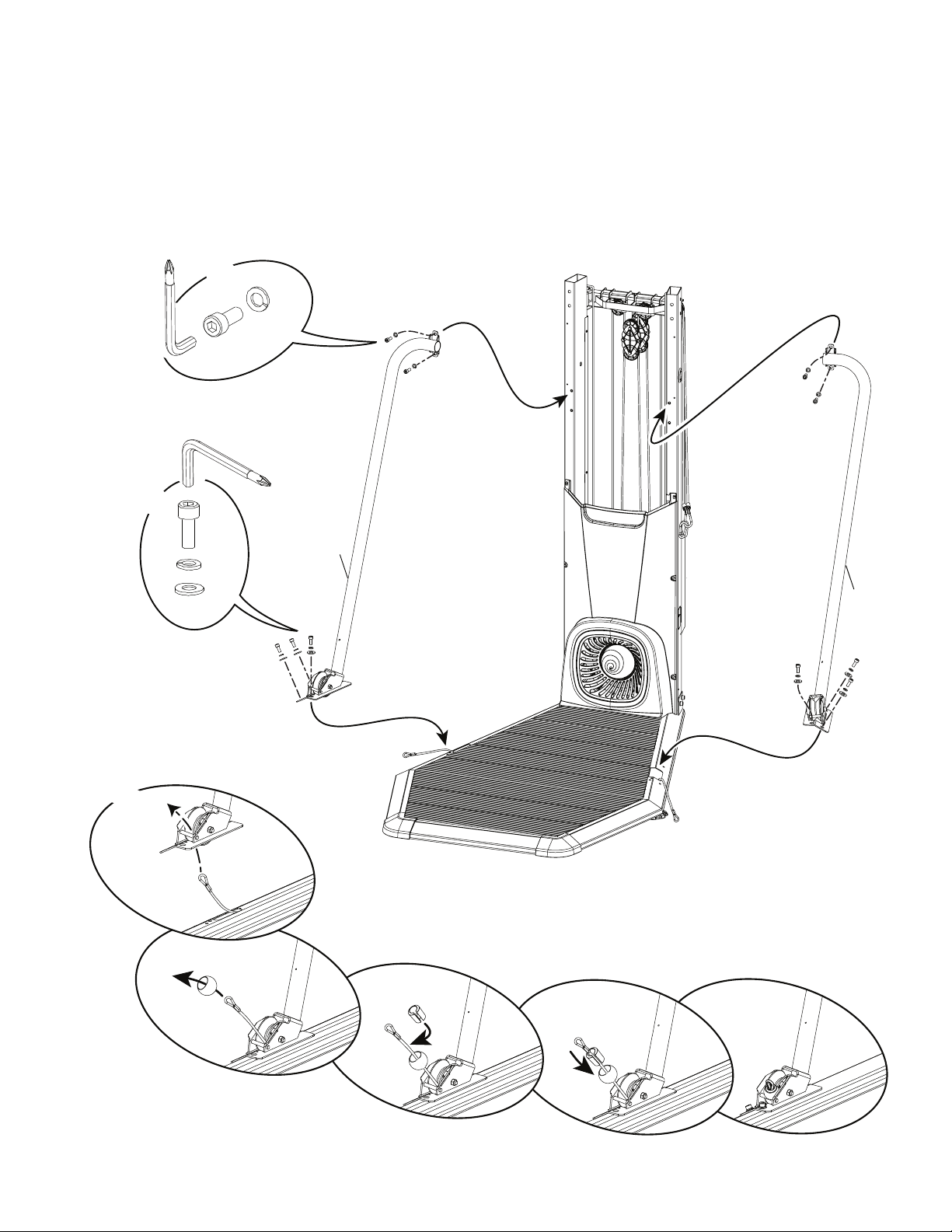
8. Route the Lower Rope and Attach the Support Arms and Securing Ball
Note: Route Lower Rope through the Support Arm. Then attach the upper hardware rst ( * ). Only nger-tighten the hardware until
instructed to fully tighten. Attach Securing Ball to Rope and remove the routing wire. Start the rope through the oval opening of the securing ball, and
pull out of the round opening.
Loading ...
Loading ...
Loading ...