
Loading ...
Loading ...
Loading ...
9
5. ASSEMBLY INSTRUCTIONS
A. Before assembling make sure that you will have enough space around the item.
B. Use the present tooling for assembling.
C. Before assembling please check whether all needed parts are available. Above of this instruction
sheet you will find an explosion drawing with all single parts (marked with numbers) which this item
consists of.
FIG. 1
FIG. 2
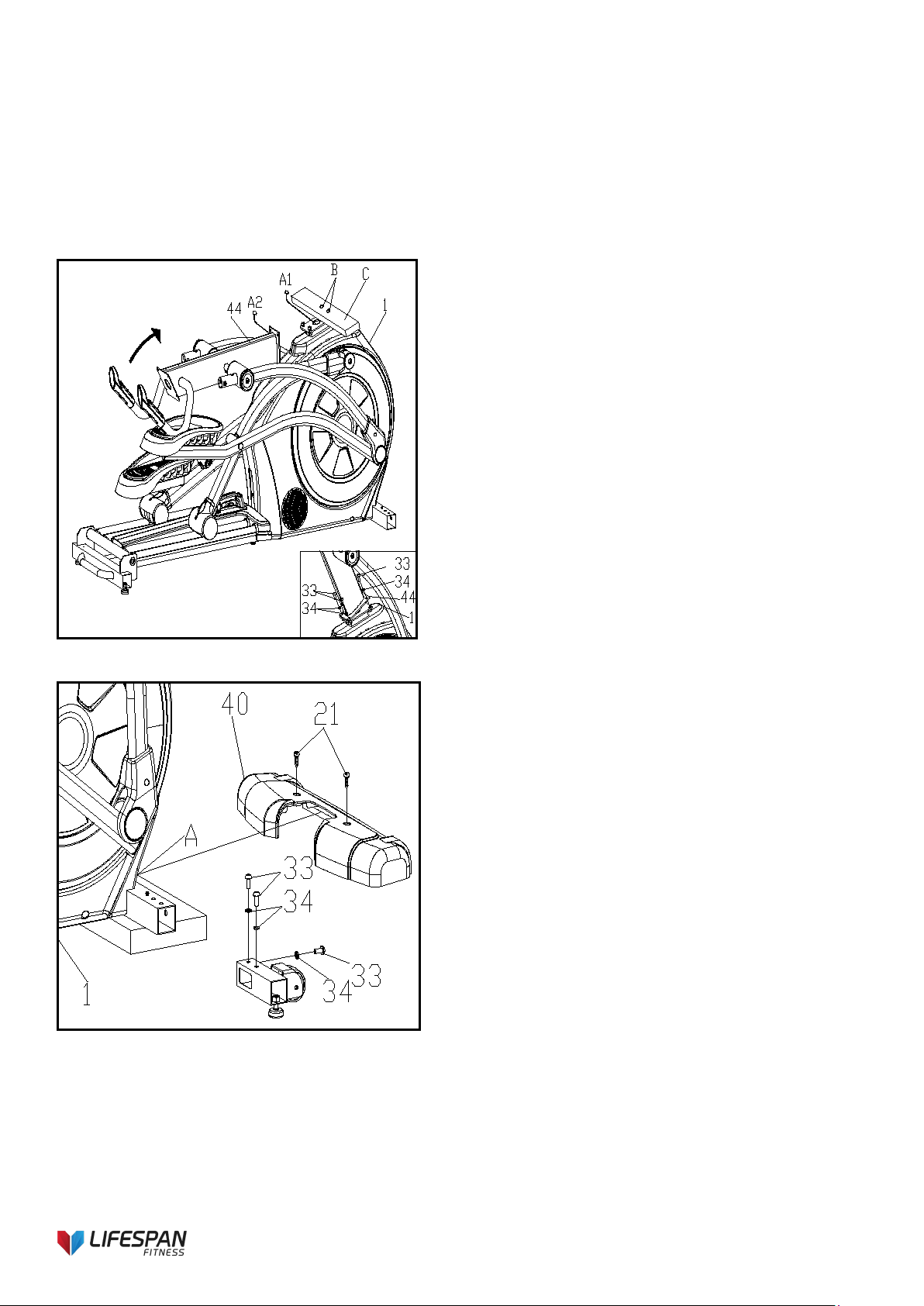
FIG.1:
1. Remove the pre-lock board (C) and two bolts (B)
at the front end of the main frame assembly (1)
and throw them away. Follow-up installation
steps are not needed.
2. As shown in the figure, turn the upper column
assembly (44) in the direction of arrow until the
upper column assembly (44) is close to the main
frame assembly (1). One person holds the upper
column assembly (44) and the other person
connects the signal line (A1-A2) after the
connection is completed. The terminal is inserted
into a large sheet metal hole on the main frame
assembly (1) to avoid overwhelming the signal
line.
3. As shown in the figure, the sheet metal on the
upper column assembly (44) is clamped into the
main frame assembly (44) which is pre-locked.
FIG.2:
1. As shown in the figure, the main frame assembly
(1) is padded with packing material (A), and the
screw (33), (34) which is pre-locked on the
connecting pipe assembly of the left and right
front foot tubes and the upper screw (21) of the
main frame assembly (1) are put on the side and
back for assembly.
2. The right front foot connecting pipe assembly (3)
is inserted into the square pipe corresponding to
the main frame assembly (1) and locked with
three M8*20 internal hexagonal screws (33) and
eight elastic gaskets (34). The other side is
assembled in the same way.
3. Take the packing material (A) padded under the
main frame assembly (1). Cover the front cover
(40) on the square pipe at the front end of the
main frame assembly (1). Lock it with two 4.2*19
cross groove disc head screws (21).
Loading ...
Loading ...
Loading ...