
Loading ...
Loading ...
Loading ...
11
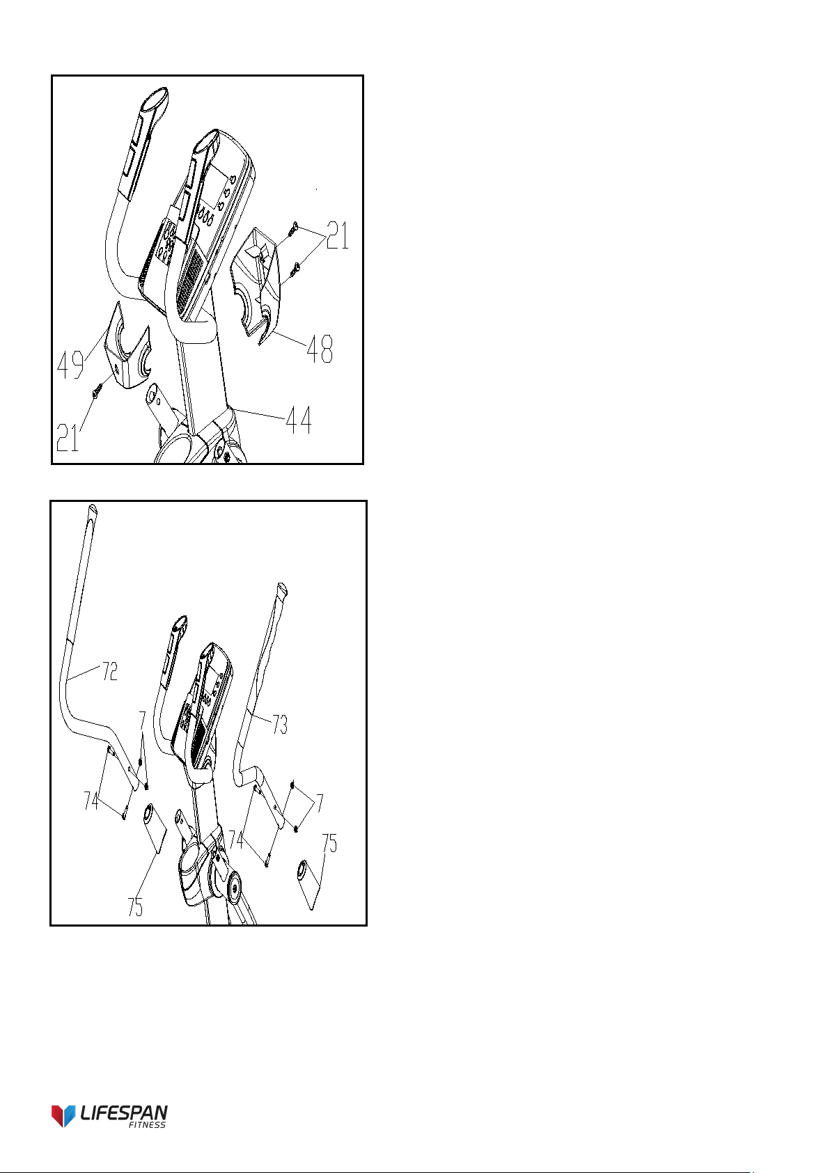
FIG. 6
FIG.7
FIG.6:
1. As shown in the figure, three screws (21) which
are pre-locked on the instrument tube assembly
(44) are removed first. Then, the instrument back
cover (49) and the instrument front cover (48)
are fixed on the instrument tube assembly (44)
with three self-tapping screws (21) with 4.2*19
cross groove disk head.
FIG.7:
1. As shown in the figure, remove four M8*45
hexagonal head screws and four M8 anti-
loosening nuts that are pre-locked on the left-
and right-hand rocker tube (72) (73).
2. Then two shaker caps (75) are inserted into the
left and right shaker caps (72) (73). Insert the left
handshake tube (72) into the left handshake tube
assembly circular tube and lock it with two M8*45
hexagonal head screws and two M8 anti-
loosening nuts (pay attention to the direction of
the head of the screw).
3. Finally, put down the shaker cover (75). The
assembly steps on the other side are the same.
Loading ...
Loading ...
Loading ...