
Loading ...
Loading ...
Loading ...
10
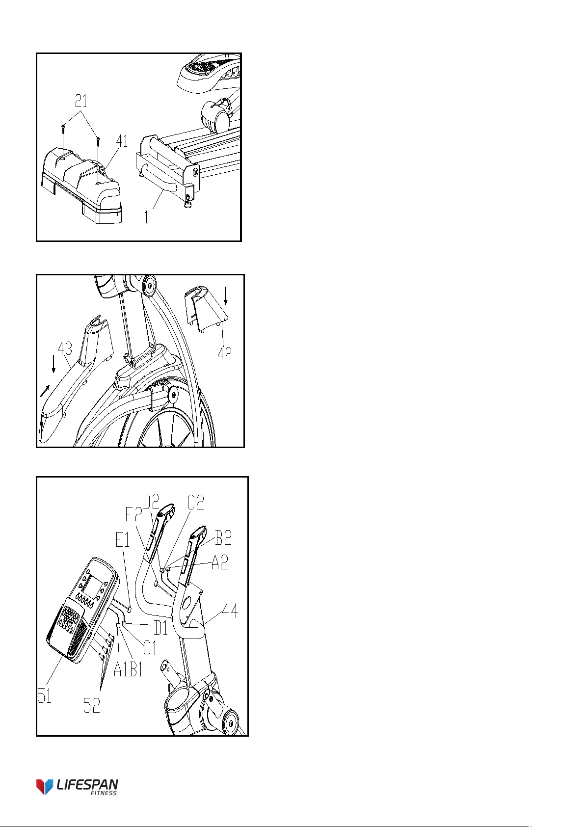
FIG. 3
FIG.3:
1. As shown in the figure, remove two 4.2*19 cross
groove head tapping screws (21) pre-locked on
the main frame assembly (1) and lock the rear
cover (41) on the main frame assembly (1).
FIG.4:
1. As shown in the figure, the chain cover rear
cover (43) and chain cover front cover (43) is
assembled on the main frame assembly (1).
FIG.4
FIG.5
FIG.5:
1. As shown in the figure, the wires under the
electronic meter (51) are connected together
according to (A1-A2) (B1-B2) (C1-C2) (D1-D2)
(E1-E2) l, and the terminals are inserted into the
large sheet metal hole on the instrument tube
assembly (44) to avoid overwhelming the signal
line.
2. Finally, the electronic meter (51) is fixed to the
instrument tube assembly (44) with four M5*8
cross groove head screws on the electronic
meter (51).
Loading ...
Loading ...
Loading ...