Loading ...
Loading ...
Loading ...
ENGLISH
6
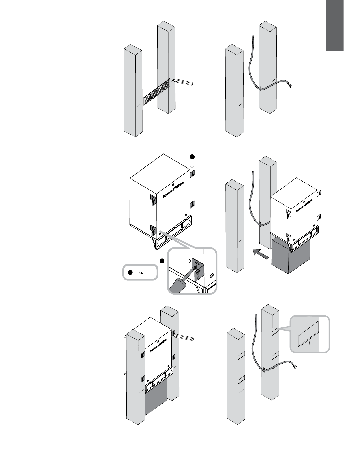
Figure 15
4 Installation in-wall
The subwoofer is too deep to t into a standard
nominal 100mm (4in) thick wall, but may be tted
into custom furniture or closet that accommodates
its depth and that has studs with standard 40cm
(16in) or greater spacing.
In most situations, the visible louvre will be required
to be low on the wall, just above the skirting board.
In that case, the cabinet will be oriented with the
cowl at the bottom.
On the front face of the studs each side of the
subwoofer, draw a horizontal line marking where the
centre line of the louvre fascia should be (Figure 15).
Run appropriate gauge speaker cable to the
installation point. Secure it to the studs so it cannot
rattle, with the nal tie point close to the marked
louvre centre line. Leave approximately 30cm –
50cm (12in - 20in) free at the end (Figure 16).
Screw the four L-brackets (g) to the sides of the
subwoofer cabinet as shown using two No.8 x
12mm (0.5in) screws (h) per bracket. (Figure 17)
The vertical position of the brackets is not critical,
but make sure they are ush with the front of the
cabinet.
It is not essential, but it is easier to t the subwoofer
if you support it temporarily underneath to bring the
louvre to the correct height.
Slide the subwoofer into the desired mounting
position (Figure 18).
Mark the outline of the brackets on the front of the
studs. (Figure 19)
Then remove the subwoofer and rebate the studs
between the mark lines as shown to a depth of
2mm (0.08 in) so that the brackets do not bulge the
drywall panel when tted (Figure 20).
Figure 16
Figure 17 Figure 18
x 8
h
g
h
Figure 19 Figure 20
2mm (0.08in)
Loading ...
Loading ...
Loading ...