Loading ...
Loading ...
Loading ...
ENGLISH
a
d
l
x 10
l
f
12
Figure 40
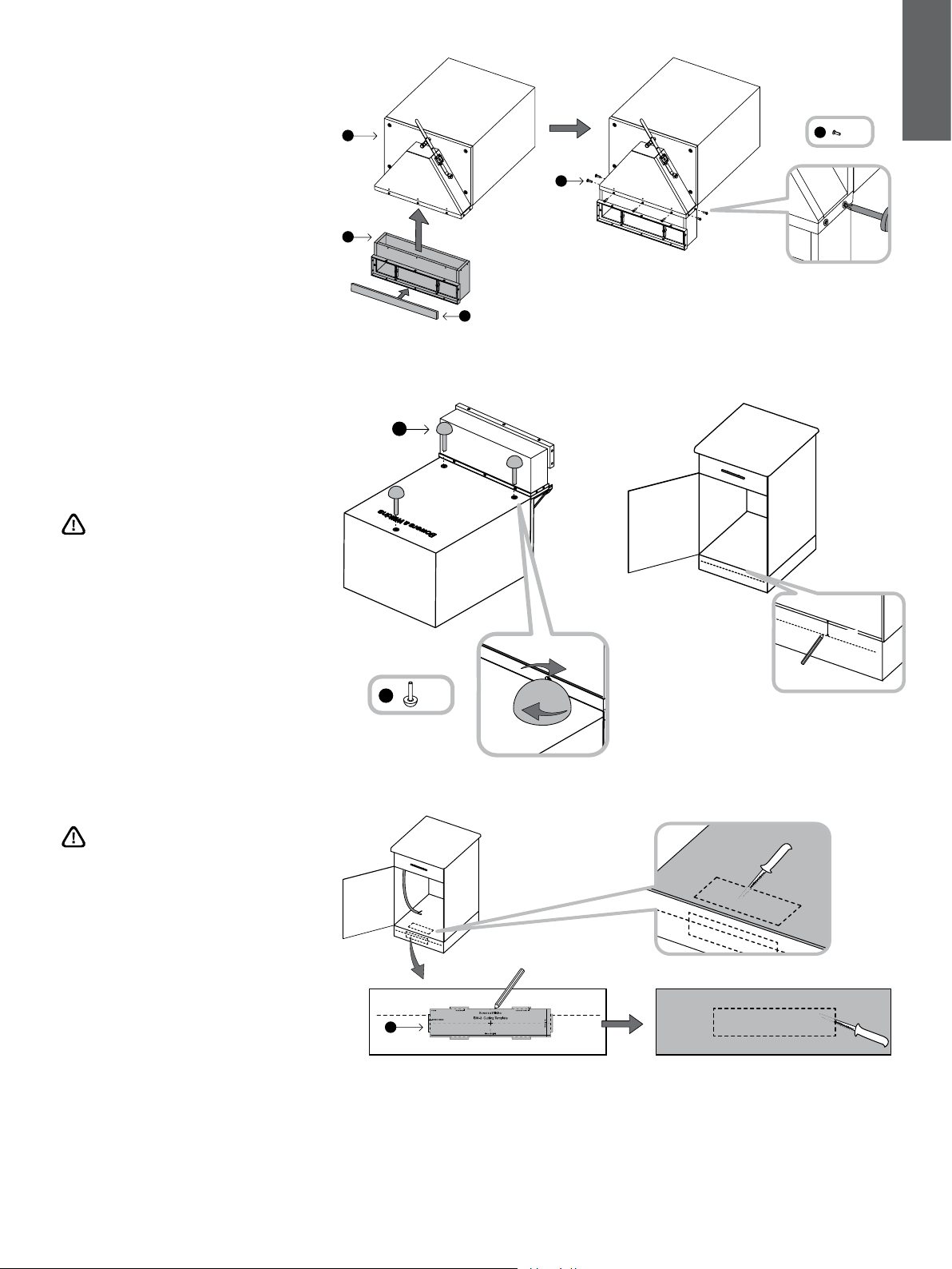
6 Installation in a kitchen unit
The subwoofer will rest on the bottom shelf of the
unit and vent through the toekick panel below the
door.
Remove the backing paper and x one of the gasket
strips (f) to the cowl extension, along the edge of its
louvre frame.
Attach the cowl extension (d) to the louvre frame on
the main cabinet, using the 10 No.4 x 10mm screws
(l) into the pre-drilled pilot holes (Figure 40).
There is a pre-tted gasket on the louvre frame
moulding attached to the cowl. This must be
compressed when tting the exrtension and the pilot
holes will not line up unless the gasket is properly
compressed.
Ensure the locknuts are fully screwed down on the
threaded stems of the rubber feet (k) and screw
all three feet fully into the threaded inserts in the
subwoofer cabinet (Figure 41).
Make a mark on the toekick panel 30mm
(1.2in) down from the surface of the bottom
shelf. The top of the cut-out in the panel
must not come below this line (Figure 42).
Using the supplied template, mark the cut-
out on the toekick panel as desired, making
sure the top of the template is at or above
the mark and that it is squarely aligned.
Cut the hole in the toekick panel and another in the
bottom shelf of the unit to clear the cowl extension.
The front of the hole in the shelf should be ush with
the back of the toe-kick panel (Figure 43).
Run appropriate gauge speaker cable to the
installation point.
Figure 43
h
Figure 41
k
x 3
k
30mm (1.2in)
Figure 42
e
Loading ...
Loading ...
Loading ...