Loading ...
Loading ...
Loading ...
ENGLISH
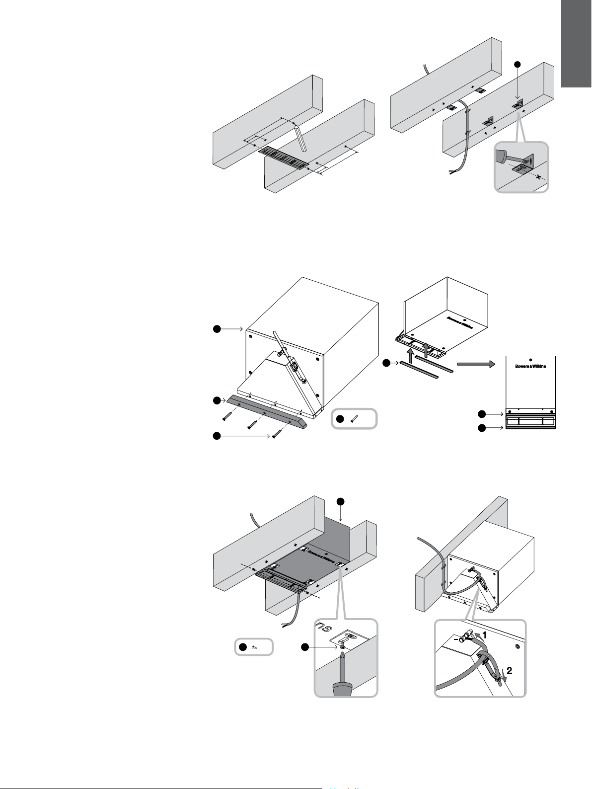
3 Installation in-ceiling
The speaker will t between joists with standard
40cm (16in) or greater spacing, such that the visible
louvre straddles the gap between them. A clearance
of 25cm (10in) or greater behind the underside face
of the joists is required.
Mark the centre line of the desired louvre position on
the underside face of the joists at each side. Make
two further marks on both joists at approximately
75mm (3in) and 380mm (15in) from the louvre centre
line for the cabinet support brackets (Figure 6).
Screw the four L-brackets (g) as shown to the inside
vertical faces of the joists (screws not supplied),
ensuring the brackets are square and ush with the
underside face of the joists.
Run appropriate gauge speaker cable to the
installation point. Secure it to the joists so it cannot
rattle, with the nal tie point close to the marked
louvre centre line near the top of the joist. Leave
approximately 30cm – 50cm (12in - 20in) free at the
end (Figure 7).
Attach the support bar (j) to the cowl using the
three No.6 x 25mm screws (m) and pre-drilled holes
(Figure 8).
Remove the backing paper and apply the two
self-adhesive gasket strips (f), one to the support bar
and one to the cabinet at the other side of the louvre
frame. These will bear on the drywall panel to avoid
rattles (Figure 9).
Lift the speaker to rest as shown on the four
L-brackets. If the joist spacing is too great to allow
screwing through the brackets into the cabinet, a
custom support method will need to be applied by
the installer.
Line the centre of the louvre aperture with the marks
on the joists and square it up relative to the walls.
Fix the cabinet position, using the No.8 x 12mm
self-tapping screws (h) through the L-brackets into
the cabinet (Figure 10).
The louvre frame will protrude below the bottom face
of the joists.
Strip the ends of the cable and connect to the spring
terminals on the cabinet, observing correct polarity.
To prevent rattles, secure the excess cable using the
cable tie attached to the subwoofer (Figure 11).
4
Figure 8
Figure 10 Figure 11
g
Figure 6 Figure 7
a
j
m
x 3
m
f
f
f
Figure 9
a
h
x 8
h
+
380mm (15in)
380mm (15in)
75mm (3in)
75mm (3in)
Loading ...
Loading ...
Loading ...