Loading ...
Loading ...
Loading ...
13
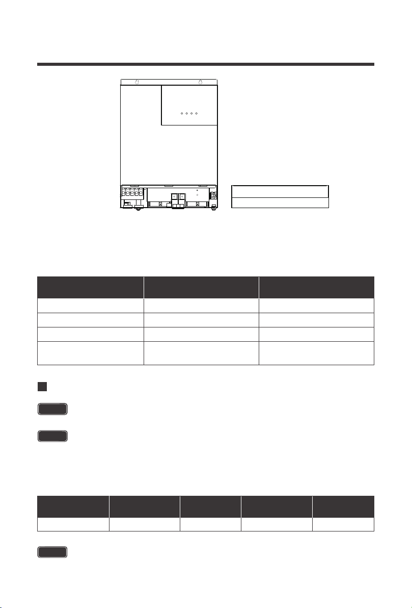
Wiring and installation methods must comply with national and local electrical specifications.
The following chart is reference only. Longer wire runs between solar panels and the solar
inverter as well as longer runs between the solar inverter and battery bank will require thicker
wiring size to minimize loss and improve system performance.
Be careful of the positive and negative poles. Reversing the poles may cause
permanent damage to the inverter.
The input terminals of the inverters have large capacitors connected to them. Once a
positive and negative wire are connected to the terminals, it will complete the circuit,
and commence drawing a heavy current momentarily. As a result, there may be a
sparking occurring even if the inverter is in the off position. To minimize sparking, it is
recommended that the user have the appropriate size wire feeding into the solar
inverters and/or install an external fuse leading into the inverter.
Specification Max Amps
Minimum Recommended
Wiring AWG
Battery Wiring
PV Wiring*
AC Input Wiring
AC Output Wiring
2AWG
4AWG
8AWG
8AWG
120A
80A
40A Max Bypass
30A Continuous
40A Max Bypass
Rated Battery
Discharge Current
Maximum Battery
Charging Current
Recommended
Wiring
Recommended
Circuit Breaker
Recommended
Ring Terminal
85A 120A 2AWG 2 pole, 140-160A 5/16”
Battery Wiring
NOTE
Make sure any circuit breakers are disconnected and ensure the unit is in the off
position.
NOTE
CAUTION
Loading ...
Loading ...
Loading ...