Version 1.1
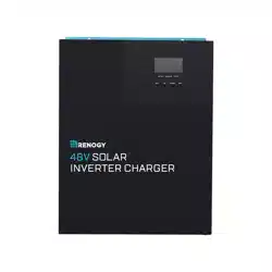
48V Pure Sine Wave Solar Inverter & Charger
SOLAR
INVERTER CHARGER
3500w
01
Important Safety Instructions
Please save these instructions.
This manual contains all safety, installation and operating instructions for the Solar Inverter
Charger. The following symbols are used throughout the manual:
DO NOT attempt to touch the unit while it is operating as temperatures will be very hot. In
addition, do not open the terminal cover while the unit is in operation.
Installation and wiring must comply with the Local and National Electric Codes (NEC) and
must be done by a certified technician.
Read all of the instructions and cautions in the manual before beginning the installation.
There are no serviceable parts for this inverter. Do NOT disassemble or attempt to repair
the inverter.
Make sure all connections going into and from the inverter are tight. There may be sparks
when making connections, therefore, make sure there are not flammable materials or
gases near installation.
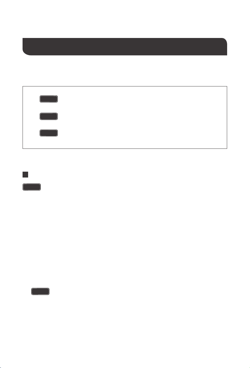
Indicates a potentially dangerous condition. Use extreme caution
when performing this task.
Indicates a critical procedure for safe and proper operation of the
inverter.
Indicates a procedure or function that is important to the safe and
proper operation of the inverter.
NOTE
CAUTION
WARNING
General Safety Information
Installing breakers or fuses outside of the unit is recommended.
After installation, check that all line connections are tight and secured.
DO NOT parallel this device with other AC input sources to avoid damage.

02
Do NOT let the positive (+) and negative (-) terminals of the battery touch each other.
Use Lithium batteries or deep cycle Sealed Lead Acid, Flooded, Gel, AGM batteries.
Explosive battery gases may be present while charging. Be certain there is enough
ventilation to release the gases.
Be careful when working with large lead acid batteries. Wear eye protection and have fresh
water available in case there is contact with the battery acid.
Over-charging and excessive gas precipitation may damage the battery plates and activate
material shedding on them. Too high of an equalizing charge or too long of one may cause
damage. Please carefully review the specific requirements of the battery used in the
system.
Battery Safety
The unit should be installed in a well-ventilated, cool, and dry environment. Make sure
the fans of the unit and the ventilation holes are not blocked.
Do not expose the unit to rain, moisture, snow, or liquids of any type.
Installation Safety

03
Table of Contents
Important Safety Instructions
General Information
Key Features
Battery Charging Modes
Load Output Working Modes
Product Overview
Dimensions
Optional Components
Installation
Location Recommendations
Wiring
Battery Wiring
PV Wiring
AC Output Wiring
AC Input Wiring
Communication Ports
Dry Contacts
RS485
CAN
USB
Operation
LCD Operation
LCD Menu
LCD Programmable Features
Electronic Protections
Fault Codes
Maintenance
Technical Specifications
Non-Lithium Battery Parameters
Lithium Battery Parameters
Charging Parameters Glossary
01
04
04
05
07
08
09
09
10
10
12
13
14
15
16
17
17
17
17
17
18
18
22
23
29
30
31
32
34
35
37

General Information
Key Features
04
The new all-in-one Renogy Solar Inverter Charger is an advanced hybrid system combining
the advanced charging algorithm of solar and industrial reliability and electrical energy of
pure sine wave inverters to give you a complete power system. The unit features 4 charging
modes and 3 output modes to meet an array of application needs. Utilizing the latest MPPT
tracking technology, the solar charging module can quickly track the maximum power point
of the photovoltaic array in any environment, capturing the maximum energy of solar panels
in real time. The AC-DC charging module adopts an advanced control algorithm resulting in
a powerful battery charger. The DC-AC inverter module is based on an all-digital intelligent
design, using advanced SPWM technology to output pure sine wave converting direct
current into alternating current, suitable for ac loads such as household appliances, power
tools, and industrial equipment.The product adopts a segment LCD display design, which
displays the operating data and operating status of the system. Lastly, the solar inverter
charger has comprehensive electronic protections to ensure that the entire system is more
secure and stable.
Complete electronic protection including: short-circuit protection, over-voltage protection,
overload protection and more!
Powerful bypass function with uninterrupted power supply function.
4 charging modes: PV Priority, Utility Priority, Hybrid Charging, Only Solar.
State-of-the-art MPPT technology with efficiency of up to 99.9%.
Dynamic LCD display and intelligent LEDs providing important system information.
Manual ON/OFF switch controlling AC output.
Power saving mode function, reduce empty load loss.
Adjustable fan, efficient heat dissipation, extending the life of the system.
Supports lead-acid battery and lithium battery types.
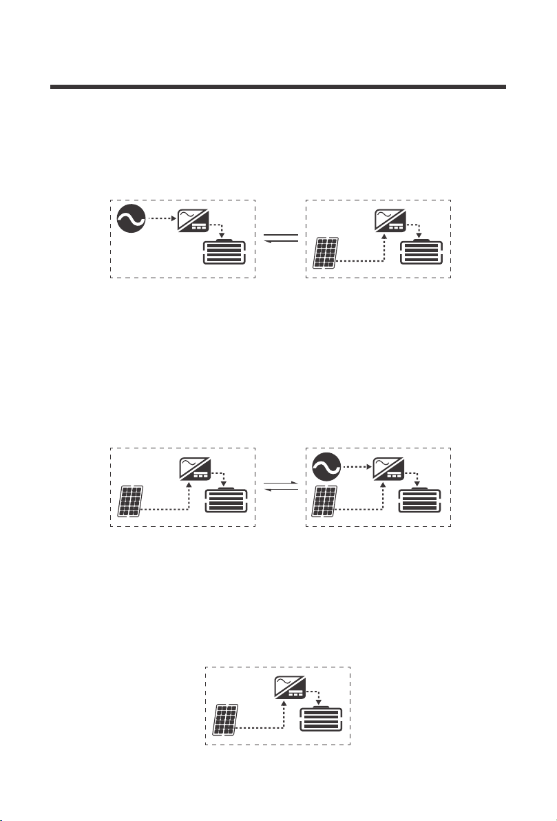
Battery Charging Modes:
05
The solar inverter will have 4 operational charging modes which changes the logic as how and
when to charge the battery banks. The solar inverter has four working modes: PV priority, Utility
Priority, Hybrid Charging, and Only Solar Charging.
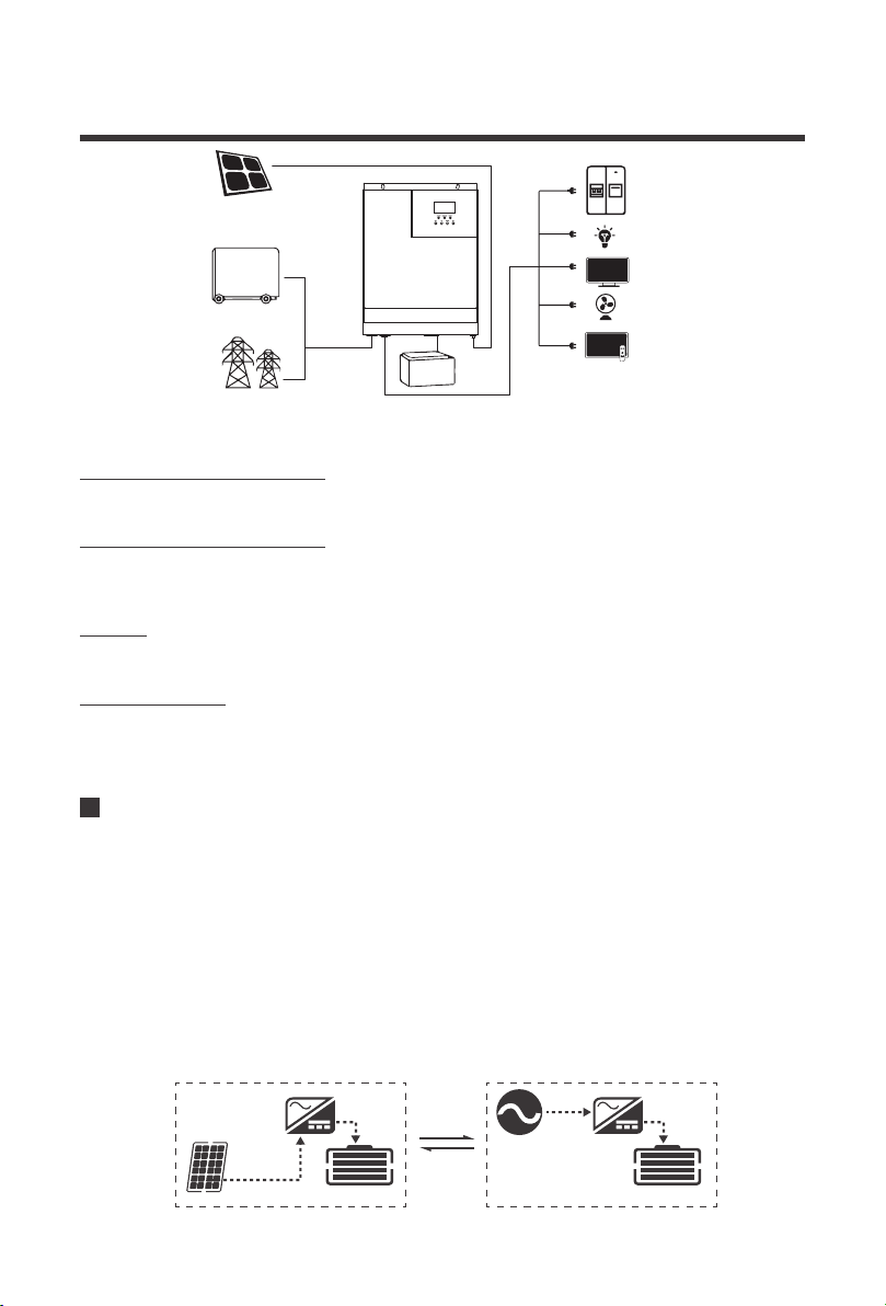
PV Priority
In PV Priority mode it will make full use of the solar input during the day in order to charge the
battery bank. This effectively allows using the unit off-grid during peak utility times in order to
cut costs on utility charging. Only when solar fails to start or is interrupted will the unit
automatically switch to utility mode for backup.
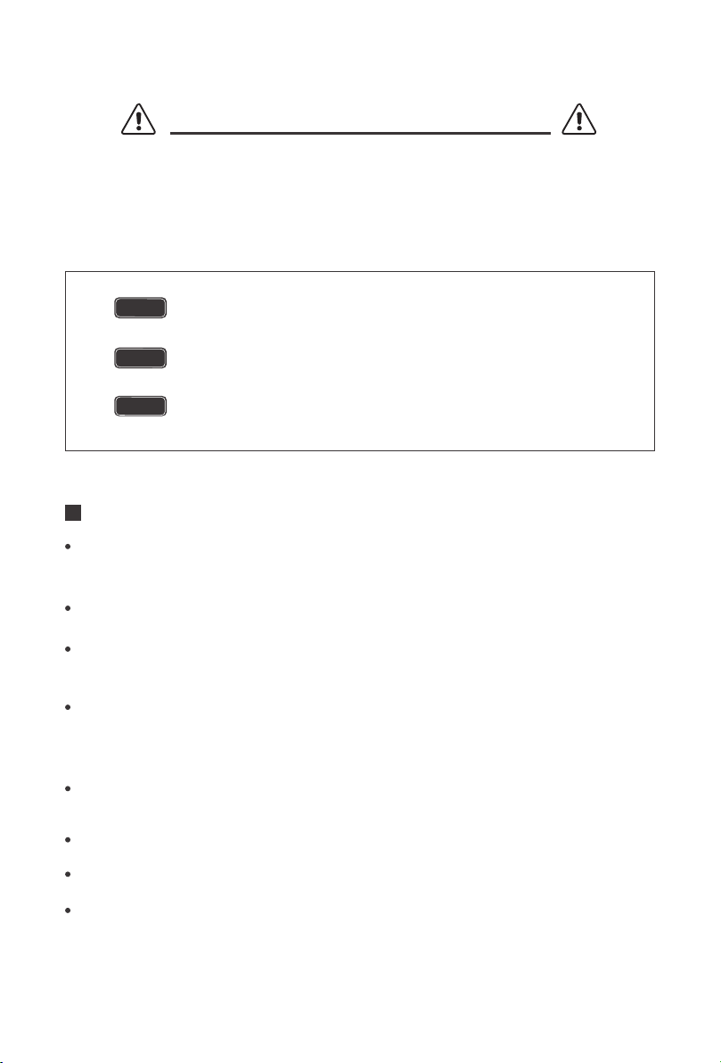
Photovoltaic Modules (PV): convert light energy into DC power, charge the battery through
the solar inverter charger, or directly reverse into alternating current to power the load.
PV
UTILITY
48V Battery Storage
Power or generator (Utility): Access at the AC input can power the load and charge the
battery. If you do not have a power supply or generator, the system can also operate normally,
where the load is supplied by batteries and photovoltaic modules.
Battery: The role of the battery is to ensure the normal use of electricity for the system load
when the solar energy is insufficient and there is no electricity.
Household load: Can be accessed to a variety of household and office loads, including
refrigerators, lamps, televisions, fans, air conditioning and other AC loads.
CHARGINGCHARGING
06
Utility Priority
In Utility Priority mode, the detected AC input will be priority for battery charging. If the power
becomes unstable or unusable, then it will switch to PV charging.
CHARGINGCHARGING
CHARGINGCHARGING
Hybrid Charging
In Hybrid Charging, PV and Utility will work together to charge the battery bank at the same
time. Priority will be given to PV and utilize MPPT charging. Upon PV charging being
insufficient, the power supply replenishes with Utility power. This method is the fastest to
charge and suitable for unstable areas of the grid, ready to provide adequate backup power
supply.
CHARGING
Only Solar Charging
Only solar charging is the most energy-efficient way to charge your battery bank and does not
make use of AC input. Utility will not charge the battery, even if it is available.
07
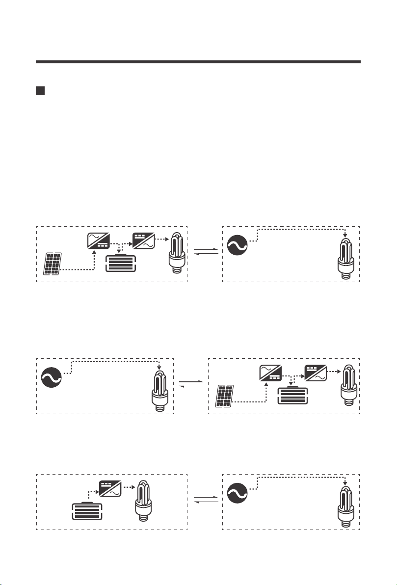
Load Output Working Modes
PV Priority
In this mode only the incoming solar energy and battery power are used to power the loads.
This can maximize the use of green energy when selecting PV priority in Battery Charging
Mode to achieve overall energy conservation and emission reduction. Upon there being no
more usable solar energy or the battery voltage drops to a low voltage setpoint, then the unit
will switch to utility power to continue to power up the loads. It is recommended to be in this
mode for relatively stable areas.
The solar inverter has 3 working modes that dictate how the incoming power is used to power
the loads.Users may configure the output source priority to configure load power.
CHARGING
CHARGING
CHARGING
Utility Priority
Equivalent to a backup UPS for use in unstable areas of the grid, Utility will provide power to
the loads as priority. Solar and battery energy will provide power to the loads only when utility
power is not available.
Inverter Mode
The Battery energy will supply power to the loads. Utility provides power to the loads only when
battery voltage drops to low voltage which maximizes the use of DC power.
08
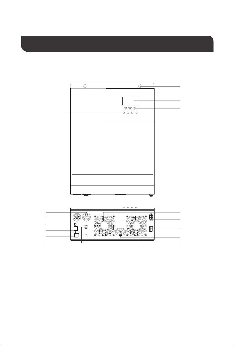
Product Overview
Key Parts
3
4
11
12
13
14
155
6
7
8
9
10
1
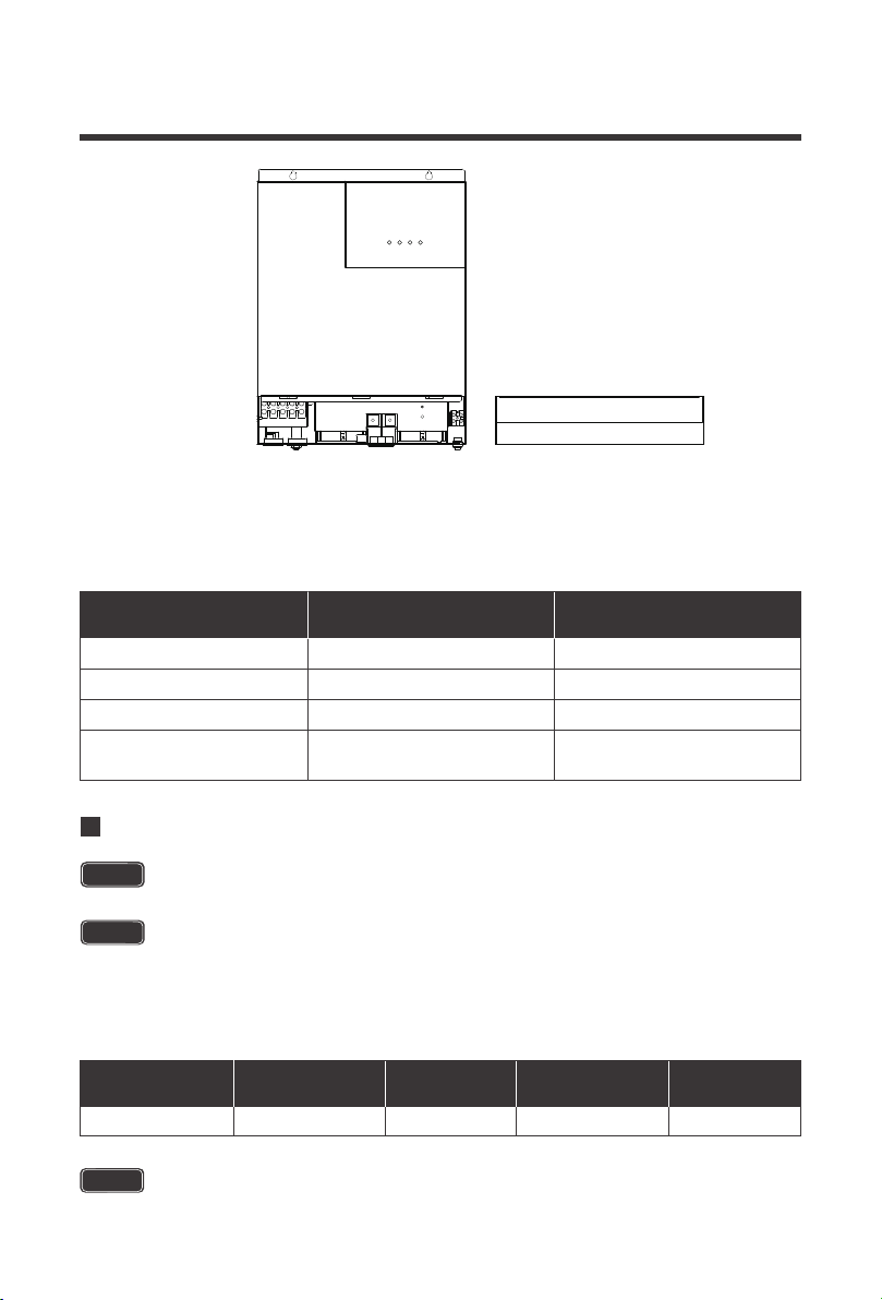
Identification of Parts
1. LCD Buttons
2. Mounting Holes
3. LCD Screen
4. LED Indicators
5. AC Input Breaker
6. Dry Contact Port
7. RS485/CAN Communication Port
8. USB Debugging Port (Internal Use)
9. AC Input Terminal
10. AC Output Terminal
11. Cooling Fans
12. PV Input Terminal
13. Main On/Off Power Switch
14. Battery Input Terminal
15. Grounding Lug
2
09
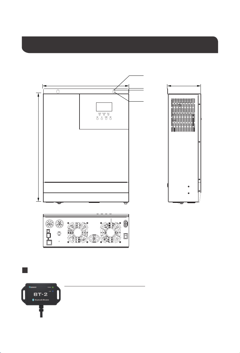
Dimensions
124mm322mm
6mm
426mm
16.8in
12.7in
φ0.2in
φ0.4in
0.2in
4.9in
Optional Components
φ6mm
φ11mm
The BT-2 Bluetooth module is a great addition to any Renogy charge
controllers with a RS485 port and is used to pair charge controllers with the
Renogy BT App. After pairing is done you can monitor your system and
change parameters directly from you cell phone or tablet. No more
wondering how your system is performing, now you can see performance
in real time without the need of checking on the controller’s LCD.
Renogy BT-2 Bluetooth Module:
10
Please read this manual carefully and familiarize yourself with the installation procedures
before installation.
Indicates a potentially dangerous condition. Use extreme caution
when performing this task.
Indicates a critical procedure for safe and proper operation of the
inverter.
Indicates a procedure or function that is important to the safe and
proper operation of the inverter.
NOTE
CAUTION
WARNING
Installation
Never install the inverter in a sealed enclosure with flooded batteries. Gas can
accumulate and there is a risk of explosion.
Cool, dry, well-ventilated area —
Heat is the worst enemy for electronic equipment.
Inverters must be in an area where the fans are not blocked or where they are not
exposed directly to the sun. They should be in an area free of any kind of moisture and
allow for clearance of at least 8” around the unit to provide adequate ventilation.
Protection against fire hazard —
the unit should be away from any flammable
material, liquids, or any other combustible material. The unit can spark and the
consequences could be severe.
Close proximity to battery bank—
prevent excessive voltage drop by keeping the unit
close to the battery bank and having a properly sized wire going from the battery bank
to the inverter.
Limiting electromagnetic interference (EMI)
— ensure the inverter is firmly grounded
to a building, vehicle, or earth grounded. Keep the inverter away from EMI receptors
such as TVs, radios, and other audio/visual electronics to prevent damage/interference
to the equipment.
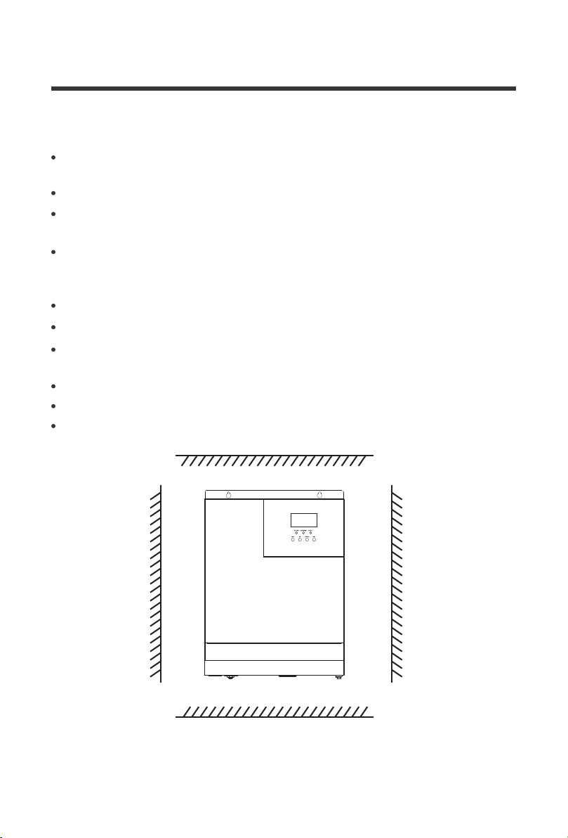
Location Recommendations
Ensure installation follows the following guidelines:
WARNING
WARNING
1.
2.
3.
4.
5.
Do not install the inverter in the same compartment as the battery bank
because it could serve as a potential fire hazard.
11
When installing the battery, be very careful, when installing lead-acid liquid batteries, you should
wear protective glasses, once in contact with battery acid, please wash with water in time.
Please Note:
While the Solar inverter has fans for cooling, this installation location optimal for
natural convection cooling will improve the overall efficiency .
Avoid placing metal objects near the battery to prevent short circuits in the battery.
Incorrect or improper connection points and corroded wires can cause great heat to melt the wire
insulation, burning surrounding materials, and even cause fire, so ensure that the connection is
tightened
Acid gas may be generated when the battery is charged so ensure good ventilation around
the environment.
It is best to avoid mobile applications when the wire shakes and cause the connection head loose.
Outdoor installation should avoid direct sunlight and rain, snow.
The municipal electrical input and AC output are high voltage, do not touch the wiring.
Do not touch the unit when the fan is working.
To avoid damage, do not use more than one (in parallel) input AC power supply.
Do not install the solar inverter in harsh environments such as damp, greasy, flammable and
explosive areas or where dust accumulation is high.
Other Precautions:
8inches / 200mm
8inches / 200mm
8inches
200mm
8inches
200mm
12
Wiring
NOTE
CAUTION
CAUTION
WARNING
WARNING
The Renogy Solar Inverter is suitable for 48V battery banks systems ONLY. Not
following the minimum DC requirement may cause irreversible damage to the unit.
The solar inverter components at the AC input/output, battery components, and
PV components will produce high energy output. Make sure to connect the
appropriate component to the appropriate labeled terminals.
Be careful of the positive and negative poles. Reversing the poles may cause
permanent damage to the inverter.
After the power switch is switched off, there is still high energy inside the solar
inverter, do not open or touch the internal device, wait for the capacitance to be
put off after the relevant operation.
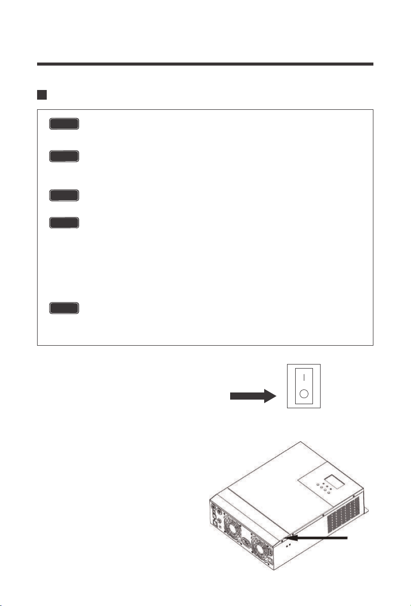
Locate the power button on the solar
inverter and make sure the solar inverter
main power is turned off
Remove the terminal cover by unscrewing
the appropriate terminals located on the
face of the solar inverter
The input terminals of the inverters have large capacitors connected to them.
Once a positive and negative wire are connected to the terminals, it will
complete the circuit, and commence drawing a heavy current momentarily. As
a result, there may be a sparking occurring even if the inverter is in the off
position. To minimize sparking, it is recommended that the user have the
appropriate size wire feeding into the solar inverters and/or install an external
fuse leading into the inverter.
ON
OFF
13
Wiring and installation methods must comply with national and local electrical specifications.
The following chart is reference only. Longer wire runs between solar panels and the solar
inverter as well as longer runs between the solar inverter and battery bank will require thicker
wiring size to minimize loss and improve system performance.
Be careful of the positive and negative poles. Reversing the poles may cause
permanent damage to the inverter.
The input terminals of the inverters have large capacitors connected to them. Once a
positive and negative wire are connected to the terminals, it will complete the circuit,
and commence drawing a heavy current momentarily. As a result, there may be a
sparking occurring even if the inverter is in the off position. To minimize sparking, it is
recommended that the user have the appropriate size wire feeding into the solar
inverters and/or install an external fuse leading into the inverter.
Specification Max Amps
Minimum Recommended
Wiring AWG
Battery Wiring
PV Wiring*
AC Input Wiring
AC Output Wiring
2AWG
4AWG
8AWG
8AWG
120A
80A
40A Max Bypass
30A Continuous
40A Max Bypass
Rated Battery
Discharge Current
Maximum Battery
Charging Current
Recommended
Wiring
Recommended
Circuit Breaker
Recommended
Ring Terminal
85A 120A 2AWG 2 pole, 140-160A 5/16”
Battery Wiring
NOTE
Make sure any circuit breakers are disconnected and ensure the unit is in the off
position.
NOTE
CAUTION
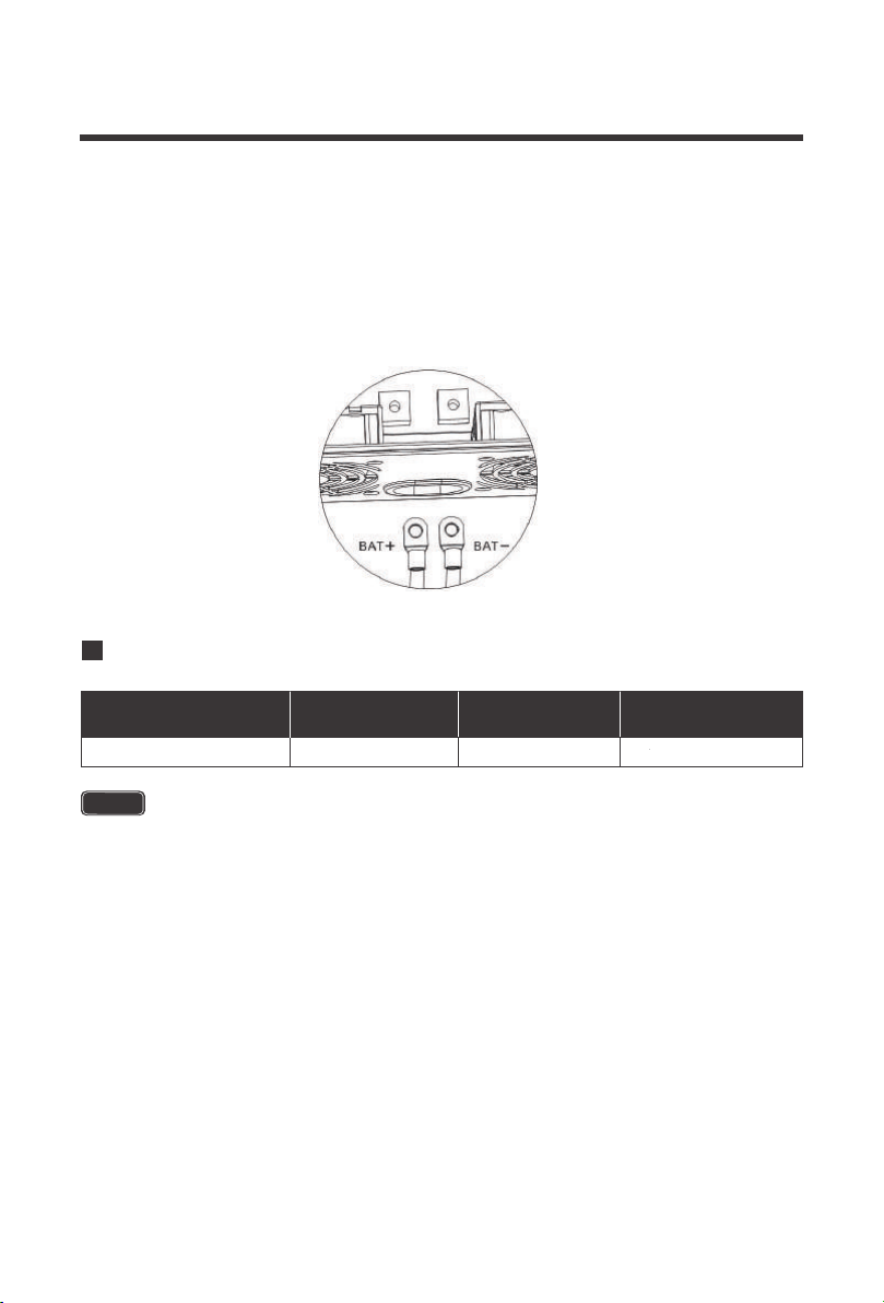
14
The solar inverter takes a 48V battery input to operate. This will require combining 12V or 6V
batteries in series to achieve the minimum voltage DC requirement. It is recommended to use
battery cables with ring terminals. The ring terminals must be firmly tightened and secured on
the respective battery terminals to prevent any excessive heating or resistance. Connect the
positive and negative battery ring terminals to the respective positive and negative battery
terminals on the solar inverter.
When combining panels in parallel it is recommended to use a combiner box for safety and
organizational precautions. The solar inverter accepts a maximum of 150VDC input and
requires a 48V battery input to operate. This will require combining solar panels in series or
series parallel to achieve the minimum voltage DC requirement. Due to many factors affecting
PV performance, it is recommended to utilize the open circuit voltage (Voc) when connecting
panels in series to make sure you stay under the 150VDC input. For parallel connections, it is
recommended to use the short circuit current (Isc) to make sure you are well under the 80A limit.
The bare wire terminal blocks must be firmly tightened and secured to prevent any excessive
heating or resistance. Connect the positive and negative PV wire to the respective positive and
negative PV terminal block on the solar inverter.
PV Wiring
Maximum PV
Charging Current
Recommended
Wiring
Recommended
Wiring
Recommended
Circuit Breaker
80A 4AWG 2 pole, 100A Bare Wire
For PV to charge 48V battery banks, you will need a minimum PV Voc voltage of
60VDC.
NOTE
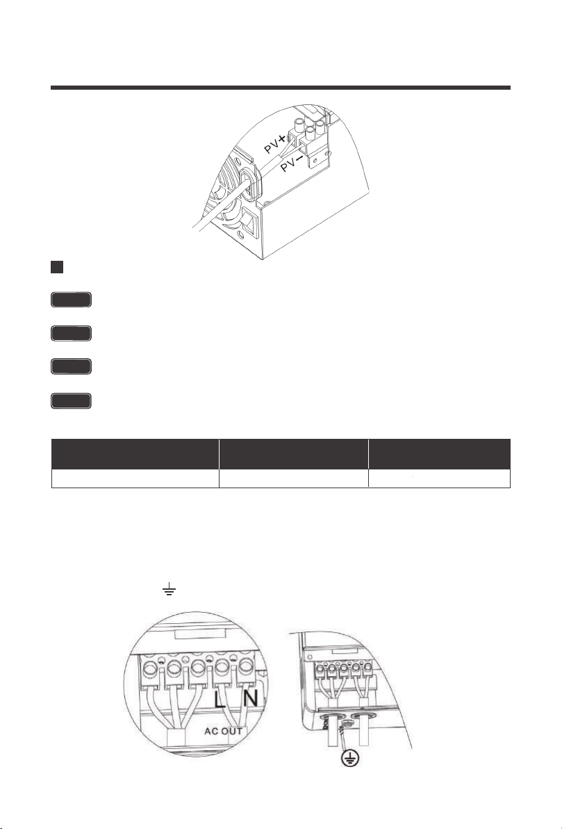
15
Carefully place the correct AC wire into the respective AC Output terminal block. The ground
output cable will need to be connected to the ground screw terminal located separately from the
output terminal block. It is recommended to keep ground as close as possible to the solar
inverter charger, the shorter the ground wire, the better. The order should be as follows:
AC Output Wiring
Maximum Inverter
Bypass Current
Recommended
Wiring
Recommended
Circuit Breaker
40A 8AWG 2 pole, 40A
Only the Live and Neutral wires will be connected to the Output Terminal Block, the
Ground will be connected to the screw terminal.
Make sure any circuit breakers are disconnected and ensure the unit is in the off
position.
There are two terminal blocks with “IN” and “OUT” markings. Please do NOT
misconnect input and output connectors.
AC Output should NEVER be connected to public power/utility or a generator.
NOTE
NOTE
WARNING
CAUTION
:Ground | L:Live | N:Neutral
16
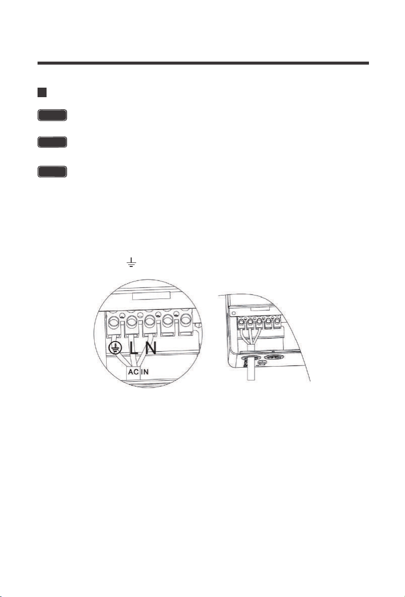
Run the AC input line through the AC input cable entry slot. Make sure to use appropriate cable
sizing when working with AC. Carefully place the correct AC wire into the respective AC Input
terminal block. The order should be as follows:
AC Input Wiring
The AC Input Terminal Block is connected to circuit breakers for added protection. Do
not modify or alter them as it may cause irreversible damage to the solar inverter.
The AC input must never be connected to the AC output as irreversible overload or
damage may result
NOTE
WARNING
There are two terminal blocks with “IN” and “OUT” markings. Please do NOT
mis-connect input and output connectors.
CAUTION
:Ground | L:Live | N:Neutral
17
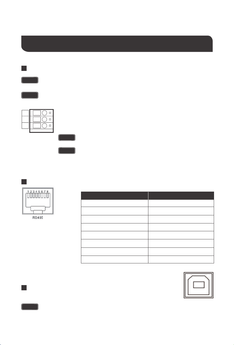
Communication Ports
Dry Contacts
RS485/CAN
USB
To use this to function, an auto start controller must be installed on the generator.
there are three contacts; up to down: NO, N, NC
NOTE
When using both USB and RS485, you can only use one of two alternatives, not use
both simultaneously .
NOTE
the NO-N contact can drive the resistive load of 125VAC/1A,
30DCV/1A
This port will be used for connecting to the BT-2 Accessory for
remote monitoring and control.
While the generator is connected, the unit now operates in
“Charging Mode” with the AC power from the Generator charging
the batteries as well as providing power to the AC loads.
The USB port is for internal purposes only. It will not be supported
as it requires proprietary information.
NOTE
NOTE
Do not store units with auto gen start feature enabled. Generators exhaust
dangerous fumes when running.
This contact automatically starts the generator and charges the battery bank.
Under normal conditions, this terminal is NC-N point closed, NO-N point
open. When the battery voltage reaches the low voltage point, the relay coil
is energized, and NO-N point now is closed and NC-N point now is open.
WARNING
1
2
3
4
5
6
7
8
5V
RS485-A
RS485-B
GND
NC
CAN_H
NC
CAN_L
Pin No. Parameter
NO
NC
N
18
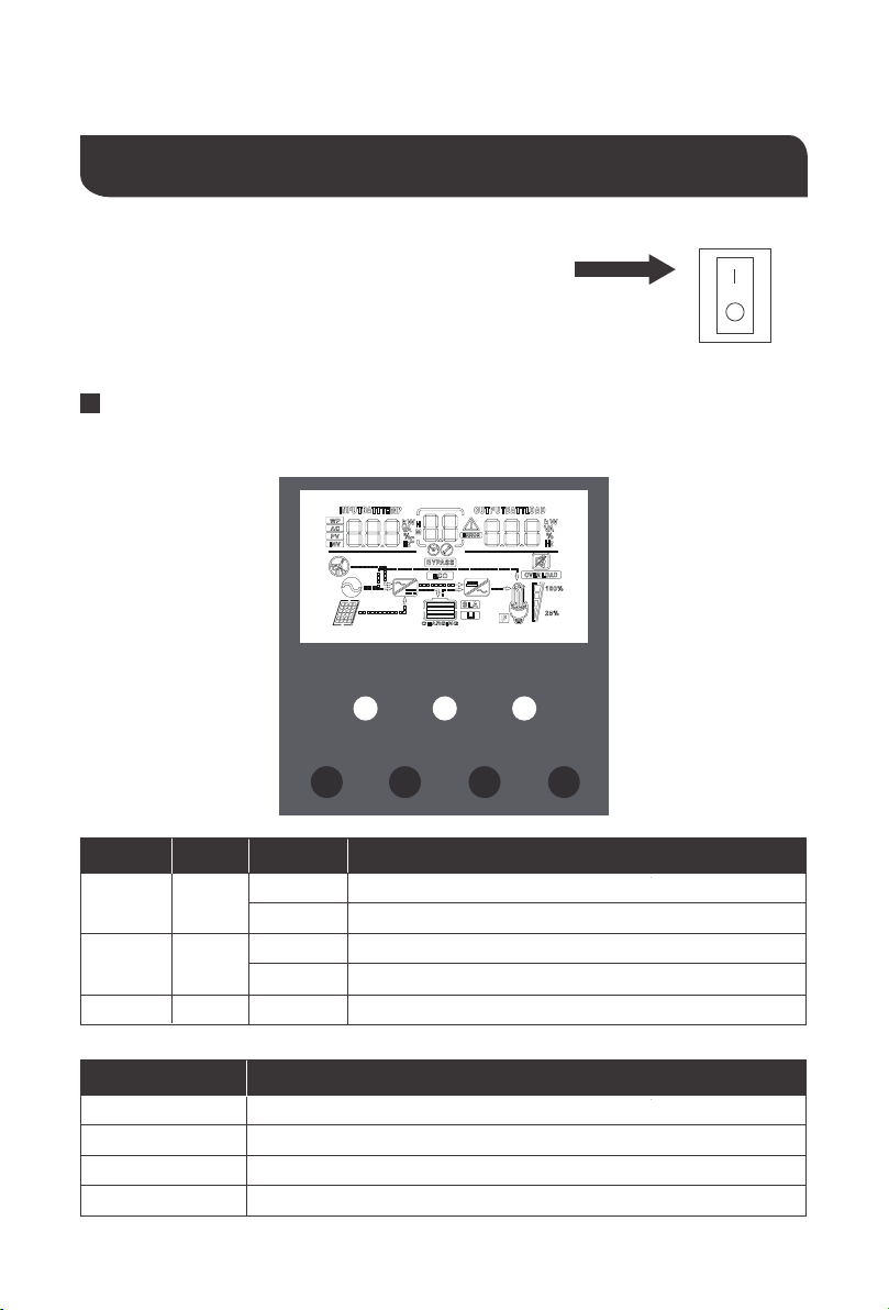
Assuming all connections are correct and tightly secured,
Locate the power button on the solar inverter and turn the
main power switch to the ON position.
The following describes the basic operation of the solar inverter charger
Operation
The solar inverter is equipped with 3 LCD indicators and 4 working buttons
LCD Operation
ON
OFF
LED Behavior ParameterColor
AC/INV
CHARGE
FAULT
Yellow
Green
Red
Solid
Solid
Solid / Flash
Flash
Flash
The output will be powered by the AC Line
The output is powered by battery or PV in battery mode
Battery is charging
Battery is fully charged
System fault
Key Parameter
SET
UP
DOWN
ENT
Go to / Exit Settings menu
Previous selection
Next choice
Under the Settings menu, determine/enter options
AC/INV CHARGE FAULT
SET UP DOWN ENT
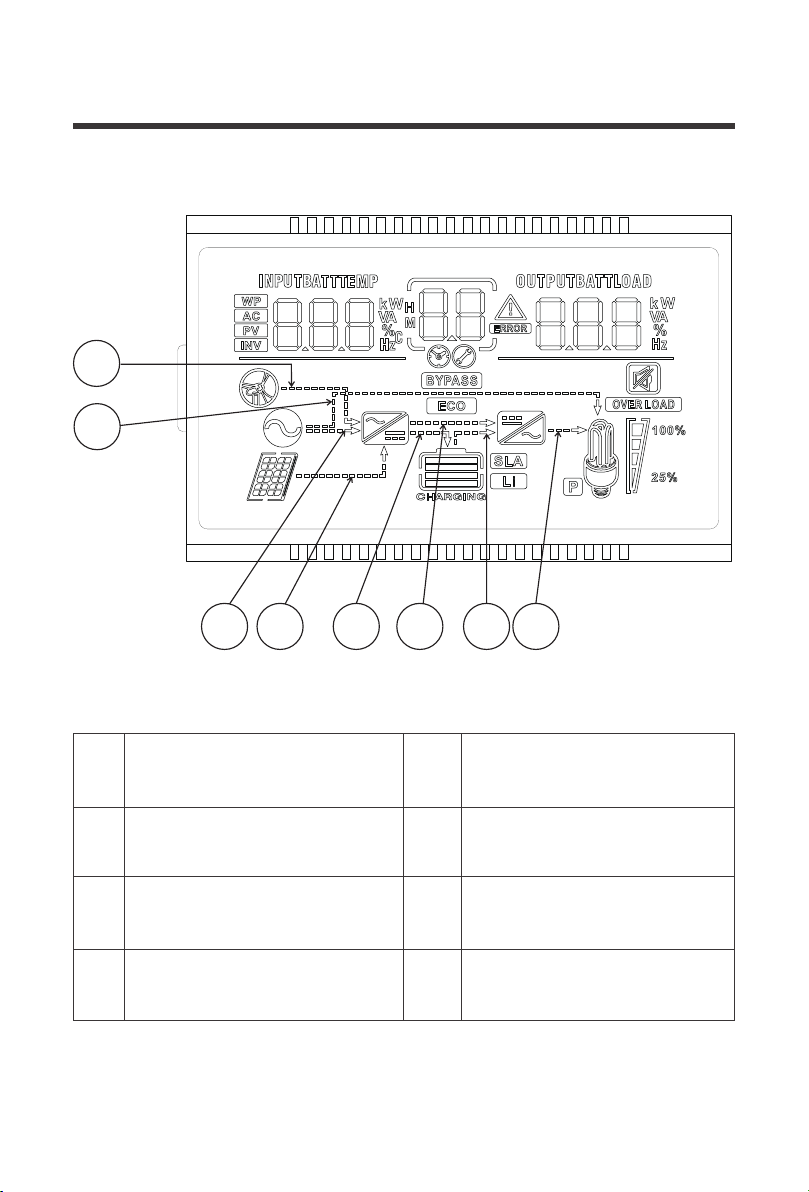
19
The arrow only displays during
startup and not part of the solar
inverter functionality
Indicates that the charging circuit
is charging the battery
1
Indicates that the power utility/grid
is powering the battery charging
circuit (AC-DC)
Indicates that the battery is
powering the inverter circuit
(DC-AC)
3
5
Indicates that the utility/grid is
powering the load
The arrow only displays during
startup and not part of the solar
inverter functionality
2 6
7
Indicates solar (PV) power to the
battery charging circuit (DC-DC)
Indicates that the inverter circuit is
powering the load
4 8
1
2
3
4
65 7 8
40
21
1
20
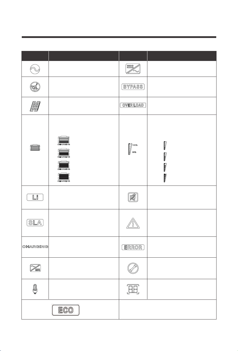
20
This icon indicates a wide
voltage AC input Mode (APL
mode)
Indicates that the solar inverter
charger is in the power bypass
(Bypass)
Indicates that the AC input is
connected to AC Source
Indicates that the inverter
mode circuit is working
Indicates that the PV input is
connected
Indicates that the inverter
circuit is powered to the load
Indicates that the current
battery type of the solar
inverter charger is lithium
Indicates that the buzzer is
not enabled
Indicates that the current
battery type of the solar
inverter charger is a sealed
lead acid
Indicates that an alarm has
occurred on the solar inverter
charger
Indicates that the battery is
charging
Indicates that the solar
inverter charger is in a faulty
state
Indicates AC/PV charging
circuit is working
Indicates that the solar
inverter charger is in set
mode
AC Load voltage output
When not in setting mode
displays alarm or fault code
Indicates that the solar
inverter charger is connected
to the battery. Status:
Indicates load percentage in
25% increments from the
overall wattage of the solar
inverter charger
Icon Function Icon Function
0 %~24%,
25%~49%,
50%~74%,
75%~100%
0 %~24%,
25%~49%,
50%~74%,
≥75%
Indicates the solar inverter is operating
under ECO power saving mode.
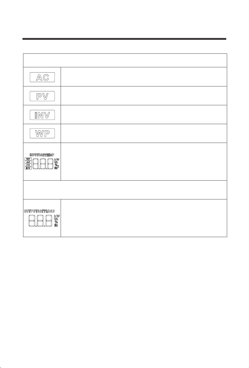
21
The following is on the left side of the LCD
Indicates AC input
Indicates PV input
Indicates inverter circuit
The icon appears only at startup and is irrelevant to functionality of the
solar inverter
The following is on the right side of the LCD
Shows battery voltage, total battery charge current, charge power, AC
input voltage, AC input frequency, PVInput voltage, internal heatsink
temperature, and software version
Indicates output voltage, output current, output power, output visual
power, battery discharge current, software version. In this setting
mode, the settings under the currently set parameter item code are
displayed
22
LCD Menu Screens
On the LCD home screen, press the "UP"and"DOWN" buttons to turn the page to view the solar
inverter’s real-time data.
Battery Input Voltage
PV Temperature
PV Input Voltage
Battery Input Current
Battery Input Kilowatts
AC Input Frequency
AC Input Voltage
Internal Parameters
Inverter Temperature
APP Software Version
Model PV Voltage Rating
Model Battery Voltage Rating
Load Output Voltage
PV Output Kilowatts
PV Output Current
Battery Output Current
Battery Output Kilowatts
AC Output Load Frequency
AC Output Load Current
Load Output KVA
Inverter Output Load Kilowatts
Bootloader Software Version
Model PV Power Rating
Model Output Current Rating
1
2
3
4
5
6
7
8
9
10
11
12
Fault
code

23
Press the "SET" key to enter parameter setting mode. After entering the settings menu, the
parameter number 00 flashes and you can press the "UP" and "DOWN" keys to select the
parameter code that you want to set. To access the parameter program press "ENT" key to
enter the parameter editing state, at which point the value of the parameter flashes. Adjusts the
value of the parameter through the "UP" and "DOWN" buttons, and finally press "ENT" to press
the key, complete the edit of the parameter, and return to the parameter selection state.
Parameters Number
Parameter Name Description
Set options
00
01
Exit
Load Working
Mode
02 Output Frequency
[00] ESC
[01] SOL
[01] UtI
(Default)
[01] SBU
[02] 50.0
[02] 60.0
(Default)
Exit the settings menu
Solar energy provides power to
the loads as priority. If solar
energy is not enough to power all
connected loads, battery energy
will supply power the loads at the
same time.
Utility provides power to the loads
only when any one condition
happens:
- Solar energy is not available
- Battery voltage drops to
low-level set-point in Program 04
Utility will provide power to the
loads as priority. Solar and battery
energy will provide power to the
loads only when utility power is
not available
The output frequency can be set
through this menu. By default, the
value should be 60Hz
Solar energy provides power to
the loads as priority. If solar
energy is not enough to power all
connected loads, battery energy
will supply power to the loads at
the same time.
Utility provides power to the loads
only when battery voltage drops to
low-level set-point in Program 04
LCD Programmable Features
03
AC Input
Voltage Range
[03] APL
[03] UPS
(Default)
By default, the input voltage range
is the same, 90~140VAC
By default, the input voltage range
is the same, 90~140VAC

24
Parameters Number
Parameter Name Description
Set options
04
06
44.0V
(Default)
[06] CSo
[06] Cub
Setting voltage point back to utility
source when selecting “SBU ” or
“SOL” in program 01. When the
voltage of the battery is lower than
this setting, the output switches
from inverting to the utility. The
setting range is from 39.6V - 52V,
in 0.4V increments.
Solar energy will charge battery
as priority. Utility will charge
battery only when solar energy is
not available
Utility will charge battery as
priority. Solar energy will charge
battery only when utility power is
not available
[06] SnU
(Default)
Solar energy and utility will charge
battery at the same time. MPPT
Solar energy will be priority
charging and when it is insufficient,
Utility will become priority. When the
photovoltaic energy is sufficient
again, Utility will stop charging
[06] oSo
Solar energy will be the only
charging source even if utility is
available
Battery Power to
Utility Setpoint
Battery Charging
Mode
Please Note: If
this
inverter/charger is
working in Battery
mode or Power
saving mode, only
solar energy can
charge battery.
Solar energy will
charge battery if
it's available and
enough
05
[05] 58.8V
(Default)
Setting voltage point back to
battery mode when selecting
“SBU” or “SOL” in program 01.
When the battery voltage is higher
than the setting value, the output
is switched from the utility to the
battery mode. The setting range is
48V - 58.8V, in 0.4V increments.
*Cannot be higher than [14]
Utility to Battery
Power setpoint
07
[07] 80A
(Default)
The maximum solar charging is
80A, the maximum Grid/Utility
charging is 40A (adjustable in
Program 28), totaling the
maximum current of 120A.The
range can be configured
between 0 ~ 120A
Maximum
charging current:
To configure total
charging current
for solar and utility
chargers. (Max.
charging current =
utility charging
current + solar
charging current)

25
Parameters Number
Parameter Name Description
Set options
[08] GEL
[08] FLd
[08]
LF14
LF15
LF16
Gel lead-acid battery, constant
voltage charging 56.8V,float
charging voltage 55.2V
Lithium iron phosphate battery
corresponding to 14 strings, 15
strings and 16 strings
Default constant voltage charging
voltage
14 strings: 50.4V
15 strings: 54V
16 strings: 57.6V
[08]
n14
n13
Default constant voltage charging
voltage
13 strings: 53.2V
14 strings: 57.2V
Lithium-ion battery corresponding
to 12 strings, 13 strings and 14
strings
Battery type
[08] SLd
(Default)
Sealed lead-acid/AGM battery,
constant voltage charging 58.4V,
float charging voltage 55.2V
08
[08] USE
User-defined, all battery
parameters can be set
Flooded lead-acid battery,constant
voltage charging 58.4V,float
charging voltage 55.2V
[09] 58.4
(Default)
Changes the charging voltage
setting, set the range 48V to 58.4V,
in 0.4V increments
Boost Charge
Voltage
*available in USER
and lithium setting
only
09
10
[10] 120 min
(Default)
Raise the boost charge time
setting, refers to the constant
voltage charging reached at
Program 09 . The range is 5min
to 900min, in 5 minute increments
Boost Charge
Duration
*available in USER
setting only
11
[11] 55.2V
(Default)
Floating charging voltage set
range 48V to 58.4V, in 0.4V
increments
Float Charge
Voltage
*available in USER
setting only

26
Parameters Number
Parameter Name Description
Set options
12
[12] 42V
(Default)
It is recommended to set this
voltage below the maximum
voltage the battery can withstand.
When this voltage is reached, the
loads will be powered off after a
time delay adjustable in Program
13 The range is 38V to 50V, in
0.4V increments
Low Voltage Load
Disconnect
*available in USER
and lithium setting
only
13
[13] 5S
(Default)
The following parameter sets the
delay-time after the battery
voltage is below the set-point in
Program 12. The set range is 5-50
seconds, in 5s increments
Battery
Over-discharged
Delay Time
**If a power
shortage occurs
and recovers in a
short time, it can
cause damage to
your connected
appliances. To
prevent this kind
of damage,
please check
manufacturer if
heavy load
appliances are
equipped with
time-delay function
before installation
*available in USER
and lithium setting
only
*available in USER
and lithium setting
only
14
[14] 43.8V
(Default)
Warning that the battery is
approaching low voltage. The output
does not shut down and the range is
40V to 52V, in 0.4V increments
Battery
Undervoltage
Alarm
*available in USER
and lithium setting
only
15
[15] 40V
(Default)
When the battery voltage goes
below this voltage set-point, the
solar inverter will immediately
disconnect and shut down
immediately. The set range is 36V
to 50V, in 0.4V increments
Battery Discharge
Limit Voltage
*available in FLD
and USER setting
only
*available in FLD
and USER setting
only
16
[16] DIS
[16] ENA
(Default)
Enables equalization charging
No equalization charging
Set Equalization
charging
17
[17] 59.2V
(Default)
Set equalization charging voltage.
The range is 48V to 59.2V, in 0.4V
increments
Battery
Equalization
Voltage

27
*available in FLD
and USER setting
only
*available in FLD
and USER setting
only
*available in FLD
and USER setting
only
*available in FLD
and USER setting
only
*Power-saving
Mode (ECO Mode)
Parameters Number
Parameter Name Description
Set options
18
[18] 120min
(Default)
Setting range is from 5min to 900
min. , in 5min increments
Battery
Equalization
Duration
19
[19] 240min
(Default)
Setting range is from 5min to 900
min, in 5min increments
Battery
Equalization
Time-Delay
20
[20] 30 days
(Default)
Setting range is from 0 days to 30
days, in 1 day increments
Stops equalization charging
immediately
Starts Equalization charging
immediately
Equalization
interval
21
[21] ENA
[21] DIS
(Default)
Enable
Equalization
Immediately
22
[22] DIS
(Default)
[22] ENA
Disables power-saving mode
Power-saving
Mode
After a 5min delay from setting, the
inverter will enter a power saving
mode and detect the load size.
Loads greater than or equal to 50W,
will be powered by the solar inverter.
Otherwise, it will automatically stay in
a low detecting mode and not power
any loads under 50W
23
[23] DIS
[23] ENA
(Default)
Overload automatic restart is
disabled, and the unit will not turn
on the loads
Enables automatic restart if the
load shutdown output has
occurred. The unit attempts to
restart the output after 3 minutes
and After 5 attempts the unit will
not longer resume to turn on the
loads
Overload
auto-start
24
[24] DIS
Over-temperature automatic
re-start is disabled
The over-temperature protection
is activated and upon temperature
dropping, the unit automatically
restarts
Overtemperature
auto-start
[24] ENA
(Default)

28
Parameters Number
Parameter Name Description
Set options
The range can be configured
between 0-40A
Supply for industrial frequency
transformer (disabled)
Supply for industrial frequency
transformer (enabled)
[28] 40A
(Default)
[29] DIS
(Default)
[29] ENA
28
29
Maximum AC
Charging Current
Split Phase
No alarm
Enable alarm
25
[25] DIS
Buzzer alarm
[25] ENA
(Default)
No alarm prompts when the status
of the primary input source
changes
Enable alarm prompts when the
status of the primary input source
changes
26
[26] DIS
Alarm
[26] ENA
(Default)
When disabled, the unit will not
transfer to Utility mode
When enabled, the unit will
transfer to Utility mode if overload
occurs in battery mode.
[27] DIS
[27] ENA
(Default)
27
Overload bypass:
When enabled,
the unit will
transfer to line
mode if overload
occurs in battery
mode.
35
[35] 50.4V
(Default)
Set point that recovers and
reconnects the solar inverter from
being disconnected in Low
Voltage Disconnect. The range is
from 44V -58.4V, in 0.4V
increments.
Low Voltage
Disconnect
Recover
36
[36] 80A
(Default)
Adjustable PV current settings.
The range is from 0 – 80A.
PV Charging
Current
37
[37] 52V
(Default)
When the battery reached at
floating status, it will need to be
lower than this setpoint before it
starts charging. The range is the
( Undervoltage Warning )~
( Floating Voltage – 1.2V )for
the respective battery
Battery Charging
Boost Return
Setpoint

29
Electronic Protections
Number
Protection Description
1
When the configured PV array charge current
exceeds the PV rated current, it will be charged at
the rated current
PV Current/Power
Limiting Protection
2
At night, the battery is prevented from discharging
through the PV component because the voltage of the
battery is greater than the voltage of the PV component
When the battery voltage reaches the overvoltage
disconnect point, the PV and the utility
automatically stop charging the battery, preventing
damage from overcharging the battery
When utility input is below 90VAC, charging is stopped
and the solar inverter is in inverter mode
PV Night anti-charge
protection
3
Triggered when AC Input voltage reaches 140V Overvoltage Protection
4
Power Input Under-
voltage Protection
5
Battery Over-voltage
Protection
When the battery voltage reaches the low voltage
disconnect voltage point, the battery discharge is
automatically stopped to prevent excessive discharge
of the battery from being damaged
6
Battery low-voltage
protection
When a short-circuit fault occurs at the load output, the
output AC voltage is immediately turned off and
outputs again after 1sec, for 3 more attempts. If they
fail, then the unit will need to be manually powered on
7
Load output
short-circuit protection
Output again after 3 minutes after overload
protection, overload 5 times in a row until the solar
inverter charger is powered back, with
A table of technical parameters after reference to
the load level and duration of the manual
9
Overload protection
When the battery discharge output current is
greater than the maximum and lasts 1 minute, the
AC input is loaded
13
Battery input
overcurrent protection
When the battery is reversed or the inverter is
shorted inside, the internal battery input fuse of the
inverter fuses to prevent battery damage or fire
14
Battery input protection
The inverter protects and stops when the external
battery port is shorted while the PV or AC is
charging stop the output current
15
Charge short-circuit
protection
When the internal temperature of the unit is too
high, the it will stop charging and discharging
8
Over-temperature
protection
Built-in AC input overcurrent protection circuit breaker
12
Bypass Flow Protection
Prevents battery power mode from inverting when
bypass is active
11
Bypass Protection
protection
Protection against reversing PV input connection
10
PV reverse polarity

30
Fault code
Fault name Description
【01】
Battery under-voltage alertBatVoltLow
【02】
Battery discharge current software protectionBatOverCurrSw
【03】
Battery not detectedBatOpen
【04】
Battery undervoltage stopdischarge alarmBatLowEod
【05】
Battery overcurrent hardware protectionBatOverCurrHw
【06】
Charge overvoltage protectionBatOverVolt
【07】
Bus overvoltage hardware protectionBusOverVoltHw
【08】
Bus overvoltage software protectionBusOverVoltSw
【09】
PV overvoltage protectionPvVoltHigh
【10】
Buck Overcurrent Software ProtectionPvBuckOCSw
【11】
Buck Overcurrent Hardware ProtectionPvBuckOCHw
【12】
utility power downbLineLoss
【13】
Side-by-side load protectionOverloadBypass
【14】
inverter overload protectionOverloadInverter
【15】
Inverted overcurrent hardware protectionAcOverCurrHw
【17】
Inverter short-circuit protection
-
Controller overtemperature protection
inverter over temperature protection
Fan failure
Memory failure
Model settings are wrong
InvShort
【18】
-
【19】
OverTemperMppt
【20】
OverTemperInv
【21】
FanFail
【22】
EEPROM
【23】
ModelNumErr
-
-
Error between AC output and bypass
-
-
Internal battery boost circuit failure
【24】
-
【25】
-
【26】
RlyShort
【27】
-
【28】
-
【29】
BusVoltLow
【16】
--
Fault Codes

31
Maintenance
Fault
Solutions
Make sure the battery is properly connected and charged to
be able to recognize the solar inverter.
or click any button on the screen to exit screen sleep mode.
Screen not displaying
Measure whether the battery voltage exceeds 60Vand
disconnect the photovoltaic array from and the power-on.
Rechargeable battery
overvoltage protection
Wait until the battery is charged to return to above the low
voltage recovery voltage.
Battery undervoltage
protection
Disconnect or reduce any loads from the unit. Shut down the
solar inverter charger and turn on again to clear the error.
Inverter short-circuit
protection
Check with the meter if the PV input voltage is above the
maximum allowable input voltage of 145 V operating voltage.
PV overvoltage
Check that the battery is not connected or that the battery
side circuit breaker is not closed.
Battery missed alert
When the temperature of the equipment cools to, normal
charge and discharge control is restored.
Over-temperature Protection
(1) Reduce the use of electrical equipment;(2) restart the
solar inverter charger and load recovery output.
Overload Protection
Check that the fan is not turning or is blocked by something else.Fan failure
In order to maintain optimal long-term performance, it is recommended to perform inspections
of the following items twice a year.
1. Make sure that the air flow around the solar inverter is not blocked and remove any dirt or
debris from the radiator.
2. Check all terminals to see if there is corrosion, insulation damage, high temperature or
combustion / discoloration signs, tighten the terminal screws.
Danger of electric shock! Make sure that all power supplies on solar inverter disconnected and
that all capacitive power is released before checking or operating accordingly!
WARNING
32
Utility/Grid
110/120Vac
(90Vac~140Vac) ±2%
50Hz/ 60Hz (auto detect)
47-0.3Hz x 55-0.3Hz (50Hz);
57-0.3Hz x 65-0.3Hz (60Hz);
Breaker
>95%
10ms
Yes
40A
Rated input Voltage
Input voltage range
Frequency
Frequency range
Overload / Short circuit Protection
Efficiency
Conversion time
(Bypass and reverse)
Reverse Flow Protection
Max Bypass Current load
Inverter
Pure Sine Wave
3500
3500
1
120Vac
±5%
>90%
(102%<load<110%)±10%:
turn off the output after 5min;
(110%<load<125%)±10%:
turn off the output after 10sec;
(125%<load)±10%:
turn off the output after 5sec;
Waveform
Rated Output (VA)
Rated Output (W)
Power factor
Output AC Voltage
Unstable Input Error
7000VAPeak power
2HPMotor Capability
BreakerOutput Short-circuit Protection
40ABypass Breaker Specifications
48V (minimum start-up voltage 44V)Rated Battery Voltage
40.0Vdc~60Vdc ± 0.6VdcBattery voltage range
Power Saving Mode Self-Consumption
No Load Self Consumption
Output Frequency (Hz)
Efficiency
Overload protection
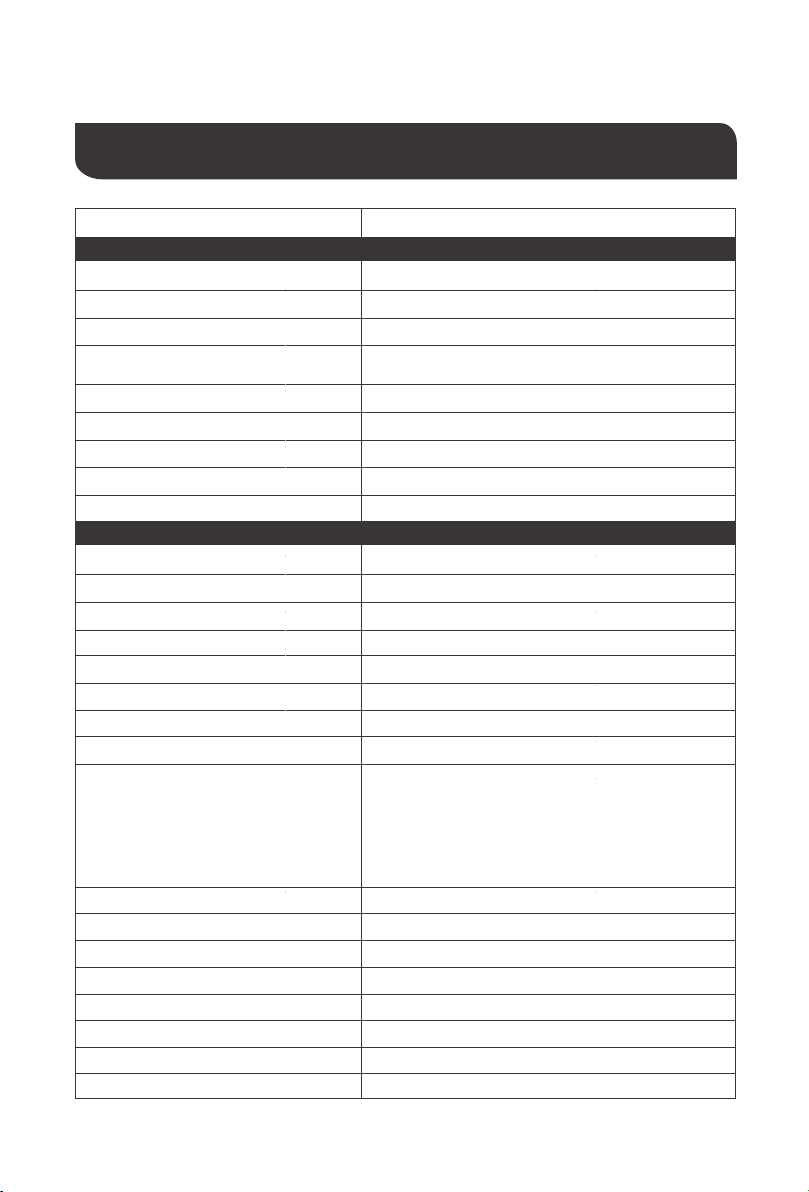
Technical Specifications
50Hz ±0.3Hz 60Hz ± 0.3Hz
<25W
48W
Model RIV4835CSH1S
33
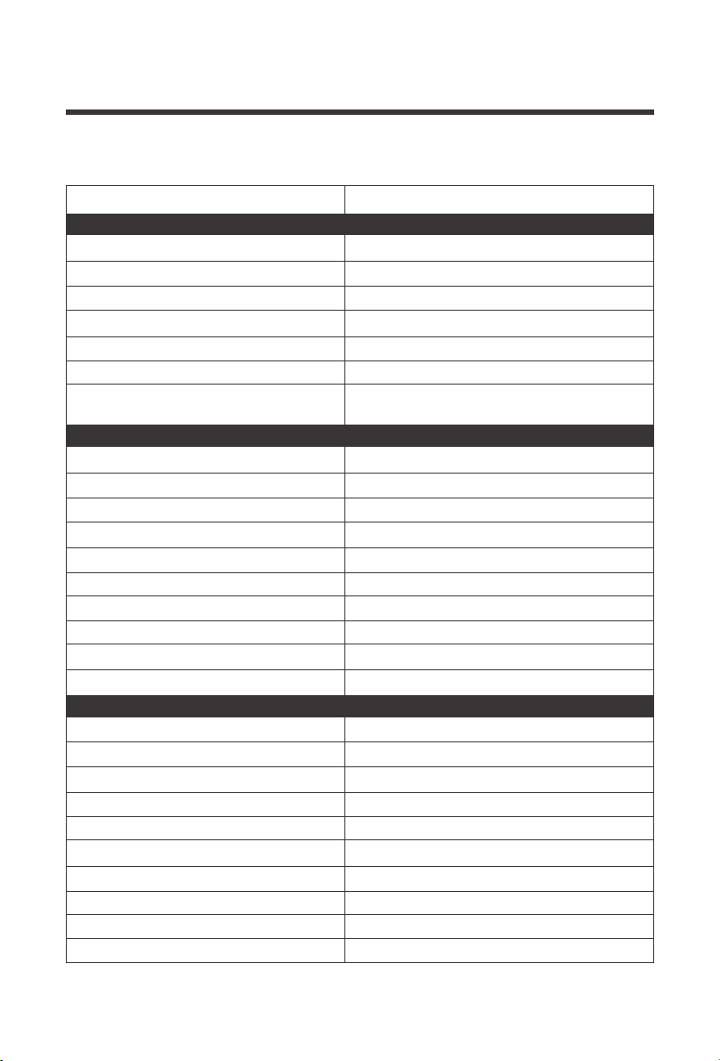
Utility/Grid Charging
Lead Acid or Lithium
40A
± 5Adc
40 –60Vdc
Breakers and fuses
40A
Yes; Automatically alerts and then turns off
charging after1 minute
Battery type
Maximum Charging Current (AC)
Unstable Condition Error
Charging Voltage Range
Short-circuit protection
Circuit Breaker Specifications
Overcharge Protection
General
FCC Part 15 Class B, RoHS
5°F ~ 131°F/ -15°C ~ 55°C
-13°F ~ 140°F / -25°C ~ 60°C
5% to 95% (three-layer paint protection)
≤60dB
Fans
Certifications
Operating Temperature
Storage Temperature
Humidity
Noise
Cooling
16.8*12.7*4.9 in / 426*322*124 mmDimensions (L-W-D)
23.8 lbs /10.8kgWeight
Solar (PV) Charging
145Vdc (150 VDC Actual)
60-145Vdc
60-115Vdc
40-60Vdc
4200W
4400W
0-80A
80A
Internal Fuse
Recommended PV Max
PV Operating Voltage
MPPT Voltage Range
Battery Charging Range
Maximum Output Power
Maximum Input Power
Maximum Input Current
PV Charging Current Range
Short-circuit Protection
Reverse Polarity
Wiring Protection
Model RIV4835CSH1S
IP Grade IP 20
I
Safety Class
34
When modifying parameters in User Mode, the following rules must be followed to set parameters
successfully.
If setting the Low Voltage Disconnect in User Mode, it must always be at least 2V lower than
the Low Voltage Disconnect Recovery Voltage
Overvoltage Disconnect > Overvoltage Disconnect Recover ≥ Equalization voltage ≥ Boost voltage
≥ Float voltage
Overvoltage Disconnect > Over Voltage Disconnect Recover
Low Voltage Disconnect Recover > Low Voltage Disconnect (at least 2V Smaller) < Discharge
Limit Voltage
Undervoltage Recover > Undervoltage Alarm
Over Voltage
Disconnect
Over Voltage
Disconnect Recover
Battery type
Parameters
USER
(Default)
Flooded
Lead Acid
(FLD)
Custom Range
SLD/
AGM
GEL
Non-Lithium Battery Parameters
Equalization
Voltage [16]
Boost Voltage
[09]
Under Voltage
recover
Low Voltage
Warning [14]
Low Voltage
Disconnect
Recover [35]
Low Voltage
Disconnect
[12]
Discharge Limit
Voltage [15]
58.2V
Over-discharge
Delay Time [13]
Float Voltage
[11]
60V
58.2V
60V
58.2V
59.2V
60V
58.2V
60V
N/A
44.8V 44.8V 44.8V 44.8V N/A
50.4V
50.4V 50.4V
50.4V
(adjustable)
N/A
58.4V 56.8V 58.4V
58.4V
(adjustable)
48~58.4V
55.2V 55.2V 55.2V
55.2V
(adjustable)
48~58.4V
43.8V 43.8V 43.8V
43.8V
(adjustable)
40~52V
42V 42V 42V
42V
(adjustable)
38~50V
40V 40V 40V
40V
(adjustable)
36~50V
5S 5S 5S
5S
(adjustable)
5~50S
120
minutes
120
minutes
120
minutes
120 minutes
(adjustable)
5~900 minutes
59.2V
(adjustable)
48~59.2V
N/A
Equalization
Duration [18]
Equalization
Interval [20]
Boost Duration
[10]
- -
120
minutes
120 minutes
(adjustable)
5~900 minutes
- -
30
days
30 days
(adjustable)
0~30 days
- -
NOTE
1.
2.
3.
4.

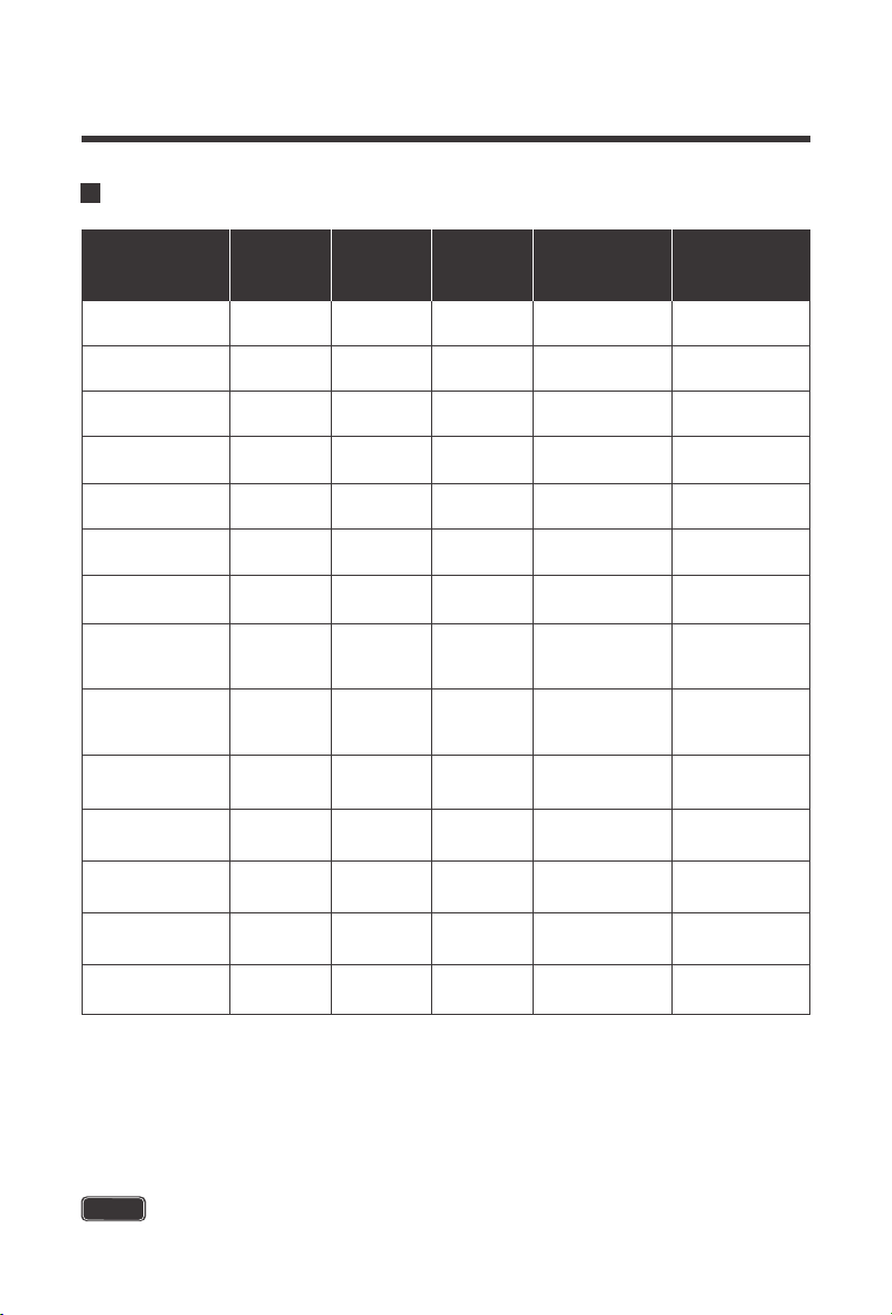
Lithium Battery Parameters
35
Battery type
Parameters
Over Voltage
Disconnect
Lithium-ionLithium Iron Phosphate
Custom
Range
Over Voltage
Disconnect
Recover
58.2V
48~58.4V
N/A
40~52V
Equalization
Voltage
[16]
-
Float
Voltage
[11]
-
Under
Voltage
Recover
49.6V
Undervolt
age
Alarm[14]
48.8V
(adjustable)
Low Voltage
Disconnect
Recover
[35]
54V
(adjustable)
N/A
Low Voltage
Disconnect
[12]
60V
38~50V
Discharge
Limit Voltage
[15]
-
-
48~58.4V
48~59.2V
N/A
N/A
Boost
Voltage
[09]
57.6V
(adjustable)
48V
(adjustable)
36~50V
45.6V
(adjustable)
5~50s
30s
(adjustable)
5~900
minutes
(LF16)
Over-
discharge
Delay Time
[13]
Equalization
Duration
[18]
Equalization
Interval
[20]
0~30
days
58.2V
-
-
45.6V
44.8V
(adjustable)
48.8V
(adjustable)
60V
-
-
57.2V
(adjustable)
42V
(adjustable)
39.2V
(adjustable)
30s
(adjustable)
(n14)
Variable
until Full
USER
(Default)
58.2V
59.2V
(adjustable)
55.2V
(adjustable)
44.8V
44V
(adjustable)
50.4V
(adjustable)
60V
58.4V
(adjustable)
42V
(adjustable)
40V
(adjustable)
5s
(adjustable)
120minutes
(adjustable)
30days
(adjustable)
120Minutes
(adjustable)
Variable
until Full
58.2V
-
-
46.4V
45.6V
(adjustable)
50.4V
(adjustable)
60V
-
-
54V
(adjustable)
44.8V
(adjustable)
42.8V
(adjustable)
30s
(adjustable)
(LF15)
Variable
until Full
(LF14)
60V
58.2V
-
-
43.6V
42.8V
(adjustable)
47.2V
(adjustable)
-
-
50.4V
(adjustable)
42V
(adjustable)
40V
(adjustable)
30s
(adjustable)
Variable
until Full
-
60V
58.2V
-
-
-
53.2V
(adjustable)
42.4V
41.6V
(adjustable)
38.8V
(adjustable)
36.4V
(adjustable)
30s
(adjustable)
45.2V
(adjustable)
(n13)
Variable
until Full
Boost
Duration
[10]
5~900
minutes

36
When modifying parameters in User Mode or Lithium, the following rules must be followed to set
parameters successfully.
If setting the Low Voltage Disconnect in User Mode, it must always be at least 2V lower than
the Low Voltage Disconnect Recovery Voltage
Overvoltage Disconnect > Overvoltage Disconnect Recover ≥ Equalization voltage ≥ Boost voltage
≥ Float voltage
Overvoltage Disconnect > Over Voltage Disconnect Recover
Low Voltage Disconnect Recover > Low Voltage Disconnect (at least 2V Smaller) < Discharge
Limit Voltage
Undervoltage Recover > Undervoltage Alarm
NOTE
1.
2.
3.
4.

3333333337
Charging Parameters Glossary
Overvoltage Disconnect—
When and if the charge controller experiences a voltage
higher than what is assigned, it will disconnect itself from the circuit; ceasing charge.
Overvoltage Recover--
in the event a charge controller experiences an over-voltage
condition set by the previous parameter, then this reconnecting parameter is put into
play to direct the controller when it can connect and safely charge again. Typically
over-voltage reconnection is achieved when time has passed (ex. The sun setting), or
when the over-voltage condition is remedied ultimately reducing the voltage to a user
defined charging voltage.
Equalization Voltage--
equalization voltage is a corrective over-charge of the battery.
The user should consult their battery manufacturer regarding specific battery
equalization capacity. This parameter sets the equalization voltage to set the battery at
when it reaches the equalization state.
Boost Voltage--
users should check with their battery manufacturer for proper charging
parameters. In this stage, users set the boost voltage where the battery will reach a
voltage level and remain there until the battery undergoes an absorption stage.
Float Voltage--
once the charge controller recognizes the set float voltage, it will
commence floating. The battery is supposed to be fully charged in his state, and the
charge current is reduced to maintain battery stability levels.
Undervoltage Recover--
deals with the loads connected to the system. When batteries
are determined to be low due to them approaching low voltage disconnect, then the loads
will be shut off to give the batteries time to recover. This parameter sets the controller to
shut off the loads until it can reach the low voltage reconnect stage.
Undervoltage Alarm--
this parameter deals with the batteries themselves approaching
the under-voltage recovery state. The user should minimize loads before the charge
controller approaches a level where it will do this automatically to protect the battery from
discharging.
Low Voltage Recover--
parameter allows loads connected to the system will be able to
operate (not fully) again.
Low-voltage disconnect--
prevents over-discharge of the batteries by automatically
disconnecting any loads. This extends battery life and is the precedent to being in an
under-voltage state, recovering from the undervoltage state, and finally reconnecting to
normal operational state.

3434343438
This equipment has been tested and found to comply with the limits for a class B digital device, pursuant to
part 15 of the FCC Rules. These limits are designed to provide reasonable protection against harmful
interference in a residential installation. This equipment generates, uses and can radiate radio frequency
energy and if not installed and used in accordance with the instructions, may cause harmful interference to
radio communications. However, there is no guarantee that interference will not occur in a particular
installation. If this equipment does cause harmful interference to radio or television reception, which can be
determined by turning the equipment off and on, the user is encouraged to try to correct the interference
by one or more of the following measures:
This device complies with Part 15 of the FCC Rules. Operation is subject to the following two conditions:
(1) this device may not cause harmful interference, and (2) this device must accept any interference
received, including interference that may cause undesired operation.
·
Reorient or relocate the receiving antenna.
·
Increase the separation between the equipment and receiver.
·
Connect the equipment into an outlet on a circuit different from that to which the receiver is connected.
·
Consult the dealer or an experienced radio/TV technician for help.
Discharging limit Voltage--
This parameter ensures that the controller does not exceed
the default or assigned parameter before needing to be charged again. This is put into
play to optimize and extend the battery life by going with a higher voltage. The lower the
discharge limit voltage the more negative effect on battery efficiency.

Renogy reserves the right to change
the contents of this manual without notice.
RENOGY.COM
US
2775 E Philadelphia St, Ontario, CA 91761, USA
909-287-7111
www.renogy.com
support@renogy.com
https://www.renogy.cn
support@renogy.cn
CN
400-6636-695
苏州高新区科技城培源路1号5号楼-4
CA
https://ca.renogy.com
supportca@renogy.com
https://au.renogy.com
supportau@renogy.com
AU
JP
https://www.renogy.jp
supportjp@renogy.com
https://uk.renogy.com
supportuk@renogy.com
UK
https://de.renogy.com
supportde@renogy.com
DE