2000W/3000W
Version 3.0
Pure Sine Wave Inverter & Charger
PCL
SERIES

01
CONTENTS
Identification of Parts
Dimensions
Included Components
Location Recommendations
Sizing A Battery Bank
Grounding
DC WIRING
AC WIRING
Automatic Neutral-to-Ground Bond Switching
Automatic Transfer Relay
Auto Generator Start
Fan Operation
Main Menu
05 Setup Battery Type
05 Custom Battery Type /User Mode
Display Panel
LCD Display Icons and Behaviors
01 Utility Priority and Battery Priority
03 AC Input Voltage Range
04 Power Saving Mode
07 Auto Restart Temperature Fault
09 Output Frequency
11 Maximum Utility Charging
12 Low Battery Voltage Setpoint
13 Over-Voltage Battery Recovery
18 Alarm Control / Behavior
19 Screen Mode
20 LCD Screen Mode
04
05
05
07
07
09
09
10
10
11
12
13
15
15
16
16
16
20
21
22
23
26
26
27
28
28
28
29
29
29
29
30
30
30
31
31
31
31
32
32
32
33
33
34
34
35
36
37
General Information
Product Overview
Installation
Operation
Programmable Features
Battery Charging Stages
Fault / Warning Codes
Technical Specifications
22 Normal Mode Sound
25 Record Fault Code
26 Boost Charging
27 Float Charging
29 Low DC Cut-off Voltage
93 Input Frequency Range
94 Selection of Battery Type Custom
95 Battery High Voltage for Dry Contacts
96 Low Voltage Trip for Dry Contacts
97 Dry Contact Control
98 Low Battery Voltage Alarm
99 AC output Voltage
02
Important Safety Instructions
Please save these instructions.
This manual contains important safety, installation, and operating instructions for the
inverter. The following symbols are used throughout the manual:
Inverter Safety
The inverters are suitable for 12V Battery Banks ONLY.
ALWAYS make sure inverter is in OFF position and disconnect all AC and DC
connecting when working on any circuit associated with the inverter.
NEVER connect the AC output of the unit directly to an Electrical Breaker Panel/ Load
Centre which is also fed from the utility power / generator.
When connecting battery terminals, ensure the polarity of the battery connections is
correct. Incorrect polarity may cause permanent damage to the unit.
Be careful when touching bare terminals of capacitors as they may retain high lethal
voltages even after power is removed.
Installation and wiring must comply with the Local and National Electric Codes (NEC)
and must be done by a certified technician.
Read all of the instructions and cautions in the manual before beginning the installation.
There are no serviceable parts for this inverter. Do NOT disassemble or attempt to repair
the inverter.
Make sure all connections going into and from the inverter are tight. There may be
sparks when making connections, therefore, make sure there are not flammable
materials or gases near installation.
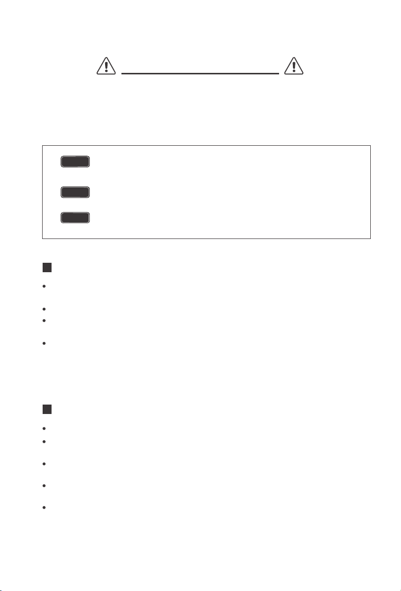
Indicates a potentially dangerous condition. Use extreme caution
when performing this task.
Indicates a critical procedure for safe and proper operation of the inverter.
Indicates a procedure or function that is important to the safe and
proper operation of the inverter.
NOTE
CAUTION
WARNING
General Safety Information

03
Do NOT let the positive (+) and negative (-) terminals of the battery touch each other.
Use sealed Lead-Acid, Flooded, Gel, AGM, Lithium or Calcium batteries which must be deep cycle.
Explosive battery gases may be present while charging. Be certain there is enough
ventilation to release the gases.
Be careful when working with large lead acid batteries. Wear eye protection and have
fresh water available in case there is contact with the battery acid.
Over-charging and excessive gas precipitation may damage the battery plates and
activate material shedding on them. Too high of an equalizing charge or too long of one
may cause damage. Please carefully review the specific requirements of the battery
used in the system.
Battery Safety
The unit should be installed in a well-ventilated, cool, and dry environment. Make
sure the fans of the unit and the ventilation holes are not blocked.
Do not expose the unit to rain, moisture, snow, or liquids of any type.
Installation Safety

04
General Information
Key Features
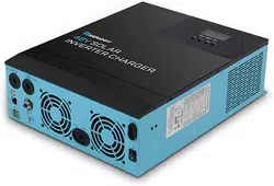
The Renogy PCL series inverter-chargers combine an inverter and battery charger with an
automatic transfer switch into one complete system. Featuring a 3-stage battery charging
mode when connected to utility AC power, the PCL series inverter-charger can meet
powerful demand needs as well as charge your battery bank. As a power supply, it is
capable of producing cleaner, smoother, and more reliable electricity for a user's electronic
needs. Take full advantage of the multiple features.
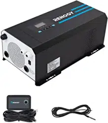
Robust and sleek design
LCD and LED display used to view inverter status and programming features
Offers high quality waveform with little harmonic distortion
4-Stage battery charger with configurable charging current
8 Pre-Set battery voltages including Lithium; User-defined option available
Automatic generator start option
Peak efficiency >90%
Multiple electronic protections
05
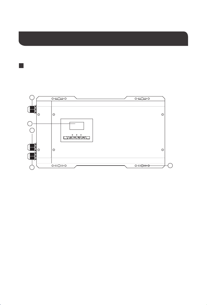
Top view
1
2
3
5
4
Product Overview
Identification of Parts
AC Input Cable Entry
AC Output Cable Entry
Wired Remote Control
Cable Entry
LCD Panel and Buttons
Mounting Holes
1.
2.
3.
4.
5.
06
15
16
7
17
18
11
9
10
8
13
12
14
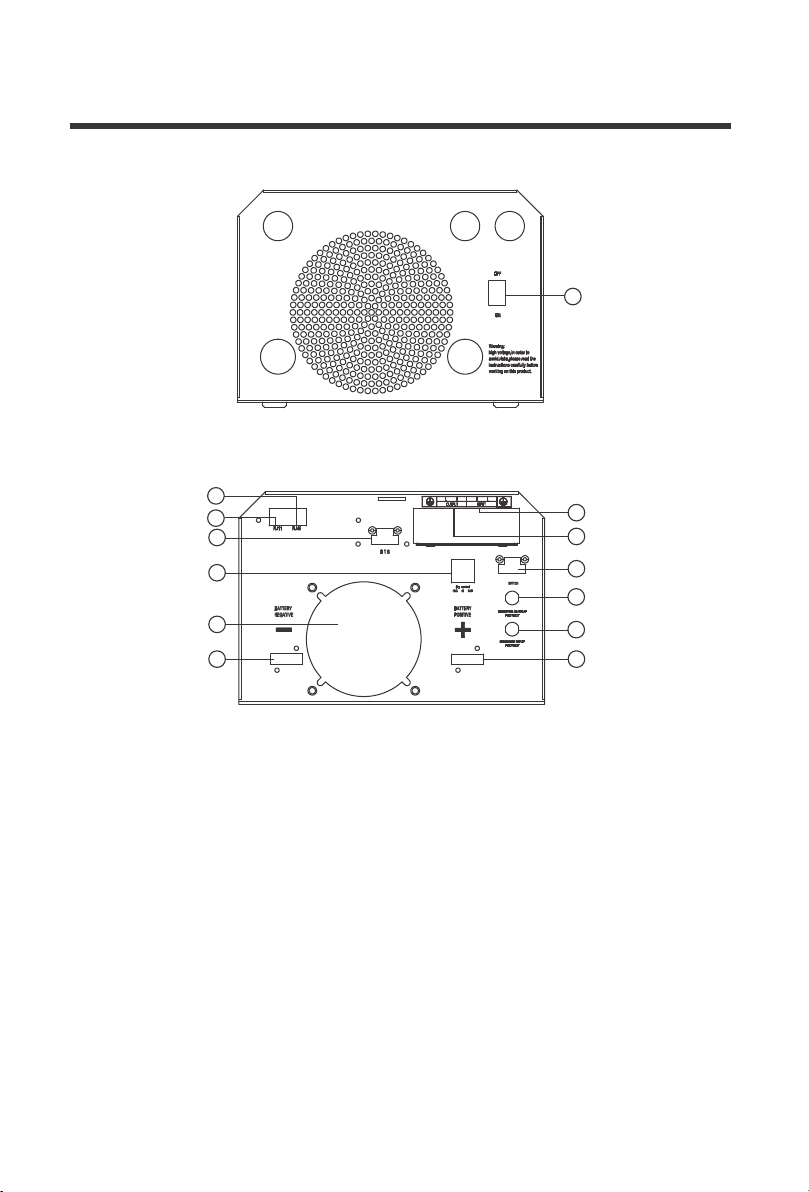
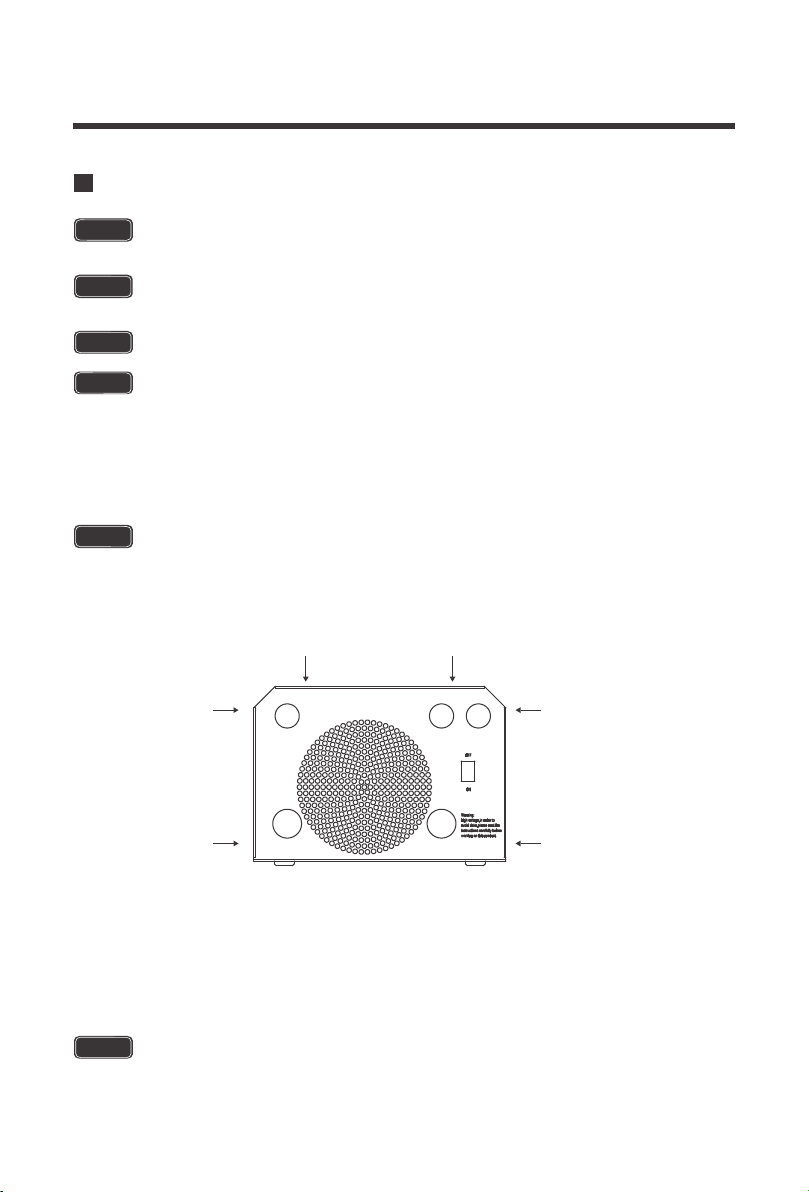
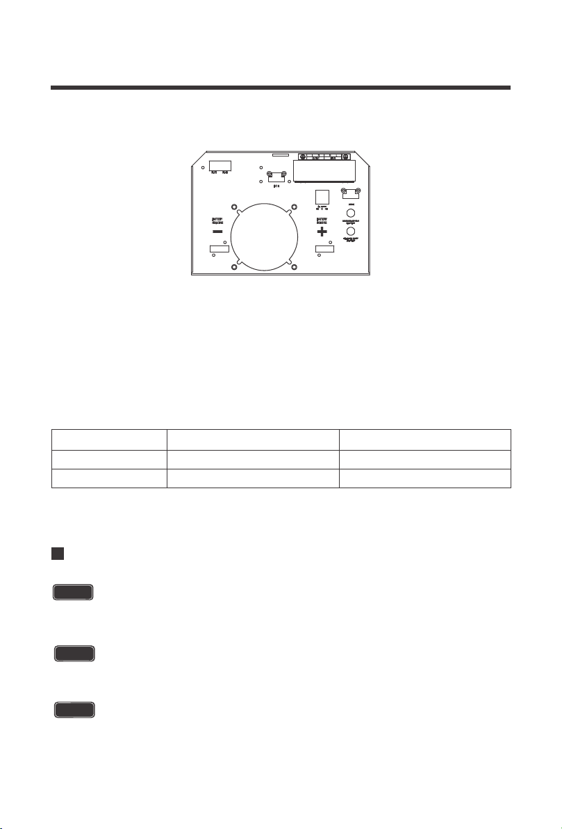
Left View (Uncovered)
6
Left View (Covered)
Main ON/OFF Switch: This is a simple
ON/OFF switch to be able to control the
inverter with the plate in place. The
wiring is connected to the Terminal Block
on the inside of the plate seen in 13.
RJ11 Port: Port for connecting Wired
Remote Control
Dry Contact Relay Port: NC, C, NO ports
for connecting generators and making
use of the Auto-Gen Start feature.
Battery Temperature Sensor Port:
Non-polarity sensitive port that connects
the included temperature sensor to the
PCL unit.
DC Negative Battery Terminal
Rj45 Port for Future Development
AC Output Terminal Block
AC Input Terminal Block
Main Power Switch Terminal Block
Inverter Output Protection Circuit Breaker
Inverter Input Protection Circuit Breaker
DC Positive Battery Terminal
Fans that dissipate heat
6.
7.
8.
9.
12.
11.
10.
13.
14.
15.
16.
17.
18.
07
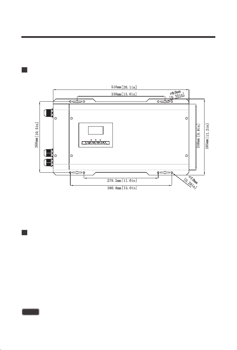
Dimensions
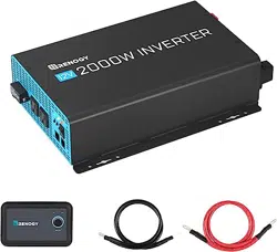
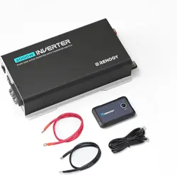
Included Components
Battery Temperature Sensor (BTS)
Renogy inverter chargers come equipped with a 9.9 ft / 3 meter battery temperature sensor
that will help prolong the battery life. The battery sensor allows the inverter charger to
continuously adjust the charging voltage based on the battery temperature. The inverter
charger will compensate charging with a factor of -0.5mV/C◦ per degree after 77F°/25C°,
within -40C°/F° ~ 176F°/80C°.The sensor should be installed on all battery banks except for
lithium. Simply connect the wire into the terminal block (it is not polarity sensitive), if it is not
connected already. The terminal block may need to be tightened onto the respective BTS
port. Then place the sensor near the battery bank for automatic temperature compensation.
Connect the temperature sensor for all batteries except Lithium for best charging accuracy
NOTE
Note: Dimensions are in millimeter[inches]

08
Make sure the PCL is in the off position in order to use the wired remote control correctly.
The wire remoted control for the inverter chargers gives users the opportunity to power
on/off the inverter from a distance. Giving you approximately 16.4ft of distance, simply
connect the cable to the RJ11 port on the PCL unit. Make sure both the PCL inverter model
and the wired remote are both in the off position. The you will be able to turn on the inverter
charger via remote power switch.
NOTE
Wired Remote Control
Never install the inverter in a sealed enclosure with flooded batteries. Gas can
accumulate and there is a risk of explosion.
The inverter should never be mounted vertically on a vertical surface since it would
present a hazard for the fan opening which is crucial for cooling the inverter.
Cool, dry, well-ventilated area —
Heat is the worst enemy for electronic equipment.
Inverters must be in an area where the fans are not blocked or where they are not hit
directly by the sun. They should be in an area free of any kind of moisture and allow for
clearance of at least 10” around the unit to provide for adequate ventilation.
Protection against fire hazard —
the unit should be away from any flammable
material, liquids, or any other combustible material. The unit can spark and the
consequences could be severe.
Close proximity to battery bank—
prevent excessive voltage drop by keeping the unit
close to the battery bank and having a properly sized wire going from the battery bank
to the inverter.
Limiting electromagnetic interference (EMI)
— ensure the inverter is firmly grounded
to a building, vehicle, or earth grounded. Keep the inverter away from EMI receptors
such as TVs, radios, and other audio/visual electronics to prevent damage/interference
to the equipment.
Secure inverter
—the inverter could be stand alone or mounted using the outlying
terminals on the inverter.
Installation
Location Recommendations
Ensure installation follows the following guidelines:
CAUTION
CAUTION
WARNING
WARNING
WARNING
WARNING
Make sure inverter is in the off position before connecting anything.
Do not over-torque or over tighten the terminals. This could potentially
damage the unit.
Refer to the technical specifications for max wire sizes on the controller
and for the maximum amperage going through wires.
1.
2.
3.
4.
5.
6.
Do not install the inverter in the same compartment as the battery bank
because it could serve as a potential fire hazard.
09
Example
A Microwave oven
= 700 Watts
12V battery bank
700 Watts to run microwave oven using the batteries as
if it was a 12VDC microwave requires 58 Amps
700 Watts / 12 Volts = 58 Amps
Now that amps have been determined, the amp-hours
need to be determined. The microwave will be used for
approximately 3 hours a day.
58 Amps * 3 hours =
174 Ah
At least a 174 Ah battery must be selected in order to use the 700-Watt microwave at 3
hours a day. However, determining a battery size is also dependent on the battery that
is able to handle repeated discharge/charge cycles.
Load Operation = 3 hours
Determine the amount of Watts (Amps * Volts) for the load, and how long the load
needs to operate—
each electrical appliance has technical specificationsindicating the
watts, or the volts and amps required for operation.
Estimate load run-time—
Battery size depends on load watts and run-time. Most loads
are not constant, so estimation is very important.
Utilize the formula Watts = Volts * Amps
Determine Amps used for how many hours – Amp-hour (Ah)
Sizing a Battery Bank
Grounding
For this Renogy inverter, the battery bank will be 12 volts direct current (12 VDC)
This is just an example. Actual quantities vary by battery capacity and rates of
discharge.
NOTE
To power the microwave in the example, the user may need to us an inverter that is
1400W or more depending on surge and power factor..
NOTE
10
Grounding for the PCL Inverter-chargers could be to a metal frame of an RV. The
connections to ground must be tight and against bare metal. Whether using the inverter in a
mobile application, such as an RV or in a building, grounding is highly recommended. The
recommended wire size for grounding is 8 AWG copper wire. For more information
regarding grounding, users and/or installers must consult with the Local and National
Electric Codes (NEC) for more specific grounding regulations and suggestions as they can
change per scenario.
11
Flip inverter power to the “OFF’ position
Unscrew the screw terminals along the edge of the side plate
Gently remove DC Side plate to expose DC Terminals
Connect the positive and negative DC Cables to their respective terminals and run them
through the side panel
The Terminals must clean to reduce the resistance in the cable connection. A
buildup of dirt or oxidation may eventually lead to the cable terminal overheating
during periods of high current draw
DC WIRING
The Renogy Pure Sine Wave Inverters are suitable for 12V battery bank systems ONLY.
Not following the minimum DC requirement will cause irreversible damage to the unit.
WARNING
WARNING
CAUTION
Be careful of the positive and negative poles. Reversing the poles might cause
permanent damage to the inverter. It will surely blow the internal fuse.
NOTE
Damage to the Renogy inverters due to reverse polarity is NOT covered by warranty.
NOTE
NOTE
The input terminals of the inverters have large capacitors connected to them. Once
a positive and negative wire are connected to the terminals, it will complete the
circuit, and commence drawing a heavy current momentarily. As a result, there may
be a sparking occurring even if the inverter is in the off position. To minimize
sparking, it is recommended that the user have the appropriate size wire feeding into
the inverters and/or install an external fuse leading into the inverter.
Ensure all sources of DC power (i.e., batteries, solar, etc.) and AC power (utility
power or AC generator) are de-energized (i.e., breakers opened, fuses removed)
before proceeding—to prevent accidental shock.
To Access the main panel, unscrew the terminals on the outside of the side panel.
1.
2.
3.
4.
12
AC WIRING
WARNING
When installing DC cables, the following are recommendations:
Battery positive and negative cables should be as close to the battery as possible to
minimize voltage loss and other possible effects.
Tie, tape, or twist cables together to reduce self-inductance.
Install all overcurrent devices on the positive cable.
1.
2.
3.
Model
2000W 200A 2/0
3000W 300A 4/0
Recommended Fusing Recommended Wire Sizing
CAUTION
Avoid switching on the inverter with the load (electronic devices) already switched
on. This may trigger an overload since some electronic devices have an initial high
power surge to start.
CAUTION
When switching off the inverter, turn off the electronic devices first. Although the
inverter is off, the capacitors will still have a charge, so the DC and AC terminals must
be disconnected if altering the circuitry.
Ensure all sources of DC power (i.e., batteries, solar, etc) andAC power (utility power
or AC generator) are de-energized (i.e., breakers opened, fuses removed) before
proceeding—to prevent accidental shock
13
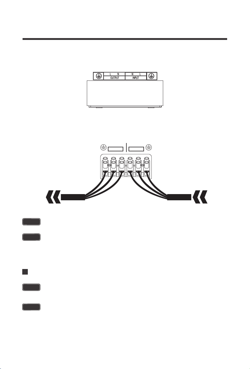
2.Make note of the AC output terminals from left to right (Ground, Live, Neutral) and the AC
Input terminals from left to right (Neutral, Live, Ground).
1.Remove the AC Terminal block
WARNING
The AC input must never be connected to the AC output as irreversible overload or
damage may result
WARNING
AC Output should NEVER be connected to public power or a generator
Automatic Neutral-to-Ground Switching
CAUTION
Be careful of the positive and negative poles. Reversing the poles might cause
permanent damage to the inverter. It will surely blow the internal fuse.
Damage to the Renogy inverters due to reverse polarity is NOT covered by warranty.
NOTE
OUTPUT
AC OUTPUT AC Input
L N
INPUT
LN
14
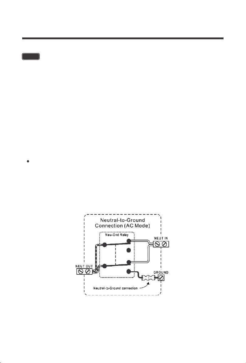
When in the Pass-Through Mode / Utility Mode, the Neutral of the 120VAC shore power will be
connected to the Neutral Out connector of the Inverter Charger.This will ensure that the
Grounded Conductor (GC) / Neutral of the shore power is bonded to the Earth Ground at one
single point at the location of the AC Power Distribution System of the Marina / RV Park.
The automatic transfer switch will take care of automatic neutral to ground bonding in the
following scenarios:
The input terminals of the inverters have large capacitors connected to them. Once a
positive and negative wire are connected to the terminals, it will complete the circuit,
and commence drawing a heavy current momentarily. As a result, there may be a
sparking occurring even if the inverter is in the off position. To minimize sparking, it
is recommended that the user have the appropriate size wire feeding into the
inverters and/or install an external fuse leading into the inverter charger.
NOTE
Feeds utility / shore power to the battery charger Section when shore power / utility is
available.
This cannot be disabled.

NOTE
NOTE
15
Automatic Transfer Relay
Auto Generator Start
The PCL inverter chargers are equipped with a 30A transfer relay switch that switches between
Inverter and Standby mode depending on availability of AC input power. If AC is present, the
transfer relay bypasses up to 30A of the incoming AC power through the inverter to power the
AC loads on the inverter’s output. In the event AC power gets disconnected, the inverter will
power the loads through the battery bank.
The PCL inverter charger series have functions to automatically start and stop a generator for
supplementing charge. The Auto Generator feature starts the Generator with the use of
Normally Closed (NC) contacts of the relay that “opens” when the battery voltage drops to the
programmed value of Program 96, Low Battery Voltage Set-point. The Normally Open (NO)
relay “closes”, and the auto generator start commences the generator to start charging the
battery bank. When the battery is recharged and its voltage rises to the programmed value of
Program 95, High Battery Voltage Set-point The NC (closes) contacts and NO (open) contacts
of relay reset and the Generator will stop / shut down the Generator automatically. The PCL unit
will then transfer back to “Inverting Mode”.
The inverter’s internal AC transfer relay contacts are rated for 30 amps (each leg), the
pass-through current for relay contact must be no greater than 30 amps or damage
to this relay may occur.
To use this to function, an auto start controller must be installed on the generator.
there are three contacts; left to right: Normally Closed (NC) Common (COM),
Normally Open (NO).
NOTE
While the generator is connected, the unit now operates in “Charging Mode” with the
AC power from the Generator charging the batteries as well as providing power to the
AC loads.
Do not store units with auto gen start feature enabled. Generators exhaust
dangerous fumes when running.
WARNING
WARNING
16
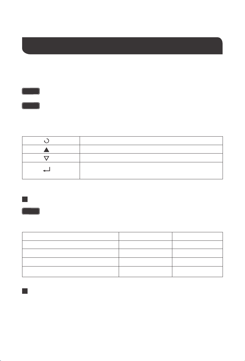
FAN Operation
Main Menu
By default, when first powering the unit the fans and alarm will run for approximately
1 minute as part of the start-up routine. Other fan ON/OFF operation parameters are
listed below:
Condition
Inverter Mode Load Percentage
DC Input Current
Inverter Heat Sink Temperature
Turn on Condition
Current ≥ 10A
Uptime ≤ 1 minute
Load ≥ 35%
Temperature ≥50℃
Turn off Condition
Current < 6A
Uptime > 1 minute
Load < 35%
Temperature < 45℃
Inverter Charger Uptime
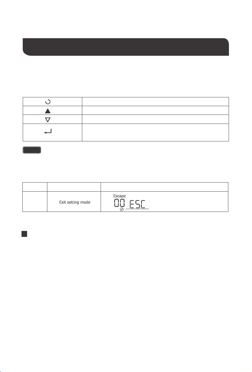
Exit setting mode, go back to main menu
1. Hold down to enter Parameter setting menu.
Cycle through the menu
Cycle through the menu
2. Tap to change/confirm setting in parameter setting menu
Function Keys
Upon successful connection of a 12V deep cycle battery bank, flip the inverter power to the ON
position.
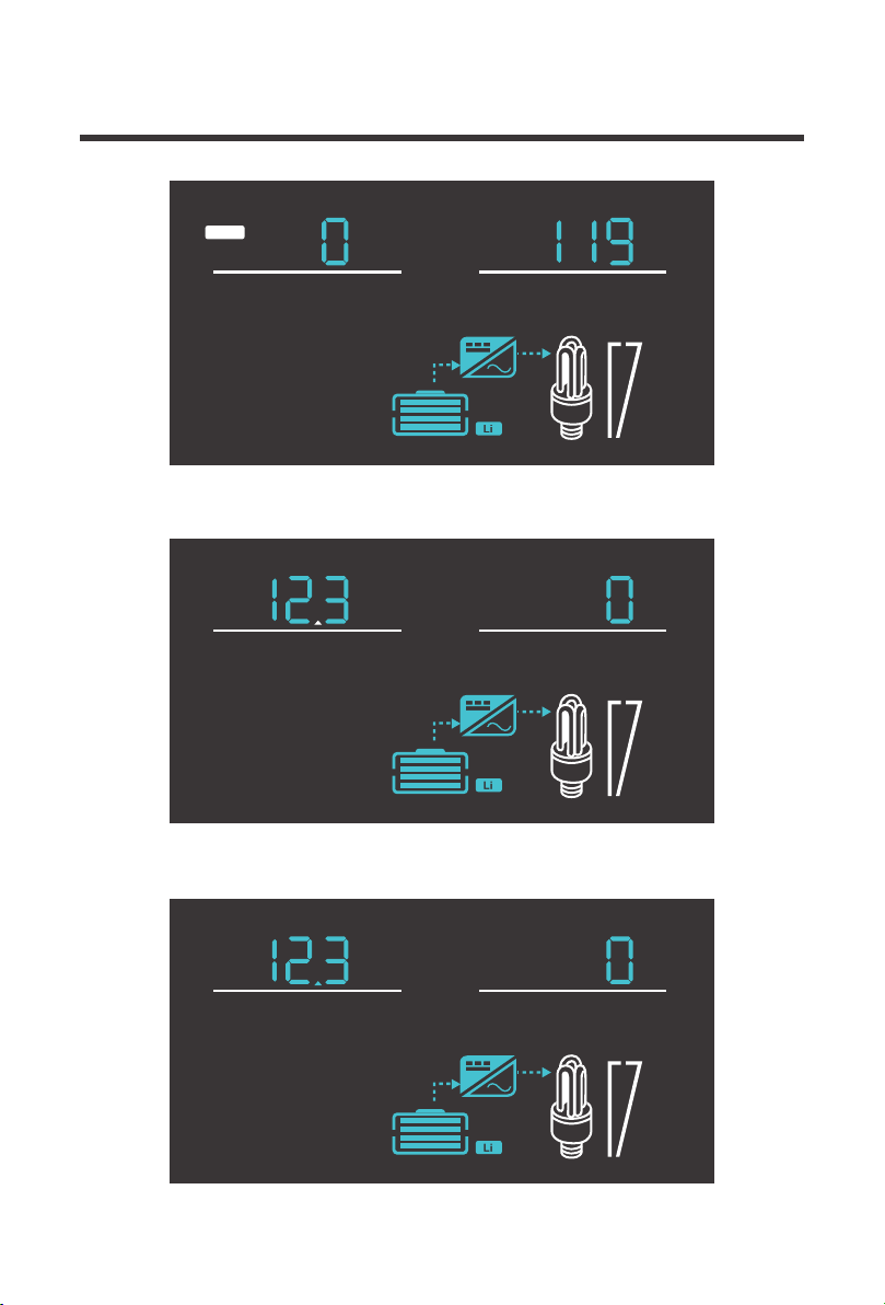
Use the up and down arrows to cycle through the menu. The following is what is displayed:
NOTE
NOTE
Upon successful connection of a 12V deep cycle battery bank, flip the inverter power
to the ON position.
NOTE
The unit may also be powered on by the wired remote control.
Operation
17
100%
25%
V
OUTPUT
V
INPUT
AC
100%
25%
VA
OUTPUT
V
BATT
100%
25%
W
OUTPUT
V
BATT
Input Volts AC / Output Volts AC
Battery Volts DC / Load Volts AC
Battery Volts DC / Output Watts
18
100%
25%
Hz
OUTPUT
V
BATT
100%
25%
V
OUTPUT
Hz
INPUT
AC
100%
25%
%
OUTPUT
V
BATT
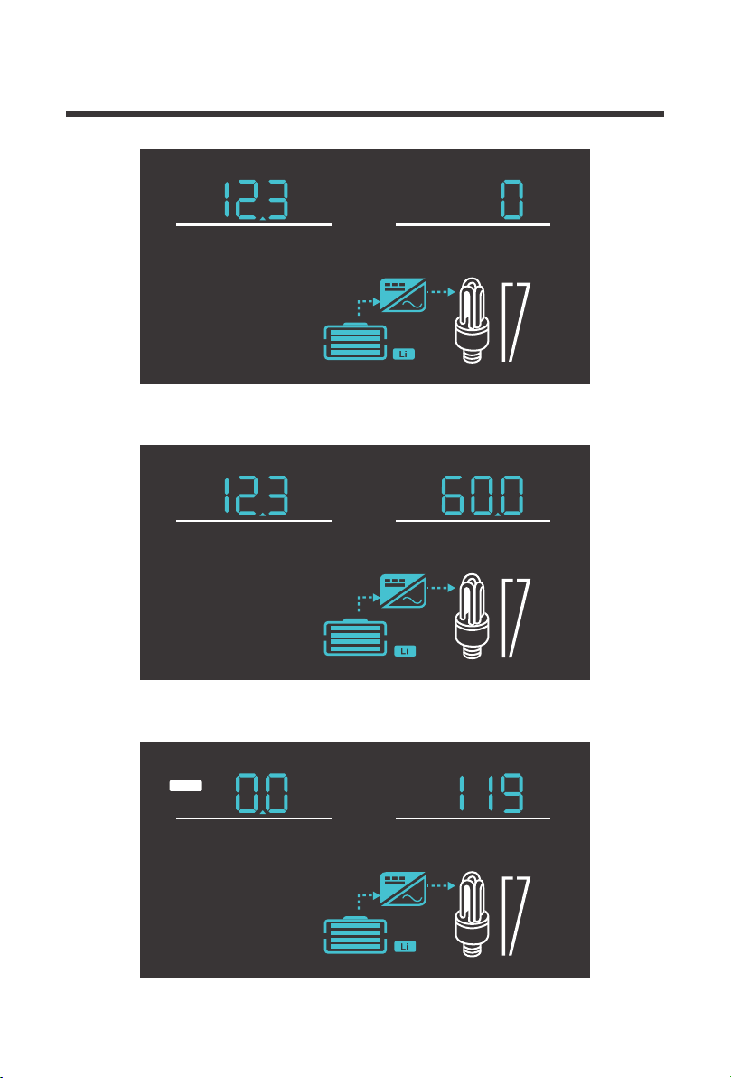
Battery Volts DC / Output Load %
Battery Volts DC / Output Frequency
Input Frequency / Output Volts AC
19
100%
25%
AV
INPUT
AC
100%
25%
V
OUTPUT
O
C
TEMP
100%
25%
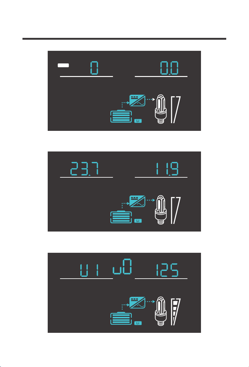
Input Volts AC / Input Amps
Inverter Temperature Celsius / Output Volts AC
Inverter Version Number
20
05 Setup Battery Type
A.G.M.2
Calcium
De-sulphation
14.6 13.7
14.4 13.6
14.4 13.8
14.8 13.8
15.1 13.6
15.5 for 4 hrs
Gel 2
Type of battery
14.0 13.7
A.G.M.1
14.1 13.4
Gel 1
For Charging to be
accurate, Temperature
Sensor must be connected.
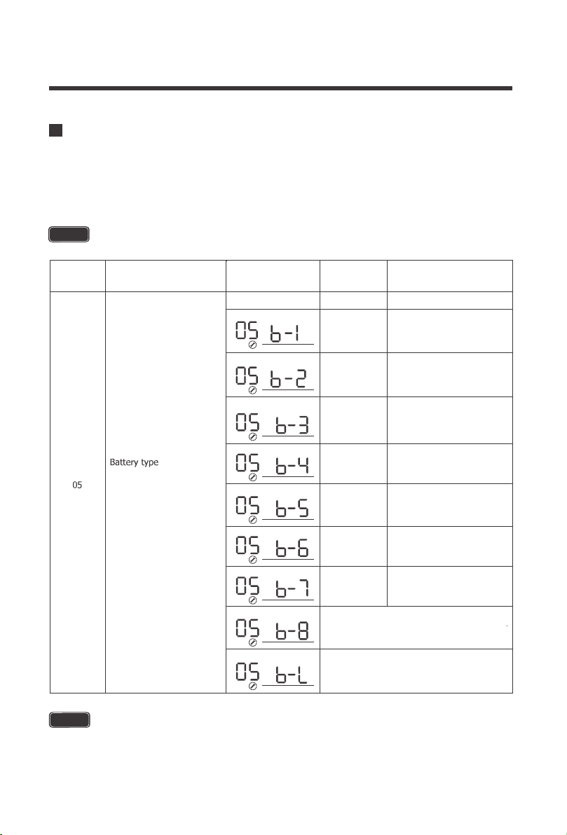
The PCL inverter charger series is fully programmable. The minimum programming needed to
get started would be to set the battery type. Press and hold the parameter setting key to enter
parameter setting mode. Use the arrow keys to go to Program 05. Use the following table to set
the appropriate battery type based on the boost voltage and float voltage that has been preset.
The PCL series is only compatible with 12V battery banks.
NOTE
Lithium charging is preset to 14.7V charging. When charging the battery and it
reaches the 14.7V setpoint it will stop charging the battery. Upon normal use, when
the voltage of the battery drops down to 12.4 and below, charging will resume.
NOTE
Program
Number
Parameter
Setting
Description
Boost
Voltage
Float
Voltage
When battery voltage reaches 14.7V
charging will stop. When battery voltage
drops below 12.5V charging will resume.
Sealed Lead Acid
Open Lead Acid / Flooded
Li
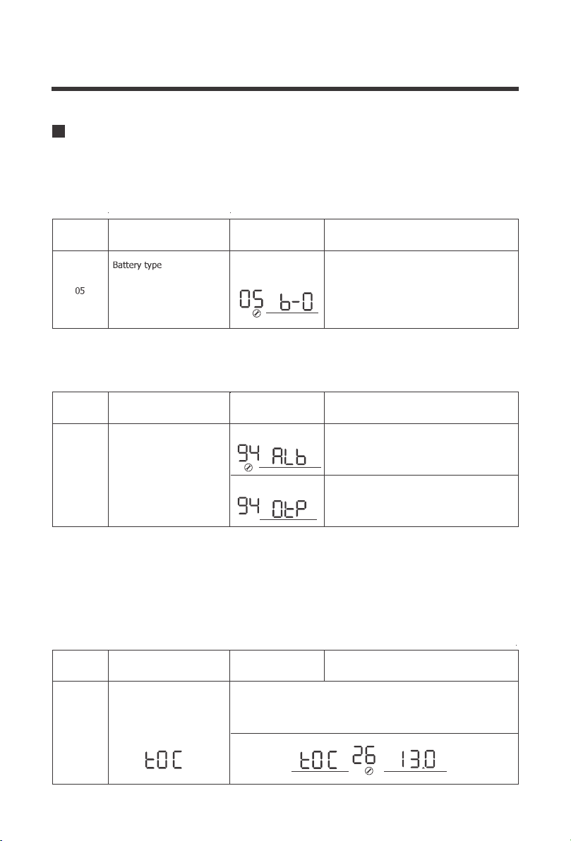
05 Custom Battery Type /User Mode
21
Maximum charging voltage
for Lithium battery. When
the voltage reaches the set
voltage, charging will stop.
V
BATT
If the preset battery options are not compatible with your system, you will need to custom the
charging by following the next steps.
2.Go to Program 94 to determine whether the custom battery is a Lithium or non-lithium
battery, Refer to the chart below:
1. Set the battery type to b-0. By default this unit is preset to boost at 14.3V and Float at
13.7V.
3.If choosing a custom lithium battery, make sure the previous Program 94 is at ALb.
Otherwise if programming a non-lithium battery skip to Step 4.
a.After setting Program 94, go to Program 26 to select the maximum charging voltage for your
custom lithium battery. Please Note when the voltage set point is reached, the custom lithium
battery will stop charging
User-defined
(
default fast V 14.3,
Floating V 13.7)
For Charging to be
accurate, Temperature
Sensor must be connected.
Program
Number
Parameter
Setting
Description
If User-Defined is selected ,user can set the
battery type in program94
If selected, battery charge voltage and
battery low open charging can be set up in
program 26,27
Program
Number
Parameter
Setting
Description
Other battery
Lithium battery
If selected ,battery charge voltage can be set
up in program 26,27
If User-defined is selected in program 94,this program can be set
the maximum charging voltage.Setting range is from 13.0V-15.5V
Selection of battery type
Program
Number
Parameter
Setting
Description
26
94
22
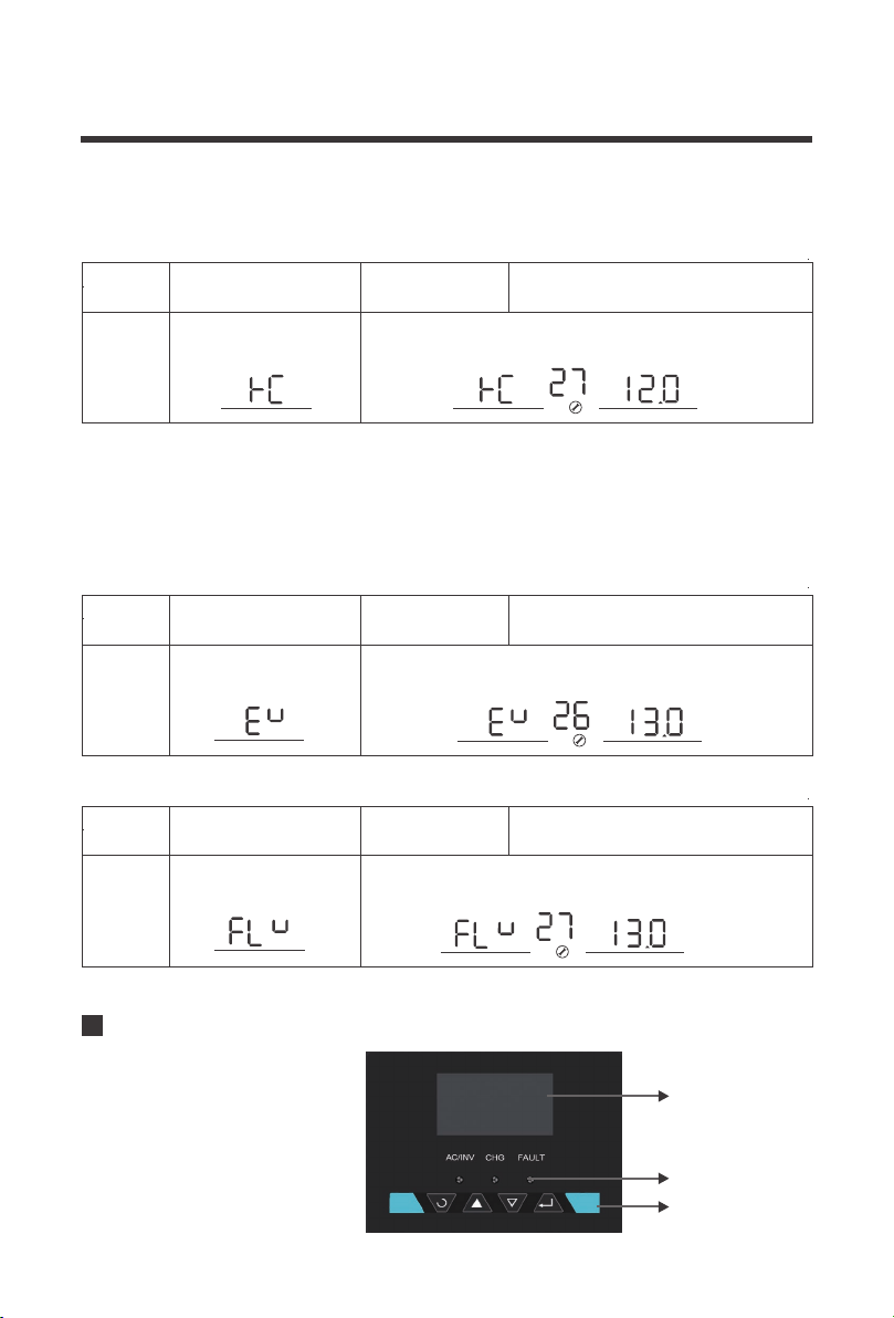
If User-defined is selected in program 94,this program can
be set up.Setting range is from 13.0V to 15.0V for 12V
Floating charging voltage
If User-defined is selected in program 94,this program can be set
up.Setting range is from 12.0V to 14.0V for 12V
Battery low voltage open
charging(for lithium battery)
V
BATT
V
BATT
V
BATT
b.Once finished, go to Program 27 to set the battery low voltage recovery charge. This will be
the voltage that the battery discharges to before the inverter-charger charges the battery to the
predetermined maximum charging voltage
a.After setting Program 94, go to Program 26 to select the boost charging voltage for your
custom non- lithium battery.
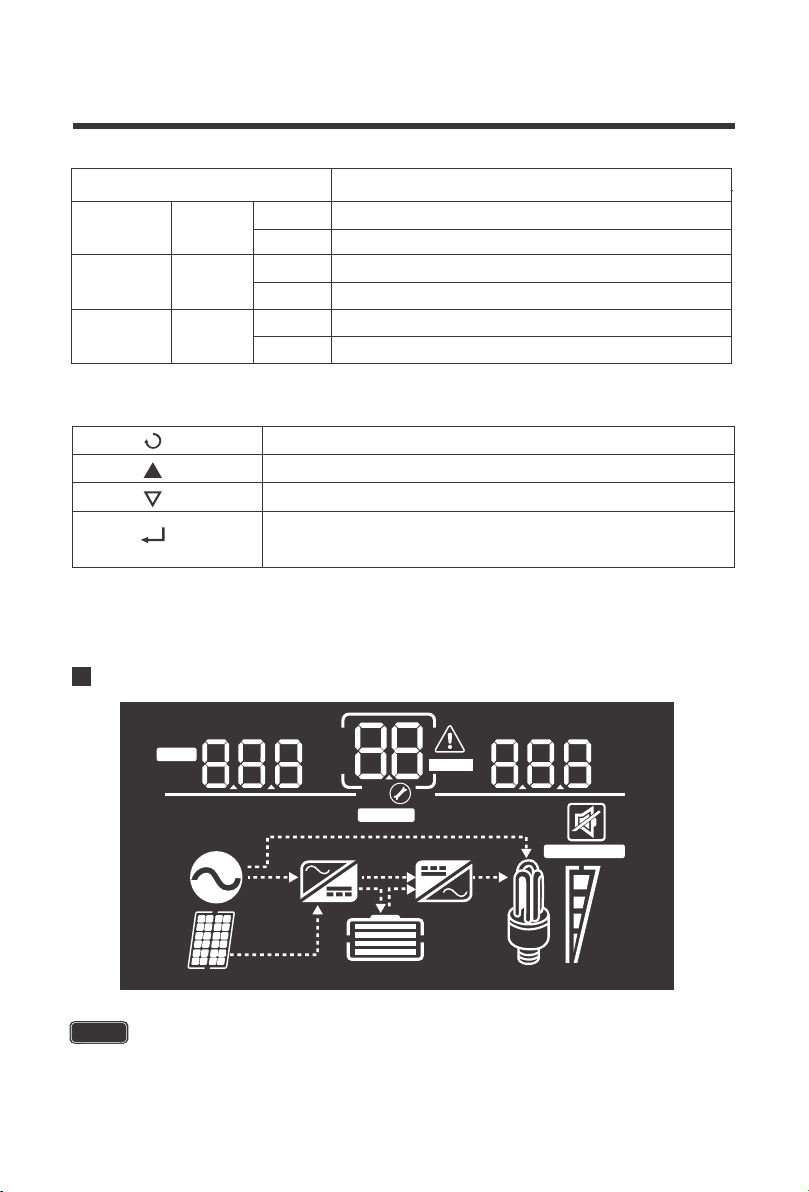
The operation and display
panel,shown in chart below.is on
the front panel of the inverter.It
includes three indicators,four
function keys and an LCD
display,indicating status and
input/output power information.
b.Once finished, go to Program 27 to set the battery float charge.
4.If choosing a custom non-lithium battery (i.e.. Deep cycle), make sure Program 94 is
set to 0tP
Program
Number
Parameter
Setting
Description
27
Program
Number
Parameter
Setting
Description
27
If User-defined is selected in program94,this program can be set
up.Setting range is from 13.0V to 15.0V
Bulk charging voltage(C.V
voltage)
Program
Number
Parameter
Setting
Description
26
Display Panel
LED display
LED indicators
function keys
23
100%
25%
VA
%
KW
Hz
OUTPUTBATTLOAD
ERROR
VA
%
C
KW
Hz
INPUTBATT
AC
BYPASS
OVER LOAD
CHARGING
LED Indicator Parameter
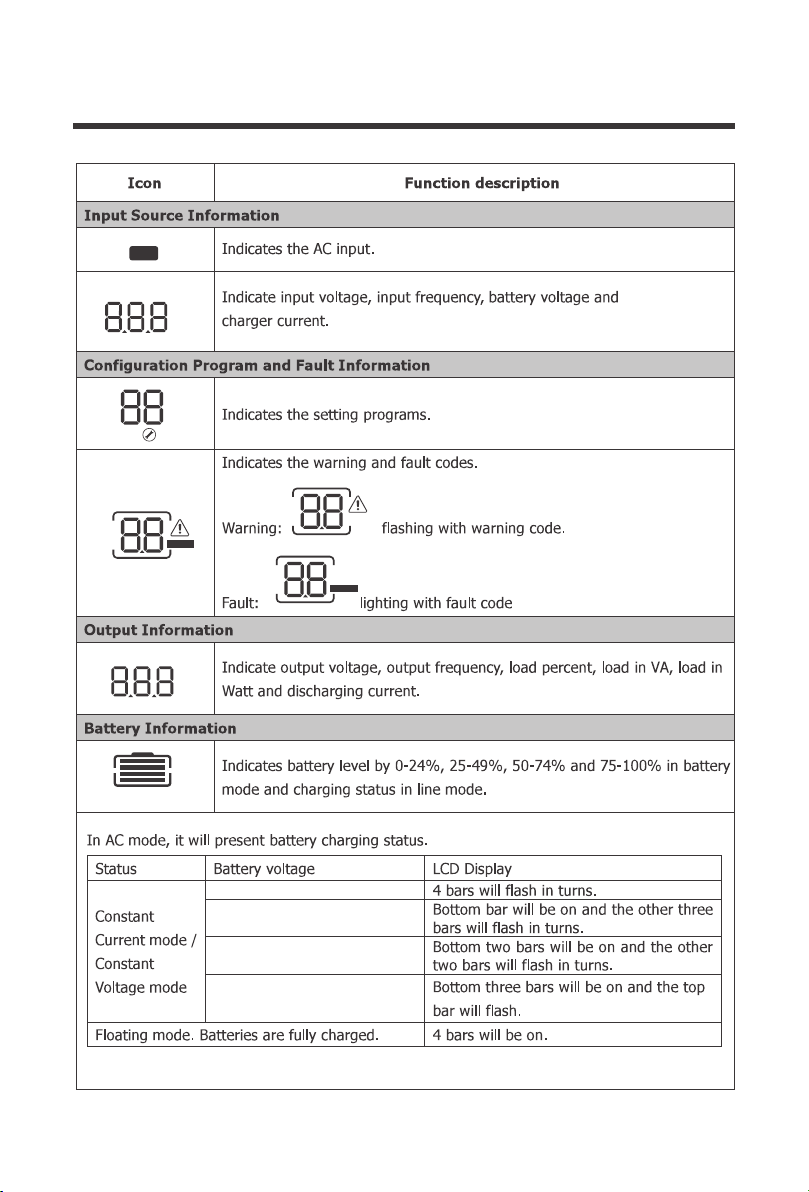
LCD Display Icons and Behaviors
AC/INV
CHG
FAULT
Green
Green
Red
Solid
Flashing
Output is powered by an AC source in line
Output is powered by battery or in invert mode
Solid
Flashing
Battery is fully charged
Battery is charging
Solid
Flashing
Fault occurred
Warning conditions has occurred
Exit setting mode, go back
1. Hold down to enter Parameter setting menu.
Cycle through the menu
Cycle through the menu
2. Press to confirm setting in parameter setting
Function Keys
some PCL inverter-chargers will differ in the LCD display on erroneous icons that do
not influence or modify the working mode of the inverter-charger.
NOTE
24
ERROR
ERROR
VA
%
C
KW
Hz
INPUTBATT
AC
<12.0V
>13.0V
12.0.V-12.5V
12.5V-13.0V
CHARGING
VA
%
KW
Hz
OUTPUTBATTLOAD
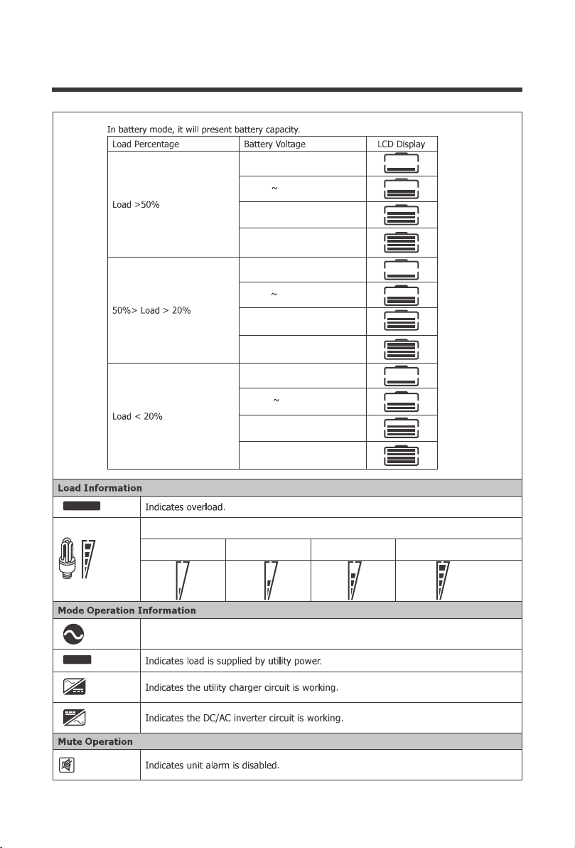
25
Indicates the load level by 0-24%, 25-49%, 50-74% and 75-100%.
0%-24% 25%-49% 50%-74% 75%-100%
<10.3V
>11.3V
<10.9V
>11.9V
<11.2V
>12.2V
11.7V~12.2V
10.9V
11.2V 11.7V
11.4V
10.8V~11.3V
10.9V~11.9V
10.3V 10.8V
Indicates unit is connected to shore power
OVER LOAD
BYPASS
100%
25%
Programmable Features
26
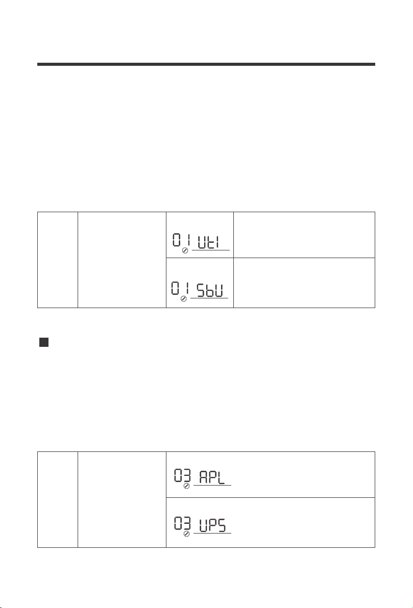
01 Utility Priority and Battery Priority
The PCL inverter charger series is fully programmable. You may change the respective
parameter by going to the Program Number listed below
Program
Setting Programs:
Description Selectable option
00
Exit setting mode, go back to main menu
1. Hold down to enter Parameter setting menu.
Cycle through the menu
Cycle through the menu
2. Tap to change/confirm setting in parameter setting menu
Function Keys
When setting Frequency, Output Voltage, The Charge Current, and AC input voltage
range, you must shut down the inverter charger completely for the changes to take effect
NOTE
Utility Priority
Battery Priority
The default setting is Utility Priority (Ut1). Under this setting, once the inverter charger is
connected to the utility, it will power the loads using the electricity from shore supply.
The inverter charger will start charging the battery bank using the AC source, if necessary.
In case of power outage, the system automatically switches to battery-powered mode.
The second setting is Battery Priority (SbU). Under this setting the inverter charger will
provide power using the connected battery bank even when it detects an AC source.
When the battery voltage reaches the low voltage set-point in Program 12, the inverter
charger will power the loads using the connected AC source but will not charge the battery
bank.
27
01
The following steps need to be taken to properly set the inverter charger to Battery Priority (SbU)
1. Press and hold the Enter key to enter the setting screen.
2. Press the down arrow key until setting 01 is shown.
4. Disconnect the inverter charger from the AC source/shore power.
5. Turn off the inverter charger, wait 10 seconds then turn it back on.
Press and hold the Enter key until the setting starts flashing, press the up or down arrow
key to select SbU. Press and hold the Enter key to save the setting.
By default, the PCL inverters are set to a narrow input voltage range for which the inverter
charger will work in Utility mode and then switch to backup mode. It is recommended to keep in
this mode if connecting sensitive electronic appliances like computers, TVs etc. as narrow
mode reduces the switch over time from external power source to batteries backup.
Selecting a wide input voltage range is recommended when you need power and might be
running a generator as they tend to have wider tolerance for a disturbed waveform or are having
issues with the stability of the main utility line. This will have a wider range to prevent switching
to backup battery mode if utility power is within the wider range.
Taking these steps will set the inverter charger to Battery Priority (SbU)
Utility will provide power to the loads as first
priority. Battery will provide power to the
loads only when utility power is not
available.
Battery provides power to theloads as first
priority.Utility provides power to the loads
onlywhen battery voltage drops to
eitherlow-level warning voltage or thesetting
point in program 12.
Output source priority:To
configure load powersource
priority
Battery priority
Utility first (default)
03
Wide
Utility effective range:Nominal output
voltage: -23%to+15%
Narrow(default)
Utility effective rangeNominal output
voltage:-15%to+15%:
Input voltage range
3.
03 AC Input Voltage Range
28
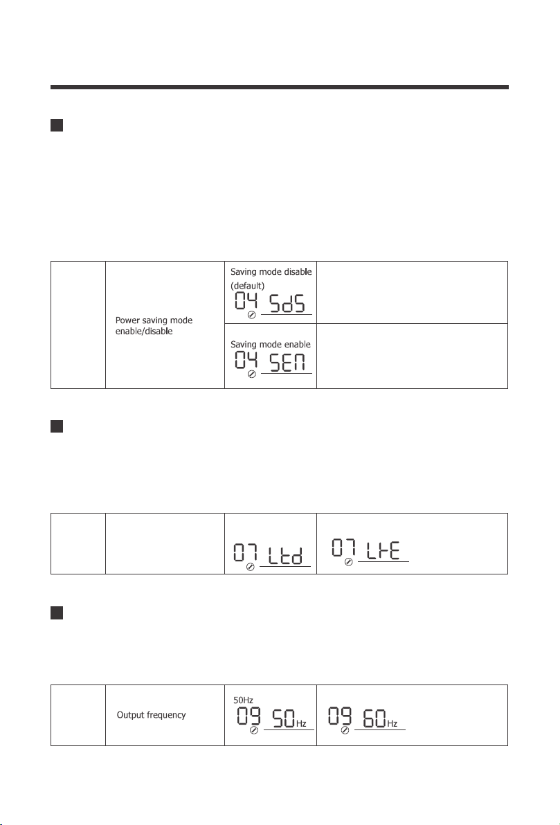
04
Power saver function is designed to conserve battery power when AC power is not or rarely
required by the loads. In this mode, the inverter pulses the AC output looking for an AC load
(i.e., electrical appliance). Whenever an AC load (greater than 50 watts) is turned on, the
inverter recognizes the need for power and automatically starts inverting and output goes to full
voltage. When there is no load (or less than 50 watts) detected, the inverter automatically goes
back into search mode to minimize energy consumption from the battery bank. In “Power saver
on” mode, the inverter will draw power mainly in sensing moments, thus the idle consumption
is significantly reduced.
04 Power Saving Mode
The operating temperature range for the PCL inverter charger series is 0C°-40C° / 32F° -
104F°. If internal power components begin to exceed their safe operating temperature level,
the inverter shuts down to protect itself from damage. This setting controls whether the inverter
charger automatically restarts after the unit cools down or whether the user has to manually
restart the unit.
07 Auto Restart Temperature Fault
If disabled, inverter output will be
available at all times.
If enabled, output of the inverter
will be off until a load greater than
50 watts is detected.
07
Restart disabled
(default)
Restart enabled
60Hz (default)
Auto restart when over
temperature occurs
The factory default frequency for inverters is 60Hz. Normally, manufacturers build electrical
devices for a certain amount of Current, Voltage and Hertz (Cycles) which is mentioned on the
name plate. The Current is dependent of the Voltage and the Hertz supplied to an electric motor
or appliance.
09 Output Frequency
09
29
The PCL inverter chargers can operate like battery chargers converting incoming AC power into
DC recharging power. The 2000W has a 65A max while the 3000W has a 75A max adjustable
battery charging.
11
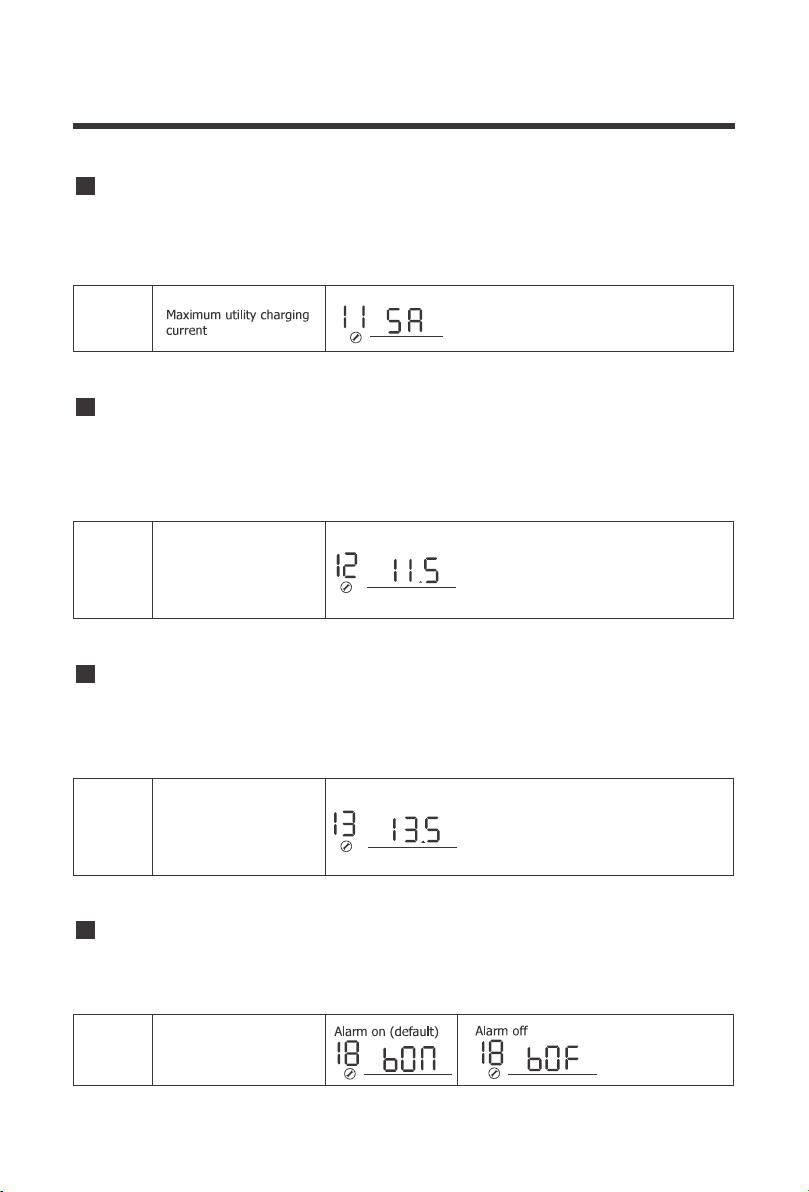
11 Maximum Utility Charging
The default is the maximum value (65A-2KW,
75A-3KW), with a 5A minimum.
The purpose of this setpoint is to protect the batteries from being over discharged. It assumes
that Battery Priority is set on Program 01. If utility power is not available, the designated setpoint
will cut of all working loads. Upon Utility power being detected, the Utility power/Generator will
then power the loads.
12
12 Low Battery Voltage Setpoint
The default is low battery voltage alarm set
point. The range is from 10.5V to 12.5V.if the
voltage set by user is below default point ,the
default is low battery voltage alarm point.
Increment of each click is 0.1V for 12V
Low battery voltage
inverter transfer to Utility
V
BATT
This setpoint indicates the recovery voltage to normal operation when a battery has been
over-charged or is over the voltage limit. The inverter charger will be in a fault state if the battery
voltage is above this designated setpoint and resume normal battery operation when reaching
this set point.
13
13 Over-Voltage Battery Recovery
Over-voltage battery
recovery
Over-voltage battery recovery can be set
between 13.0V to 15.5V. otherwise it is
output of bypass setting range is from
13.0Vto 15.5Vfor 12V,if the voltage set by
user Increment of each click is 0.1V for 12V
V
BATT
When the PCL inverter charger experiences a fault, the unit will automatically stop functioning
but have the option of having a fault alarm as well. Users may toggle this switch if they do not
want the alarm sound.
18
18 Alarm Control / Behavior
Beeps while function keys
are pressed
30
Alarm Parameters:
Pressing Function Keys
Working Mode Transfer
Overheating/Overload Alarm
Low-voltage/High-voltage Alarm
The buzzer will beep for 0.5s
The buzzer will keep beeping
The buzzer will beep for 0.5s
The buzzer will beep for 0.3s every 1s
The buzzer will beep for 0.2s every 0.5s
Inverter Charger Failure (Low-voltage
Shutdown, High-voltage Shutdown,
Overheating Protection, Overload Protection)
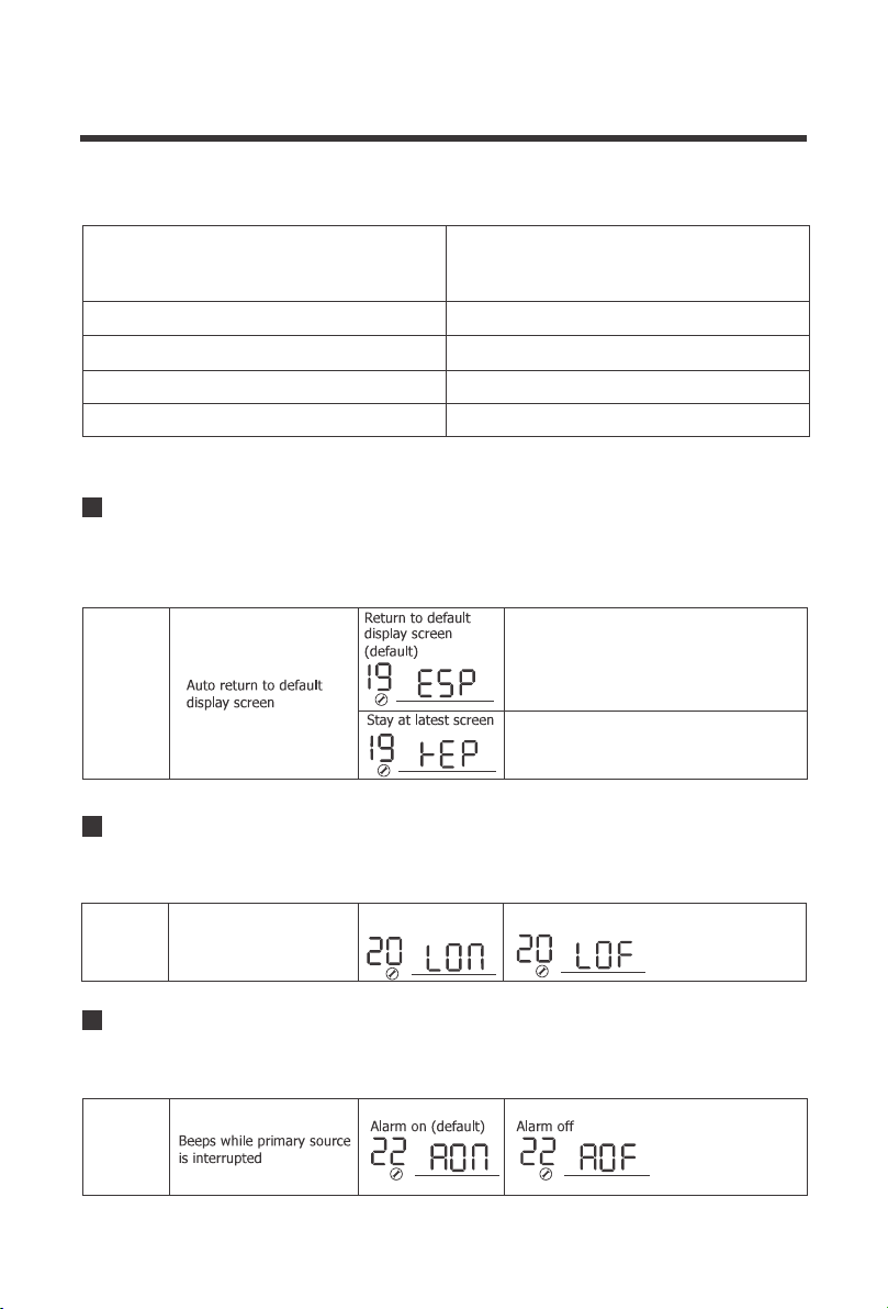
By default, the inverter charger will emit an audible noise when toggling any of the buttons. This
mode disables the sound for a quitter working mode.
22 Normal Mode Sound
22
The LCD display on the inverter chargers will stay on by default. Users may toggle this switch
to have the screen turn off after inactivity.
20 LCD Screen Mode
By default, after 1 minute of inactivity, the inverter charger will return to the first screen that is
seen when first powering on the unit. Users can change this mode to continue viewing the last
screen they left on before inactivity.
19 Screen Mode
19
20
LCD screen will turn of after inactivity.
LCD screen will stay
on indefinitely.(default)
LCD Screen Control
If selected display screen will
return to default screen (Input
voltage/ Output voltage) after 1
minute of inactivity.
Display screen will stay on current
screen until user changes it.
31
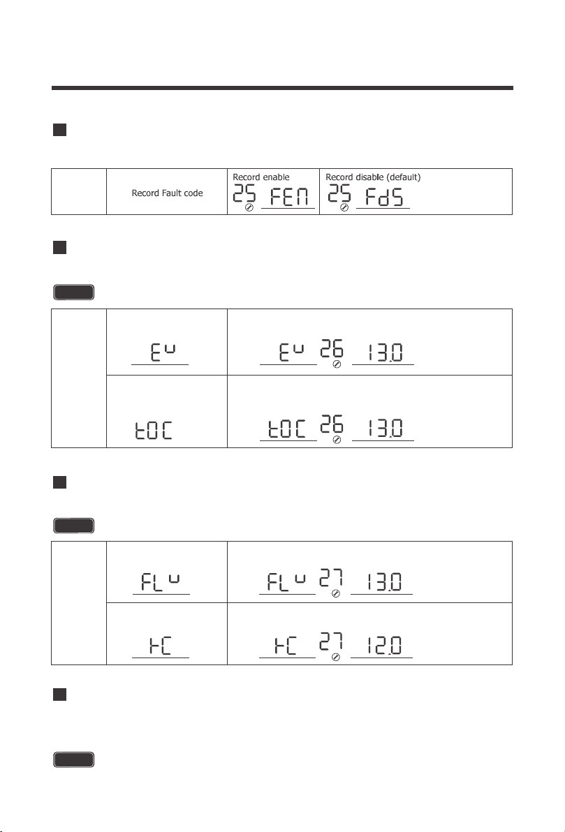
The PCL inverter will demonstrate the fault code.
25
25 Record Fault Code
Refer to Program 5 for modifying this setting.
26
26 Boost Charging
This program determines the cut-off voltage range for the PCL inverter charger battery input.
Upon reaching this voltage, the PCL inverter will cut off operation until the battery can go above
this voltage level.
This setting will not be modifiable if users choose a pre-set battery voltage.
NOTE
Bulk charging voltage(C.V
voltage)
If User-defined is selected in program 94,this program
can be set the maximum charging voltage. Setting
range is from 13.0V-15.5V
If User-defined is selected in program94,this program can
be set up. Setting range is from
program 94
Maximum charging voltage
for Lithium battery. When
the voltage reaches the set
voltage, charging will stop.
V
BATT
V
BATT
Refer to Program 5 for modifying this setting.
27
27 Float Charging
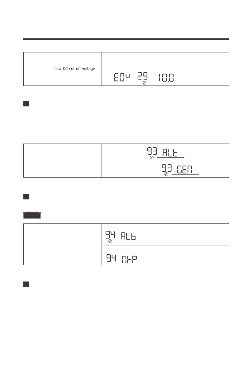
29 Low DC Cut-off Voltage
This setting will not be modifiable if users choose a pre-set battery voltage.
This value must be lower than Program 98: Low Battery Voltage Warning
NOTE
NOTE
If User-defined is selected in program 94,this program can
be set up.Setting range is from 13.0V to 15.0V for 12V
Floating charging voltage
If User-defined is selected in program 94,this program can
be set up.Setting range is from 12.0V to 14.0V for 12V
Battery low voltage open
charging(for lithium battery)
V
BATT
V
BATT
32
The PCL inverter charger series have functions to automatically start and stop a generator for
supplementing charge. The Auto Generator feature starts the Generator with the use of
Normally Closed (NC) contacts of the relay that “opens” when the battery voltage drops to the
programmed value of Program 96, Low Battery Voltage Set-point. The Normally Open (NO)
relay “closes”, and the auto generator start commences the generator to start charging the
battery bank. When the battery is recharged and its voltage rises to the programmed value of
Program 95, High Battery Voltage Set-point The NC (closes) contacts and NO (open) contacts
of relay reset and the Generator will stop / shut down the Generator automatically. The PCL unit
will then transfer back to “Inverting Mode”.
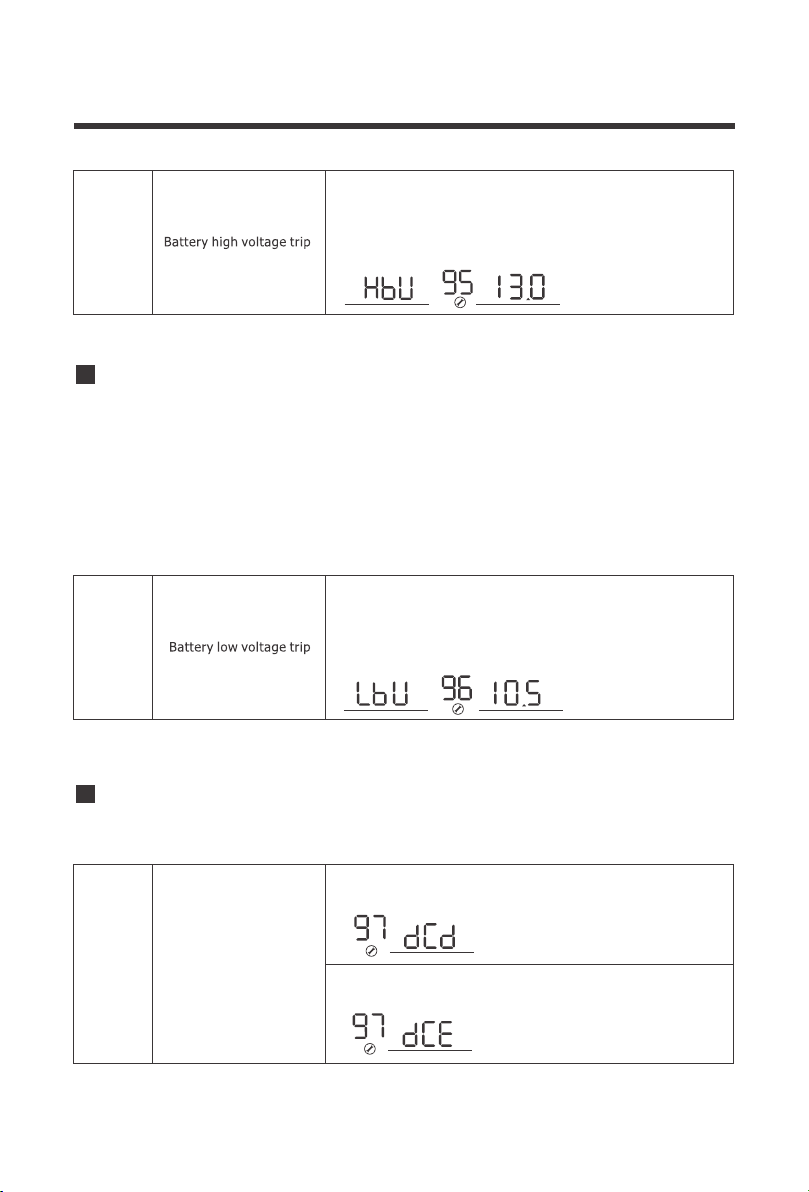
95 Battery High Voltage for Dry Contacts
Refer to Program 5 for modifying this setting.
94 Selection of Battery Type Custom
The factory default frequency for inverters is 60Hz. Normally, manufacturers build electrical
devices for a certain amount of Current, Voltage and Hertz (Cycles) which is mentioned on the
name plate. The Current is dependent of the Voltage and the Hertz supplied to an electric motor
or appliance. This program allows you to set the frequency range of the AC input source.
Special cases might require a wider frequency range than normal Utility and Generator outputs.
93 Input Frequency Range
93
This setting will not be modifiable if users choose a pre-set battery voltage.
NOTE
Special 40-70HZ
General 50HZ 45-55HZ
/ 60HZ 55-65HZ
Frequency Range
94
29
The default setting is 10.0V. Setting range is from 10.0V
to 12.0V with increments of 0.1V. This setting must be at
least 0.5V lower than setting #98 Low Battery Alarm.
V
BATT
Lithium battery
If selected, battery charge voltage
and battery low open charging
can be set up in program 26,27
Other battery
If selected ,battery charge voltage
can be set up in program 26,27
Selection of battery type
33
95
To modify battery set-points in Program 95 and Program 96, The dry contacts control needs to
be enabled. This allows control over the auto generator function.
The PCL inverter charger series have functions to automatically start and stop a generator for
supplementing charge. The Auto Generator feature starts the Generator with the use of
Normally Closed (NC) contacts of the relay that “opens” when the battery voltage drops to the
programmed value of Program 96, Low Battery Voltage Set-point. The Normally Open (NO)
relay “closes”, and the auto generator start commences the generator to start charging the
battery bank. When the battery is recharged and its voltage rises to the programmed value of
Program 95, High Battery Voltage Set-point The NC (closes) contacts and NO (open) contacts
of relay reset and the Generator will stop / shut down the Generator automatically. The PCL unit
will then transfer back to “Inverting Mode”.
96 Low Voltage Trip for Dry Contacts
97 Dry Contact Control
When dry contact switch from NC to NO, battery voltage
arrive to setting voltage, dry contact point switch to NC.
This setting can not be than fast charge voltage.higher
setting range is from 13.0V to 15.5V for 12V Increment of
each click is 0.1V for 12V
V
BATT
96
When battery voltage arrive to Setting point, the dry
contact switch from NC to NO. This setting can not be
lower than low battery voltage cut off point. setting
range is from 10.5V to 12.5Vfor 12V
Increment of each click is 0.1V for 12V
V
BATT
97
If inverter is set in dce, dry contact function enable
and 95,96 can be set up in program.
is
Dry contact control
If inverter is set in dcd, dry contact function is disable, ,96 can
not be set up in program.95
34
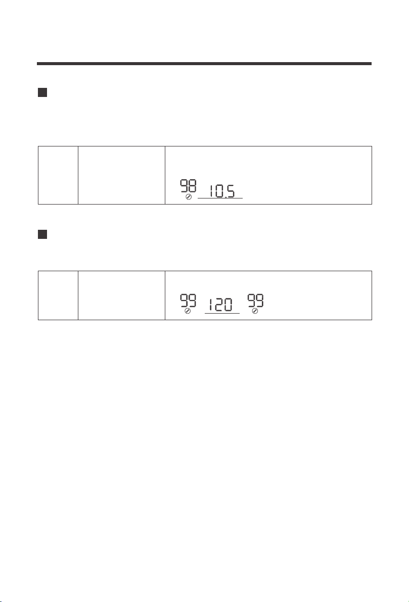
99 AC output Voltage
Users can select to have the PCL inverter-charger sound an alarm at a programmable battery
voltage. This will need to be a higher value than Program 29 Low DC Cut-off Voltage as it will
warn users that the battery is discharging before ultimately disconnecting.
Allows users to customize AC output voltages for devices that might need to meet a very
specific AC powering criteria.
98 Low Battery Voltage Alarm
98
99 AC output voltage
Low voltage battery alarm
The default is 10.5V. The setting range is 10.5V-12.5V
with increments of 0.1V. This setting will be at least
0.5V greater than setting #29
V
BATT
The default is 120V, can be set between 100V-120V
with increments of 5V
V
OUTPUT
35
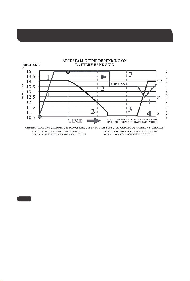
Battery Charging Stages
NOTE
Bulk Stage: The charger will supply constant current until the battery voltage reaches the
boost voltage. The software will calculate the time charging began up until the battery
voltage reaches 0.3V below the boost voltage. It uses this time to as T0 and T0×10 = T1.
Boost Stage: The charger will supply constant voltage and reduce the current slowly
through this stage. The charger will stay in this stage until T1 has run out. After this time the
charger will enter the float stage. This stage will last between 1 hour and 12 hours
depending on T1.
Float Stage: During this stage the charger will supply a constant voltage which is
determined by the battery selected and will keep current at a minimum. This stage acts as a
trickle charger.
Equalization: This stage is only available if the battery selector is switched to position 8.
During this stage the batteries are charged at a higher voltage than normal and for most
batteries this could cause damage. Please refer to the batteries owner’s manual or contact
the manufacturer to see if this stage is needed.
the stage period is determined by internal software
36
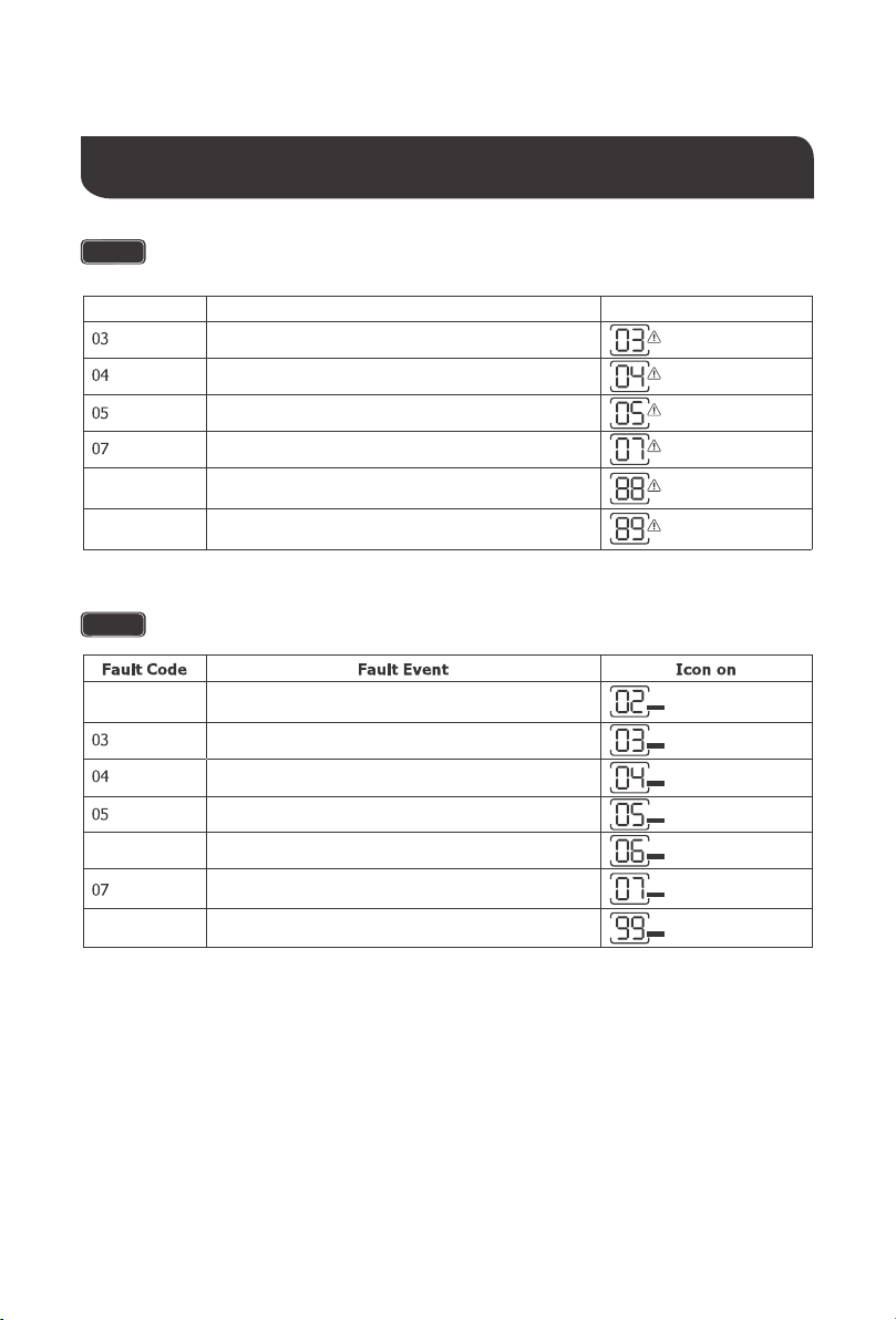
Fault / Warning Codes
NOTE
The following fault codes will have a caution symbol when experiencing the fault
NOTE
The following will experience an error display as well as the fault code
Inverter over temperature
88
89
Transformer phase reversal
Frequency is out of range
Battery voltage is too high
Battery voltage is too low
Output short circuit
Output is too high or too low
99
Inverter fail to slow start
06
Heat sink over temperature
Overload
02
Warning Code Warning Event Icon On
ERROR
ERROR
ERROR
ERROR
ERROR
ERROR
ERROR
Battery over voltage
Battery low voltage
Inverter overload
37
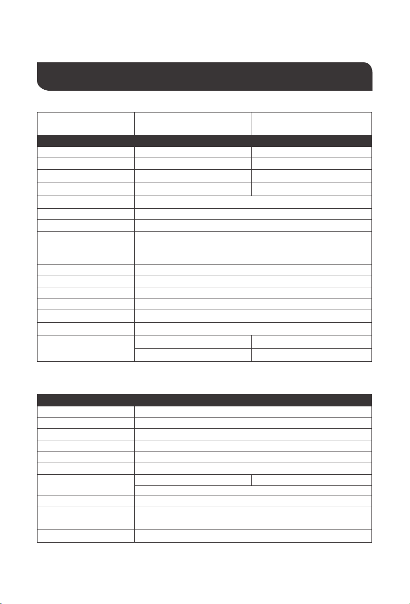
Technical Specifications
Model
Rated Output Power 2000W 3000W
Nominal output Voltage RMS
120 VAC ( 100 ~ 120VAC, 5V intervals
Outuput Frequency
50HZ ± 0.3HZ or 60HZ ± 0.3HZ
Output Wave Form
Pure Sine Wave
Output Overload
105% < Load < 120% ± 10% : Fault ( Turn off output after 10 seconds)
120% < Load < 150% ± 10% : Fault ( Turn off output after 3 seconds)
150% < Load ± 10% : Fault ( Turn off output after 1 seconds)
Nominal Input Voltage
12 VDC
Input Voltage Range
10~ 16 VDC ± 0.3 VDC
Low DC Warning Voltage
10.5 VDC ± 0.3 VDC
Low DC Cut-off Voltage
10 VDC ± 0.3 VDC
Short Circuit Protection
No load power Consumption
Software Protection
Nominal Efficiency
> 90% Peak
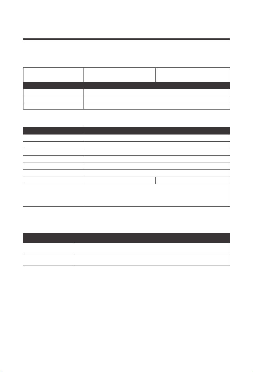
Nominal Input Voltage
120 VAC
Input Voltage Range
90-138 VAC
Input Frequency Range
40Hz - 70Hz
Input Wave Form
Sine Wave ( Utility or Generator )
Power Factor
0.9 - 1
Optimal Efficiency
>85%
Output Current
5-65A 5-75A
Configu
rable, 5A intervals
Short Circuit Protection
Circuit Breaker
Output Overload
120% < Load < 150% ± 10% : Fault ( Turn off output after 60 seconds)
150% < Load ± 10% : Fault ( Turn off output after 1 second)
Over Charge Protection Shutdown
16.0V for 12VDC
Inverter Specifications
Normal:<20W Normal:<30W
Power Saving:<15W Power Saving:<15W
Surge Power (1 second) 6000W 9000W
3000W 4500W
2400W 3600W
Surge Power (3 seconds)
Surge Power (10 seconds)
R-INVT-PCL1-20111S R-INVT-PCL1-30111S
Charger Specifications
38
Transfer Switch Specifications
R-INVT-PCL1-20111S R-INVT-PCL1-30111S Model
Battery Types
GEL, AGM, SLA, FLD, CAL, LI, USER
Operating Temperature Range
Humidity
0% ~ 95%
Noise <50dB
Dimensions
Weight 51.1 lbs / 23.2 Kg 63.5 lbs / 28.8 Kg
Certifications
ETL listed to CSA Standard
C22.2 No. 107.1 and UL458 with marine supplement
FCC part 15 Class B
General Specifications
0~40°C/0~104°F
-30~70°C/-22~158°FStorage Temperature
*Product specifications are subject to change without further notice
510 x 285 x 193 mm / 20.1 x 11.2 x 7.6 in
List dimensions
Wire length
2.8 x 4.3 x 1.3 in / 70 x 110 x 31.8 mm
Approx 16.4ft
Wired remote control
Transfer Relay Rating
Line Mode Efficiency
Transfer Time ~ 10ms
> 95%
30A Maximum Bypass

Renogy reserves the right to change
the contents of this manual without notice.
RENOGY.COM
US
2775 E Philadelphia St, Ontario, CA 91761, USA
909-287-7111
www.renogy.com
support@renogy.com
https://www.renogy.cn
support@renogy.cn
CN
400-6636-695
苏州高新区科技城培源路1号5号楼-4
CA
https://ca.renogy.com
supportca@renogy.com
https://au.renogy.com
supportau@renogy.com
AU
JP
https://www.renogy.jp
supportjp@renogy.com
https://uk.renogy.com
supportuk@renogy.com
UK
https://de.renogy.com
supportde@renogy.com
DE