Documents: Go to download!
User Manual
- User Manual - (English)
- Specification - (English)
- Warranty - (English)
- Product Overview
- Dimensions
- Operation
- LCD Programmable Features
- Electronic Protections
- Fault Codes
- Maintenance
Table of contents
User manual Solar Inverter Charger
Product Overview
Identification of Parts
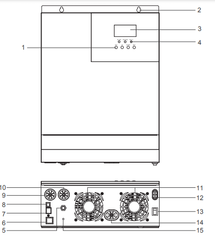
Key Parts
- LCD Buttons
- Mounting Holes
- LCD Screen
- LED Indicators
- AC Input Breaker
- Dry Contact Port
- RS485/CAN Communication Port
- USB Debugging Port (Internal Use)
- AC Input Terminal
- AC Output Terminal
- Cooling Fans
- PV Input Terminal
- Main On/Off Power Switch
- Battery Input Terminal
- Grounding Lug
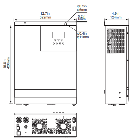
Dimensions
Optional Components

Renogy BT-2 Bluetooth Module:
The BT-2 Bluetooth module is a great addition to any Renogy charge controllers with a RS485 port and is used to pair charge controllers with the Renogy BT App. After pairing is done you can monitor your system and change parameters directly from you cell phone or tablet. No more wondering how your system is performing, now you can see performance in real time without the need of checking on the controller’s LCD.
Operation
Assuming all connections are correct and tightly secured, Locate the power button on the solar inverter and turn the main power switch to the ON position.
The following describes the basic operation of the solar inverter charger


LCD Operation
The solar inverter is equipped with 3 LCD indicators and 4 working buttons
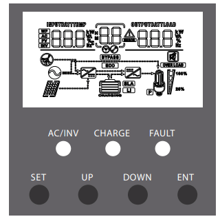
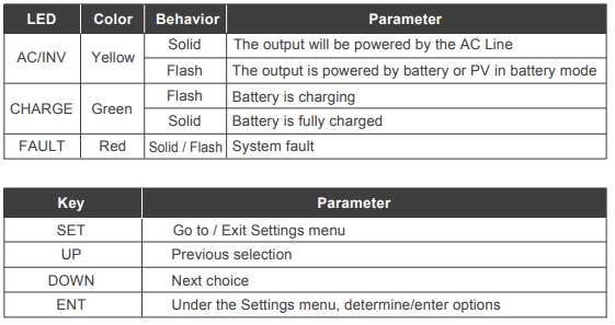

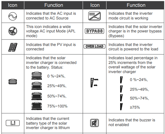
- The arrow only displays during startup and not part of the solar inverter functionality.
- Indicates that the utility/grid is powering the load.
- Indicates that the power utility/grid is powering the battery charging circuit (AC-DC)
- Indicates solar (PV) power to the battery charging circuit (DC-DC)
- Indicates that the charging circuit 1 is charging the battery.
- The arrow only displays during startup and not part of the solar inverter functionality.
- Indicates that the battery is powering the inverter circuit (DC-AC)
- Indicates that the inverter circuit is powering the load.

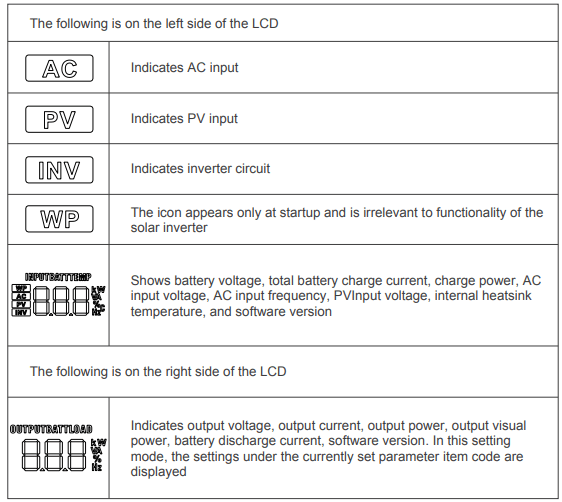
LCD Menu Screens
On the LCD home screen, press the "UP"and"DOWN" buttons to turn the page to view the solar inverter’s real-time data.
1 | Battery Input Voltage | Fault code | Load Output Voltage |
2 | PV Temperature | PV Output Kilowatts | |
3 | PV Input Voltage | PV Output Current | |
4 | Battery Input Current | Battery Output Current | |
5 | Battery Input Kilowatts | Battery Output Kilowatts | |
6 | AC Input Frequency | AC Output Load Frequency | |
7 | AC Input Voltage | AC Output Load Current | |
8 | Internal Parameters | Load Output KVA | |
9 | Inverter Temperature | Inverter Output Load Kilowatts | |
10 | APP Software Version | Bootloader Software Version | |
11 | Model PV Voltage Rating | Model PV Power Rating | |
12 | Model Battery Voltage Rating | Model Output Current Rating |
LCD Programmable Features
Press the "SET" key to enter parameter setting mode. After entering the settings menu, the parameter number 00 flashes and you can press the "UP" and "DOWN" keys to select the parameter code that you want to set. To access the parameter program press "ENT" key to enter the parameter editing state, at which point the value of the parameter flashes. Adjusts the value of the parameter through the "UP" and "DOWN" buttons, and finally press "ENT" to press the key, complete the edit of the parameter, and return to the parameter selection state.
Parameters Number | Parameter Name | Set options | Description |
| 00 | Exit | [00] ESC | Exit the settings menu |
| 01 | Load Working Mode | [01] SOL | Solar energy provides power to the loads as priority. If solar energy is not enough to power all connected loads, battery energy will supply power the loads at the same time. Utility provides power to the loads only when any one condition happens: - Solar energy is not available - Battery voltage drops to low-level set-point in Program 04 |
| [01] UtI (Default) | Utility will provide power to the loads as priority. Solar and battery energy will provide power to the loads only when utility power is not available. | ||
| [01] SBU | Solar energy provides power to the loads as priority. If solar energy is not enough to power all connected loads, battery energy will supply power to the loads at the same time. Utility provides power to the loads only when battery voltage drops to low-level set-point in Program 04. | ||
| 02 | Output Frequency | [02] 50.0 | The output frequency can be set through this menu. By default, the value should be 60Hz |
| [02] 60.0 (Default) | |||
| 03 | AC Input Voltage Range | [03] APL | By default, the input voltage range is the same, 90~140VAC |
| [03] UPS (Default) | By default, the input voltage range is the same, 90~140VAC | ||
| 04 | Battery Power to Utility Setpoint | 44.0V (Default) | Setting voltage point back to utility source when selecting “SBU ” or “SOL” in program 01. When the voltage of the battery is lower than this setting, the output switches from inverting to the utility. The setting range is from 39.6V - 52V, in 0.4V increments. |
| 05 | Utility to Battery Power setpoint | [05] 58.8V (Default) | Setting voltage point back to battery mode when selecting “SBU” or “SOL” in program 01. When the battery voltage is higher than the setting value, the output is switched from the utility to the battery mode. The setting range is 48V - 58.8V, in 0.4V increments. *Cannot be higher than [14] |
| 06 | Battery Charging Mode Please Note: If this inverter/charger is working in Battery mode or Power saving mode, only solar energy can charge battery. Solar energy will charge battery if it's available and enough | [06] CSo | Solar energy will charge battery as priority. Utility will charge battery only when solar energy is not available |
| [06] Cub | Utility will charge battery as priority. Solar energy will charge battery only when utility power is not available | ||
| [06] SnU (Default) | Solar energy and utility will charge battery at the same time. MPPT Solar energy will be priority charging and when it is insufficient, Utility will become priority. When the photovoltaic energy is sufficient again, Utility will stop charging | ||
| [06] oSo | Solar energy will be the only charging source even if utility is available | ||
| 07 | Maximum charging current: To configure total charging current for solar and utility chargers. (Max. charging current = utility charging current + solar charging current) | [07] 80A (Default) | The maximum solar charging is 80A, the maximum Grid/Utility charging is 40A (adjustable in Program 28), totaling the maximum current of 120A.The range can be configured between 0 ~ 120A |
| 08 | Battery type | [08] USE | User-defined, all battery parameters can be set |
| [08] SLd (Default) | Sealed lead-acid/AGM battery, constant voltage charging 58.4V, float charging voltage 55.2V | ||
| [08] FLd | Flooded lead-acid battery,constant voltage charging 58.4V,float charging voltage 55.2V | ||
| [08] GEL | Gel lead-acid battery, constant voltage charging 56.8V,float charging voltage 55.2V | ||
[08] LF14 LF15 LF16 | Lithium iron phosphate battery corresponding to 14 strings, 15 strings and 16 strings Default constant voltage charging voltage 14 strings: 50.4V 15 strings: 54V 16 strings: 57.6V | ||
[08] n14 n13 | Lithium-ion battery corresponding to 12 strings, 13 strings and 14 strings Default constant voltage charging voltage 13 strings: 53.2V 14 strings: 57.2V | ||
09 *available in USER and lithium setting only | Boost Charge Voltage | [09] 58.4 (Default) | Changes the charging voltage setting, set the range 48V to 58.4V, in 0.4V increments |
10 *available in USER setting only | Boost Charge Duration | [10] 120 min (Default) | Raise the boost charge time setting, refers to the constant voltage charging reached at Program 09 . The range is 5min to 900min, in 5 minute increments |
11 *available in USER setting only | Float Charge Voltage | [11] 55.2V (Default) | Floating charging voltage set range 48V to 58.4V, in 0.4V increments |
12 *available in USER and lithium setting only | Low Voltage Load Disconnect | [12] 42V (Default) | It is recommended to set this voltage below the maximum voltage the battery can withstand. When this voltage is reached, the loads will be powered off after a time delay adjustable in Program 13 The range is 38V to 50V, in 0.4V increments |
13 *available in USER and lithium setting only | Battery Over-discharged Delay Time **If a power shortage occurs and recovers in a short time, it can cause damage to your connected appliances. To prevent this kind of damage, please check manufacturer if heavy load appliances are equipped with time-delay function before installation | [13] 5S (Default) | The following parameter sets the delay-time after the battery voltage is below the set-point in Program 12. The set range is 5-50 seconds, in 5s increments |
14 *available in USER and lithium setting only | Battery Undervoltage Alarm | [14] 43.8V (Default) | Warning that the battery is approaching low voltage. The output does not shut down and the range is 40V to 52V, in 0.4V increments |
15 *available in USER and lithium setting only | Battery Discharge Limit Voltage | [15] 40V (Default) | When the battery voltage goes below this voltage set-point, the solar inverter will immediately disconnect and shut down immediately. The set range is 36V to 50V, in 0.4V increments |
16 *available in FLD and USER setting only | Set Equalization charging | [16] DIS | No equalization charging |
| [16] ENA (Default) | Enables equalization charging | ||
17 *available in FLD and USER setting only | Battery Equalization Voltage | [17] 59.2V (Default) | Set equalization charging voltage. The range is 48V to 59.2V, in 0.4V increments |
18 *available in FLD and USER setting only | Battery Equalization Duration | [18] 120min (Default) | Setting range is from 5min to 900 min. , in 5min increments |
19 *available in FLD and USER setting only | Battery Equalization Time-Delay | [19] 240min (Default) | Setting range is from 5min to 900 min, in 5min increments |
20 *available in FLD and USER setting only | Equalization interval | [20] 30 days (Default) | Setting range is from 0 days to 30 days, in 1 day increments |
21 *available in FLD and USER setting only | Enable Equalization Immediately | [21] DIS (Default) | Stops equalization charging immediately |
| [21] ENA | Starts Equalization charging immediately | ||
22 *Power-saving Mode (ECO Mode) | Power-saving Mode | [22] DIS (Default) | Disables power-saving mode |
| [22] ENA | After a 5min delay from setting, the inverter will enter a power saving mode and detect the load size. Loads greater than or equal to 50W, will be powered by the solar inverter. Otherwise, it will automatically stay in a low detecting mode and not power any loads under 50W | ||
| 23 | Overload auto-start | [23] DIS | Overload automatic restart is disabled, and the unit will not turn on the loads |
| [23] ENA (Default) | Enables automatic restart if the load shutdown output has occurred. The unit attempts to restart the output after 3 minutes and After 5 attempts the unit will not longer resume to turn on the loads | ||
| 24 | Overtemperature auto-start | [24] DIS | Over-temperature automatic re-start is disabled |
| [24] ENA (Default) | The over-temperature protection is activated and upon temperature dropping, the unit automatically restarts | ||
| 25 | Buzzer alarm | [25] DIS | No alarm |
| [25] ENA (Default) | Enable alarm | ||
| 26 | Alarm | [26] DIS | No alarm prompts when the status of the primary input source changes |
| [26] ENA (Default) | Enable alarm prompts when the status of the primary input source changes | ||
| 27 | Overload bypass: When enabled, the unit will transfer to line mode if overload occurs in battery mode. | [27] DIS | When disabled, the unit will not transfer to Utility mode |
| [27] ENA (Default) | When enabled, the unit will transfer to Utility mode if overload occurs in battery mode. | ||
| 28 | Maximum AC Charging Current | [28] 40A (Default) | The range can be configured between 0-40A |
| 29 | Split Phase | [29] DIS (Default) | Supply for industrial frequency transformer (disabled) |
| [29] ENA | Supply for industrial frequency transformer (enabled) | ||
| 35 | Low Voltage Disconnect Recover | [35] 50.4V (Default) | Set point that recovers and reconnects the solar inverter from being disconnected in Low Voltage Disconnect. The range is from 44V -58.4V, in 0.4V increments. |
| 36 | PV Charging Current | [36] 80A (Default) | Adjustable PV current settings. The range is from 0 – 80A. |
| 37 | Battery Charging Boost Return Setpoint | [37] 52V (Default) | When the battery reached at floating status, it will need to be lower than this setpoint before it starts charging. The range is the ( Undervoltage Warning )~ ( Floating Voltage – 1.2V )for the respective battery |
Electronic Protections
Number | Protection | Description |
| 1 | PV Current/Power Limiting Protection | When the configured PV array charge current exceeds the PV rated current, it will be charged at the rated current |
| 2 | PV Night anti-charge protection | At night, the battery is prevented from discharging through the PV component because the voltage of the battery is greater than the voltage of the PV component |
| 3 | Overvoltage Protection | Triggered when AC Input voltage reaches 140V |
| 4 | Power Input Undervoltage Protection | When utility input is below 90VAC, charging is stopped and the solar inverter is in inverter mode |
| 5 | Battery Over-voltage Protection | When the battery voltage reaches the overvoltage disconnect point, the PV and the utility automatically stop charging the battery, preventing damage from overcharging the battery |
| 6 | Battery low-voltage protection | When the battery voltage reaches the low voltage disconnect voltage point, the battery discharge is automatically stopped to prevent excessive discharge of the battery from being damaged |
| 7 | Load output short-circuit protection | When a short-circuit fault occurs at the load output, the output AC voltage is immediately turned off and outputs again after 1sec, for 3 more attempts. If they fail, then the unit will need to be manually powered on |
| 8 | Over-temperature protection | When the internal temperature of the unit is too high, the it will stop charging and discharging |
| 9 | Overload protection | Output again after 3 minutes after overload protection, overload 5 times in a row until the solar inverter charger is powered back, with A table of technical parameters after reference to the load level and duration of the manual |
| 10 | PV reverse polarity | Protection against reversing PV input connection |
| 11 | Bypass Protection protection | Prevents battery power mode from inverting when bypass is active |
| 12 | Bypass Flow Protection | Built-in AC input overcurrent protection circuit breaker |
| 13 | Battery input overcurrent protection | When the battery discharge output current is greater than the maximum and lasts 1 minute, the AC input is loaded |
| 14 | Battery input protection | When the battery is reversed or the inverter is shorted inside, the internal battery input fuse of the inverter fuses to prevent battery damage or fire |
| 15 | Charge short-circuit protection | The inverter protects and stops when the external battery port is shorted while the PV or AC is charging stop the output current |
Fault Codes
Fault code | Fault name | Description |
| 【01】 | BatVoltLow | Battery under-voltage alert |
| 【02】 | BatOverCurrSw | Battery discharge current software protection |
| 【03】 | BatOpen | Battery not detected |
| 【04】 | BatLowEod | Battery undervoltage stopdischarge alarm |
| 【05】 | BatOverCurrHw | Battery overcurrent hardware protection |
| 【06】 | BatOverVolt | Charge overvoltage protection |
| 【07】 | BusOverVoltHw | Bus overvoltage hardware protection |
| 【08】 | BusOverVoltSw | Bus overvoltage software protection |
| 【09】 | PvVoltHigh | PV overvoltage protection |
| 【10】 | PvBuckOCSw | Buck Overcurrent Software Protection |
| 【11】 | PvBuckOCHw | Buck Overcurrent Hardware Protection |
| 【12】 | bLineLoss | utility power down |
| 【13】 | OverloadBypass | Side-by-side load protection |
| 【14】 | OverloadInverter | inverter overload protection |
| 【15】 | AcOverCurrHw | Inverted overcurrent hardware protection |
| 【16】 | - | - |
| 【17】 | InvShort | Inverter short-circuit protection |
| 【18】 | - | - |
| 【19】 | OverTemperMppt | Controller overtemperature protection |
| 【20】 | OverTemperInv | inverter over temperature protection |
| 【21】 | FanFail | Fan failure |
| 【22】 | EEPROM | Memory failure |
| 【23】 | ModelNumErr | Model settings are wrong |
| 【24】 | - | - |
| 【25】 | - | - |
| 【26】 | RlyShort | Error between AC output and bypass |
| 【27】 | - | - |
| 【28】 | - | - |
| 【29】 | BusVoltLow | Internal battery boost circuit failure |
Fault | Solutions |
| Screen not displaying | Make sure the battery is properly connected and charged to be able to recognize the solar inverter. or click any button on the screen to exit screen sleep mode. |
| Rechargeable battery overvoltage protection | Measure whether the battery voltage exceeds 60Vand disconnect the photovoltaic array from and the power-on. |
| Battery undervoltage protection | Wait until the battery is charged to return to above the low voltage recovery voltage. |
| Fan failure | Check that the fan is not turning or is blocked by something else. |
| Over-temperature Protection | When the temperature of the equipment cools to, normal charge and discharge control is restored. |
| Overload Protection | (1) Reduce the use of electrical equipment;(2) restart the solar inverter charger and load recovery output. |
| Inverter short-circuit protection | Disconnect or reduce any loads from the unit. Shut down the solar inverter charger and turn on again to clear the error. |
| PV overvoltage | Check with the meter if the PV input voltage is above the maximum allowable input voltage of 145 V operating voltage. |
| Battery missed alert | Check that the battery is not connected or that the battery side circuit breaker is not closed. |
Maintenance
In order to maintain optimal long-term performance, it is recommended to perform inspections of the following items twice a year.
- Make sure that the air flow around the solar inverter is not blocked and remove any dirt or debris from the radiator.
- Check all terminals to see if there is corrosion, insulation damage, high temperature or combustion / discoloration signs, tighten the terminal screws.
WARNING Danger of electric shock! Make sure that all power supplies on solar inverter disconnected and that all capacitive power is released before checking or operating accordingly!
See other models: RBM500-G1 200 WATT 12 VOLT KIT-STARTER400D RENOGY 200 WATTS 12 VOLTS MONOCRYSTALLIN KIT-RV400D
