Owners' Guide Tools- Home Improvement
Charge Controller Installation
The RENOGY Starter and RV Kits come with a PWM- type charge controller to optimally charge your batteries from solar power. Each charge controller comes with a separate detailed manual. It is recommended that you read the solar charge controller manual in detail. The instructions in this section are only a brief summary of the information contained in the manual. Make sure the solar panels and batteries are disconnected from the charge controller before mounting the charge controller.
Recommended tools to have before installation:

WARNING: Connect battery terminal wires to the charge controller FIRST then connect the solar panel(s) to the charge controller. NEVER connect solar panel to charge controller before the battery.
CAUTION: Do not over-torque or over tighten the screw terminals. This could potentially break the piece that holds the wire to the charge controller.
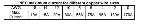
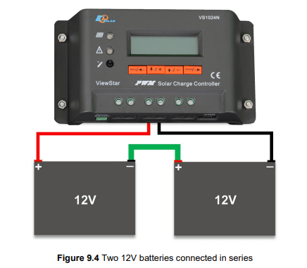
CAUTION: Refer to the technical specifications for max wire sizes on the controller and for the maximum amperage going through wires.
Mounting Recommendations:
WARNING: Never install the controller in a sealed enclosure with flooded batteries. Gas can accumulate and there is a risk of explosion.
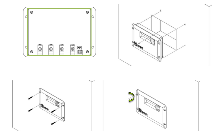
The Adventurer is designed for flush mounting on a wall. It consists of a face plate with projecting terminals on the backside for connecting the battery bank, panels, and optional sensors for accurate battery voltage sensing and battery temperature compensation. If utilizing the wall mount, then the wall will be required to be cut to accommodate the projecting terminals on the backside. Make sure that the pocket of the wall cut leaves enough space to not damage the terminals when the Adventurer is being pushed back into the cut out section of the wall.
The front of the Adventurer will serve as a heat sink, therefore it is important to ensure that the mounting location is not near any heat generating sources and ensure that there is proper airflow across the faceplate of the Adventurer to remove the heat dissipated from the surface.
- Choose Mounting Location—place the controller on a vertical surface protected from direct sunlight, high temperatures, and water. Make sure there is good ventilation.
- Check for Clearance—verify that there is sufficient room to run wires, as well as clearance above and below the controller for ventilation. The clearance should be at least 6 inches (150mm).
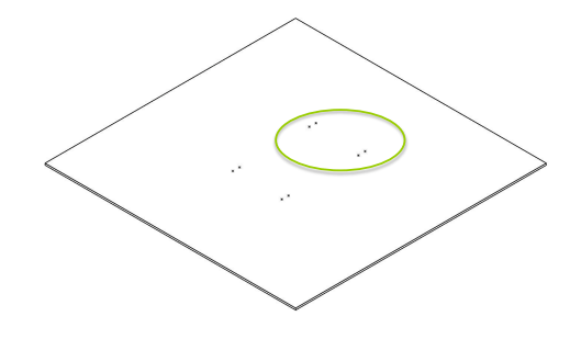
- Cut out Wall section—the recommended wall size to be cut should follow the inner protruding part of the charge controller while being careful not to go past the mounting holes. The depth should be at least 1.7 inches (43mm).
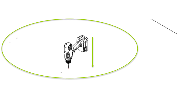
- Mark Holes
- Drill Holes
NOTE: The Adventurer comes equipped with screws for wall mounting. If they are not suitable try using Pan Head Phillips Screw 18-8 Stainless Steel M3.9 Size 25mm length screws.
- Secure the charge controller.
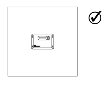
Wiring
- Unscrew battery terminals and connect battery connections
- Unscrew PV terminals and connect PV connections
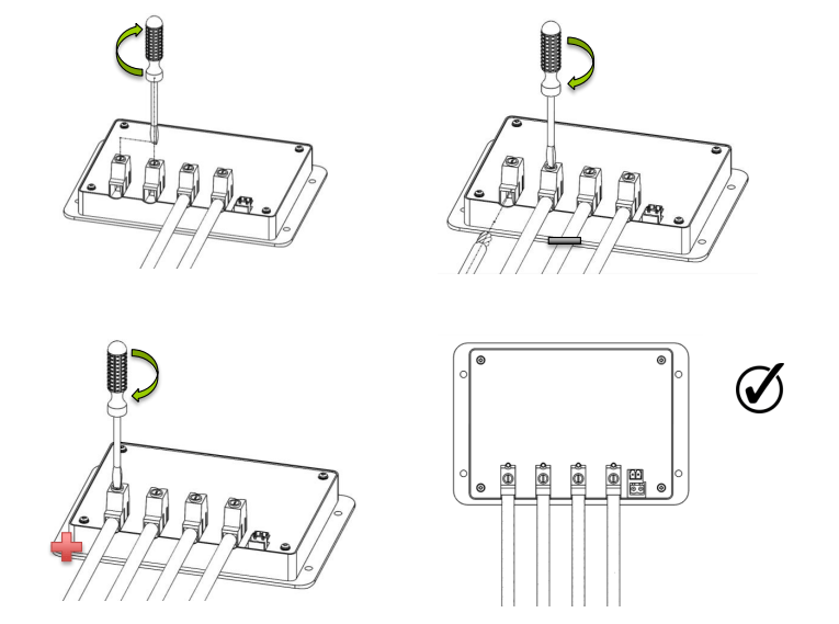
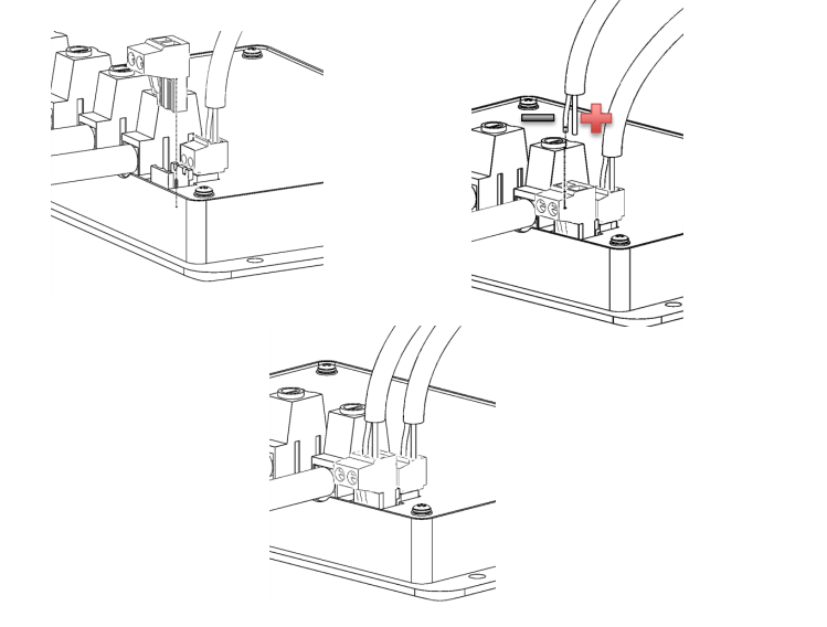
- Insert temperature sensor block terminal and connect wires (POLARITY SENSITIVITY DOES NOT MATTER)
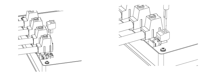
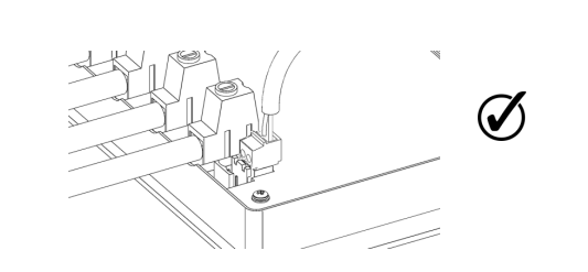
- Insert battery remote sensor block terminal and connect wires (POLARITY SENSITIVE)
Mounting Systems
In this section we are going to cover the basics for mounting 12V solar panels using the following:
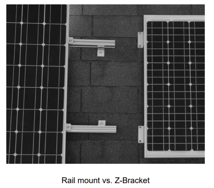
- RENOGY Z-Bracket Mount system
- RENOGY Rail Mount System
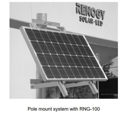
- RENOGY Single Pole Mount System
Z-Bracket Mounting
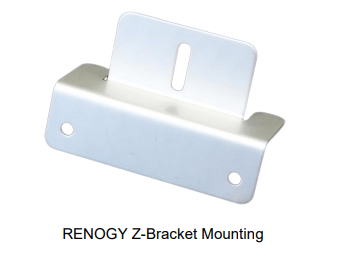
The Renogy Z-Bracket Mount System is designed to support the installation of single panel units, generally in off-grid installations. These units are ideal for installation on RV roofs and noninhabited dwellings such as sheds or garages. It is also suited as attachment to a user made structure such as a wooden frame. The system comes complete with all fasteners to secure the system to the installation surface. This system makes the installation of small solar systems easy, affordable and quick.
Key Features
- Lightweight
- Aluminum corrosion-free construction
- Ideal for RV’s and boats
- Ease of installation
- 1-year material warranty
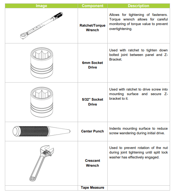
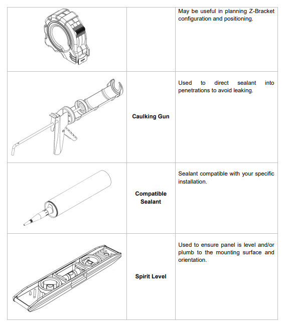
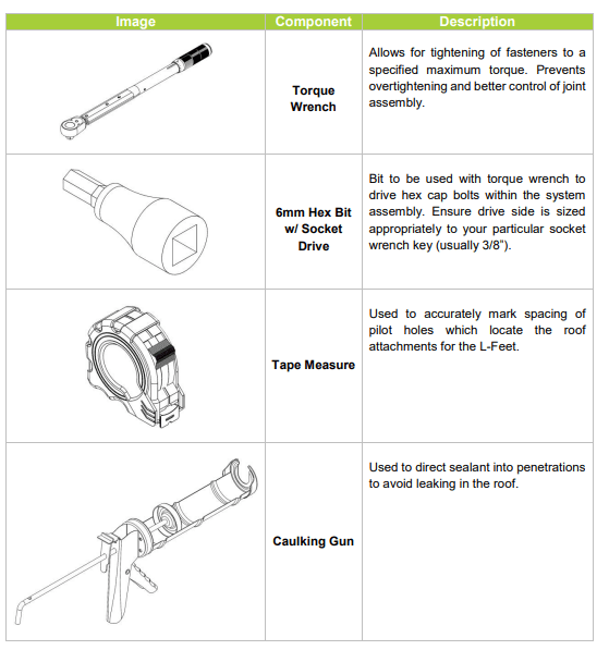
Recommended tools to have before installation:
The following tools and equipment are highly recommended to have available to assist with installation but are in no way a comprehensive list of tools that can ease installation. Installers feel free to substitute comparable equipment where appropriate.
WARNING: Installation on shingle roofs is not recommended. System is not designed with these roof types in mind. Fasteners will not penetrate framing deep enough and will likely cause heavy issues with leaking.
Making Brackets to panel Frame
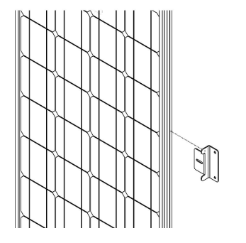
Repeat for each Z-Bracket in the set at each corner.
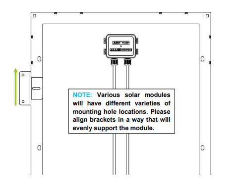
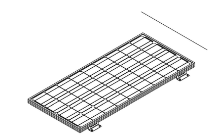
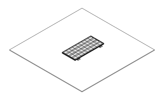
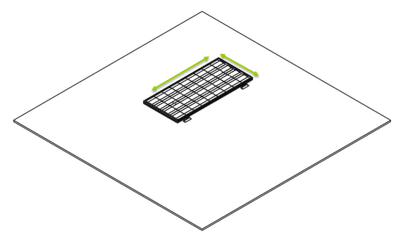
Install of Panel to General Mounting Surface
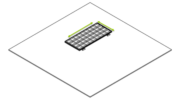

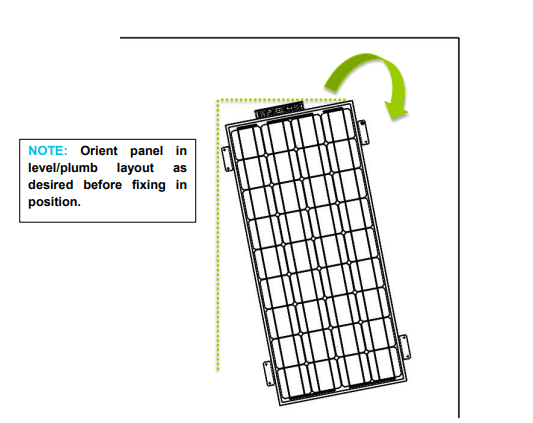
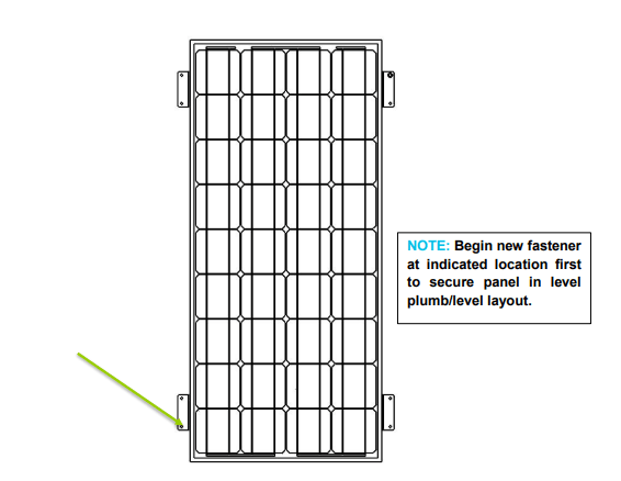
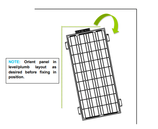
NOTE: Begin new fastener at indicated location first to secure panel in level plumb/level layout.
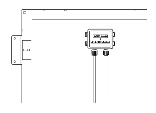
Repeat for all fastener locations.

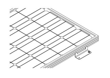
Repeat for all brackets.
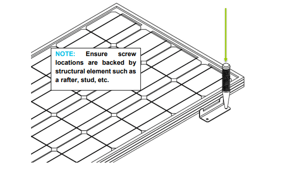
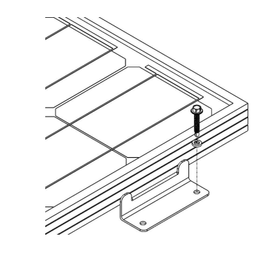
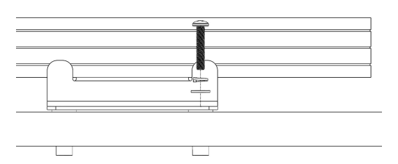
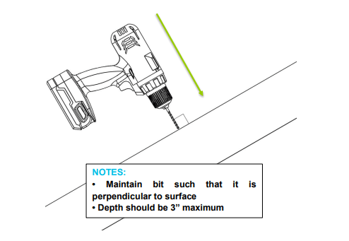
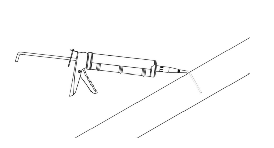
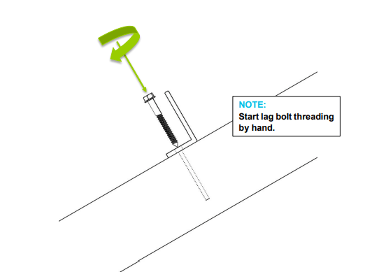
Install of Panel to RV Roofs
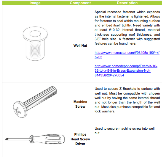
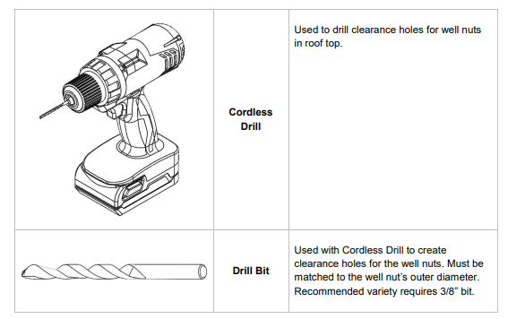
Installation on to the roofs of RV’s typically requires more specialized instruction due to the nature of construction of most commercially available RV roofs. Please note that this section includes the use of a fastener type NOT included in the Z-Bracket kit. This section is included for convenience of customers installing to an RV roof. The instructions listed in this section are a modification of the normal installation, all other steps are to be completed normally.
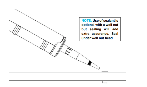
NOTE: A minimum roof thickness of 3/8” is recommended for this type of installation.
Additional components and tools required for this section:
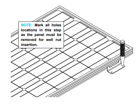
Repeat for all holes.
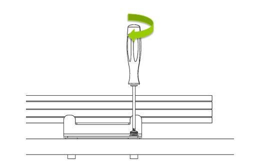
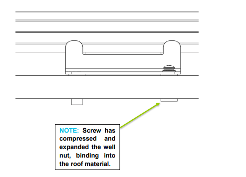
Repeat for all fasteners.
RENOGY Rail Mount System
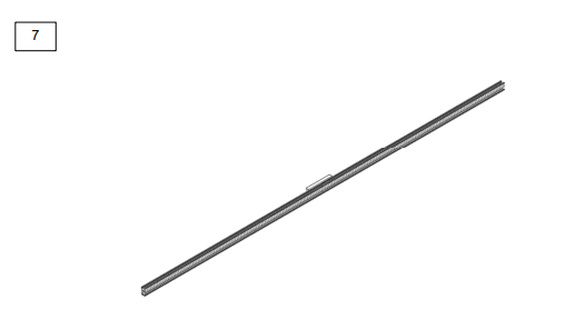
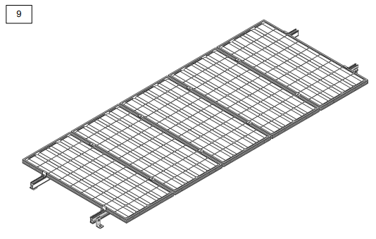
The Renogy Rail Mount System is designed to support off-grid and grid-tied solar photovoltaic systems and is compatible with all Renogy panel sizes, 100 W and larger. The system contains multiple components which will vary depending on a particular installation’s needs. A typical system will be comprised on the rail units themselves coupled with Splice Kits, L-Feet, End Clamps, and Mid Clamps as well as all required fasteners to secure all components together. This product makes the installation of long continuous rows of panels easy. This system is designed for use on flat rigid surfaces to ensure system stability.
Key Features
- Lightweight
- Supports multiple panel thicknesses
- Anodized Aluminum 6063-T5 Corrosion-Free Design
- Attractive mill finish, surface roughness B, C
- Snow loads up to 1.4 KN/m2 (0.20 psi)
- Wind speeds up to 60 m/s (134 mph)
- 1-year material warranty
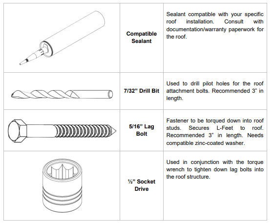
Recommended tools to have before installation:
The following tools and equipment are highly recommended to have available to assist with installation but are in no way a comprehensive list of tools that can ease installation. Installers feel free to substitute comparable equipment where appropriate.
WARNING: Installation of this system poses serious injury risks due to work on roofs. NEVER work alone during the installation of the system and ALWAYS use fall protection equipment. NEVER use any of the equipment attachment points as a support for fall protection.
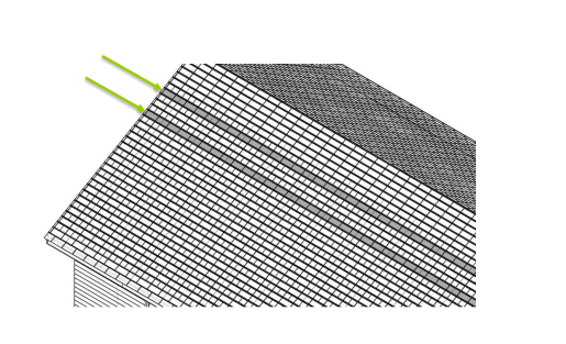
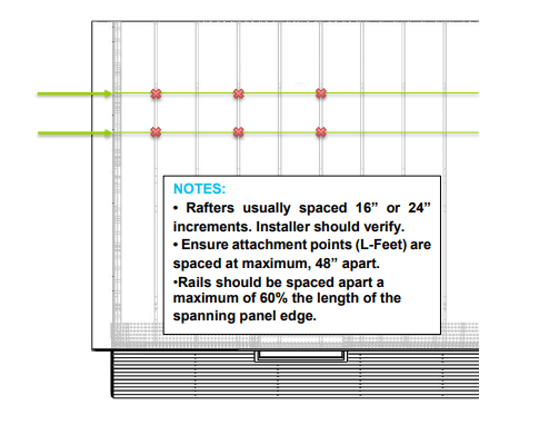
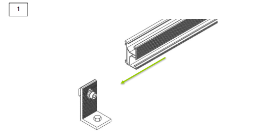
Roof Securements for Attachment Points
CAUTION: If using an alternative base for the L-Foot such as the MTS-QMSC or a third party standoff system to clear obstructions, please consult those product manuals for additional instruction before proceeding with this section.
NOTE: Leave L-Foot fasteners attached to the unit as they come packaged. This will ease attachment to the railing components later in the installation.
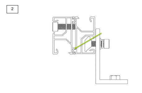
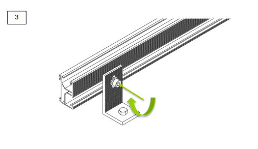
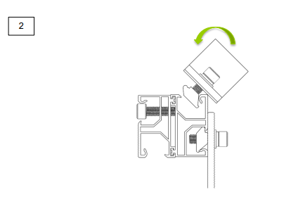
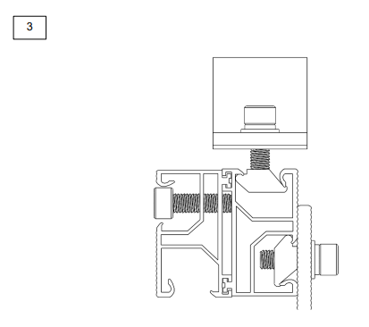
Rail System Construction

Repeat for all continuous rail sets.
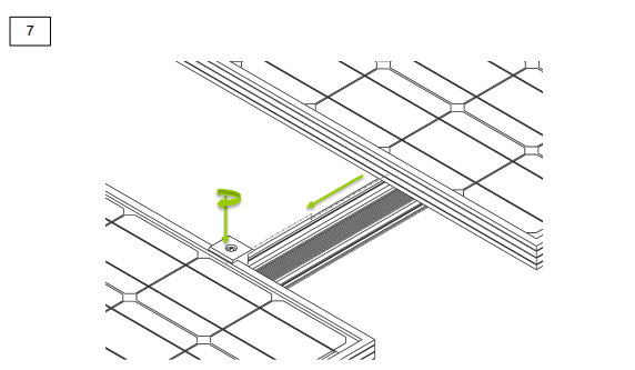
Rail Seating
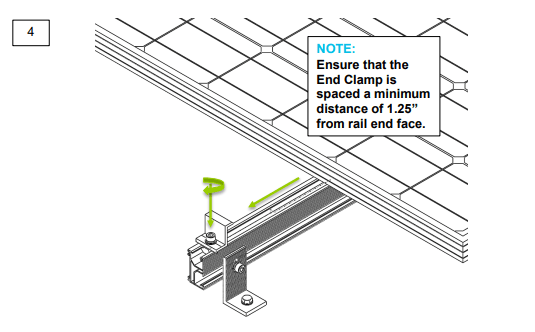
Panel Securement
WARNING: End clamps must be installed a minimum of 1” (30 mm) from the rail edges.
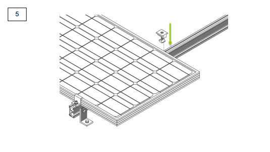
Continue mid-clamp procedure for each additional panel.
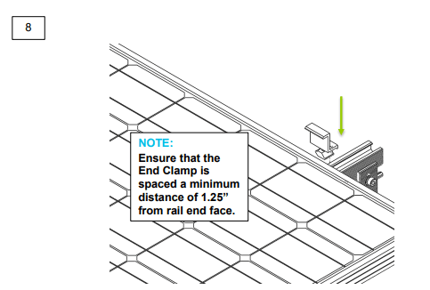
WARNING: End clamps must be installed a minimum of 1” (30 mm) from the rail edges.
RENOGY Pole Mount System
The Renogy Pole Mount System is designed for off-grid applications, when mounting to a roof is not ideal. It will support off-grid systems, and panels up to 100W. The system comes complete with all fasteners to secure the system to the installation surface. This system makes the installation of small solar systems easy, affordable and quick.
Key Features
- 5052-H32 aluminum construction
- Stainless steel fasteners
- High-tensile strength
- Corrosion Free
- Withstands 50 psf (125 mph wind loads)
- Attractive brushed aluminum finish
- Infinitely adjustable between 15-65 degrees
- Precision hole positioning and alignment
- Easy, rapid assembly
- Well-illustrated instructions
- Wind resistance of 120mph
- 1-year material warranty
Recommended tools to have before installation (Not Provided):
- Socket wrench
- Torque extension
- Box-Leveler
- Tape Measure
- 18mm wrench or socket for larger hex nut
- 13mm wrench or socket for smaller hex nut
The above tools and equipment are highly recommended to have available to assist with installation but are in no way a comprehensive list of tools that can ease installation. Installers feel free to substitute comparable equipment where appropriate.
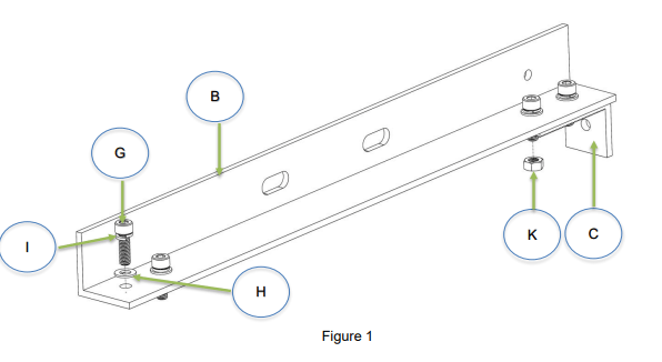
Note: All Cap Head Bolts (G) must have a Washer (H) and Spring Washer (I) prior feeding through a hole.
Fasten L-Channels to L-Brackets
A. Place Washer (H) flush to top surface of L-Channel (B), and align the holes.
B. Slide the Spring Washers (I)) onto the Cap Head Bolt’s (G) thread so that the bottom face of the Cap Head Bolt is touching the top surface of the spring washer.
C. Feed the thread of the Cap Head Bolt (G) through both L-Channel (C) and Washer’s hole. Repeat for all 4 holes.
D. Align the L-Bracket (C) with the bottom face of the L-Channel (B) and feed the protruding threads through the L-Bracket holes. Make sure the L-Bracket is flush and tighten bolts.
E. Fasten the L-Bracket (C) to L-Channel (B) with two small Nuts (K).
F. Repeat for both sets of L-Channel (B), fasteners, and L-Bracket (C).
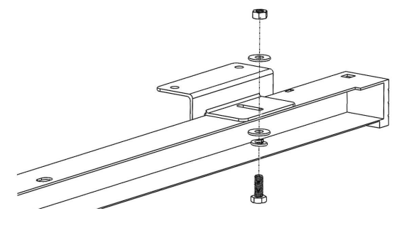
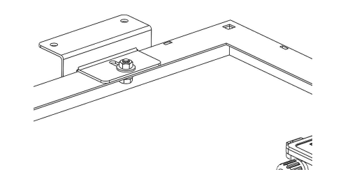
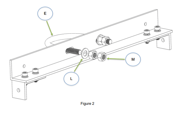
Slide U-Bolt through back face of L-Channel
A. Hold the assembled system up to pole so that L-Channel (B) back face is flush to surface of the pole and slide the U-Bolt (E) through the holes.
B. Fasten U-Bolt (E) with a large washer (L) and 1 or 2 nuts (M) (depending on how much thread is available.
C. Repeat for bottom L-Channel and last U-Bolt.
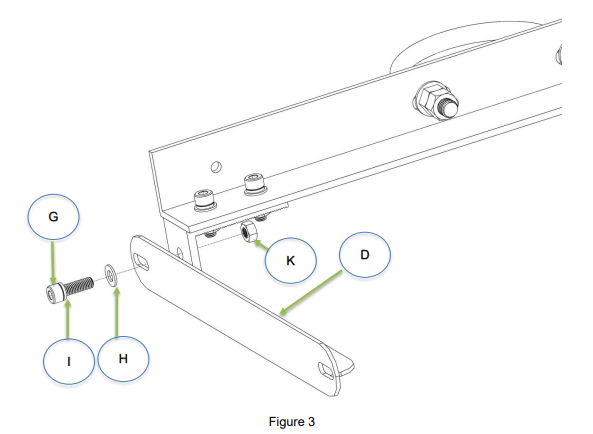
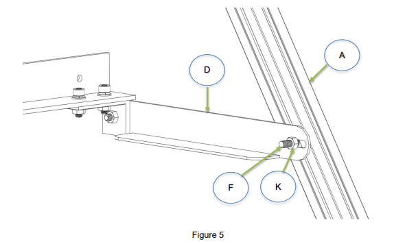
Attach Support Arm to bottom L-Brackets
A. Flush Support Arm (D) to L-Bracket (C) and align the holes.
B. Place washer on Support Arm (D) surface and align holes.
C. Feed a Cap Head Bolt (G) through Support Arm (D), and the L-Bracket (C).
D. Fasten it with small Nuts (K).
D. The orientation should be close to Figure 3.
E. Repeat for the other side.
Note: The reason for this is that depending on the angle that the T-Slotted brackets are fastened to the top L-Channel, you may need to adjust the bottom L-Channel so that it will be flush against the pole.
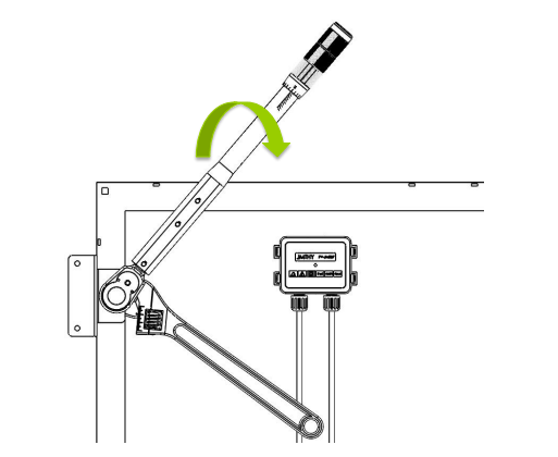
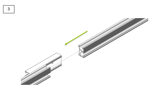
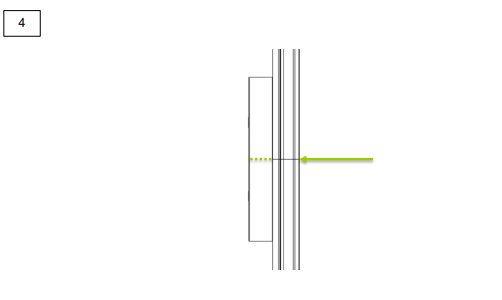
Fasten T-Slotted Brackets to top L-Channel using the L-Brackets
A. Slide T-Bolt (F) through the top of the T-Slotted Bracket (A) approximately 35mm (1.4in) down. There is no need to place a spring washer, or regular washer through the T-bolt.
B. Feed thread of the T-Bolt (F) through L-Bracket (C) and angle T-Slotted Bracket (A) as desired. The optimum angle will vary with your apparent position, relative to the sun. Range is usually from 60-75 degrees from the vertical.
C. Once desired angle has been achieved, fasten the T-Slotted Bracket (A) down with bolt. Be careful not to tighten too much, because it is possible to strip the T-Bolt.
D. Repeat process for both T-Slotted Brackets.
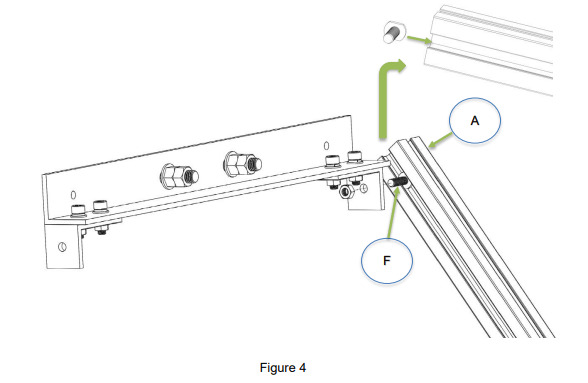
Note: It is important that the T-Slotted Brackets stay parallel. Nonparallel T-Slotted Brackets will cause the panel to bend which can cause micro-fractures in panel.
Fasten the bottom of the T-Slotted Brackets to Support Arm
A. Slide T-Bolt (F) through same slot as previous step. The distance that the bolt should slide depends on the angle that the T-Slotted Bracket (A) was fastened to the top L-Channel (B). Usually anywhere from 150mm to 250mm (6in to 9.8in) although it can exceed that if necessary.
B. The back planes of both L-Channels (B) should be parallel and flush to the pole. Achieving this may require reorienting the T-Slotted Bracket (A). It is recommended to fasten the Support Arms (D) to the T-Slotted Brackets temporarily until you can attempt to orient the assembly on the desired pole.
C. Once the assembly has been temporarily fastened, and is now near the pole, attempts can be made to attach the Pole Mount to the Pole.
D. If the backs of the L-Channels (B) are not flush to the pole surface, adjust the Support Arm (D) angle as needed until the desired angle is achieved.
E. Once desired angle has been achieved fasten the Support Arm (D) to T-Slotted Bracket (A) with a small Nut (K).
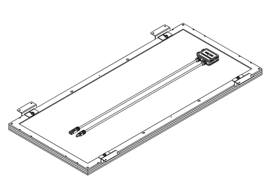
Slide panel onto brackets and fasten with end lamps
A. Hold the panel up to the pole mount to determine approximate position that End Clamps (J) must be to hold panel.
B. Start with the bottom clamps since they will hold most of the load.
C. Slide a T-Bolt (F) through T-Slotted Bracket (A) to the appropriate location.
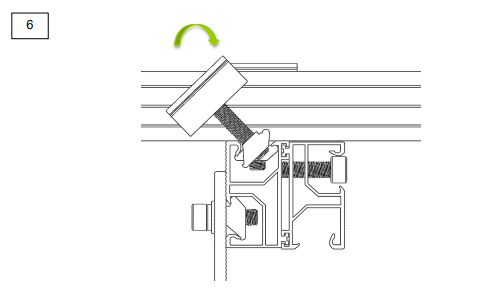
D. Orient the clamps as they are in Figure 6.
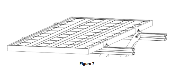
E. Once End Clamps (J) and in a position to hold the panel, slide the panel onto the bracket, slide the End Clamp over the edge of the panel so that the surfaces are flush as shown in Figure 7.
F. Fasten the End Clamp with a Nut (K) and Washer (H).
G. Repeat for the other bottom End Clamp, followed by the two top End Clamps.
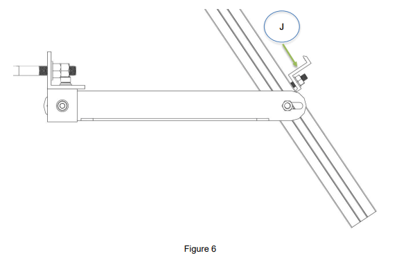
NOTE: This is what the clamp should look like when it is fastened to the panel. Also note that the thread length may not be as long as shown, but will still work.
12V wiring
In this section, we will show the basic 12V and 24V connections for off-grid systems that use a PWM- type controller. Please follow them thoroughly.
Caution!
The battery must first be wired to the charge controller before the solar panel is connected to the charge controller.
Battery to charge controller
The battery(s) must first be connected to the charge controller before proceeding to any other connections. Most PWM Controllers have automatic battery voltage detection, and the controller must detect what voltage level it will be charging at.
Before starting the connection, keep in mind the following:
- The charge controller should be as close as possible to the batteries. This helps keep line loss to a minimum level.
- Remember to always use the recommended gauge size based on the PV system and charge controller.
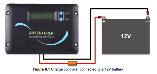
Refer to Figure 6.1 for connections.
- First, connect the negative cable to the negative (−) battery post. The best way to secure the battery cable to the battery post is by using a ring terminal. A bolt is sufficient to secure the ring terminal onto the battery post; doing so will allow for great electrical contact. Next, connect the bare stranded portion of the cable to the negative (−) battery input terminal on the charge controller.
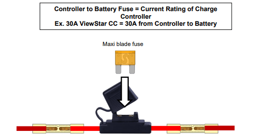
- Similarly to the instructions described above, connect the positive cable to the positive (+) battery post. For protection, an in-line fuse can be added to this cable. This is usually done with a fuse holder. If opting for an in-line fuse, please do the following before connecting the positive (+) cable to the charge controller:
- Make sure the fuse holder’s gauge wire size is matched.
- Attach the fuse holder to the line with a butt connector or by soldering it.
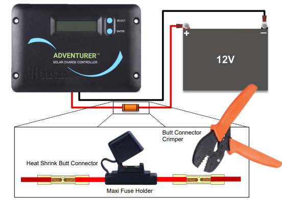
The butt connectors recommended for this application are the type with heat shrink insulation.
This will keep will give extra protection for the internal connection.
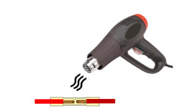
Use a crimper to splice the Maxi fuse holder with the battery cable. Once a strong connection is achieved, use a heat gun to shrink the insulation on the butt connectors.
- Once the fuse holder is in place, don’t attach a fuse just yet. Connect the bare stranded portion of the cable to the positive (+) battery terminal on the charge controller.
- The fuse between controller and battery should be the current rating of the controller. Once the fuse is properly sized, ensure that all connections were made properly, and that there are no loose connections present. Finally, insert the fuse into the fuse holder. The controller should power on.
- If opting for no in-line fuse, connect the bare stranded portion of the cable to the positive (+) battery input terminal on the charge controller directly from the positive (+) battery post, bypassing the fuse holder. The controller should power on.
Warning! Be careful not to short the battery. Reverse polarity connection will damage the charge controller and the resulting damage will not be covered by warranty.
Information about solar panels and PWM Controllers
When connecting a solar panel to the charge controller, please ensure that the correct type of panel or panel array is used.
Please note the following about PWM Controllers:
- 12V panels should be used with 12V battery systems only
- 24V panels or 12V panels configured in series to make 24V should be used with 24V battery systems only
- The solar array should not max out the rated power of the controller. Failure to obey this rule may result in the controller overheating or catching fire.
Extending the output wires of the solar panel
As we explained in the previous section, RENOGY Solar Panels are equipped with cables terminated by MC4 Connectors. To extend these cables, RENOGY provides adapter kits as shown in Figure 6.2.
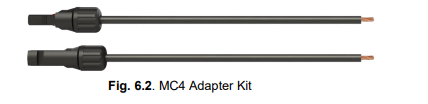
Adapter kits are sold in different lengths, and the basic gauge size is #12 AWG. Unassembled MC4 Connectors can also be purchased separately to make a custom adapter cable suitable for different length specifications.
Caution! The typical connection for 12V panels using a PWM Controller is a parallel connection. This connection increases the current, but keeps the voltage level the same. When placing multiple panels in parallel, it is necessary to size the wire gauge accordingly, and keep the distance between the solar array and the controller as close as possible.
Long runs of cable between the panel(s) and the controller increase the line loss if the gauges are not properly sized. We recommend keeping the distance between the solar array and the controller as close as possible.
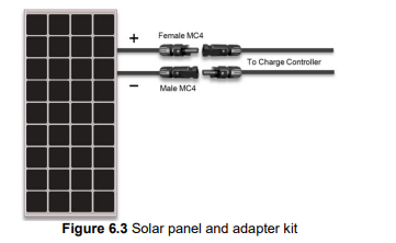
Please refer to Figure 6.3. This figure shows the extending of the output wires of the RNG-100D Solar Panel using the adapter kit. The polarity labeled on the panel’s leads should be the only ones to follow. When adapting the leads, mark the positive (+) cable; doing so will avoid reverse polarity when connecting the panel(s) to the controller.
Solar Panel to charge controller
Once the battery is connected to the charge controller and the panel(s) are positioned and mounted in the desired location, we are ready to connect the panel(s) to the charge controller. Panels should be mounted in a place that is free from shading by neighboring obstacles such as vents, air-conditioners, TV antennas, etc.
Hazard! The panel MUST be covered with a dark cloth to prevent the solar cells from producing energy; this will prevent and reduce shock hazard, which can be life threatening.
Please refer to Figure 6.4 when completing the following connections:
- First, mate the “Male” MC4 Connector from the solar panel that has the negative (−) label with the “Female” MC4 Connector of your adapter kit as shown in Figure 6.4. Then connect the bare stranded portion of the cable to the negative (−) solar input terminal on the charge controller.
- Next, mate the “Female” MC4 connector from the panel that has the positive (+) label with the “Male” MC4 connector of your adapter kit as show in Figure 6.4.
- The positive (+) solar cable can be fused for protection; an in-line fuse can be added to this cable in the same way as described in the instructions for battery to controller connection. Please refer to section 6.1 and follow the same procedure on how to add an in-line fuse.
- Once the fuse holder is in place, don’t attach a fuse just yet. Connect the bare stranded portion of the cable to the positive (+) solar terminal on the charge controller. Ensure that all connections are made properly, and that there are not any loose connections present. Finally, insert the fuse into the fuse holder and remove the protective cloth. If there is enough sunlight present, the controller will start charging the battery (ies).
- If opting for no in-line fuse, connect the bare stranded portion of the adapter cable to the positive (+) solar input terminal on the charge controller. Remove the protective cloth. If there is enough sunlight present, the controller’s solar LED indicator/icon on the LCD display should show that it is now charging your battery(s).
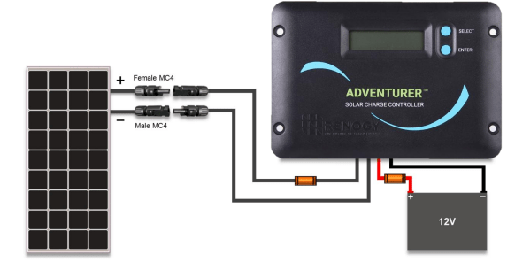
Figure 6.4 Completed 12V off-grid system
Figure 6.4 shows the complete wiring of a typical off-grid system. It includes fuses for safety and protection. This configuration shows only one panel and one battery connected to the controller. In Sections 8 and 9, more panel and battery configurations (respectively) will be described. Instructions will follow
24V wiring
General information
In this section we will show the basic connections for a 24V battery system. Please follow them thoroughly.
Caution! The batteries must first be wired to the charge controller before the solar panel is connected to the charge controller.
As we mentioned in last Section, the battery bank must first be connected to the charge controller before any other connections are made. This will allow the controller to set the 24V charging parameters automatically.
Before starting the connections keep in mind the following:
- The charge controller should be as close as possible to the batteries. This helps keeping line loss to a minimum level.
- Remember to always use the recommended gauge size based on the total input current. The PWM 30A LCD controller can handle gauges up to 6 AWG.
Please note the following about PWM controllers running in 24V configuration:
- 24V panels or 12V panels configured in series to make 24V should be used with 24V battery system only
- It is not recommended that you charge a 12V battery system with a 24V solar array. Doing so will result in a performance loss of 50%.
- The solar array should not max out the rated power of the controller. Failure to obey this rule may result in the controller overheating or catching fire.
Overall system connections
Please refer to Figure 7.1 for the overall wiring diagram for a 24V system.

Figure 7.1 Completed 24V off-grid system
As you can see from Figure 7.1, the batteries are configured in 24V by placing two identical 12V batteries in series. Likewise, the solar array is configured in 24V by placing two identical 12V panels (e.g. RNG-100D) in series.
The connections for a 24V off-grid system are very similar to those of a 12V connection. The process should be followed in the same way as outlined in Sections 6.1 to 6.4. The only difference is that the fuse selection changes, since a series connection increases the system Voc to ~45v. Therefore a fuse with a voltage rating of 50v or higher is recommended, since Maxi and ATO blade fuses have a maximum voltage rating of 32v.
With this being said, the same steps for a 12V system should be followed. Please read Sections 6.1 to 6.4.
Battery Configurations
The battery system can also be configured to create a “bank” of batteries. In this section, we cover the most basic configurations. When wiring batteries, extreme attention should be given. Never short a battery, as high currents can cause severe burns or even death.
Hazards! It is recommended that insulated/non-conducting tools be used when working with batteries. Never leave tools on top of the battery. Always wear eye protection. Never touch both of the battery terminals at the same time with your bare hands.
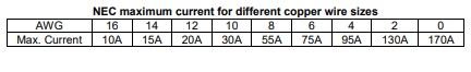
Series connection of batteries (12V)
When two or more batteries are connected in a series, their voltages add up, but the Amp-Hour (AH) capacity remains the same. Fig. 9.1 shows two 6V batteries in series. For example, say each battery has 225 Ah. This wiring will form a 12V battery bank with a capacity of 225 Ah. Notice that the cables connecting the batteries in series are of heavier gauge than the ones coming from the controller. These cables have to be of heavier gauge because when power is drawn from an inverter, it involves large amounts of current. This interconnection cable is often sized according to the power of the inverter.
Parallel connection of batteries (12V)

When two or more batteries are connected in parallel, their voltage remains the same but the Amp-hour ratings add up. Fig. 9.2 shows two 12V batteries in parallel forming a “bank”. For example, say each battery has 100 Ah. When connected in parallel they will form a battery bank of 12V with a capacity of 200 Ah. Notice that the cables connecting the batteries in parallel are of heavier gauge than the ones coming from the controller. These cables have to be of heavier gauge because when power is drawn from an inverter, it involves large amounts of current. This interconnection cable is often sized according to the power of the inverter. The negative cable from the controller to the battery should be placed at the opposite end of the battery bank. Figure 9.2 shows this connection.
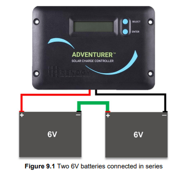
Series – Parallel connection of batteries (12V)
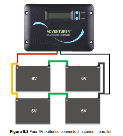
Fig. 9.3 shows two strings in parallel; each string consists of two 6V batteries in series. For example, say each battery has 225 Ah. Each string would have a voltage of 12V with a capacity of 225 Ah. When these strings are paralleled, the total capacity of the battery bank will be 12V at 450Ah. Notice that the cables connecting the batteries in series and parallel are of heavier gauge than the ones coming from the controller. These cables have to be of heavier gauge because when power is drawn from an inverter, it involves large amounts of current. This interconnection cable is often sized according to the power of the inverter. Also, the negative cable from the controller to the battery should be placed at the opposite end of the battery bank. Figure 9.3 shows this connection.
Series connection of batteries (24V)
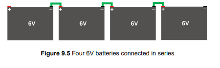
Wiring two 12V batteries in series as shown in Fig 9.4 will result in a 24V system. The same idea applies if you place four 6V batteries in series (Fig 9.5). Remember that when batteries are in series, the voltages add, but the total capacity of a string of batteries stays the same. For example, if two 12V batteries with 150Ah rating are wired in series, the resulting system would be 24V at 150Ah. Because of this, it is mandatory that the batteries are identical when they are wired in series.
Series-Parallel connection of batteries (24V)
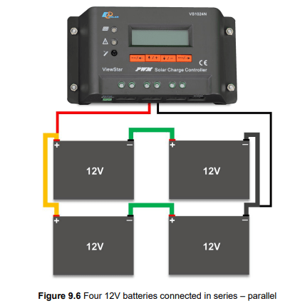
Multiple strings of batteries can be wired in parallel to increase the capacity. Figure 9.6 shows a battery bank with two strings of batteries. Each string consists of two 12V batteries in series. For example, if wiring four 12V/150Ah batteries like as shown in Figure 9.6, then each string will have a total capacity of 24V/150Ah. By paralleling these strings, the total capacity would be 24V/300Ah. Because of this, it is mandatory that the batteries are identical. Each parallel string can also consist of 4x6V batteries to make 24V per string as shown in Figure 9.5. Remember that the negative cable from the controller to the battery should be placed at the opposite end of the battery bank.
Inverter Wiring
General information about power inverters
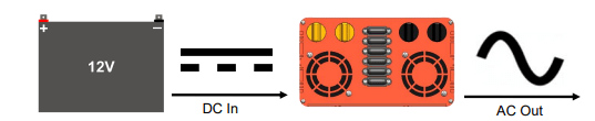
A power inverter, or inverter, is an electrical device that changes direct current (DC) to alternating current (AC); the converted AC can be at any required voltage and frequency with the use of appropriate transformers, switching, and control circuits.
Warning! Please read these instructions carefully before attempting to carry out any installation and wiring. Contact Technical support for any questions concerning the installation.
This equipment should be installed, adjusted, and serviced by qualified electrical maintenance personnel familiar with the construction and operation of solar/electrical equipment and the hazards involved. Failure to observe this precaution may result in bodily injury and/or damage to property.
Wiring instructions
Step 1: Select the right input voltage Input voltage can be 12V/24V/48V depending on which products are used. It is recommended that the inverter be powered by a battery or battery bank, as the current drawn from the inverter can become extremely high.
Step 2: Connecting inverter to battery Set the switch to OFF position (inverter and appliances). Connect the battery cables to their respective colors on the inverter i.e. black cable goes to the black terminal on the inverter, and the red cable goes to the red terminal on the inverter.
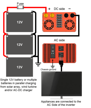
Figure 10.2 Inverter wiring diagram
Please refer to Fig. 3. Each end of the battery tray cables should have a “ring terminal” type of connector. These connectors make it easy to achieve a secure and strong connection. Once the cables are connected and bolted down to the inverter, connect the black cable to the negative post of the battery (-). Then, connect the red cable to the positive post of the battery (+). If connecting to a battery bank, make sure that the black cable connects to the negative battery post (-) at the end of the bank (opposite to the positive battery post as shown on Fig. 3). It is recommended that a fuse be placed on the hot line (positive) between the battery and inverter. Please refer to the owner’s manual for the proper wire gauge size and fuse ratings for each inverter.
Ground! The negative battery terminal and the chassis ground of the inverter should be connected to a system ground. This is a safety measure to prevent electrical shock!
NOTE: The charge controller and the inverter should be connected to the same battery terminals (same connecting points shown in Figure 10.2), no exceptions.
Step 3: Connecting electrical appliances to inverter
Caution! Make sure the power load is within the rated power of the inverter. The start power of the appliances should not exceed the peak power of the inverter.
Once the devices are connected to the AC outlet, they are ready to be powered. When the inverter is not in use, it is recommended that you turn off the inverter (switch in OFF position).