Loading ...
Loading ...
Loading ...
28
En
Preparation
05
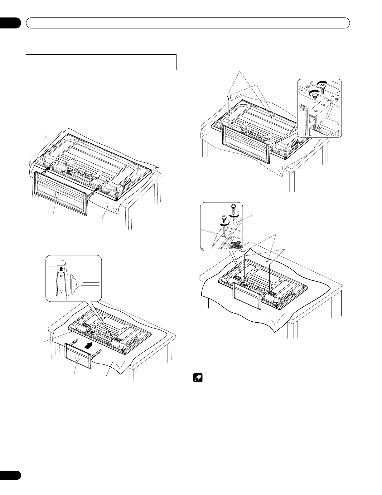
Attaching the stand again
1 With the plasma display lying flat, fit the stand’s
support columns to the bottom of the plasma display as
indicated by the arrows, then slowly insert them.
• Be extremely careful not to insert the support columns of
the stand into any part of the plasma display other than the
stand insertion slots. Doing so might damage the plasma
display panel or its ports or result in warping of the stand.
2 Attach the stand at the points indicated by the arrows
and tighten the installation bolts (2) and (1) firmly using
a screwdriver.
Installation bolts (1): M8 x 23 mm (black) for PRO-110FD
M6 x 20 mm (black) for PRO-150FD
Installation bolts (2): M8 x 40 mm (black) for PRO-110FD
M6 x 20 mm (black) for PRO-150FD
3 Replace the plasma display to stand upright.
For speaker installation, see Installing the Pioneer
speaker on page 19.
Note
• Be sure to install the plasma display in a flat, stable location.
• Insert the screws into the holes vertically and tighten them.
• Place a sheet or protective cover to protect the display from
scratches or damage.
• Work only with the plasma display lying flat on a table or similar
surface.
• When lying the plasma display down, be careful not to scratch
or damage it.
• If the speaker has been installed, it is recommended to detach
the speaker before attaching the stand.
• Steps for attaching the stand are the same for PRO-150FD
and PRO-110FD (use the screw holes with “T” inscribed).
Sheet
Plasma
display
Insert the stand into the
plasma display so that an
arrow with “FRONT/FACE
AVANT” mark inscribed at
the bottom of the stand
indicates downward.
(PRO-150FD)
Insert the stand into the
plasma display so that an
arrow with “FRONT/FACE
AVANT” mark inscribed at
the bottom of the stand
indicates downward.
Sheet
(PRO-110FD)
Plasma
display
Line up the column supports
with the bottom of the plasma
display, as indicated in the
accompanying diagram.
Installation bolts (1)
(Step 2)
Installation bolts (2)
(Step 1)
(PRO-150FD)
Screw hole with
“T” inscribed
Installation bolts (1)
(Step 2)
Installation bolts (2)
(Step 1)
(PRO-110FD)
PRO150FD.book Page 28 Tuesday, June 12, 2007 12:37 PM
Loading ...
Loading ...
Loading ...