
MU-STIX-CTL
USER MANUAL
MU-STIX-CTL CONTROLLER PLATFORM

Page
2
of
19
MU-STIX-CTL User Manual
Contents
Introduction ......................................................................................................................................................................................................... 3
Features ......................................................................................................................................................................................................... 3
Product Overview ............................................................................................................................................................................................ 3
Box Contents ................................................................................................................................................................................................ 3
Te ch n ic a l S p ec i fic a ti o ns ........................................................................................................................................................................ 4
Front and Rear Panel Overview ......................................................................................................................................................... 5
Rack Mount / Rubber Feet Installation ................................................................................................................................................. 6
Rack Mounts ................................................................................................................................................................................................ 6
Mounting Feet Assembly ....................................................................................................................................................................... 6
Initial Setup ......................................................................................................................................................................................................... 6
Connecting Devices ................................................................................................................................................................................. 7
Cascading - Host and Client Roles ................................................................................................................................................... 7
Accessing the Web Interface .................................................................................................................................................................... 8
Navigating the Web Interface .................................................................................................................................................................. 9
Config Page (Monitoring) .................................................................................................................................................................... 10
To ol b ar ...................................................................................................................................................................................................... 11
System .......................................................................................................................................................................................................... 12
IP Settings ............................................................................................................................................................................................... 12
Role Control ........................................................................................................................................................................................... 13
Hardware ................................................................................................................................................................................................ 13
Versions .................................................................................................................................................................................................... 14
Warranty ........................................................................................................................................................................................................... 15
Obtaining Warranty Service .............................................................................................................................................................. 16
Disclaimer of Warranty ........................................................................................................................................................................ 17
Support ........................................................................................................................................................................................................ 18
Legal Notices ............................................................................................................................................................................................ 18
Page
3
of
19
MU-STIX-CTL User Manual
Introduction
The Murideo MU-STIX-CTL is a high-density, scalable controller platform designed to manage up to 48x
MU-STIX HDMI analyzer and generator devices. The MU-STIX-CTL provides centralized signal analysis
and generation with a user-friendly web-based interface. Multiple units can be cascaded, enabling control
of up to 960x MU-STIX devices simultaneously.
This manual provides installation, configuration, and troubleshooting instructions for the MU-STIX-CTL.
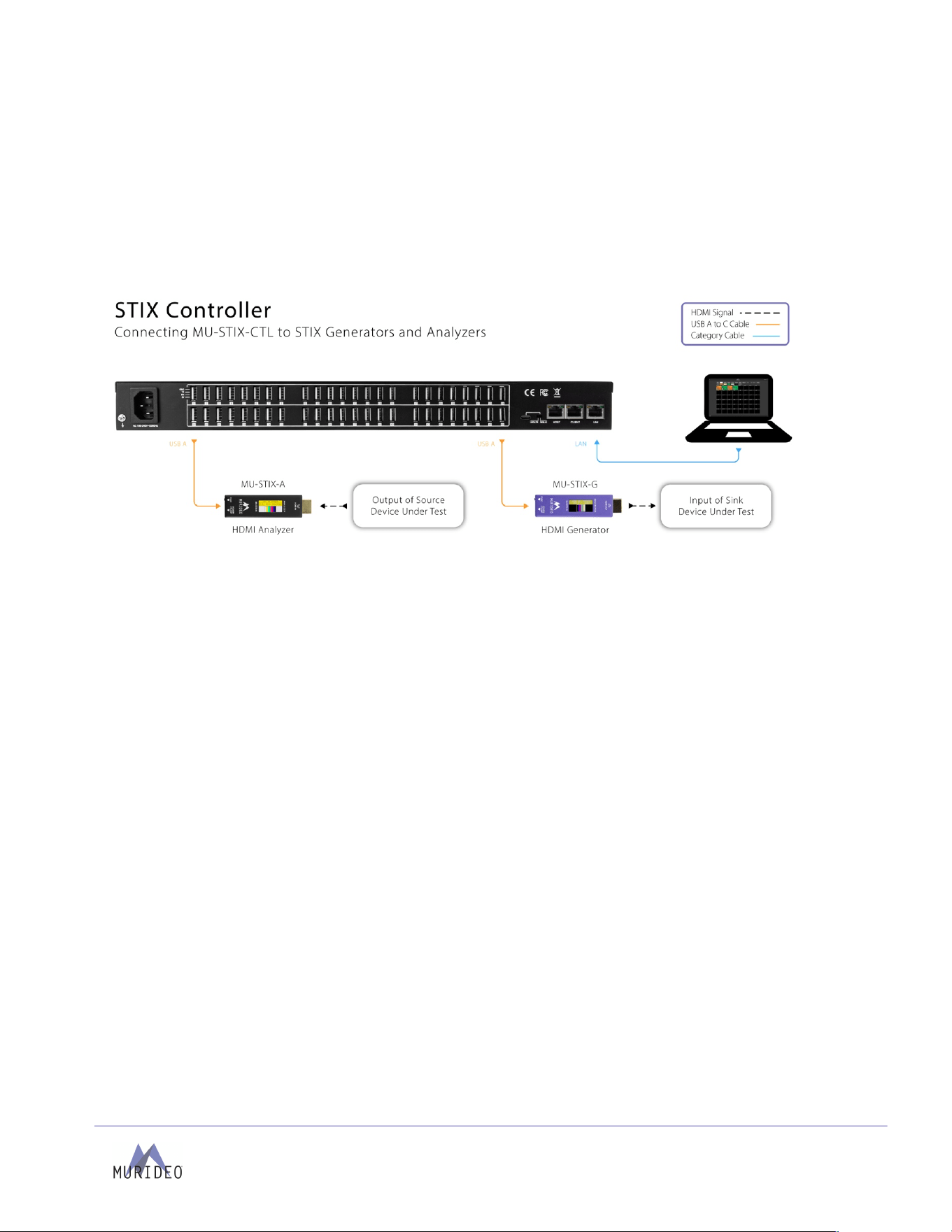
The diagram below shows the MU-STIX-CTL in a typical installation:
Features
• Supports up to 48x MU-STIX analyzer and generator devices per controller
• Web-based interface for centralized control and monitoring
• Cascade capability for large-scale HDMI testing (up to 20x MU-STIX-CTL units)
• Front-panel LED indicators for connection and device status
• USB Type-A ports for device connectivity and power distribution
• HDMI output and 2x USB Type-A ports for local UI display and control
• Rack-mountable 1RU chassis
Product Overview
Box Contents
• (1x) Murideo MU-STIX-CTL Unit
• (1x) Power Cable
• (2x) 1U Rack Mounting Brackets
• (6x) Screws for Mounting Brackets
• (4x) Rubber Feet
• (4x) Rubber Feet Screws
• (1x) Ground Wire

Page
4
of
19
MU-STIX-CTL User Manual
Te ch ni ca l Sp ec ifi ca ti on s
Ports
USB
48x Type-A (MU-STIX devices)
2x Type-A DEVICE (Mouse, Keyboard)
1x Type-C (ISP)
HDMI Output
HDMI 2.0, Type-A, Female (UI)
RJ45
1x LAN (UI)
1x HOST
1x CLIENT
Power
IEC 320-C14, male
Ground
Grounding terminal
Control
Web Interface
Yes, LAN
ISP
USB Type-C
Environmental
Operating Temperature
23 to 125° F (-5 to 51° C)
Storage Temperature
-4 to 140° F (-20 to 60° C)
Humidity Range
5-90% RH (No Condensation)
Power
Power Consumption (Total)
7 W (no STIX attached)
150 W Maximum (48x STIX attached)
Power Supply
Input: 100-240 VAC ~ 50/60 Hz
Physical / Dimensions
Mounting
1-RU Rack Mounting Brackets
Rubber Feet
Dimensions (Unit
Length/Width/Height)
mm: 259 X 439.7502 X 44.45
inches: 10.196 X 17.313 X 1.75
Dimensions (Packaged
Length/Width/Height)
mm: 565 x 375 x 125
inches: 22.24 x 14.76 x 4.92
Weight (Unit)
8.25 lbs. (3.74 kg)
Weight (Packaged)
10.42 lbs. (4.73 kg)
Regulatory
CE/FCC/UL
Product Warranty
2 Years
*Specifications subject to change without notice. Mass & dimensions are approximate
Page
5
of
19
MU-STIX-CTL User Manual
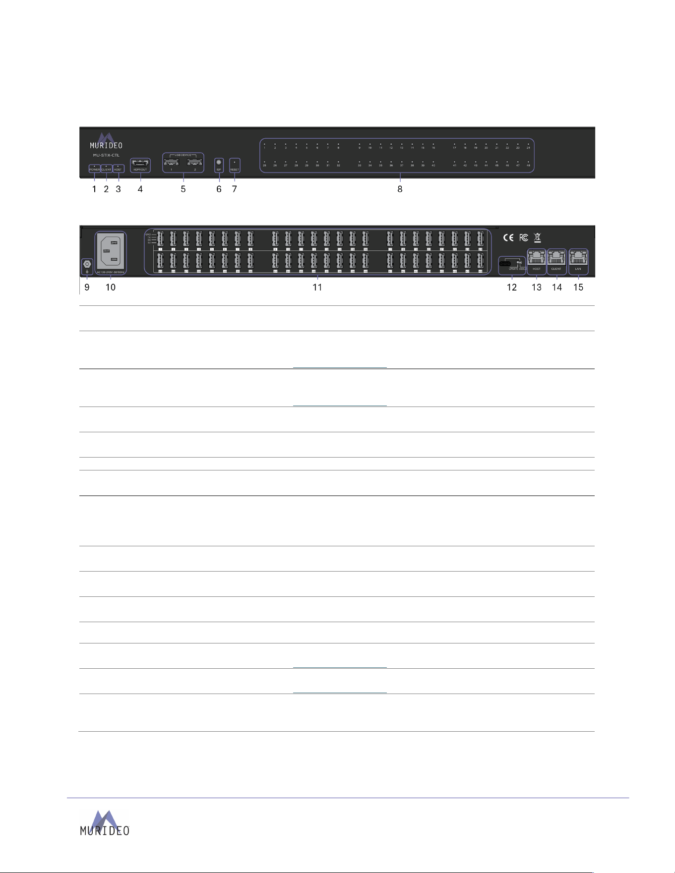
Front and Rear Panel Overview
Front Panel
Rear Panel
1
Power LED
•
Blue LED status indicator light
•
Solid blue indicates power is present on the unit
2
Client LED
•
Green LED status indicator light
•
Solid green indicates a Client unit is connected
•
See Host and Client Roles section for details
3
Host LED
•
Green LED status indicator light
•
Solid green indicates a Host unit is connected
•
See Host and Client Roles section for details
4
HDMI Output
•
19-pin HDMI Type-A female connector port
•
HDMI 2.0 output for local access to user interface
5
USB Device Ports
•
(2x) USB Type-A connector ports
•
Connect mouse/keyboard for local user interface control
6
ISP Button
•
Button for servicing by Murideo Te c hn i ca l Su p p o rt
7
Reset Button
•
Pin-hole button
•
Push button to reset unit
8
Status LEDs
•
(48x) Green LED status indicator lights
•
Off: No data connection or link established
•
Flashing: MU-STIX device connected with no signal
•
Solid On: MU-STIX device connected with good signal
9
Ground
•
Ground screw
•
Connect wit the ground wire provided to the conducting parts
10
Power In
•
IEC 320-C14, male power connector
•
Power input to unit
11
USB Device Ports
•
(48x) USB Type-A connector ports
•
Connect USB cable to MU-STIX devices
12
USB Type-C
DIP Switch
•
Proprietary service port and DIP switch for Murideo Technical Support
13
Host
•
8-pin RJ45 female connector
•
See Host and Client Roles section for details
14
Client
•
8-pin RJ45 female connector
•
See Host and Client Roles section for details
15
LAN
•
8-pin RJ45 female connector
•
Connect to the LAN or router for remote user interface access

Page
6
of
19
MU-STIX-CTL User Manual
Rack Mount / Rubber Feet Installation
Rack Mounts
The Murideo MU-STIX-CTL can be mounted in a 1RU rack-style enclosure and is compatible with all
standard 19-inch rack mounts. The (2x) mounting brackets are included with the purchase of a unit.
1. Align the holes on the mounting brackets with the holes on both sides of the rack.
2. Attach the mounting brackets to the rack with rack screws (not included).
Mounting Feet Assembly
The (4x) rubber feet can be assembled to the unit with the (4x) provided mounting screws.
1. Align the holes on the rubber feet with the holes underneath the unit.
2. Attach the rubber feet to the unit with the provided screws.
Initial Setup
Make physical connections to the inputs and output devices using the following steps below. For the initial
setup, it is recommended to connect the MU-STIX-CTL to a display via HDMI and mouse/keyboard via
USB Type-A ports on the front of the unit. The user interface will be accessible for initial setup and for
remote access configuration.
Page
7
of
19
MU-STIX-CTL User Manual
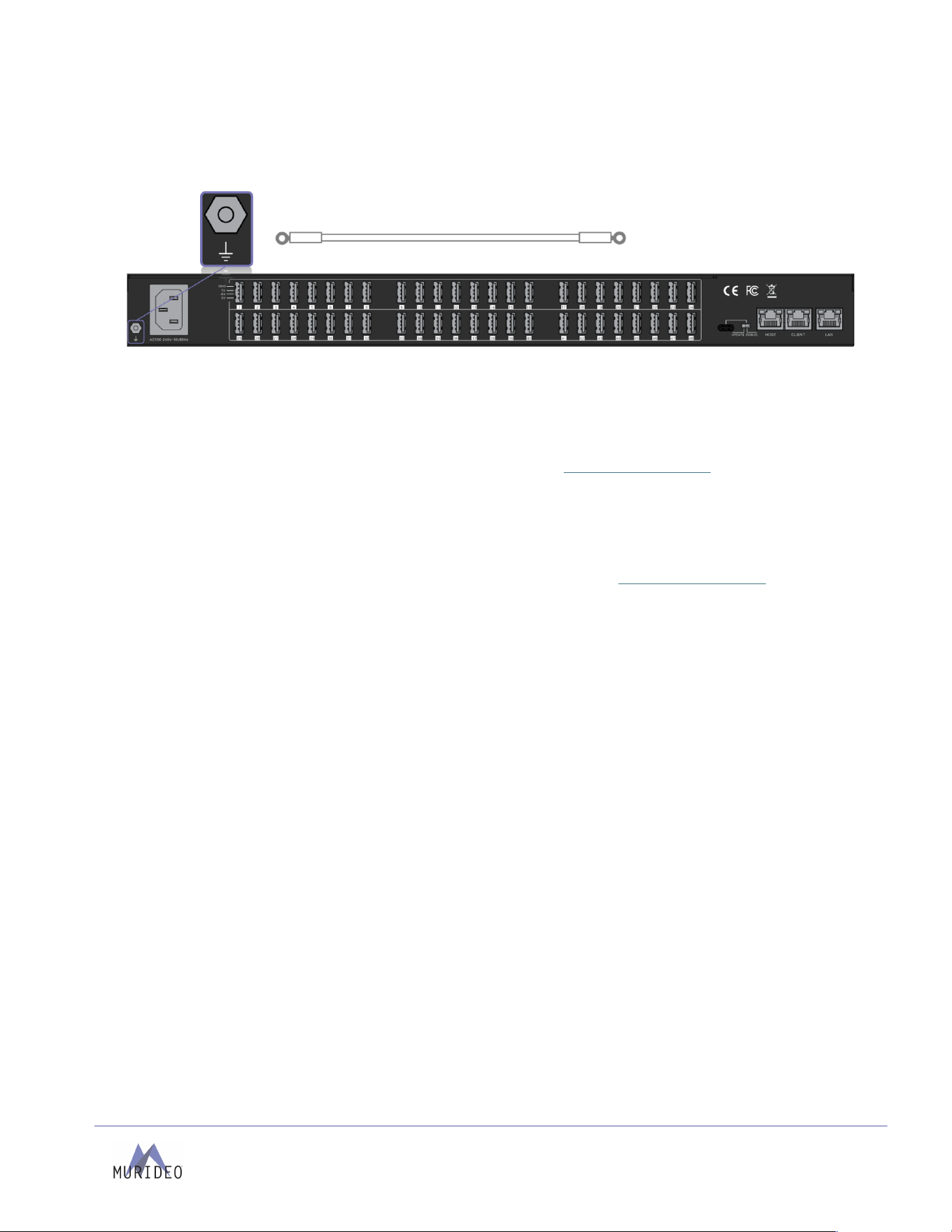
Connecting Devices
1. Use a screwdriver to attach the yellow ground cable to the pre-installed screw on the back of the
unit, then attach the other end to a suitable grounded object.
2. Connect the HDMI OUT port to a display via HDMI and mouse/keyboard to the USB DEVICE ports
on the front of the unit.
3. Connect the LAN port using an RJ45 ethernet cable to the local IP network or directly to a PC.
a. To a c ce s s t he us e r i nt er fa c e re m ot e ly re fe r t o t he System -> IP Settings section to
configure the IP address.
4. Connect the power cord to the Power In port on the back of the unit and plug the power cord into
a power source. The POWER LED should show a solid blue LED, indicating the unit is powered.
5. If the unit is used in Client mode for cascading, please refer to the Host and Client Roles for
additional connection and configuration steps.
6. Use a USB Type-A to USB Type-C cable to connect MU-STIX devices to the USB Type-A ports on
the rear of the MU-STIX-CTL. Once connected, refer to the corresponding green LED indicators on
the front panel:
a. Flashing Green: A MU-STIX device is connected via USB, but no HDMI signal is currently
detected (i.e., no HDMI Hot Plug Detect or 5V signal).
b. Solid Green: A MU-STIX device is connected and has successfully detected an HDMI
signal.
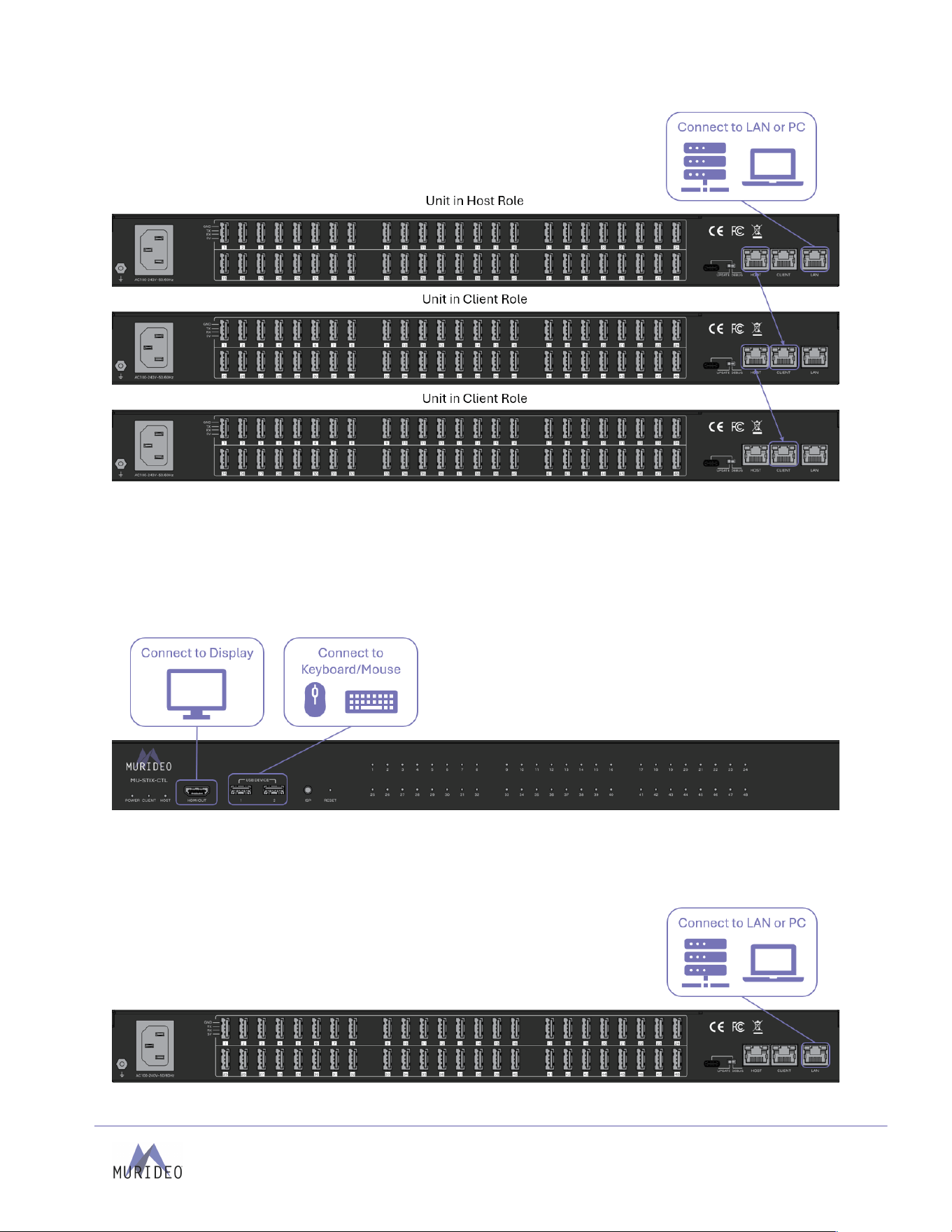
Cascading - Host and Client Roles
The MU-STIX-CTL provides a scalable solution for managing multiple HDMI test and analysis devices. It
features a user-friendly web interface that allows users to view connected devices, monitor video
thumbnails, and configure HDMI signal parameters.
Multiple MU-STIX-CTL units can be linked via Category wire, with a designated Host unit acting as the
primary controller and additional units functioning as Clients. Up to 20 units can be cascaded controlling
up to 960 MU-STIX analyzers and generators from a single user interface.
By default, the MU-STIX is in HOST mode. Before units are connected for cascading the user interface
should be accessed to change the default Role setting to Client in the System -> Role Control menu.
Connect Host and Client ports according to the following diagram to cascade units. –
Page
8
of
19
MU-STIX-CTL User Manual
Accessing the Web Interface
The MU-STIX-CTL web interface can be accessed in two ways:
1. Local Access: Connect a display to the HDMI output on the front of the unit. Then, connect a
mouse and keyboard to the USB Type-A device ports to navigate the interface directly.
2. Remote Access: Connect the LAN port to a PC, laptop, or network router. Open a web browser
and access the interface via the assigned IP address over HTTP.
Page
9
of
19
MU-STIX-CTL User Manual
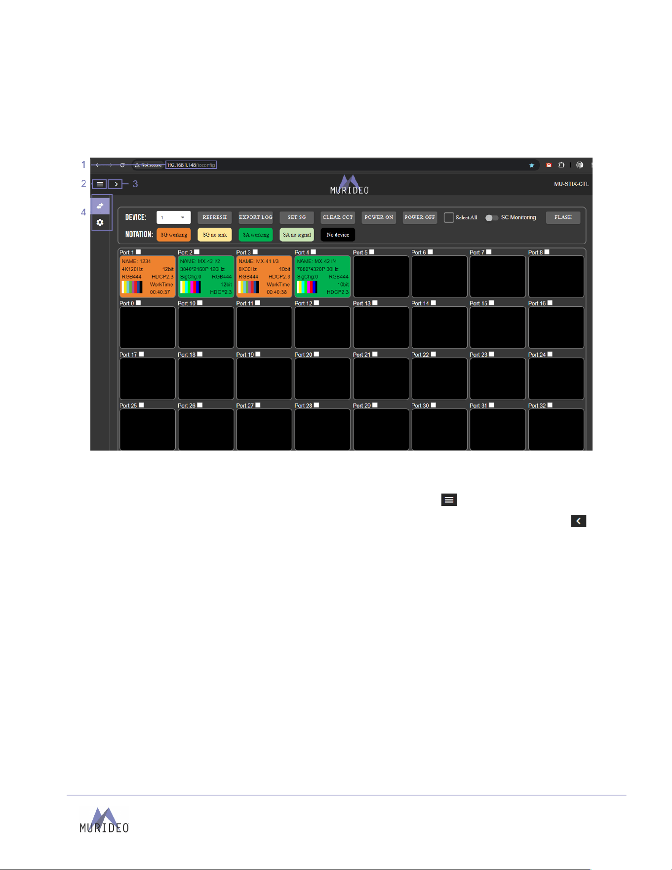
Navigating the Web Interface
The MU-STIX-CTL features a built-in User Interface (UI) that can be accessed through a web browser for
configuration and control. Different tools and settings can be selected from the tab pages - located on the
left side of the screen, inside the navigation menu column.
1. Enter the unit’s IP address into a web browser, such as Chrome or Edge, to access the Web
UI.
2. To h i de th e n a vi g at i on me n u, s el e ct th e
hamburger menu
icon .
3. To h i de th e n a vi g at i on me n u t ex t an d s h ow o n ly t he me n u i co n s, se l ec t th e
left arrow
icon .
4. To n a vi g at e t hr ou g h t h e d iff e r en t p ag e s, s el e ct th e i n di v i du a l
tab pages
from the navigation
menu. This will highlight the tab page in green to indicate the currently selected page.
Page
10
of
19
MU-STIX-CTL User Manual
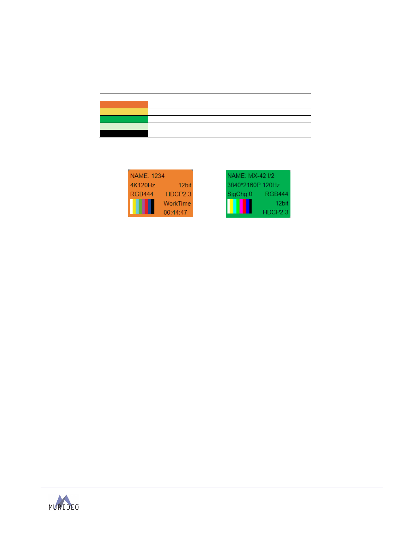
Config Page (Monitoring)
The Config page is the default landing page of the user interface. The page features 48 tiles representing
either a MU-STIX analyzer or generator. Each tile is color-coded according to the type of MU-STIX
connected and its HDMI connection state.
Color Code
Notation
Signal generator connected; hot plug detected
Signal generator connected; no hot plug detected
Signal analyzer connected; hot plug detected
Signal analyzer connected; no hot plug detected
No device detected
Each tile features a name, resolution timing, video sampling, color bit depth and HDCP version as well as a
thumbnail of the generated or analyzed video. Note, for generators, mousing over the thumbnail will show
Signal Sink Loss count.
Signal Generator Tile
Signal Analyzer Tile
Page
11
of
19
MU-STIX-CTL User Manual
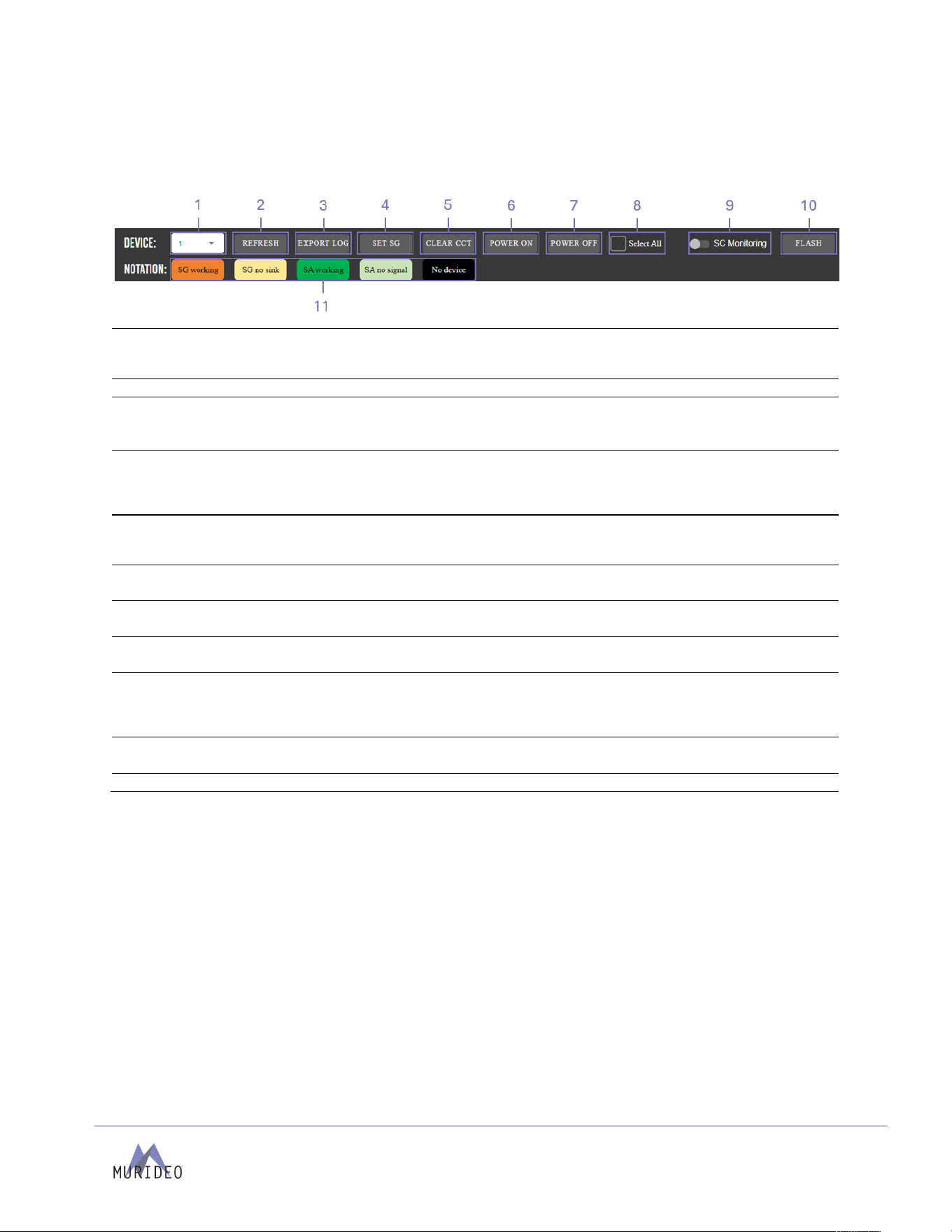
Too lbar
The toolbar at the top of the tile menu has buttons to perform functions to the MU-STIX devices. The
toolbar also has a legend for the color-coding of the tiles.
1
Device
•
Drop-down menu for selecting cascaded MU-STIX-CTL devices
•
Navigate between pages to access all connected devices when using multiple
MU-STIX-CTL units.
2
Refresh
•
Button to refresh the status tiles of the connected MU-STIX devices
3
Export Log
•
Export logs of a selected MU-STIX device or devices
•
Log is exported to .log file
•
Bulk export logs by selecting multiple tiles or using the Select All function.
4
Set SG
•
Dialog box to configure MU-STIX device settings such as Timing, Color Space,
Output Pattern, Color Depth and HDCP version.
•
Bulk configure MU-STIX devices by selecting multiple tiles or using the Select
All function.
5
Clear CCT
•
Clear Signal Loss and Signal Change Monitoring Counters on MU-STIX
analyzing devices
•
Bulk clear counters by selecting multiple tiles or using the Select All function.
6
Power On
•
Power On connected MU-STIX devices
•
Bulk power on by selecting multiple tiles or using the Select All function.
7
Power Off
•
Power Off connected MU-STIX devices
•
Bulk power off by selecting multiple tiles or using the Select All function.
8
Select All
•
Select all tiles on the main homepage.
•
Useful for bulk configuration, power cycling, or log export from devices.
9
SC Monitoring
•
Enables Signal Change Monitoring on the selected MU-STIX devices tiles
•
Te s t f ra m e to f ra m e di ffe re nc e i n an HD M I si g na l . T h is ca n b e u s ed to d i ag n o s e
intermittent issues in a system. This test requires a still or stationary image
generated by the HDMI source.
10
Flash
•
Causes the LCD screen on connected MU-STIX devices to flash on and off.
•
This is useful for identifying MU-STIX devices in testing environments.
11
Notation
•
Legend for color-coding status of tiles.
Page
12
of
19
MU-STIX-CTL User Manual
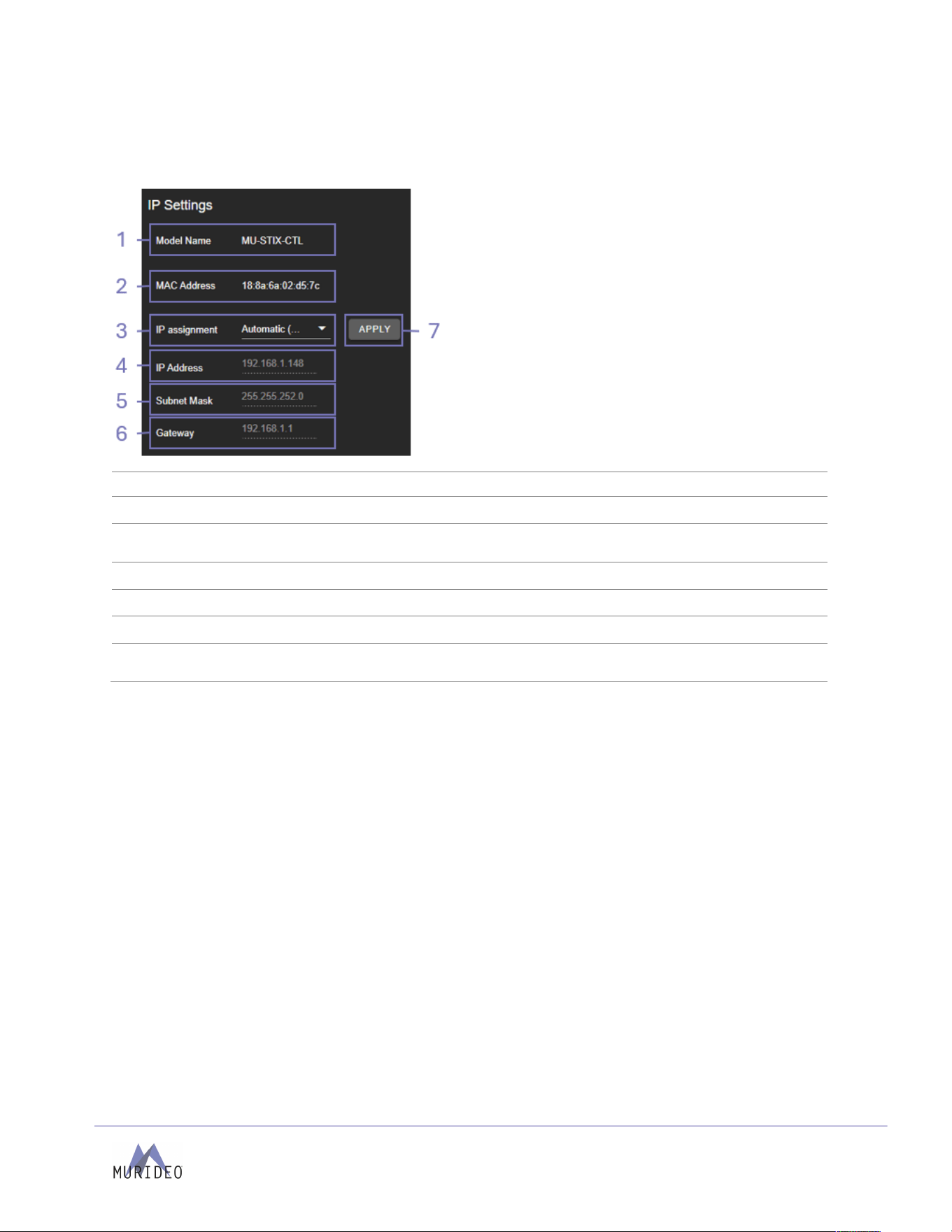
These will be assigned by a DHCP reservation from
the router when the
IP Assignment
is set to
Automatic
, or they can be manually entered in
when the
IP Assignment
is set to
Manual
.
Select the
Apply
button when manually entering in
the
IP Assignment
,
IP Address
,
Subnet Mask
, and
Gateway
for changes to take effect.
System
IP Settings
1
Model Name
Shows the unit’s AVPro Edge model number.
2
MAC Address
Shows the unit’s unique MAC address.
3
IP Assignment
Select the dropdown menu to set the unit’s IP mode to
DHCP
(default) or
Manual (Static IP)
, then select the
Apply
button.
4
IP Address
Shows the unit’s IP address.
5
Subnet Mask
Shows the unit’s subnet mask.
6
Gateway
Shows the unit’s default gateway.
7
Apply
Clicking the Apply button applies to any changes made to IP
assignment, IP Address, Subnet Mark and Gateway.
Page
13
of
19
MU-STIX-CTL User Manual
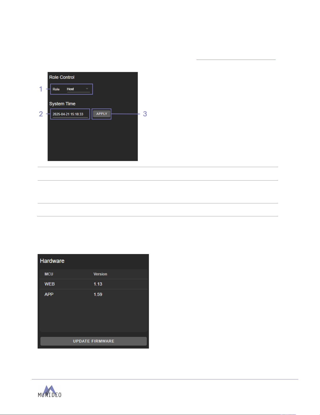
Role Control
This menu is used to configure the Role of the MU-STIX-CTL device when cascaded. For additional details
on cascading units for dense monitoring of HDMI signals, refer to the Cascading - Host and Client Roles
section.
1
Role
Assigns the role of the MU-STIX-CTL when cascaded with other
units. The default setting is Host.
2
System Time
Shows the current System Time for the MU-STIX-CTL. The System
Time can be configured manually by editing the date/time. This
System Time is applied to all connected MU-STIX devices and is
used to timestamp logs.
3
Apply
Clicking the Apply button applies to any changes made to Role
Control and System Time settings.
Hardware
This section shows the MU-STIX-CTL devices current firmware versions and has the option to update the
firmware.
Page
14
of
19
MU-STIX-CTL User Manual
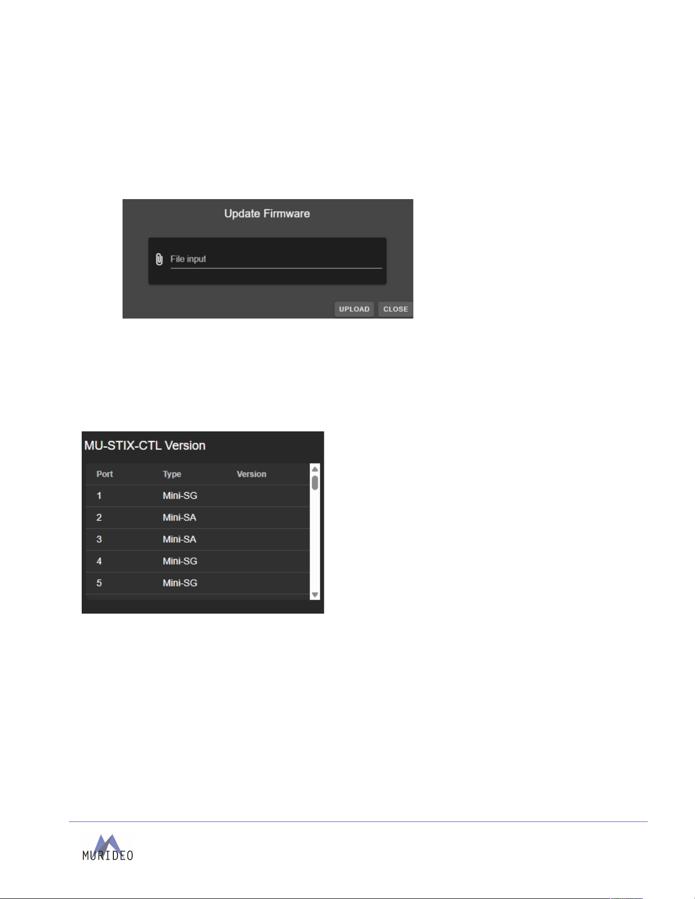
Updating Firmware
1. Download the latest firmware from Murideo’s website.
2. Click the Update Firmware button in the Hardware section in the web interface.
3. Upload the firmware file by clicking the paperclip icon. Once uploaded, initiate the update
process by clicking the Upload button. The unit will now begin installing the latest versions of
firmware. DO NOT refresh the webpage or power off the unit during the update.
4. Once the progress bar reaches 100%, select the
Close
button. The unit will automatically reboot
once the firmware updates are complete. After the unit reboots, refresh the webpage.
Versions
This section of the interface shows the Port number, the Type of MU-STIX device that is connected to the
port and the version of firmware running on the MU-STIX device.

Page
15
of
19
MU-STIX-CTL User Manual
Warranty
AVPro Global Holdings (DBA MURIDEO) offers a 2-year international limited warranty for its Murideo
products. Any product first sold to you is guaranteed to be free from defects in both components and
workmanship under regular use. The warranty period commences on the date the item ships.
Attention:
Your invoice with t he date o f purchase, model number, and seri al n umber of t he p roduct is p roof of t he
date of purchase. The international Limited Warranty is applicable and shall be honored in every country
where MURIDEO or its Authorized Service Providers offer warranty service subject to the terms and
conditions provided in this international Limited Warranty Statement. Products included in this warranty:
•
Murideo SEVEN Series Generators
•
Murideo SIX Series Generators
•
Murideo SIX Series Analyzers
•
Murideo Fox & Hound Series
•
Murideo HDMI Test Monitor Series
•
Murideo GAX Series
•
Murideo STIX Series
During the warranty period, the defective hardware of Murideo products will be either repaired or
replaced with new or like-new products at Murideo's discretion. This International Limited Warranty covers
the costs of service parts and labor required to restore your product to fully functional condition.
MURIDEO will, at its discretion, repair or replace any defective products or parts covered by this
International Limited warranty with refurbished parts of the product that are equivalent to new or like new
products in both functionality and performance. A product or part repaired or replaced under this
International Limited Warranty shall be covered for the remainder of the original warranty period applying
to the product or part or for 90 days, whichever expires last. All exchanged parts and products under this
International Limited Warranty will become MURIDEO's property.

Page
16
of
19
MU-STIX-CTL User Manual
Obtaining Warranty Service
Warranty service or Returned Merchandise Authorization (RMA) under this International Limited Warranty
will be honored only if claims are made within the warranty period. The process for notifications to
MURIDEO or products outside the warranty period will be the same, but charges may apply. Contact
details may be obtained on the MURIDEO website: https://www.murideo.com/
Customers are requested to perform the following actions before claiming MURIDEO product is defective:
•
Owner must notify MURIDEO, during the warranty period, in writing of the alleged defect and
allow MURIDEO a reasonable opportunity to inspect the allegedly defective product;
•
No Product may be returned without MURIDEO’s consent. The MURIDEO RMA# must accompany
all returns, and all returns must be delivered to MURIDEO within the warranty period.
•
Owner may, then at its own expense, return the allegedly defective Product, freight pre-paid and
in the original packaging, accompanied by a brief statement explaining the alleged defect to
MURIDEO;
•
If MURIDEO determines that any returned Product is not defective, or if MURIDEO determines that
the warranty does not cover the defect, MURIDEO will return the Product to the Owner at the
Owner’s expense, freight collect, and Owner agrees to pay MURIDEO reasonable cost of handling
and testing.
•
Upon determining that the returned product is defective, the Owner will need to present the
invoice showing the original purchase transaction to receive warranty service. If shipping the
product, the Owner will need to package it carefully and send it, transportation prepaid by a
traceable, insured method, to the MURIDEO Service Center. Package the product using adequate
padding material to prevent damage in transit. The original container is ideal for this purpose.
Include the RMA #, your name, return shipping address, email address, and telephone number
where you may be reached during business hours inside the shipping package with the unit. Any
replacement unit will be warranted under these Terms and Conditions for the remainder of the
original warranty period or ninety (90) days, whichever is longer. For important Aps on operating
and troubleshooting the product, refer to the user manual, which can be downloaded from our
website, http://www.murideo.com/.

Page
17
of
19
MU-STIX-CTL User Manual
Disclaimer of Warranty
THIS WARRANTY IS EXPRESSED INSTEAD OF ALL OTHER WARRANTIES, EXPRESSED OR IMPLIED,
INCLUDING THE IMPLIED WARRANTY OF MERCHANTABILITY, THE IMPLIED WARRANTY OF FITNESS
FOR A PARTICULAR PURPOSE AND OF ALL OTHER OBLIGATIONS OR LIABILITIES ON MURIDEO’S
PART, AND IT NEITHER ASSUMES NOR AUTHORIZES ANY OTHER PARTY TO ASSUME FOR MURIDEO
ANY OTHER LIABILITIES. THE FOREGOING CONSTITUTES THE BUYER’S SOLE AND EXCLUSIVE
REMEDY FOR THE FURNISHING OF DEFECTIVE OR NONCONFORMING PRODUCTS AND MURIDEO
WILL NOT, IN ANY EVENT, BE LIABLE FOR COST OF SUBSTITUTE OR REPLACEMENT, COST OF
FACILITIES OR SERVICE, DOWNTIME COSTS, LOSS OF PROFITS, REVENUES OR GOODWILL, RELIANCE
DAMAGES, LOSS OF DATA, LOSS OF USE IF OR DAMAGE TO ANY ASSOCIATED EQUIPMENT, OR ANY
OTHER INDIRECT, INCIDENTAL, SPECIAL, OR CONSEQUENTIAL DAMAGES BECAUSE OF THE FACT
THAT SUCH PRODUCTS WILL HAVE BEEN DETERMINED TO BE DEFECTIVE OR NONCONFORMING.
THE RIGHTS AND OBLIGATIONS OF THE PARTIES UNDER THIS AGREEMENT SHALL NOT BE
GOVERNED BY THE PROVISIONS OF THE 1980 U.S. CONVENTION ON CONTRACTS FOR THE
INTERNATIONAL SALE OF GOODS OR THE UNITED NATIONS CONVENTION ON THE LIMITATION
PERIOD IN THE INTERNATIONAL SALE OF GOODS, AS AMENDED (COLLECTIVELY,
THE“CONVENTIONS”); RATHER, THE RIGHTS AND OBLIGATIONS OF THE PARTIES SHALL BE
GOVERNED BY THE LAWS OF THE STATE of SOUTH DAKOTA, INCLUDING ITS PROVISIONS OF THE
UNIFORM COMMERCIAL CODE, AS APPLICABLE. FOR THE AVOIDANCE OF DOUBT, THE
CONVENTIONS ARE HEREBY EXCLUDED.
This Limited Warranty gives you specific legal rights. You may also have other rights that vary from state
to state or country to country. You are advised to consult applicable state or country laws to fully
determine your rights. Some jurisdictions do not allow the exclusion or limitation of special, incidental, or
consequential damages or limitations on how long a warranty lasts, so the above exclusion and limitation
may not apply to everyone.

Page
18
of
19
MU-STIX-CTL User Manual
Support
For service and support, contact your local dealer. To find your dealer or to contact MURIDEO support, go
to: https://support.murideo.com or call +1-605-330-8491 for worldwide technical support.
Legal Notices
MURIDEO® Logos are trademarks or registered trademarks of AVPro Global Holdings, Inc. in the United
States or other countries. ISF® and the ISF logo are trademarks or registered trademarks used under
license from Imaging Science Foundation, LLC. in the United States or other countries. All other
trademarks and registered trademarks are the property of their respective owners in the United States or
other countries. The absence of a trademark symbol does not constitute a waiver of Silicon Image’s
trademarks or other intellectual property rights about a product name, logo, or slogan. Limitation of
Liability MURIDEO reserves the right to refuse warranty service of products under disputable conditions.
MURIDEO also holds the right to declare the final decision on whether products are within warranty
conditions. The following actions and damages will result in voiding the limited warranty:
•
Damage caused by acts of nature, such as fire, flood, wind, earthquake, lightning, etc.
•
Damage or incompatibility caused by failure to perform a proper installation or to provide an
appropriate operational environment for the product, including but not limited to unstable
wired/wireless network connection and phone lines, insufficient grounding, external electro-
magnetic fields, direct sunlight, high humidity, and vibration.
•
Damage caused by impact with other objects, dropping, falls, spilled liquids, or submersion in
liquids.
•
Damage caused by unauthorized repair or disassembling of the product.
•
Damage caused by abuse, misuse, mishandling, or misapplication.
•
Damage caused by third-party peripherals (including but not limited to visible damages on the
motherboard or other electronic parts of the product, such as burn spots after electric discharge,
melting fusing, splitting, etc.)
•
Any unauthorized software or modification of built-in software not approved by MURIDEO.
•
The product's serial number (or serial number stickers of its parts) has been modified, removed,
blurred, or damaged.
•
Defects caused by transportation, handling, or customer abuse.

Page
19
of
19
MU-STIX-CTL User Manual
Thank you for choosing MURIDEO!
Please contact us with any
questions, we are happily at your
service!
2222 E 52
nd
Street North, Sioux Falls, SD 57104
Support:
Phone: +1-877-886-5112
Email: support@avproedge.com
