
1
Fox & Hound 8K Test Kit
MU-FXHD-GEN-8K
HDMI 2.1 40Gbps FRL Audio/Video Generator & Analyzer

INTRODUCTION .............................................................................. 3
FOX/GENERATOR FEATURES ............................................................... 3
HOUND/ANALYZER FEATURES ............................................................. 3
WHATS IN THE BOX ......................................................................... 4
SPECIFICATIONS ............................................................................. 4
AUDIO/VIDEO DISTRIBUTION SYSTEMS - OVERVIEW ............................... 5
FRONT PANEL OVERVIEW: FOX /GENERATOR .......................................... 6
FRONT PANEL OVERVIEW: HOUND/ANALYZER ......................................... 9
VIDEO GENERATOR: TIMING & RESOLUTION ....................................... 12
VIDEO GENERATOR: AUTO BUTTON ................................................... 14
VIDEO GENERATOR: HDCP BUTTON ................................................... 15
VIDEO GENERATOR: HDCP INDICATOR LED ......................................... 15
VIDEO GENERATOR: AUDIO BUTTON ................................................. 16
VIDEO GENERATOR: COLOR BUTTON ................................................. 16
VIDEO GENERATOR: HDR BUTTON .................................................... 17
VIDEO GENERATOR: BACK BUTTON ................................................... 17
BASIC TROUBLESHOOTING - HDMI CABLE TEST .................................... 18
TROUBLESHOOTING DISTRIBUTED SYSTEM - HDCP ISSUE ....................... 20
BASIC TROUBLESHOOTING A DISTRIBUTION SYSTEM ............................. 22
TROUBLESHOOTING DISTRIBUTED SYSTEM - EDID ISSUE ....................... 24
REASONS TO COPY AN EDID TO THE ANALYZER .................................... 26
COMMON ISSUES DIAGNOSED EASILY WITH THE FOX AND HOUND TROUBLE-
SHOOTING KIT ............................................................................. 27
TROUBLESHOOTING TIPS ................................................................ 28
WARRANTY AND GETTING HELP ........................................................ 29
OBTAINING THE WARRANTY SERVICE ................................................. 30
DISCLAIMER OF WARRANTY ............................................................. 31
GETTING HELP .............................................................................. 32
LEGAL NOTICES ............................................................................ 32
2

Introduction
This 40Gbps Generator and Analyzer Testing Kit from Murideo was built as the ideal testing unit
for all custom and commercial integrators. The Fox & Hound comes with a 40Gbps Generator and
40Gbps Analyzer. These tools allow you to conrm correct bandwidth, HDCP, resolution, timing, HDR
metadata and many more options that could cause system hiccups if not treated correctly.
With devices like 8k displays and sources becoming normal for all video distribution systems, tons of
new video formats are coming with it. How are you going to test those new signals? That is why we
set out to develop a simple, aordable solution to troubleshoot system issues for today’s integrator.
The 8K Fox & Hound: A/V Testing and Troubleshooting Kit is a product that can produce and analyze
the newest and highest resolutions – 8k resolutions and refresh rates up to 120hz at 40Gbps. It’s also
aordable enough for every integrator to have on any install/service call!
3
· HDMI 2.1 Support 40Gbps Fixed Rate Link (FRL)
· 8K@60 4:2:0 10-bit Maximum Resolution
· Selectable Color Space
· Auto Detect (read EDID, generate preferred format)
· High Bit Depth – 8, 10, and 12 bit per pixel support
· HDR (High Dynamic Range) Support; HDR10 and HLG
· Selectable HDCP up to 2.3
· Portable - Battery Operated > Rechargeable batteries
included make eld troubleshooting much easier.
· Optimized Ergonomics – 2” LCD display and simple
menu system makes Fox very user friendly.
· Includes audio condence test tones > to make sure
audio is active on the HDMI line
· HDMI 2.1 Support 40Gbps Fixed Rate Link (FRL)
· Test HDMI Cables up to 40Gbps FRL, full TMDS testing
· View up to 40Gbps Video Content and Format Info
· Audio Condence Tests (2-Channel & Multichannel)
· Read, Write/Save any EDID (x2 savable Presets)
· Selectable HDCP up to 2.3
· Portable - Battery Operated > Rechargeable batteries
included make eld troubleshooting much easier.
· Optimized Ergonomics – 2” LCD display and simple
menu system makes Hound very user friendly.
· HDR (High Dynamic Range) Support
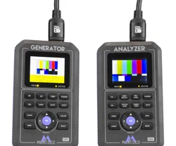
Fox/Generator
Features
Hound/Analyzer
Features
Questions regarding terminology in this manual please refer to the Murideo Support Community for
more information.
·Knowledge Base - Contains Technical Tips, Training Materials, and Articles.
·Community - Forum based community.
·Ticket System - Request support via our Ticket System.
4
Whats in the Box
· Fox-Generator
· Hound-Analyzer
· HardCase
· x212V2APowerSupplies
· x2MicroUSBCables
· x2HDMICables
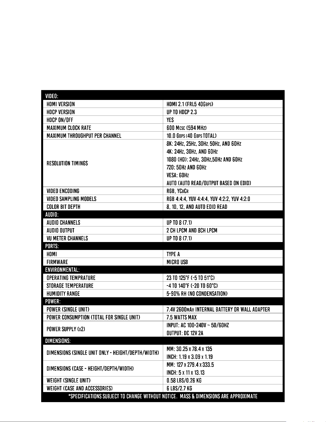
Specications

It is imperative to know and understand the interactivity of the devices regardless if the system is
simple or complex. Understanding the basics of systematic troubleshooting from source to display
(and everything in-between) will greatly improve your chances of resolving issues within the system.
5
Audio/Video Distribution Systems - Overview
All AV Systems are made of basically 3 main components:
· Sources – This is any device that outputs HDMI – Set top boxes, game consoles, computers and more.
This is a HDMI Transmitter device. Substitute the generator during system testing – use the analyzer to
test the output of any source for the desired timing characteristic.
· Repeaters – This is a combination device that can be connected between one or several sources and
sink devices – like an AVR (audio video receiver) or matrix switch. Use both generator and analyzer for
troubleshooting the devices and for system troubleshooting.
· Sinks – This is the display or projector – this is an HDMI Receiver device. Substitute the analyzer for
sinks during system testing – use the generator to test sinks by injecting a specic timing characteristic
expected to pass through distribution system.
In the diagram above you can see the basic components of an A/V system (#1 = source, #2
= distribution system, #3 = sink). Although this is a simple diagram, imagine there are several
devices (AVR, Distribution Amplier aka HDMI splitter, AVR, HDMI Extender, etc) in place of #2 (the
distribution system).
Example of a functioning system based on the diagram above:
1. Generator – generates test pattern (SMPTE Bars) at desired video format and HDCP version.
2. DISTRIBUTION SYSTEM - passes the signal (unaltered).
3. Analyzer – receives and displays the test pattern (SMPTE Bars) at desired video format and HDCP
version.

FRONT PANEL OVERVIEW: Fox /Generator
6
FromToptoBottom(LefttoRight)
1. HDCP Indicator LED – Indicates the presence of HDCP
ON - HDCP is enabled (Up to 2.3)
OFF - No HDCP detected
2. Status Indicator - Indicates that a Hot Plug event has occurred and there is a successful
connection between the source, sink, and repeaters in the system.
NOTE: See page(s) 12-13 for a full list of all available timing/resolutions from Vesa up to 8k.
3. 8K Button – Choose from a list of 8K timings up to 40 Gbps FRL.
4. 4K Button – Choose from a list of 4K timings up to 18 Gbps.
5. 1080 Button – Choose from a list of High Denition (HD) 1080 timings.
6. 720 Button – Choose from a list of High Denition (HD) 720 timings.
7. Power Button – Press and hold to power the unit on or o.

7
8. VESA Button - Choose from a list of VESA timings.
9. Auto Button – When pressed the generator will read the EDID from the sink device that it is
connected to. It will then output an A/V signal based on the preferred timing in the EDID.
Note: The battery charge level and Firmware versions are also on this page. To view this
information press the down navigation Button.
10. HDCP Button – Choose from a list of HDCP versions up to HDCP 2.3.
NOTE: You will not be able to select HDCP 1.4 if using an FRL signal (any format over 18Gbps) as
per HDMI 2.1 specications.
11. Audio Button - Choose from 3 available options including Mute, 2Ch L-PCM, and 8Ch L-PCM.
Use these options for Audio Condence Testing.
12. Color Button – Choose from a list of Color (chroma subsampling) selections. Use this in
combination with a timing Button to achieve desired bandwidth for system testing.
13. HDR Button – Choose from 3 available options including OFF, HDR-10, or HLG (Hybrid Log
Gamma).
14. Back Button – Use this Button to return to the live preview screen.
15. Up/Down Arrows – If in the live preview screen, use these Buttons to select/change test patterns.
If in a menu, use the UP/Down Buttons to change to your desired setting. Once highlighted you
will need to press the OK Button to conrm your selection.
16. OK Button – Use this Button to conrm selections while in a menu.

8
17. A & B Buttons – These are PRESET Buttons. You can save two presets (A or B). These Buttons
have two functions.
·To save your current output conguration, press and hold
either the A or B Button for 3 seconds. Next you will see a
“Save Conguration” screen. You must press the OK Button
conrm your selection.
·Quick press either the A or B Button to select your preset
that was saved on the previous step. The generator will now
output your saved conguration.
18. HDMI OUTPUT – Connect to any sink or repeater input via HDMI cable.
19. USB ISP – Micro USB port used for installing rmware updates if required.
20. Charge Status – Red LED that will illuminate when the device is charging and turn o when fully
charged.
NOTE: Contact Murideo support if the Red LED is blinking while connected to the PSU.
21. DC/12V – 12V DC power port – connect the included power supply to this port to charge the
unit’s internal Li-ion Battery.
NOTE: The generator will function the same either connected to external power or running o the
internal battery.

9
FRONT PANEL OVERVIEW: Hound/Analyzer
FromToptoBottom(LefttoRight)
1. VOL + Button – Use this Button to increase the volume of the internal speaker.
NOTE: This speaker will only output L-PCM audio. Any other type of audio signal will sound distorted.
2. EDID Select Button – This Button allows you to select between 5 canned (built-in) or 2 User
EDIDs.
NOTE: See page 10 for more details on saving a User EDID to Preset A or B.
3. Re-Sync Button – Press this Button to trigger a hot-plug event without having to physically
disconnect/reconnect the HDMI cable.
4. Power Button – Press and hold to power the unit on or o.
5. VOL - Button – Use this Button to decrease the volume of the internal speaker.
NOTE: This speaker will only output L-PCM audio. Any other type of audio signal will sound distorted.
6. Active EDID Button – Use this button to view the EDID you currently have selected on the
analyzer from the EDID SELECT menu. This menu contains 6 built in common EDIDs and two
slots for USER EDID. Slots 6 and 7 are USER-A and USER-B. These are reserved for EDIDs you
have copied from a device.

10
7. Cable Test Button – Use this Button to access the HDMI Cable test function. See page(s) 18-19
for more details.
8. HDCP Button – Use this Button to access the HDCP menu. There are 4 options.
·HDCP 2.X + 1.X - If chosen, the analyzer will only accept a signal that is encrypted with either
version of HDCP (1.4, 2.2, or 2.3). If there is no HDCP from the source/repeater no image will
be show (NO SIGNAL).
·HDCP 1.X Only - If chosen, the analyzer will only accept a signal that is encrypted with HDCP
version 1.X.
·HDCP 2.X Only - If chosen, the analyzer will only accept a signal that is encrypted with HDCP
version 2.X.
·NO HDCP - If chosen, the analyzer will only accept a signal that has no HDCP (unencrypted).
9. Video Button – Press to see active video material (this will bring you to the home/preview
screen).
10. Info Button – When pressed the analyzer will display the signal & timing information of the device
under test (source/repeater).
NOTE: The Firmware versions are also on this page. To view this information press the down navigation
Button. xxIMAGE HERE highlighted down Button/front screen of anlyzerxx

11
11. Up/Down Buttons – Use these Buttons for navigating and selecting menu items.
NOTE: While in the Live Preview screen these Buttons serve no function.
12. OK Button – Use this Button to conrm selections while in a menu.
13. A/B Buttons – These are PRESET Buttons. You can save two presets (A or B). These Buttons
have two functions.
·Press and hold either the A or B Button for 3 seconds while connected to the device that you
would like to save the EDID from. Next you will see a “Copy EDID” screen. You must press
the OK Button conrm your selection.
» You should see the message "Success", this conrms the EDID copied successfully.
» If you get "Failure" the EDID did not save. Check connections and verify the device you
are connected to is powered on and has an EDID to copy.
·Quick press either the A or B Button to select one of the stored EDIDs.
Note: Top Panel of Analyzer reference items 14-17 below.
14. HDMI INPUT – Connect to any source or repeater output via HDMI cable.
15. USB ISP – Micro USB port used for installing rmware updates if required.
16. Charge Status – Red LED that will illuminate when the device is charging.
NOTE: Contact Murideo support if the Red LED is blinking while connected to the PSU.
17. DC/12V – 12V DC power port – connect included power supply to this port to charge the
unit’s internal Li-ion Battery.
NOTE: The analyzer will function the same either connect to external power or running
o the internal battery.

12
VideoGenerator:Timing&Resolution
Available 8K resolutions
1 - 7680x4320 60Hz
2 - 7680x4320 50Hz
3 - 7680x4320 30Hz
4 - 7680x4320 25Hz
5 - 7680x4320 24Hz
Available 4K resolutions
1 - 3840x2160 60Hz
2 - 3840x2160 30Hz
3 - 3840x2160 24Hz
4 - 4096x2160 60Hz
5 - 4096x2160 30Hz
6 - 4096x2160 24Hz
Available 1080 resolutions
1 - 1080p 60Hz
2 - 1080p 50Hz
3 - 1080p 30Hz
4 - 1080p 24Hz
5 - 1080i 60Hz
6 - 1080i 50Hz

13
Available 720 resolutions
1 - 720p 60Hz
2 - 720p 50Hz
Available VESA resolutions
1 - 640x480 60Hz
2 - 800x600 60Hz
3 - 1024x768 60Hz
4 - 1280x1024 60Hz
5 - 1366x768 60Hz
6 - 1400x1050 60Hz
7 - 1440x900 60Hz
8 - 1600x900 60Hz
9 - 1600x1200 60Hz
10 - 1680x1050 60Hz
11 - 1920x1200 60Hz

14
VideoGenerator:AUTOButton
The AUTO Button will read the EDID from the device that it is connected to. It will then output an
audio video signal based on the preferred timing in that EDID.
Note: Depending on the EDID information listed, you may need to press the Down Button to view the
rest of the EDID. There may be more than one page of EDID information. Be sure to press the down
Button to ensure you are see all the available information (see example images below).
NOTE: The battery charge level and Firmware versions are also in this menu. To view this information
press the down navigation Button.

15
VideoGenerator:HDCPButton
The HDCP Button will bring up the available HDCP options. There are three options to choose from.
·HDCP O
·HDCP 2.2
·HDCP 1.4
NOTE: You will not be able to select HDCP 1.4 if using
an FRL signal (any format over 18Gbps) as per HDMI
2.1 specications no FRL Signal can be encrypted using
HDCP 1.4.
The HDCP LED will indicate the presence of HDCP. The LED has 3 states.
·ON - HDCP is enabled (1.4 or 2.2)
·OFF - No HDCP detected
·Flashing - This may indicate (along with no image) an HDCP compatibility issue.
VideoGenerator:HDCPIndicatorLED

16
VideoGenerator:AUDIOButton
The AUDIO Button will bring up the AUDIO CHANNELS menu. There are three options to choose
from for audio output.
·Mute - This will turn o the Audio output of the generator.
·2CH - This will output a 2CH L-PCM (FL/FR) audio signal.
·8Ch - This will output a 8CH L-PCM (RRC/RCL/RR/RL/FC/
LFE/RF/FL) audio signal.
VideoGenerator:COLORButton
The COLOR Button will bring up the COLOR menu. There are ten options to choose from.
·RGB (Full) /8Bit
·RGB (Full) /10Bit
·RGB (Full) /12Bit
·YC420 /8Bit
·YC420 /10Bit
·YC420 /12Bit
·YC422 /8Bit
·YC444 /8Bit
·YC444 /10Bit
·YC444 /12Bit
NOTE: The Generator will not allow you to select a color space if that option exceeds the
bandwidth. For example if you select 8K 60Hz for Timing you will only be able to select YC420
/8Bit or YC420 /10Bit.

17
VideoGenerator:HDRButton
The HDR Button will bring up the HDR menu. There are three options.
·HDR O - The generator will output an SDR (Standard Dynamic Range) Signal.
·HDR10 - The generator will output a video signal that includes HDR10 metadata.
·HLG - The generator will output a video signal that is encoded as HLG.
VideoGenerator:BACKButton
If the front screen of the generator is o (60 seconds of
inactivity) you can press the BACK Button to illuminate the screen
again to see the current pattern and output timing.
If you are in a menu the BACK Button will return the generator to
the live preview screen.
NOTE: The LCD screen will turn o after 60 seconds of
inactivity (no button presses). This is normal operation
designed to conserve battery life. Press the BACK Button
to wake the screen up.

18
BasicTroubleshooting-HDMICableTest
1. Connect the generator to the analyzer using the HDMI cable you would like to test.
2. On the analyzer press the CABLE TEST button. You will now be able to select from 8 dierent
signals at varying bandwidths.
3. Choose the bandwidth you would like to test by using the UP/DOWN arrow buttons to highlight.
4. Press the OK button to start. The test will take approximately 15 seconds to complete.
Not all cables are created equal. Older cables may not meet the bandwidth requirements to pass an
8K HDMI 2.1 signal at 40Gbps. You can use the CABLE TEST function to quickly see what that cables
maximum bandwidth/capabilities are.
1. FRL 4L10G (40G)
2. FRL 4L8G (32G)
3. 2160p 60 (18G)
4. 2160p 24 (14G)
5. 2160p 30 (9G)
6. 1080p 60 (4.5G)
7. 720p 60 (2.2G)
8. 480p 60 (1G)
Example of an FRL Signal Example of an TMDS

19
Example of an FRL Signal Example of an TMDS Signal
FRL Signal Cable Test
5V: Checks for the presence of 5 Volts on pin 18 of the HDMI cable. There are two possible results.
·OK - 5V is present and the HDMI test will continue.
·FAIL - No 5V is detected and the rest of the test will fail.
DATA CH: This will show the total number of Errors detected in the Audio Video data channels.
Ideally the test result should be zero (0) errors. The test is looking for any dierences between the
pixels of a static image sent from the generator to the analyzer. Errors may not be noticeable when
viewing content, but if any errors are detected you may consider replacing that cable.
NOTE: If you install an HDMI cable that shows errors on the Data Channel we cannot
guarantee that the cable will work or perform as intended.
DDC (Display Data Channel): This test will verify that essential HDMI protocol signals such as EDID or
HDCP are present. There are two possible results.
·OK
·FAIL - Recommend replacing the HDMI cable.
HPD (Hot Plug Detect): This test will check for communications over the HDMI cable on pin 19
between the generator and analyzer. There are two possible results.
·OK
·FAIL - Recommend replacing the HDMI cable.

20
TroubleshootingDistributedSystem-HDCPIssue
When it comes to diagnosing an Audio Video distribution system, keep in mind that there are multiple
ways to use the Fox & Hound to track down a problem. Refer to the image below for steps 1 through
13 where we will cover one of the processes you can use to troubleshoot a simple distributed system
with an HDCP compatibility issue.
NOTE: Notice the green and purple boxes in this troubleshooting diagram below. The purple
box indicate where to put the analyzer. The green boxes indicate where to put the generator.
1. Connect the generator to an input on the AVR in place of the source.
2. Set the generator to output a 1080P signal by pressing the 1080P button and selecting the rst
option.
NOTE: We are using a 1080P signal to start as most equipment today will be capable of handling
this format. If you are testing an older system that is less capable, adjust your generator
accordingly. If 1080P does not pass, lower the resolution until you see the test pattern on the sink
(TV/Projector).

21
3. Press the HDCP button on the generator and select HDCP OFF to start.
4. If you see the image (no snow), press the HDCP button on the generator and select HDCP1.4.
5. If you see the image (no snow), press the HDCP button on the generator and select HDCP2.2.
·If you see the image (no snow), you now know that the repeater and sink (AVR and TV/Pro-
jector) are HDCP2.2 compliant.
·If you see snow on the sink (TV/Projector) with the generator set to HDCP2.2, either the AVR
or the sink device is NOT HDCP2.2 compliant.
6. If your results still show snow on the sink (TV/Projector) we need to determine if the issue is
with the repeater (AVR) or sink (TV/Projector).
·Connect the generator directly to the TV (bypassing the AVR), then press the HDCP button and
select HDCP1.4. If you see the image (no snow) press the HDCP button, then select HDCP2.2.
If you see an image (no snow) you know the TV (and the HDMI port you are connected to)
are HDCP2.2 compliant. Based on testing so far the only other device in question is the AVR
(repeater). Verify this in the next step.
7. Connect the generator directly to the AVR, then connect the analyzer to the output of the AVR.
8. Select HDCP2.2 on the generator.
9. On the analyzer press the HDCP button and select the rst option HDCP2.X+1.X (this selection
will also work with NO HDCP).
·If you see the image (no snow) you have now veried that the AVR (repeater) is HDCP2.2
compliant and is not the issue. Continue to step 10 to test the source.
·If you see an image with snow you have now veried that the AVR (repeater) is NOT HDCP2.2
compliant and is only capable of HDCP1.4. Now you have veried the AVR (repeater) is caus-
ing the issue you will either have to bypass or replace it.
10. Connect the analyzer to the output of the source.
11. Power on the source and wait for it to fully boot up.
12. Press the INFO button on the analyzer.
13. If the analyzer shows HDCP1.4, you know that the source is not HDCP2.2 compliant. In order
to have a functional system the source must be replaced/upgraded to a source that is HDCP2.2
compliant.

22
When it comes to diagnosing an Audio Video distribution system, keep in mind that there are multiple
ways to use the Fox & Hound to track down a problem. Refer to the image below for steps 1 through
10 where we will cover one of the processes you can use to troubleshoot a distributed system.
Notice the green and purple boxes in this troubleshooting diagram below. The purple box indicate
where you can put an analyzer to see what is coming out. The green boxes indicate where you can
put a generator to try to put a signal through the system
1. Are all devices in the system capable of passing the required bandwidth/signal? Is rmware
updated on all devices? Some devices, even if they are brand new, may not be fully up to spec.
NOTE: It is ALWAYS recommended to update to the latest Firmware on each device.
2. Is the source powered on? Is the source functional? Is the HDMI cable properly seated?
3. Is the HDMI cable too short or too long? If the HDMI Cable is directional, is it installed in the right
direction (see example image to the right)?
NOTE: The minimum length for and HDMI cable per HDMI Specications is 2
meters. Short "jump" cables (example 1 foot) may experience sync/display issues.
It is recommended to try a longer cable (2 meter minimum) if you are having
issues and the HDMI cable passes the cable test.
4. Is the switch powered up? Are the HDMI cable properly seated? Are the
HDMI cables routed properly? Are you managing EDID here? Can you send out a test pattern?
5. Is the HDMI cable too short or too long? Did it pass a cable test? If it is directional, is it pointing
in the right direction?
6. Is the HDMI connection to the HDBaseT Transmitter properly seated? Does the HDBaseT
Transmitter have power? Are you powering the Transmitter or Receiver? Have you checked the
status lights (if applicable)? Does the HDBaseT Extender support EDID management? If so, is the
EDID set correctly based on the systems needs?
BasicTroubleshootingofaDistributionSystem

23
7. Is the CAT cable the correct length? Are you using CAT6
or better (HDBaseT and Murideo recommends solid
core CAT6a at the minimum)? Is the cable damaged or
twisted? Did you terminate the cable yourself? Did you
use a passthrough style connector (where the wires cut
at the same time the end is crimped)? Exposed wires
can cause Alien Cross Talk resulting in intermittent or no
signal passing at all.
8. Is the HDMI connection to the HDBaseT Receiver properly seated? Does the HDBaseT Receiver
have power? Are you powering the Transmitter or Receiver? Have you checked the status lights
(if applicable)? Does the HDBaseT Extender support EDID management? If so, is the EDID set
correctly based on the systems needs?
9. Is the HDMI cable too short or too long? Did it pass a cable test? If it is directional, is it pointing
in the right direction?
10. Is the Display powered on? Are you using the correct HDMI input on the display? Some HDMI
ports are labeled with their capabilities. The display may be an 8K display, but that does not
mean that all available HDMI ports on the display are.

24
When it comes to diagnosing an Audio Video distribution system, keep in mind that there are multiple
ways to use the Fox & Hound to track down a problem. Refer to the image below for steps 1-11
where we will cover the steps to diagnose the symptom of no Dolby Vision at the display (even
though all devices in the system are capable).
Notice the green and purple boxes in this troubleshooting diagram below. The purple box indicates
where you can put an analyzer to view the A/V signal information. The green boxes indicate where
you can put a generator to try to put a signal through the system.
1. Connect the generator to an input on the AVR (in place of the source).
2. AUTO Button - Use this button to view the current EDID information.
NOTE: There may be more EDID information than what is displayed when you press the
AUTO button. Press the down button to view any additional EDID information.
3. Notate the EDID information. In the example above you will see that the EDID shows HDR
capable (YES), but not Dolby Vision capable (NO). This means that the source will not output
Dolby Vision even though it is capable.
4. Connect the generator directly to the sink (TV/Projector) bypassing the repeater (AVR).
5. Press the AUTO button to view the current EDID information.
TroubleshootingDistributedSystem-EDIDIssue

25
NOTE: There may be more EDID information than what is displayed when you press the AUTO button.
Press the down button to view any additional EDID information.
6. Compare the EDID information you gathered from step 3 to the EDID information that is currently
displayed. In the example on the next page you will see the sink (TV/Projector) is showing HDR
capable but not Dolby Vision capable.
7. Investigate why the sink's (TV/Projector) EDID states that it is not Dolby Vision capable even
though the manufacturer advertises that it is capable.
·Verify with the manufacturer that it is Dolby Vision capable.
·CHECK FIRMWARE!!!! Although advertised, some of the display's features may not be avail-
able "out of the box". These features can be added later with a Firmware Update. If the rm-
ware is not up to date, install the new rmware then repeat steps 5-6 to conrm that Dolby
Vision is now present in the EDID.
·Verify the HDMI input you are using is capable. It is generally recommended to use the HDMI
input that has the highest capabilities (these are usually labeled). Please refer to manufactur-
ers documentation to verify.
·In some cases you must enable the HDMI input for high bandwidth signals.
NOTE: The three examples below are general settings/menus. Refer to the manufacturer's information
for that specic sink's (TV/Projector) settings.
» Sony - Settings, HDMI Signal Format, change from "Standard" to "Enhanced".
» LG - All Settings, Picture, "HDMI Ultra Deep Color", turn on for the HDMI Input (HDMI 1,
HDMI 2, etc.) you are using.
» Samsung - Settings, general, external device manager, "Input Signal Plus", turn on for the
HDMI Input (HDMI 1, HDMI 2, etc.) you are using.
8. Repeat steps 4 and 5 to verify Dolby Vision is present in the EDID of the sink (TV/Projector).
9. Repeat steps 1 and 2 to verify Dolby Vision is present in the EDID of both the repeater (AVR) and
sink (TV/Projector).
10. Reassemble the system as if it is being used under normal operation.
11. Test by playing Dolby Vision content.
NOTE: It may be necessary to power cycle the entire system after step 10. This is also a recommended
nal step when troubleshooting.

26
ReasonstocopyanEDIDtotheanalyzer
The analyzer has the ability to copy and save an EDID from any repeater or sink (you can copy and
save up to two at a time). This is helpful when troubleshooting a system in many situations that are
common but not limited to the following examples:
·Troubleshooting a source and/or a repeater that is not in the same room as the sink.
·Troubleshooting a system where the sink cannot be physically accessed.
NOTE: See page 12 step #13 "A & B Buttons" on how to copy/save an EDID to the analyzer.
By copying the EDID you now have a portable version of the display that you can carry around the
jobsite for easy setup and/or troubleshooting.

27
CommonIssuesDiagnosedEasilywiththeFox
andHoundTroubleshootingKit
Sparkles - Sparkles are a telltale sign of insucient cables (for example cables that cannot
pass the required bandwidth). Using both the generator and analyzer test EVERY HDMI cable in the
system for functionality and capability. Verify that EVERY cable can pass the required bandwidth for
the system to function properly.
No picture/Flashing picture - No picture or ashing picture is usually either a
bandwidth limitation or an HDCP compatibility issue. It is recommended when testing bandwidth to
turn HDCP o on the generator. Using the generator in place of the source, inject a video signal into
the system. Move the generator downstream in place of each device until you pinpoint which device
is not passing the signal. If you have veried that signal is passing through the system with HDCP o,
the problem is most likely an HDCP compatibility issue. Repeat the process of moving the generator
downstream in place of each device (up to HDCP 2.3) until you pinpoint which device is not passing
the signal. If you have veried that the signal is passing through the system with HDCP on, connect
the analyzer directly to the source and verify functionality, bandwidth, and HDCP Version.
No HDR - Using the analyzer in place of the sink (TV/Projector) verify that HDR is coming
through the system from the source all the way to the sink (TV/Projector). Once the system is
veried connect the generator directly to the sink (TV/Projector) and press the AUTO button to
read the EDID of the sink (TV/Projector). The EDID information will contain whether the sink (TV/
Projector) is HDR capable or not. If it is capable of HDR, use the generator in place of the source
and inject a video signal that includes HDR metadata into the system. If there is still no HDR at the
sink (TV/Projector) move the generator downstream in place of each device until you nd out which
device is not passing HDR.
Image has banding - Image banding is generally associated with a low bandwidth
signal. Using the analyzer in place of the display press the INFO button and note the "Color Depth",
then remove the analyzer and reconnect the sink (TV/Projector) to the system. Using the generator
in place of the source, inject a video signal of varying bit depths (8, 10, and 12bit). The color bit
depth of the signal coming out of the generator should match the color bit depth that you previously
noted with the analyzer. If it does not, move the generator downstream in place of each device trying
each bit depth until the image no longer has banding issues. Once you discover which device in the
system is causing the bandwidth limitation check the output settings of that device and adjust the bit
depth accordingly (Refer to the owner's manual for specic instructions on how to adjust the output
of that device).
Discolored video - Discolored video is generally associated with a color space mismatch.
Using the analyzer in place of the display press the INFO button to view the signal info and verify
whether the colorspace is RGB or YCbCr (YCbCR, YUV, YCC, and YC are all interchangeable). If
there is a mismatch in color space between the source and the sink you may see the image but the

28
·Simplify troubleshooting. Test one device/cable at a time and take notes.
·Test all HDMI cables for functionality/capability before installation. Just one defective or insu-
cient HDMI cable can bring down the entire system.
·If using short HDMI cables it is recommended to try a longer cable. The minimum length for
an HDMI cable per HDMI Specications is 2 meters. If you are using short cables (.5m, 1m) it
is recommended to try a longer cable (2 meter minimum) as the short cables may cause sync/
signal issues.
·Traditional copper based HDMI cables can be unreliable if longer than 4 meters (depending on
the build quality). The simple solution would be to use shorter copper based HDMI cables, but
if that is not possible you should consider using Active HDMI cables, AOC (Active Optical Ca-
ble), or an HDMI extender.
·If using an HDBaseT extender do NOT use pass through style RJ45 connectors when terminat-
ing the category cable. These style connectors can cause alien crosstalk and may cause inter-
mittent issues or a complete system failure. When testing category cable avoid using a stan-
dard continuity tester as a continuity test is only verifying that the wires are paired correctly.
It does NOT test the cable's capability of passing a high frequency video signal, audio, power,
Ethernet, or control signals. For certifying HDBaseT cabling we recommend using the MSTest
Pro. This piece of test equipment will help verify the Category cable length and capability. The
cable may be longer than what the HDBaseT extender is capable of (refer to manufacturer's
specications for maximum transmission distance).
Note: HDBaseT is designed to have a point to point connection without any breaks (patch cords,
punch-downs, splices, coupler, etc) in the category cable/signal path between the transmitter and re-
ceiver. Any breaks in the cable WILL CAUSE ISSUES.
Troubleshootingtips
image is discolored (typically green or purple). Using the generator in place of the source, inject a
video signal into the system (it is recommended to use the SMPTE bar test pattern). Switch between
RGB and YCbCr and verify that the image is no longer discolored. If it is still discolored, move the
generator downstream from device to device until you nd the device that is unnecessarily converting
the color space.

Warranty and Getting Help
AVPro Global Holdings (DBA MURIDEO) oers a 2 year international limited warranty for its Murideo
products. Any product rst sold to you is guaranteed to be free from defects in both components and
workmanship under regular uses. The warranty period commences on the date the item ships. Attention:
Your invoice with the date of purchase, model number and serial number of the product is your proof
of the date of purchase. The International Limited Warranty is applicable and shall be honored in every
country where MURIDEO or its Authorized Service Providers oer warranty service subject to the terms
and conditions provided in this International Limited Warranty Statement. Products included in this
warranty:
· Murideo SEVEN Series Generators
· Murideo SIX Series Generators
· Murideo SIX Series Analyzers
· Murideo Fox & Hound Series
· Murideo HDMI Test Monitor Series
During the warranty period, the defective hardware of Murideo products will be either repaired or
replaced, with new or like new products, at the discretion of Murideo. This International Limited Warranty
covers the costs of service parts and labor required to restore your product to fully functional condition.
MURIDEO will, at its discretion, repair or replace any defective products or parts thereof covered by this
International Limited warranty with refurbished parts of the product that are equivalent to new or like new
products in both functionality and performance. A product or part that is repaired or replaced under this
International Limited Warranty shall be covered for the remainder of the original warranty period applying
to the product or part, or for 90-days, whichever expires last. All exchanged parts and products under this
International Limited Warranty will become the property of MURIDEO.
29

30
Obtaining the Warranty Service
Warranty service or Returned Merchandise Authorization (RMA) under this International Limited Warranty will be
honored only if claims are made within the warranty period. For notications to MURIDEO or products outside
the warranty period, the process will be the same, but charges may apply. Contact details may be obtained on
MURIDEO website https://www.murideo.com/
Customers are requested to perform the following actions before claiming MURIDEO product as defective:
(a) Owner must notify MURIDEO, during the warranty period, in writing of alleged defect, and allow MURIDEO a
reasonable opportunity to inspect the allegedly defective product;
(b) No Product may be returned without MURIDEO’s consent, The MURIDEO RMA# must accompany all returns,
and all returns must be delivered to MURIDEO within the warranty period;
(c) Owner may, then at its own expense, return the allegedly defective Product, freight pre-paid and in the
original packaging, accompanied by a brief statement explaining the alleged defect to MURIDEO;
(d) If MURIDEO determines that any returned Product is not defective, or if MURIDEO determines that the
defect is not covered by the warranty, MURIDEO will return the Product to the Owner at Owner’s expense, freight
collect, and Owner agrees to pay MURIDEO’s reasonable cost of handling and testing;
(e) Upon determining that a returned product is defective, to receive warranty service Owner will need to
present the invoice showing the original purchase transaction. If shipping the product, Owner will need to package
it carefully and send it, transportation prepaid by a traceable, insured method, to the MURIDEO Service Center.
Package the product using adequate padding material to prevent damage in transit. The original container is ideal
for this purpose. Include the RMA #, your name, return shipping address, email address and telephone number
where you may be reached during business hours, inside the shipping package with the unit. Any replacement unit
will be warranted under these Terms and Conditions for the remainder of the original warranty period or ninety (90)
days whichever is longer.
Refer to user manual available for download on our website http://www.murideo.com/ for important tips on how to
operate and troubleshoot the product.

Disclaimer of Warranty
THIS WARRANTY IS EXPRESSED IN LIEU OF ALL OTHER WARRANTIES, EXPRESSED OR IMPLIED, INCLUDING
THE IMPLIED WARRANTY OF MERCHANTABILITY, THE IMPLIED WARRANTY OF FITNESS FOR A PARTICULAR
PURPOSE AND OF ALL OTHER OBLIGATIONS OR LIABILITIES ON MURIDEO’S PART, AND IT NEITHER ASSUMES
NOR AUTHORIZES ANY OTHER PARTY TO ASSUME FOR MURIDEO ANY OTHER LIABILITIES. THE FOREGOING
CONSTITUTES THE BUYER’S SOLE AND EXCLUSIVE REMEDY FOR THE FURNISHING OF DEFECTIVE OR
NONCONFORMING PRODUCTS AND MURIDEO WILL NOT IN ANY EVENT BE LIABLE FOR COST OF SUBSTITUTE
OR REPLACEMENT, COST OF FACILITIES OR SERVICE, DOWNTIME COSTS, LOSS OF PROFITS, REVENUES OR
GOODWILL, RELIANCE DAMAGES, LOSS OF DATA, LOSS OF USE IF OR DAMAGE TO ANY ASSOCIATED EQUIPMENT,
OR ANY OTHER INDIRECT, INCIDENTAL, SPECIAL,OR CONSEQUENTIAL DAMAGES BY REASON OF THE FACT
THAT SUCH PRODUCTS WILL HAVE BEEN DETERMINED TO BE DEFECTIVE OR NONCONFORMING. THE RIGHTS
AND OBLIGATIONS OF THE PARTIES UNDER THIS AGREEMENT SHALL NOT BE GOVERNED BY THE PROVISIONS
OF THE 1980 U.S. CONVENTION ON CONTRACTS FOR THE INTERNATIONAL SALE OF GOODS OR THE UNITED
NATIONS CONVENTION ON THE LIMITATION PERIOD IN THE INTERNATIONAL SALE OF GOODS, AS AMENDED
(COLLECTIVELY, THE“CONVENTIONS”); RATHER, THE RIGHTS AND OBLIGATIONS OF THE PARTIES SHALL BE
GOVERNED BY THE LAWS OF THE STATE of SOUTH DAKOTA, INCLUDING ITS PROVISIONS OF THE UNIFORM
COMMERCIAL CODE, AS APPLICABLE. FOR THE AVOIDANCE OF DOUBT, THE CONVENTIONS ARE HEREBY
EXCLUDED.
31
Limitation of Liability
MURIDEO reserves the right to refuse warranty service of products under disputable conditions. MURIDEO also
holds the rights to declare nal decision whether products are within warrantyk conditions. The following actions
and damages will result in voiding the limited warranty:
· Damage caused by act of nature, such as re, ood, wind, earthquake, lightning, etc.
· Damage or incompatibility caused by failure to perform a proper installation or to provide an appropriate
operational environment for the product, including but not limited to unstable wired/wireless network con-
nection and phone lines, bad grounding, external electro-magnetic elds, direct sunlight, high humidity and
vibration.
· Damage caused by impact with other objects, dropping, falls, spilled liquids, or submersion in liquids.
· Damage caused by unauthorized repair or disassembling of the product.
· Damage caused by any other abuse, misuse, mishandling, or misapplication.
· Damage caused by third party peripherals (including but not limited to visible damages on motherboard or
other electronic parts of the product such as burn spots after electric discharge, melting, fusing, splitting,
etc.)
· Any unauthorized software or modication of built-in software not approved by MURIDEO.
· The serial number of the product (or serial number stickers of its parts) has been modied, removed,
blurred or damaged.
· Defects caused by transportation, handling or customer abuse.

Getting Help
For service and support, contact your local dealer.
To nd your dealer or to contact MURIDEO support, go to: https://support.murideo.com/
Or call
+1-605-330-8491 for worldwide technical support
Legal Notices
MURIDEO® Logos are trademarks or registered trademarks of AVPro Global Holdings, Inc. in the United States or
other countries. ISF® and the ISF logo are trademarks or registered trademarks of, and are used under license
from, Imaging Science Foundation, LLC. in the United States or other countries.
All other trademarks and registered trademarks are the property of their respective owners in the United States or
other countries. The absence of a trademark symbol does not constitute a waiver of Silicon Image’s trademarks or
other intellectual property rights with regard to a product name, logo or slogan.
32
This Limited Warranty gives you specic legal rights. You may also have other rights that may vary from state to
state or from country to country. You are advised to consult applicable state or country laws for full determination
of your rights. Some jurisdictions do not allow the exclusion or limitation of special, incidental or consequential
damages, or limitations on how long a warranty lasts, so the above exclusion and limitations may not apply to
everyone.
