
1
Soil Moisture Monitor with Time Display
Model No.: WH0291
Contents
1. Introduction ................................................................ 3
2. Get Started .................................................................3
2.1 Parts List ............................................................. 3
2.2 Soil Moisture Sensor Set Up............................ 3
2.3 Display Console Set Up.................................... 5
2.3.1 Display Console Layout ............................. 8
3. Console Operation ................................................... 9
3.1 Time setting mode .............................................9
3.2 Custom mode .....................................................9
4. Function ....................................................................16
5. Appendix .................................................................. 17
6. Specifications .......................................................... 17
7. FCC Statement ....................................................... 18
8. Warranty Information ..............................................21

2
*Please scan the QR code to read
English manual and keep it for
future reference
*Bitte scannen Sie den QR-Code
zudeutsche Anleitung lesen und
aufbewahren füZukunftsbezug
*Si prega di scansionare il codice
QR perleggi il manuale italiano e
conservalo perReferenza futura
Instruction manuals
https://www.ecowitt.com/support/download/73
Help
Our product is continuously changing and improving, particularly
online services and associated applications. To download the latest
manual and additional help, please contact our technical support
team:
support@ecowitt.com
support.eu@ecowitt.net (EU/UK)

3
1. Introduction
Thanks for your purchasing of the WH0291 Soil
Moisture Monitor with Time Display. To ensure the
best product performance, please read this manual
and retain it for future reference.
2. Get Started
Note: Power up sequence can be performed in the
order shown in this section: insert battery in the Soil
Moisture Monitor(Receiver) first, then Soil Moisture
Sensor(transmitter).
2.1 Parts List
One Soil Moisture Monitor (Receiver)
One Soil Moisture Sensor
One User Manual
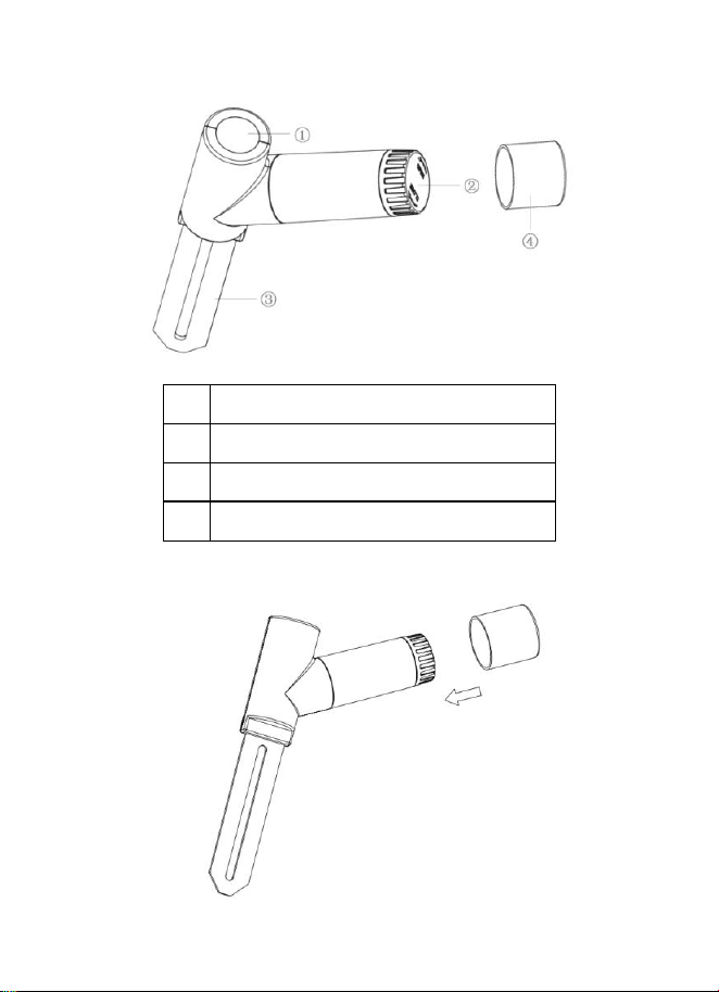
2.2 Soil Moisture Sensor Set Up
1. Open the battery cap of the soil moisture sensor
as shown in Figure 1
4
1
LED Indicator (RF transmission)
2
Battery Cap
3
Soil Moisture Sensor
4
Battery Door Protection Cover

5
Place the extra protection sensor cap over the
battery door to achieve better sealing against
moisture.
Figure 1
2. Insert one AA battery.
3. After inserting the battery, the remote sensor
LED indicator will light for 4 seconds, and then
flash once per 70 second thereafter. Each time it
flashes, the sensor is transmitting data.
4. Close the battery cap.
5. Insert the sensor totally into the soil of your
potted plant.
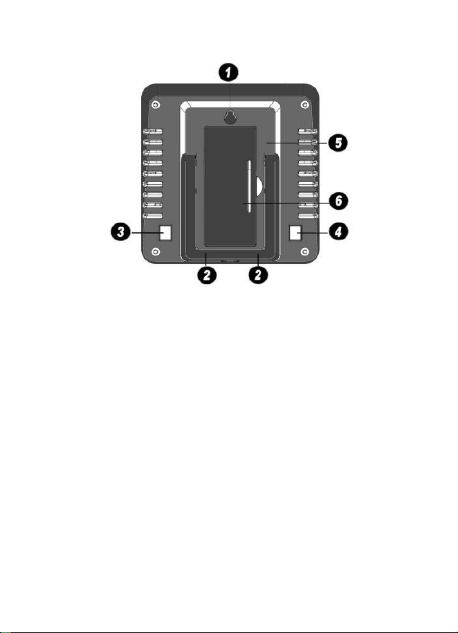
2.3 Display Console Set Up
1. Remove the battery door on the back of the
display, as shown in Figure 2. Insert one AA
(alkaline, lithium or rechargeable) battery in the
back of the display console.
6
Figure 2
1. Integrated Hanging Hole
2. Tabletop Stand
3. ADD+ Button
4. Set Button
5. Battery Compartment
6. Battery Compartment Cover
All of the LCD segments will light up for a few
seconds to verify all segments are operating
properly.
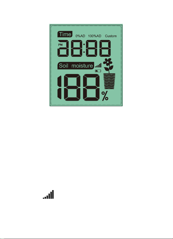
7
Full Display
2. Replace the battery door and fold out the desk
stand and place the console in the upright
position.
The console will instantly display the default
time (12:00). The soil moisture value will
update on the display within a few minutes.
While in the search mode, the reception search
icon flash.
If the remote does not update, please contact our
Customer Service for support.
8
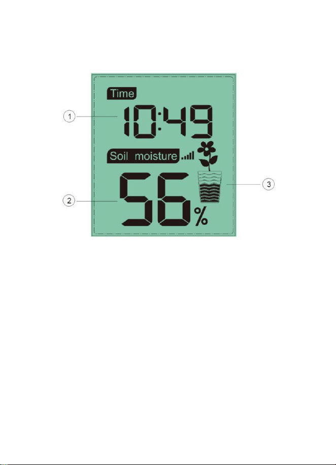
2.3.1 Display Console Layout
Figure 3
1. Time Display
2. Soil Moisture Value Display
3.
Soil Moisture Grade Display

9
3. Console Operation
Note: The console has two program modes: Time
setting mode and Custom mode.
If no operation for 20s, display will return to normal
mode.
3.1 Time setting mode
Long press SET button to enter the time setting
mode:
a. Short press ADD+, choose between 12/24hr
display
b. Short press SET, step into Hour setting, Short
press ADD+ to adjust hour.
c. Short press SET, step into Minute setting, Short
press ADD+ to adjust minute.
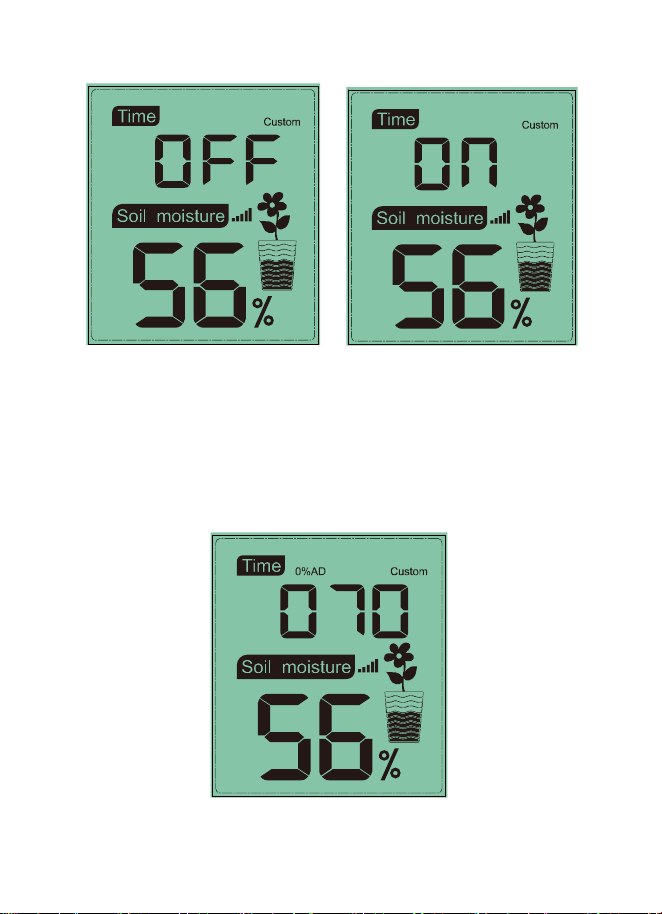
3.2 Custom mode
Custom OFF:
Moisture level is calculated based on default dry
and wet definition:
Dry (0%AD) AD: 70

10
Wet (100% AD) AD: 500
Soil Moisture = (moisture AD – 70) * 100% / ( 500 –
70 )
Example: when sensor moisture AD is 310,
calculated moisture is:
(310 – 70)*100% / (430) = 56%.
This is a fixed slope rate linear system.
Custom ON:
When pot soil at dry or wet condition is not giving
the moisture sensor output value that is close to its
default assumption, it will give inaccurate moisture
level results. It is commonly happening with different
soil type that gives very different output value at
same moisture level condition. We introduced this
custom mode to make this slope flexible so that it
can match your soil type.
This becomes a variable slope rate linear system.

11
Adjusting principle:
0%AD is used to adjust for dry condition reading
inconsistency.
When the displayed moisture readings are too high
at dry soil condition, you could lower the slope rate
by increasing the 0%AD value.
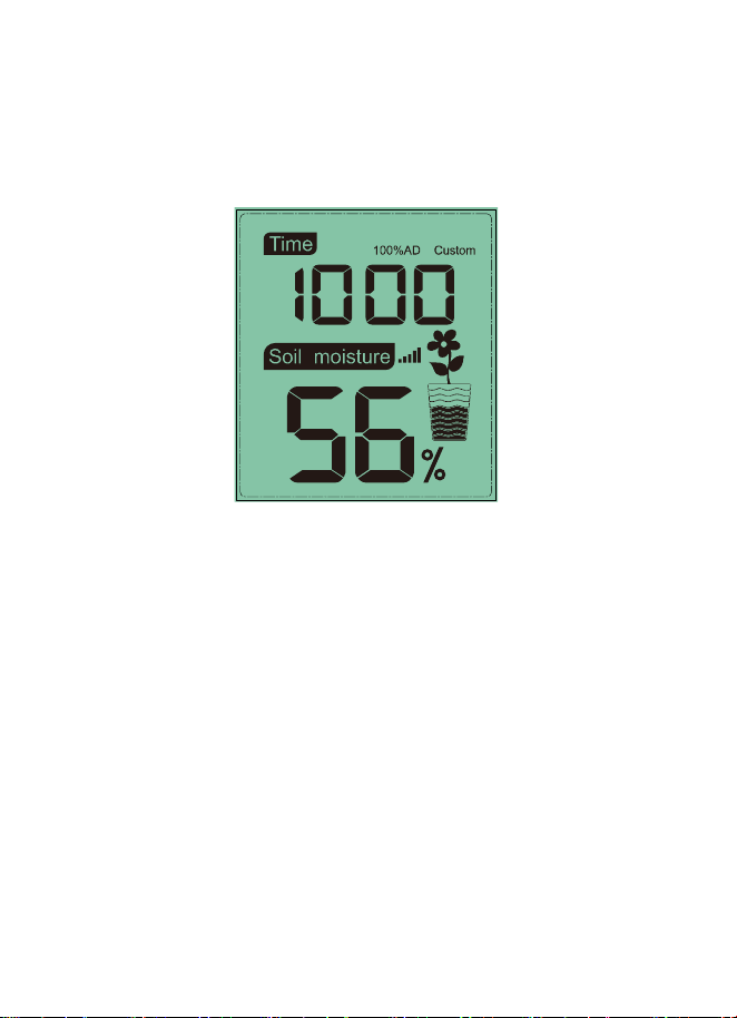
100%AD is used to adapt for wet condition reading
inconsistency.
When the displayed moisture readings are too low
at extremely wet soil condition, you could decrease
the 100%AD value to fix it.
Please refer to the below example for better
understanding.
For example:
When you use this product at the first time, please
turn off the custom mode and test the product at the
following two situations:

12
Situation One:
You watered your potted plant with enough water
and the soil should be extremely wet, however the
displayed moisture readings is much lower than
95%(e.g.70%).
Solution:
Enable custom mode, and enter 100%AD setting
mode.
Hold the ADD+ button, till the 100%AD value
reaches 1000 and roll over back to 80 ( if your
0%AD is 70 and not changed). Now the 100%AD
value will start from 80 while the displayed moisture
readings will be calculated to be 100%.
Hold the ADD+ button till the moisture readings start
to decrease until it shows 95%.
Record the 100%AD value for future use (when
batteries changed).
Situation Two:
Your potted plant hasn't been watered for very long
time and soil is extremely dry. When at this dry

13
condition, displayed moisture readings are much
higher than 10%(e.g.40%).
Solution:
Enable the custom mode and enter 0%AD setting
mode.
Hold the ADD+ button till the moisture readings
lowers to 10%(±).
Record the 0%AD value for future use (when
batteries changed).
Note: The soil moisture sensor should be inserted
totally into the soil for accurate result.
Operation Steps:
Short press SET after the time setting finished to
select “Custom ON” and it will enter the custom
setting mode:
a. Short press ADD+ , enable/disable the custom
function
14
b. If enable the custom function, short press ADD+
to adjust the 0%AD value from 70-200. The
numbers will change rapidly when hold the ADD+
button.
15
c. Short press SET to enter 100%AD setting mode.
short press ADD+ to adjust the 100%AD value
from 0%AD+10 ~ 1000.
d. Short press SET to return to the normal mode.
There is no “-“ button available on this item. If you
need to enter a value that is less than the value
display, you need to keep press the “+” button
until a rollover happens.
Important Note:
When adjusting, you should look at the displayed
moisture readings change. Stop immediately when
the expected moisture readings is displayed. If you
keep pressing the button and the setting value will

16
be increased beyond its sensing sensitive range,
resulting in making the system much less sensitive.
When this happens, please turn off the custom
mode and start over the custom calibration
procedure.
4. Function
1) 12/24hr digital time display
2) Current soil moisture.
3) Every 70 second the unit will receive soil
moisture sensor.
4) Wireless Signal Strength Indicator
During the synchronization, it will reduce one
signal segment if it have not received the signal
once from the transmitter. It will increase one
signal segment if it has received the signal
once.
Received the signal
once
Lost the signal

17
5. Appendix
Moisture grades display on the flower pot icon:
Humidity range: 4%~0%:Display 0 grid moisture
Humidity range: 14%~5%:Display 1 grid moisture
Humidity range: 24%~15%:Display 2 grids moisture
Humidity range: 34%~25%:Display 3 grids moisture
Humidity range: 44%~35%:Display 4 grids moisture
Humidity range: 54%~45%:Display 5 grids moisture
Humidity range: 64%~55%:Display 6 grids moisture
Humidity range: 74%~65%:Display 7 grids moisture
Humidity range: 84%~75%:Display 8 grids moisture
Humidity range: 94%~85%:Display 9 grids moisture
Humidity range: 100%~95%:Display 10 grids moisture
6. Specifications
Moisture Range:0~100%; Resolution:1%
0%AD setting range:70~200; Initial value:70
100%AD setting range:0%AD+10~1000; Initial
value:500
Frequency: 433 MHz

18
Update Rate: 70 seconds
Power Consumption: MIN 1Year battery life.
Base station (display console) : 1 x AA
battery(not included)
Remote sensor : 1 x AA battery(not included)
7. FCC Statement
Statement according to FCC part 15.19:
This device complies with part 15 of the FCC rules.
Operation is subject to the following two conditions:
1.This device may not cause harmful interference.
2.This device must accept any interference received,
including interference that may cause undesired
operation.
Statement according to FCC part 15.21:
Any changes or Modifications not expressly
approved by this company could void the user's
authority to operate the equipment.

19
Statement according to FCC part 15.105:
Note: This equipment has been tested and found to
comply with the limits for a Class B digital device,
pursuant to Part 15 of the FCC Rules. These limits
are designed to provide reasonable protection
against harmful interference in a residential
installation. This equipment generates, uses and
can radiate radio frequency energy and, if not
installed and used in accordance with the
instructions, may cause harmful interference to
radio communications.
However, there is no guarantee that interference will
not occur in a particular installation. If this
equipment does cause harmful interference to radio
or television reception, which can be determined by
turning the equipment off and on, the user is
encouraged to try to correct the interference by one
or more of the following measures:
• Reorient or relocate the receiving antenna.
• Increase the separation between the equipment
and receiver.
• Connect the equipment into an outlet on a circuit

20
different from that to which the receiver is
connected.
• Consult the dealer or an experienced radio/TV
technician for help.
This device complies with FCC radiation exposure
limits set forth for an uncontrolled environment and
it also complies with Part 15 of the FCC RF Rules.
This equipment must be installed and operated in
accordance with provided instructions
and the antenna(s) used for this
transmitter must be installed to provide
a separation distance of at least 20 cm from all
persons and must not be co-located or operating in
conjunction with any other antenna or transmitter.
End-users and installers must be provided with
antenna installation instructions and consider
removing the no-collocation statement.

21
8. Warranty Information
We disclaim any responsibility for any technical
error or printing error, or their consequences.
All trademarks and patents are recognized.
We provide a 1-year limited warranty on this product
against manufacturing defects in materials and
workmanship.
This limited warranty begins on the original date of
purchase, is valid only on products purchased and
only to the original purchaser of this product. To
receive warranty service, the purchaser must
contact us for problem determination and service
procedures.
This warranty covers only actual defects within the
product itself, and does not cover the cost of
installation or removal from a fixed installation,
normal set-up or adjustments, claims based on
misrepresentation by the seller or performance
variations resulting from installation-related
circumstances.
