1
Installation Guide
AT-GAIN-M50-LZ
50 Watt Mixer Amplier
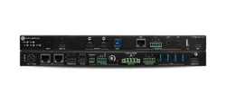
AT-GAIN-M50-LZ
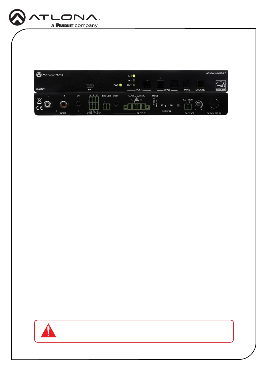
The Atlona AT-GAIN-M50-LZ is a two-input mixer amplier designed for low impedance
education and commercial applications. The amplier delivers either two channels of 25
watts each into 4 or 8 ohms, or a single channel of 50 watts. The GAIN-M50-LZ features two
unbalanced stereo audio inputs on RCA and 3.5 mm connections with independent level control
for each. An unbalanced 3.5 mm output allows the mixed signal to be passed to an assistive
listening system or separate amplier.
The GAIN-M50-LZ includes unique capabilities intended for education applications. Ducking
automatically lowers the program audio level on input 1 when a teacher speaks into a
microphone system connected to the unbalanced input 2. PA sense mutes the output of the
amplier whenever it detects activity on the school public address system. Both features ensure
important lesson material and announcements are heard clearly.
The compact, plenum rated enclosure allows the amplier to be mounted in a variety of locations
such as under a desk or table, on the wall behind a display, or in the ceiling.
The amplier includes an RS-232 port for automated operation from Velocity™ or third-party
control systems. It also supports remote volume control from the optional AT-GAIN-VOL
wallplate.
1 x AT-GAIN-M50-LZ
2 x 2-pin captive screw connectors
2 x 3-pin captive screw connectors
1 x 4-pin captive screw connector
4 x Machine screws
4 x Rubber feet
2 x Mounting brackets
1 x 24 V / 3 A power supply
1 x AC power cord
1 x Insert w/ QR code
Package Contents
IMPORTANT: Visit https://www.atlona.com/product/at-gain-m50-lz for
the latest rmware updates and User Manual.
2
Installation Guide
AT-GAIN-M50-LZ
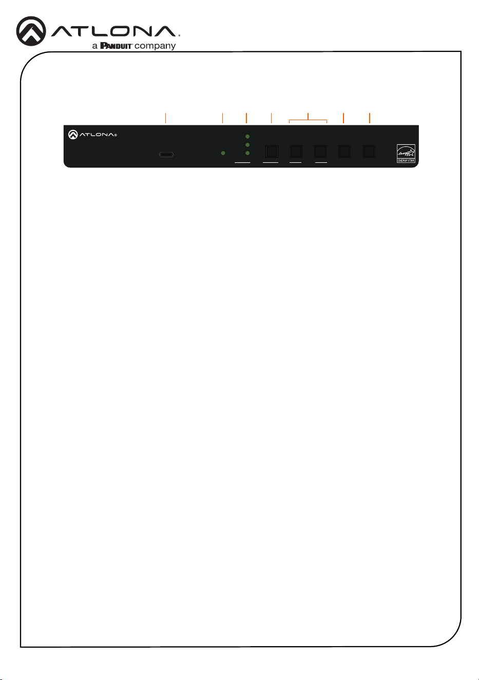
1 FW
Connect a USB-C cable to this port to
perform rmware updates. Refer to
Updating the Firmware (page 16) for
more information.
2 PWR
LED will be green when the AT-GAIN-
M50-LZ is powered.
3 IN 1, IN 2, OUT
LED will be green when set to the selected
input or output.
4 PORT button
Press this button to select the desired
port. Once the port is selected, the port
volume can be adjusted.
5 LEVEL
Press these buttons to increase (+) or
decrease (-) the audio output volume.
6 MUTE
Press this button to mute the audio
output.
7 DUCKING
Press this button to activate the audio
ducking feature.
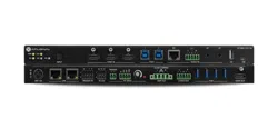
Front Panel Descriptions
1 2 3 4 6 75
PWR
IN 1
IN 2
OUT
FW PORT
LEVEL MUTE
DUCKING
AT-GAIN-M50-LZ
GAIN
TM
-
+
INPUT OUTPUT 3ADC 24V
RX TX
CTRL / RS-232
V
C
L R
1 2
-
+
TRIGGER MODE
STEREO
MONO
PA SENSE
CLASS 2 WIRING
L R
- -
+ +
LOOP
4Ω
8Ω
SPEAKER
+
-
25V-100V
+
-
3
Installation Guide
AT-GAIN-M50-LZ
PWR
IN 1
IN 2
OUT
FW PORT
LEVEL MUTE
DUCKING
AT-GAIN-M50-LZ
GAIN
TM
-
+
INPUT
OUTPUT 3ADC 24V
RX TX
CTRL / RS-232
V
C
L R
1 2
-
+
TRIGGER
MODE
STEREO
MONO
PA SENSE
CLASS 2 WIRING
L R
- -
+ +
LOOP
4Ω
8Ω
SPEAKER
+
-
25V-100V
+
-
Rear Panel Descriptions
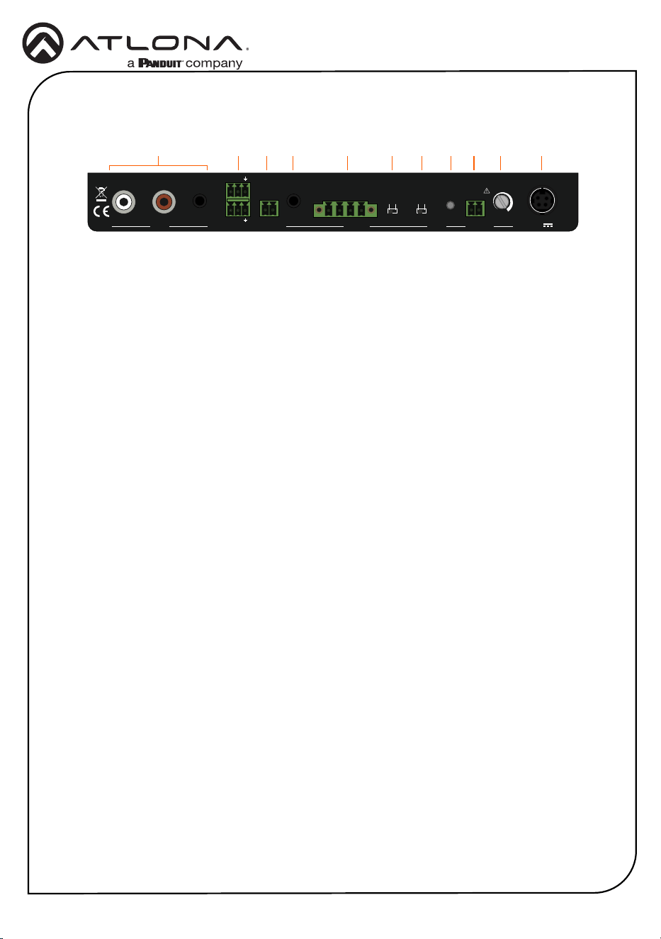
1 INPUT
Connect stereo RCA cables to INPUT 1
and/or connect a 3.5 mm stereo cable to
INPUT 2.
2 CTRL / RS-232
Connect the included 3-pin captive
screw connectors to these ports. The
top port is used for volume control, and
the bottom port is used to connect to a
control system. Both ports can be used
simultaneously.
3 TRIGGER
Connect one of the included 2-pin captive
screw connector to this port. Supports
audio mute with contact closure or PA
sense so announcements can be heard
clearly.
4 LOOP
Connect a 3.5 mm stereo cable from this
port to an assistive Listening System.
This port can also be used to daisy-chain
another amplier to the AT-GAIN-M50-LZ.
5 OUTPUT
Connect the included 4-pin captive screw
connector from this port to a pair of
program / stereo speakers. Supports 2 x
25 watts @ 4/8 ohms amplier (stereo or
dual mono) or 1 x 50 watts @ 4/8 ohms
(bridged).
6 MODE
Set this toggle switch to either STEREO
or MONO, based on the speaker
conguration of the OUTPUT port, above.
7 SPEAKER
Set this toggle switch to the correct
speaker impedance.
8 PA SENSE LED
This LED will be green when PA Sense is
active.
9 25V-100V (PA SENSE)
Connect one of the included 2-pin captive
screw connector from this port to a PA
speaker system.
10 Potentiometer (PA SENSE)
Adjusts the trigger voltage sensitivity.
11 DC 24V / 3A
Connect the included 24 V / 3 A power
supply from this port to an available AC
electrical outlet.
2 3 4 5 6 7 98 10 111
4
Installation Guide
AT-GAIN-M50-LZ
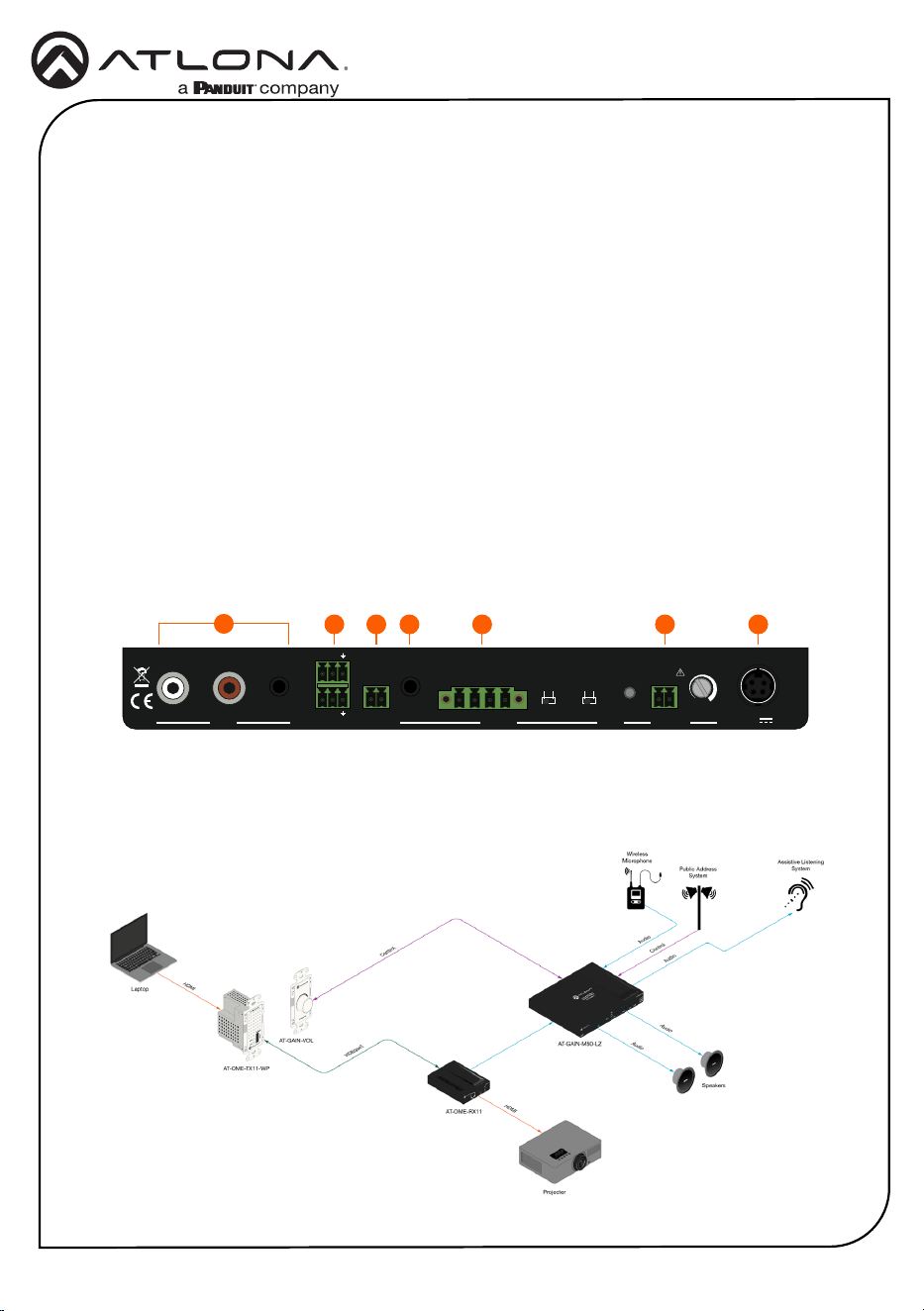
1. Connect stereo RCA cables to INPUT 1 and/or connect a 3.5 mm stereo cable to INPUT 2.
2. Connect the included 4-pin captive screw connector from the OUTPUT port to a pair of
program / stereo speakers. This port supports 2 x 25 watts @ 4/8 ohms (stereo or dual
mono) or 1 x 50 watts @ 4/8 ohms (bridged). Refer to Amplier Modes (page 7) for more
information.
3. Connect one of the included 2-pin captive screw connector from the PA SENSE port to a
PA speaker system. Refer to PA Sense (page 8) for more information.
4. Connect one of the included 2-pin captive screw connector from the TRIGGER port to a
paging sensor.
5. Connect the included 3-pin captive screw connectors to these ports. The top port is used
for volume control, and the bottom port is used to connect to a control system. Both ports
can be used simultaneously.
6. Connect a 3.5 mm stereo cable from this port to an assistive Listening System. This port
can also be used to daisy-chain another amplier to the AT-GAIN-M50-LZ.
7. Connect the included power supply to the DC 24V / 3A receptacle. Connect the AC power
cord to an available wall outlet.
Installation
1
PWR
IN 1
IN 2
OUT
FW PORT
LEVEL MUTE
DUCKING
AT-GAIN-M50-LZ
GAIN
TM
-
+
INPUT
OUTPUT 3ADC 24V
RX TX
CTRL / RS-232
V
C
L R
1 2
-
+
TRIGGER
MODE
STEREO
MONO
PA SENSE
CLASS 2 WIRING
L R
- -
+ +
LOOP
4Ω
8Ω
SPEAKER
+
-
25V-100V
+
-
2 345 6 7
Wiring Diagram
5
Installation Guide
AT-GAIN-M50-LZ
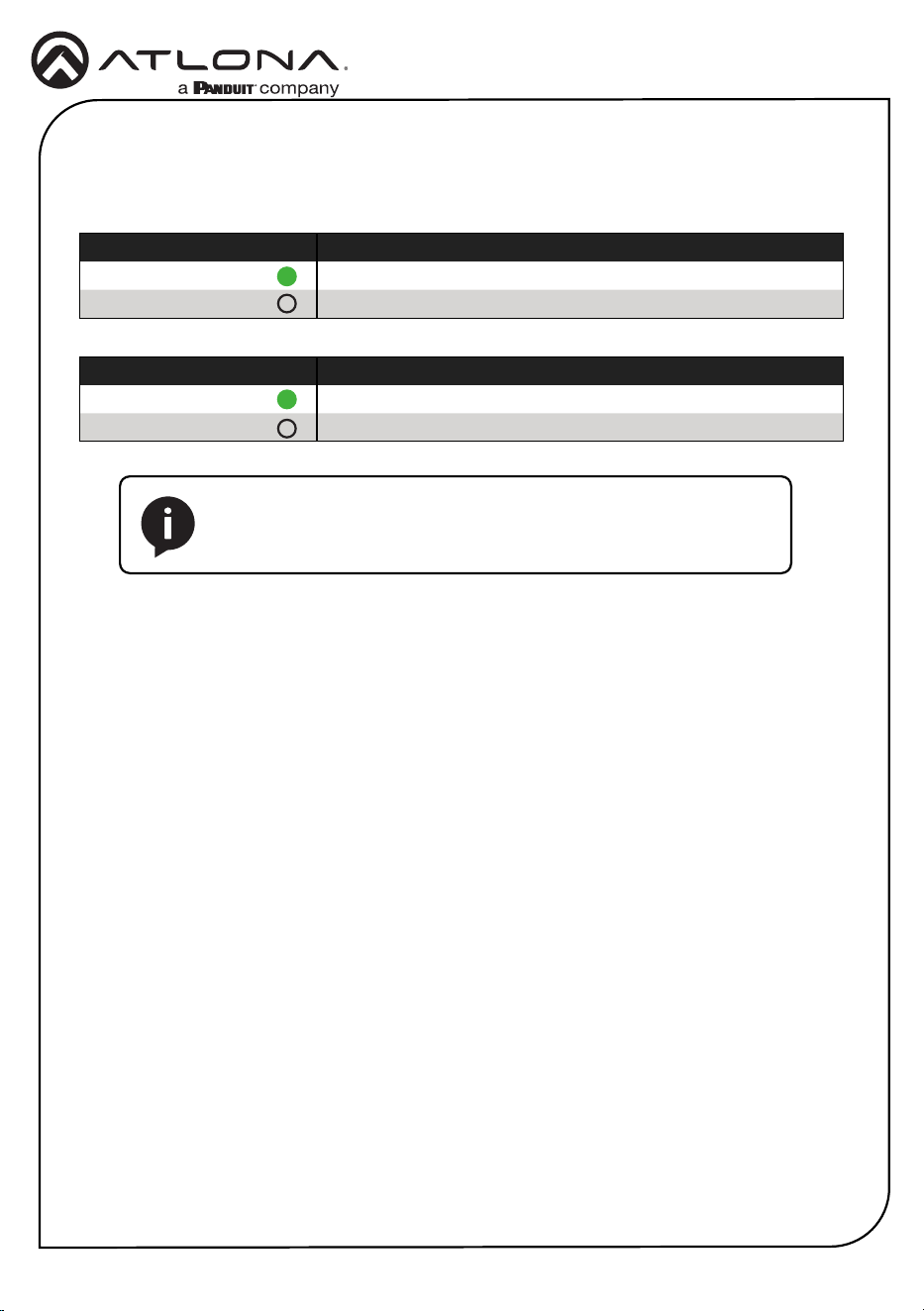
Front Panel LED Indicators
The LED indicators on both the front and rear of the unit provide basic information on the current
status of the unit.
PWR Description
Solid green Unit is powered.
O Unit is not powered.
IN 1, IN 2, OUT Description
Solid green Identies the currently selected port.
O The port is not selected.
NOTE: When all LED indicators are ashing, this means that the unit
is being reset to factory defaults. Refer to Performing a Factory Reset
(page 13) for more information.
6
Installation Guide
AT-GAIN-M50-LZ
The AT-GAIN-M50-LZ provides two standby modes: Eco and Net. By default, the unit is shipped
with Eco enabled, which complies with ENERGY STAR
®
and ErP regulations. To change the
standby mode to Network Standby, execute the StbyMode command over RS-232. Refer to the
AT-GAIN-M50-LZ API for a full list of commands.
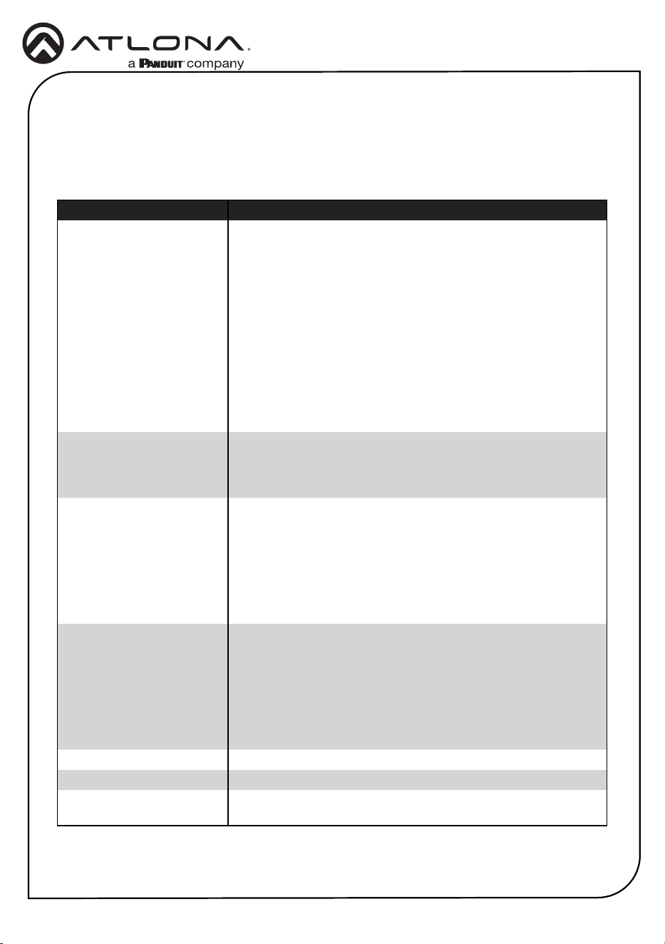
Command Description
StbyMode X
Sets the standby mode to be used, where X = {Eco, Net, sta}.
• Eco (DEFAULT) - This low-power mode consumes 0.5
watts, which complies with ERP regulations. The unit will
automatically go into this standby mode after the
APwrOTime timer has elapsed. To turn the unit back on,
press any press any button on the front panel or send the
PWON command using RS-232.
• Net - This low-power mode consumes approximately 2.2
watts. The unit will automatically go into this standby mode
after the APwrOTime timer has elapsed. To turn the unit
back on, play audio through the system, press any button
on the front panel, or send the PWON command using RS-
232.
STNDBY
Places the unit into low power mode. This low-power mode
consumes 0.5 watts, which complies with ERP regulations.
To turn the unit back on, press any button on the front panel or
send the PWON command using RS-232.
PWOFF
Executing this command will turn o the AT-GAIN-M50-LZ
according to the standby mode set by the StbyMode command.
Use the PWON command to turn on the AT-GAIN-M50-LZ.
• If StbyMode is set to Eco, sending the PWOFF command
will place the unit in Eco standby mode.
• If StbyMode is set to Net, sending the PWOFF command
will place the unit in Net standby mode.
PWON
Executing this command will turn on the AT-GAIN-M50-LZ
according to the standby mode set by the StbyMode command.
Use the PWOFF command to turn o the AT-GAIN-M50-LZ.
• If StbyMode is set to Eco, sending the PWON command will
turn on the AT-GAIN-M50-LZ from the Eco standby mode.
• If StbyMode is set to Net, sending the PWON command will
turn on the AT-GAIN-M50-LZ from the Net standby mode.
PWCTRL on
DEFAULT - Enables automatic standby functionality.
PWCTRL o
Disables automatic standby functionality.
APwrOTime
DEFAULT (15 minutes) - Sets the duration of inactivity required
before the device enters either Eco or Net standby mode.
Standby Modes
7
Installation Guide
AT-GAIN-M50-LZ
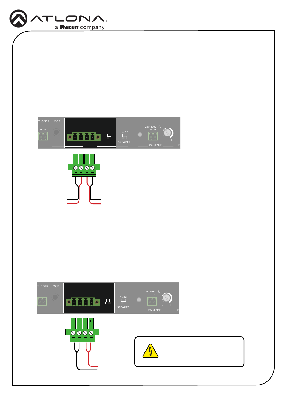
Amplier Modes
In stereo mode, the output delivers 25 watts per left and right channel. Stereo sources will pass
through to the amplier, unchanged.
In bridged mono mode, the output delivers 50 watts on a single channel. Stereo sources will be
summed to mono at the amplier.
Stereo Mode
Bridged Mono Mode
1. Locate the included 4-pin captive screw connector, for the OUTPUT port.
2. Connect the wires from the amplier to the port as shown below.
3. Set the MODE switch to STEREO.
1. Locate the included 4-pin captive screw connector, for the OUTPUT port.
2. Connect the wires from the amplier to the port as shown below.
3. Set the MODE switch to MONO.
PWR
IN 1
IN 2
OUT
FW PORT
LEVEL MUTE
DUCKING
AT-GAIN-M50-LZ
GAIN
TM
-
+
INPUT
OUTPUT
3ADC 24V
RX TX
CTRL / RS-232
V
C
L R
1 2
-
+
TRIGGER
MODE
STEREO
MONO
PA SENSE
CLASS 2 WIRING
L R
- -
+ +
LOOP
4Ω
8Ω
SPEAKER
+
-
25V-100V
+
-
PWR
IN 1
IN 2
OUT
FW PORT
LEVEL MUTE
DUCKING
AT-GAIN-M50-LZ
GAIN
TM
-
+
INPUT
OUTPUT
3ADC 24V
RX TX
CTRL / RS-232
V
C
L R
1 2
-
+
TRIGGER
MODE
STEREO
MONO
PA SENSE
CLASS 2 WIRING
L R
- -
+ +
LOOP
4Ω
8Ω
SPEAKER
+
-
25V-100V
+
-
Right ChannelLeft Channel
}
}
--
++
PWR
IN 1
IN 2
OUT
FW PORT
LEVEL MUTE
DUCKING
AT-GAIN-M50-LZ
GAIN
TM
-
+
INPUT
OUTPUT
3ADC 24V
RX TX
CTRL / RS-232
V
C
L R
1 2
-
+
TRIGGER
MODE
STEREO
MONO
PA SENSE
CLASS 2 WIRING
L R
- -
+ +
LOOP
4Ω
8Ω
SPEAKER
+
-
25V-100V
+
-
PWR
IN 1
IN 2
OUT
FW PORT
LEVEL MUTE
DUCKING
AT-GAIN-M50-LZ
GAIN
TM
-
+
INPUT
OUTPUT 3ADC 24V
RX TX
CTRL / RS-232
V
C
L R
1 2
-
+
TRIGGER
MODE
STEREO
MONO
PA SENSE
CLASS 2 WIRING
L R
- -
+ +
LOOP
4Ω
8Ω
SPEAKER
+
-
25V-100V
+
-
To speaker
}
R
L
WARNING: Risk of electrical
shock. Do not touch the
speaker output.
8
Installation Guide
AT-GAIN-M50-LZ
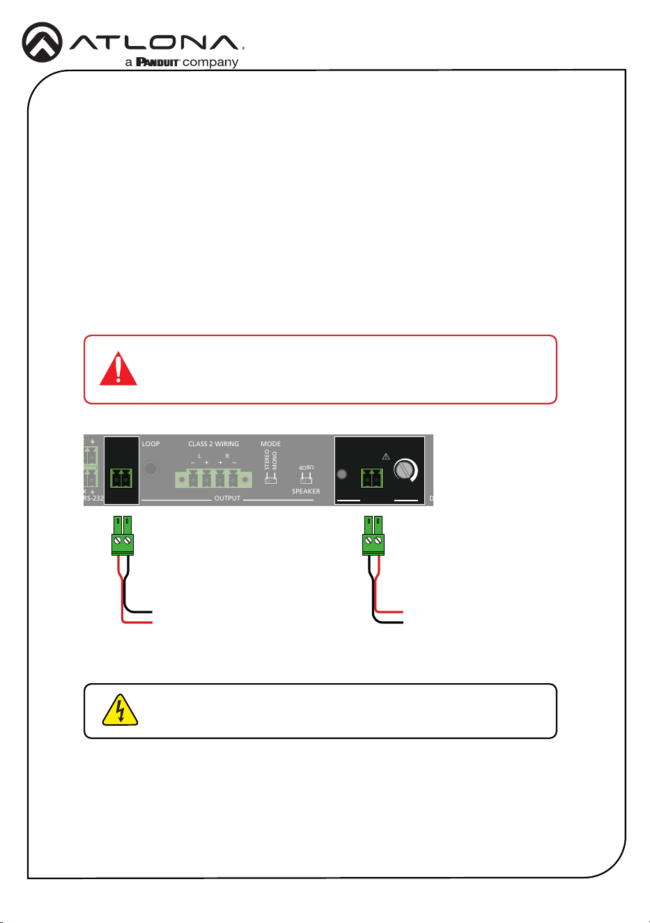
PA Sense
This section covers PA sense, which mutes the current audio program for the duration of a PA
broadcast. The default setting of this port is Normally Open (NO). This can be changed to
Normally Closed (NC) using the API.
1. Connect the PA SENSE port to the PA system and/or connect the TRIGGER port to the
paging sensor.
2. The PA SENSE LED indicator will light up when PA Sense is active.
3. Adjust the PA SENSE potentiometer until the LED remains continuously on. Then, rotate the
potentiometer until the LED turns o.
4. Test the PA system to verify PA Sense activation, and readjust the potentiometer if
necessary.
IMPORTANT: The AT-GAIN-M50-LZ supports 25 V to 100 V systems.
The wiring of the PA SENSE port must match the voltage rating of the
system’s amplier.
PWR
IN 1
IN 2
OUT
FW PORT
LEVEL MUTE
DUCKING
AT-GAIN-M50-LZ
GAIN
TM
-
+
INPUT
OUTPUT
3ADC 24V
RX TX
CTRL / RS-232
V
C
L R
1 2
-
+
TRIGGER
MODE
STEREO
MONO
PA SENSE
CLASS 2 WIRING
L R
- -
+ +
LOOP
4Ω
8Ω
SPEAKER
+
-
25V-100V
+
-
PWR
IN 1
IN 2
OUT
FW PORT
LEVEL MUTE
DUCKING
AT-GAIN-M50-LZ
GAIN
TM
-
+
INPUT OUTPUT 3ADC 24V
RX TX
CTRL / RS-232
V
C
L R
1 2
-
+
TRIGGER MODE
STEREO
MONO
PA SENSE
CLASS 2 WIRING
L R
- -
+ +
LOOP
4Ω
8Ω
SPEAKER
+
-
25V-100V
+
-
PWR
IN 1
IN 2
OUT
FW PORT
LEVEL MUTE
DUCKING
AT-GAIN-M50-LZ
GAIN
TM
-
+
INPUT OUTPUT 3ADC 24V
RX TX
CTRL / RS-232
V
C
L R
1 2
-
+
TRIGGER
MODE
STEREO
MONO
PA SENSE
CLASS 2 WIRING
L R
- -
+ +
LOOP
4Ω
8Ω
SPEAKER
+
-
25V-100V
+
-
To PA system
}
+
-
To paging sensor
}
-
+
WARNING: Risk of electrical shock. Do not touch the speaker
output.
9
Installation Guide
AT-GAIN-M50-LZ
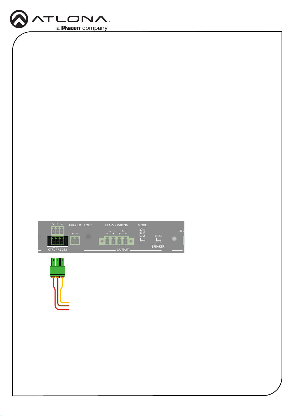
Control
The CTRL / RS-232 port provides both volume control and external control. The top port is
used to connect to the AT-GAIN-VOL (not included), and the bottom port is used to connect to a
control system. Both ports can be used simultaneously.
PWR
IN 1
IN 2
OUT
FW PORT
LEVEL MUTE
DUCKING
AT-GAIN-M50-LZ
GAIN
TM
-
+
INPUT
OUTPUT
3ADC 24V
RX TX
CTRL / RS-232
V
C
L R
1 2
-
+
TRIGGER
MODE
STEREO
MONO
PA SENSE
CLASS 2 WIRING
L R
- -
+ +
LOOP
4Ω
8Ω
SPEAKER
+
-
25V-100V
+
-
PWR
IN 1
IN 2
OUT
FW PORT
LEVEL MUTE
DUCKING
AT-GAIN-M50-LZ
GAIN
TM
-
+
INPUT OUTPUT 3ADC 24V
RX TX
CTRL / RS-232
V
C
L R
1 2
-
+
TRIGGER MODE
STEREO
MONO
PA SENSE
CLASS 2 WIRING
L R
- -
+ +
LOOP
4Ω
8Ω
SPEAKER
+
-
25V-100V
+
-
Volume Control
1. Connect one of the 3-pin captive screw connectors to the top port, using the wiring as
shown below.
2. Connect the opposite end to the 3-pin captive screw connector on the back of the
AT-GAIN-VOL.
GND
To AT-GAIN-VOL
}
C
V
10
Installation Guide
AT-GAIN-M50-LZ
PWR
IN 1
IN 2
OUT
FW PORT
LEVEL MUTE
DUCKING
AT-GAIN-M50-LZ
GAIN
TM
-
+
INPUT
OUTPUT
3ADC 24V
RX TX
CTRL / RS-232
V
C
L R
1 2
-
+
TRIGGER
MODE
STEREO
MONO
PA SENSE
CLASS 2 WIRING
L R
- -
+ +
LOOP
4Ω
8Ω
SPEAKER
+
-
25V-100V
+
-
PWR
IN 1
IN 2
OUT
FW PORT
LEVEL MUTE
DUCKING
AT-GAIN-M50-LZ
GAIN
TM
-
+
INPUT OUTPUT 3ADC 24V
RX TX
CTRL / RS-232
V
C
L R
1 2
-
+
TRIGGER MODE
STEREO
MONO
PA SENSE
CLASS 2 WIRING
L R
- -
+ +
LOOP
4Ω
8Ω
SPEAKER
+
-
25V-100V
+
-
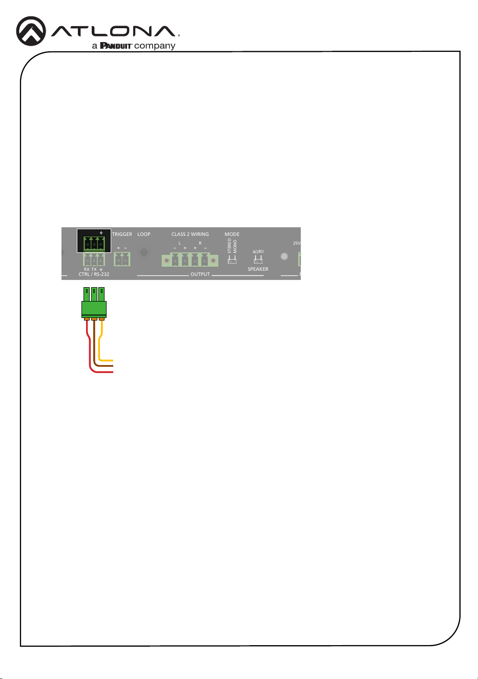
Connecting to a Control System
1. Connect an RS-232 cable, using a USB dongle, from the computer to the CTRL / RS-232
port on the AT-GAIN-M50-LZ.
2. Use a terminal client, such as Hercules, to establish a serial connection to the AT-GAIN-
M50-LZ.
3. The default baud rate settings for the AT-GAIN-M50-LZ are: 115200,N,8,1.
To change the baud rate settings, execute the Cspara command.
Example: Cspara[9600,8,0,1]
Refer to the AT-GAIN-M50-LZ API for a full list of commands.
4. Close the terminal session and disconnect the RS-232 cable between the computer and the
AT-GAIN-M50-LZ.
5. Connect one of the included 3-pin captive screw connectors to the bottom port and wire the
port as shown below.
6. Connect the opposite end to the control system.
GND
To control system
}
TX
RX
Before connecting to a control system, the AT-GAIN-M50-LZ may need to be congured over
RS-232.
11
Installation Guide
AT-GAIN-M50-LZ
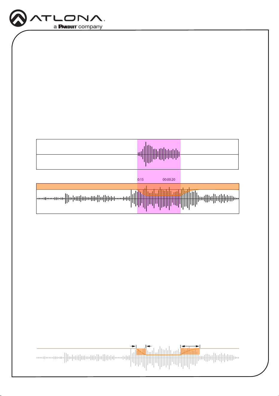
At 00:00:15, the background audio is automatically reduced to the level indicated by the shaded
area in orange. This reduction in volume of the background audio is performed through a
technique called sidechain compression, which uses the level of one audio channel to trigger a
compressor in order to control the volume level of another audio channel.
Ducking
Audio ducking is a technique where the volume of one sound (usually background music) is
automatically reduced when another sound (often a voice or main audio) is present. Ducking tem-
porarily “ducks”, or lowers, the volume level of one audio signal anytime a second audio signal is
present.
In Figure 1.1, two separate audio channels are shown: voice and background audio. The area
highlighted in purple, between 00:00:15 and approximately 00:00:22, indicates the time at which
the audio ducking takes place—that is, when the voice audio is present.
VOICE AUDIO
00:00:00 00:00:05 00:00:10 00:00:15 00:00:20 00:00:25 00:00:30
00:00:00 00:00:05 00:00:10 00:00:15 00:00:20 00:00:25 00:00:30
BACKGROUND AUDIO
Attack Release
Figure 1.1
Overview
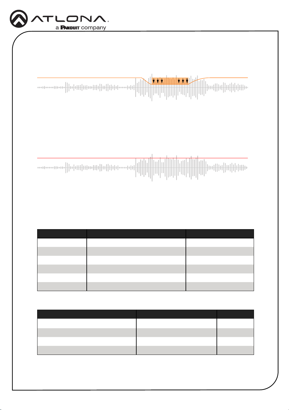
Settings
The AT-GAIN-M50-LZ oers four values for adjusting ducking performance. The shaded area in
orange, in Figure 1.1, will be examined to understand how these settings function.
Attack
The time, measured in milliseconds, required to reduce the audio track’s volume to the
designated ducking level (refer to Program Decrease on the next page).
Release
The time, in milliseconds, that it takes for the background audio to return to normal after the
voice audio signal stops.
12
Installation Guide
AT-GAIN-M50-LZ
Trigger
The audio trigger level, in decibels (dB). When this trigger level is exceeded, audio ducking is
activated, reducing the background audio channel volume. Once the audio level falls below this
threshold, the background audio channel returns to its normal volume.
Program Decrease
The maximum volume reduction in decibels (dB) that occurs when ducking is triggered.
This region lies between the attack and release phases.
Program Decrease
Ducking Trigger
The following presets are used by the AT-GAIN-M50-LZ. To adjust these values, changes must
be made using the MIC command. Refer to the AT-GAIN-M50-LZ API document for more
information.
Setting Preset Value Range
Attack (ms)
100 ms 1...1000
Release (ms)
1000 ms + 300 ms ramp 1...3000
Program Decrease (dB)
-20 dB -60...0
Trigger (dB)
-30 dB -60...0
Parameter Description Range
on
Enables microphone N/A
o
Disables microphone N/A
atime
Attack time (ms)
1...1000
rtime
Release time (ms)
1...3000
sens
Microphone sensitivity level (dB)
-60...0
reduce
Background noise reduction (dB)
-60...0
13
Installation Guide
AT-GAIN-M50-LZ
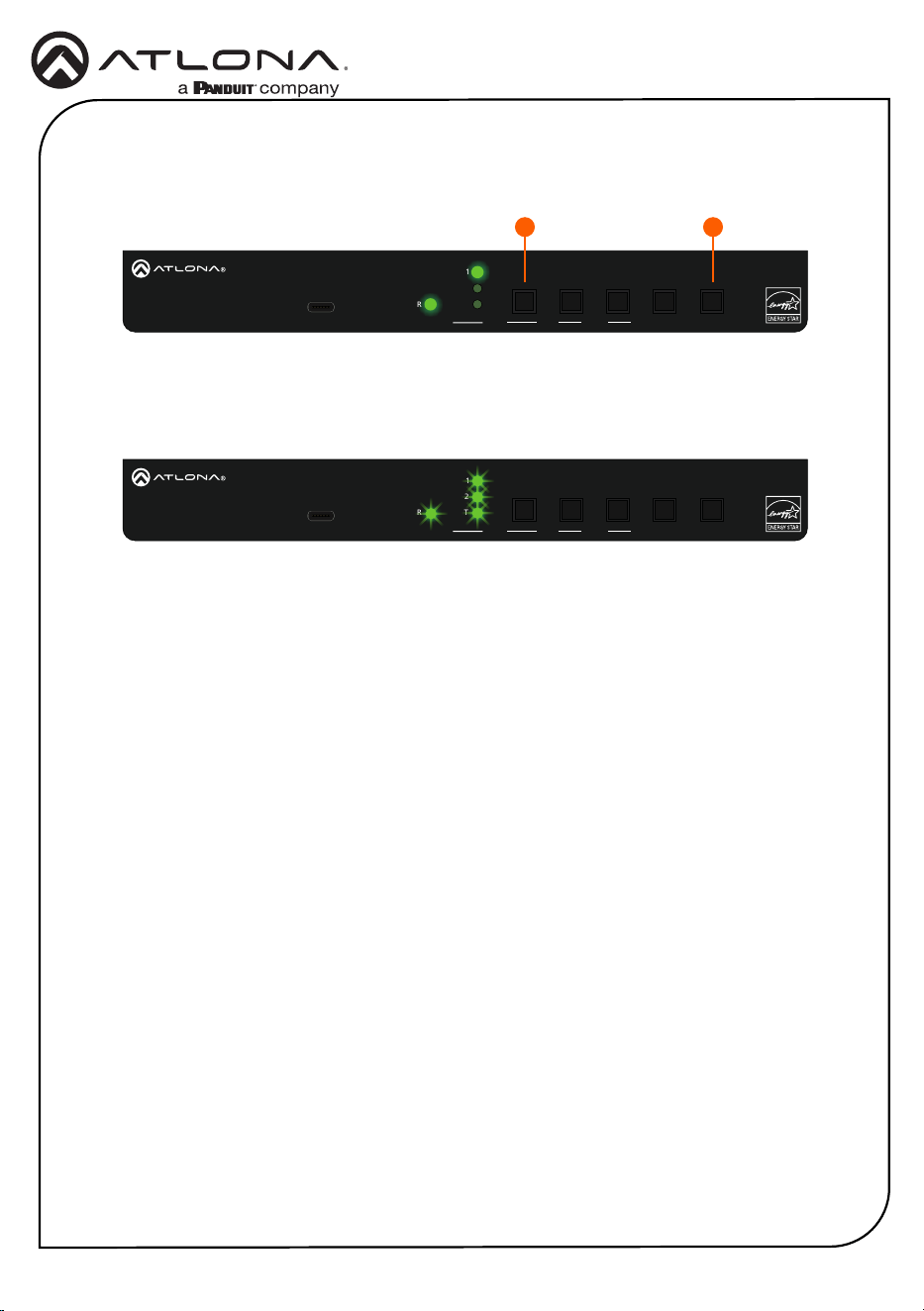
Performing a Factory Reset
1. Simultaneously press and hold both the PORT (1) and DUCKING (2) buttons for 10
seconds.
PWR
IN 1
IN 2
OUT
FW PORT
LEVEL MUTE
DUCKING
AT-GAIN-M50-LZ
GAIN
TM
-
+
INPUT OUTPUT 3ADC 24V
RX TX
CTRL / RS-232
V
C
L R
1 2
-
+
TRIGGER MODE
STEREO
MONO
PA SENSE
CLASS 2 WIRING
L R
- -
+ +
LOOP
4Ω
8Ω
SPEAKER
+
-
25V-100V
+
-
PWR
IN 1
IN 2
OUT
FW PORT
LEVEL MUTE
DUCKING
AT-GAIN-M50-LZ
GAIN
TM
-
+
INPUT OUTPUT 3ADC 24V
RX TX
CTRL / RS-232
V
C
L R
1 2
-
+
TRIGGER MODE
STEREO
MONO
PA SENSE
CLASS 2 WIRING
L R
- -
+ +
LOOP
4Ω
8Ω
SPEAKER
+
-
25V-100V
+
-
1 2
2. The LED indicators on the unit will ash to indicate the factory reset has occurred.
3. Release the PORT and DUCKING buttons when the LED indicators begin ashing.
14
Installation Guide
AT-GAIN-M50-LZ
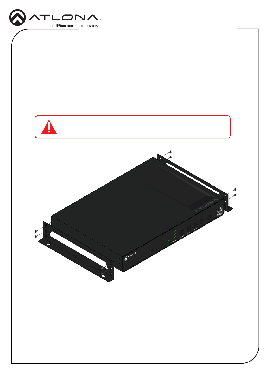
Mounting Instructions
The AT-GAIN-M50-LZ includes two mounting brackets and four mounting screws, which can be
used to attach the units to any at surface.
1. Locate the four screws included in the packaging and set them aside.
2. Using a Phillips screwdriver, remove the top two screws from one side of the AT-GAIN-M50-
LZ enclosure.
3. Align the mounting bracket with the side of the AT-GAIN-M50-LZ and fasten it using two
screws from the packaging along with the two previously removed enclosure screws.
AT-OME-SR21
OUTPUT
LAN DC 24VRELAY
C1 COM C2
HDBaseT IN
L R
+
+
1
IP MODE
RESET RS-232
1 2
RX RXTX TX
2
PWR
IN 1
IN 2
OUT
FW PORT
LEVEL MUTE
DUCKING
AT-GAIN-M50-LZ
GAIN
TM
-
+
4. Repeat steps 2 and 3 for the opposite side of the AT-GAIN-M50-LZ.
IMPORTANT: Avoid using high-torque tools on the machine screws,
as excessive force may damage the enclosure or strip the screws.
15
Installation Guide
AT-GAIN-M50-LZ
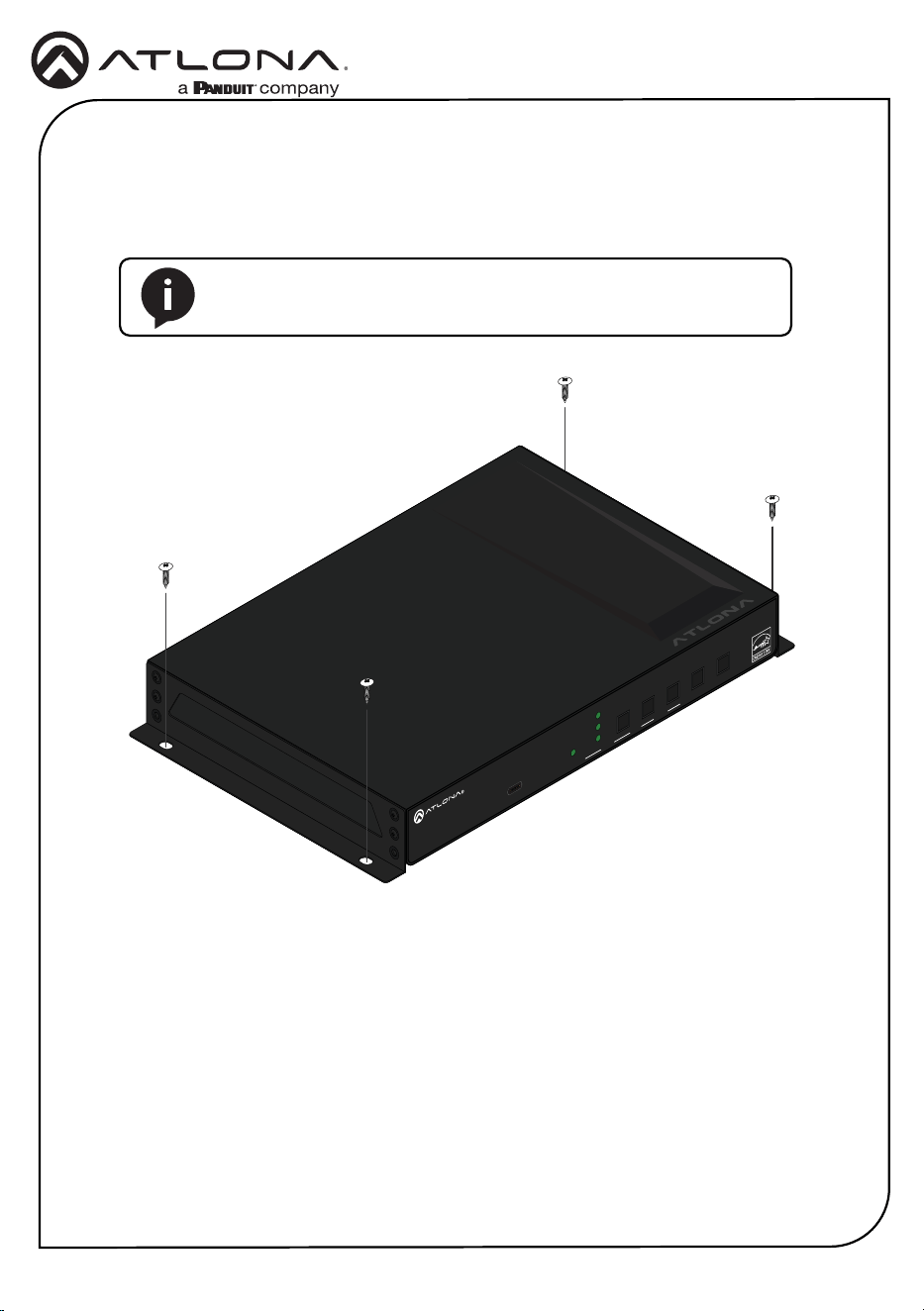
Mounting Instructions (continued)
5. Mount the unit using the oval-shaped holes, on each mounting bracket. If using a drywall
surface, a #6 drywall screw is recommended.
AT-OME-SR21
OUTPUT
LAN DC 24VRELAY
C1 COM C2
HDBaseT IN
L R
+
+
1
IP MODE
RESET RS-232
1 2
RX RXTX TX
2
PWR
IN 1
IN 2
OUT
FW PORT
LEVEL MUTE
DUCKING
AT-GAIN-M50-LZ
GAIN
TM
-
+
NOTE: Mounting brackets can also be inverted to mount the unit
under a table or other at surface.
16
Installation Guide
AT-GAIN-M50-LZ
Updating the Firmware
Requirements:
• AT-GAIN-M50-LZ
• Firmware le
• Computer running Windows
• USB-C cable
• USB Firmware Update Tool
1. Download the rmware le from atlona.com and extract the contents of the .zip le to a
folder on the computer desktop.
2. Disconnect power from the unit.
3. Connect the USB-C cable from the FW port on the AT-GAIN-M50-LZ to the computer.
USB-C to USB-C or USB-A to USB-C cables can be used.
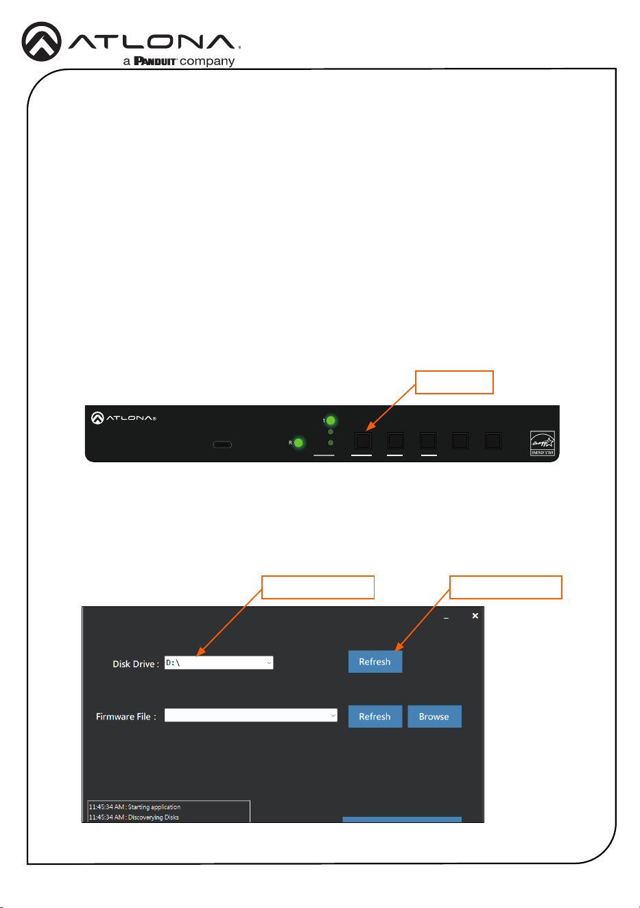
4. While pressing and holding the PORT (1) button, reconnect power to the AT-GAIN-M50-LZ.
5. If a USB UPDATE folder is opened automatically, notate the drive letter and close the folder.
6. Launch the USB Update Tool.
7. The drive letter of the mounted drive for the unit will be displayed in the Disk Drive eld.
If it is not, click the Refresh button.
Mounted drive letter
PWR
IN 1
IN 2
OUT
FW PORT
LEVEL MUTE
DUCKING
AT-GAIN-M50-LZ
GAIN
TM
-
+
INPUT OUTPUT 3ADC 24V
RX TX
CTRL / RS-232
V
C
L R
1 2
-
+
TRIGGER MODE
STEREO
MONO
PA SENSE
CLASS 2 WIRING
L R
- -
+ +
LOOP
4Ω
8Ω
SPEAKER
+
-
25V-100V
+
-
PORT button
Refresh button
17
Installation Guide
AT-GAIN-M50-LZ
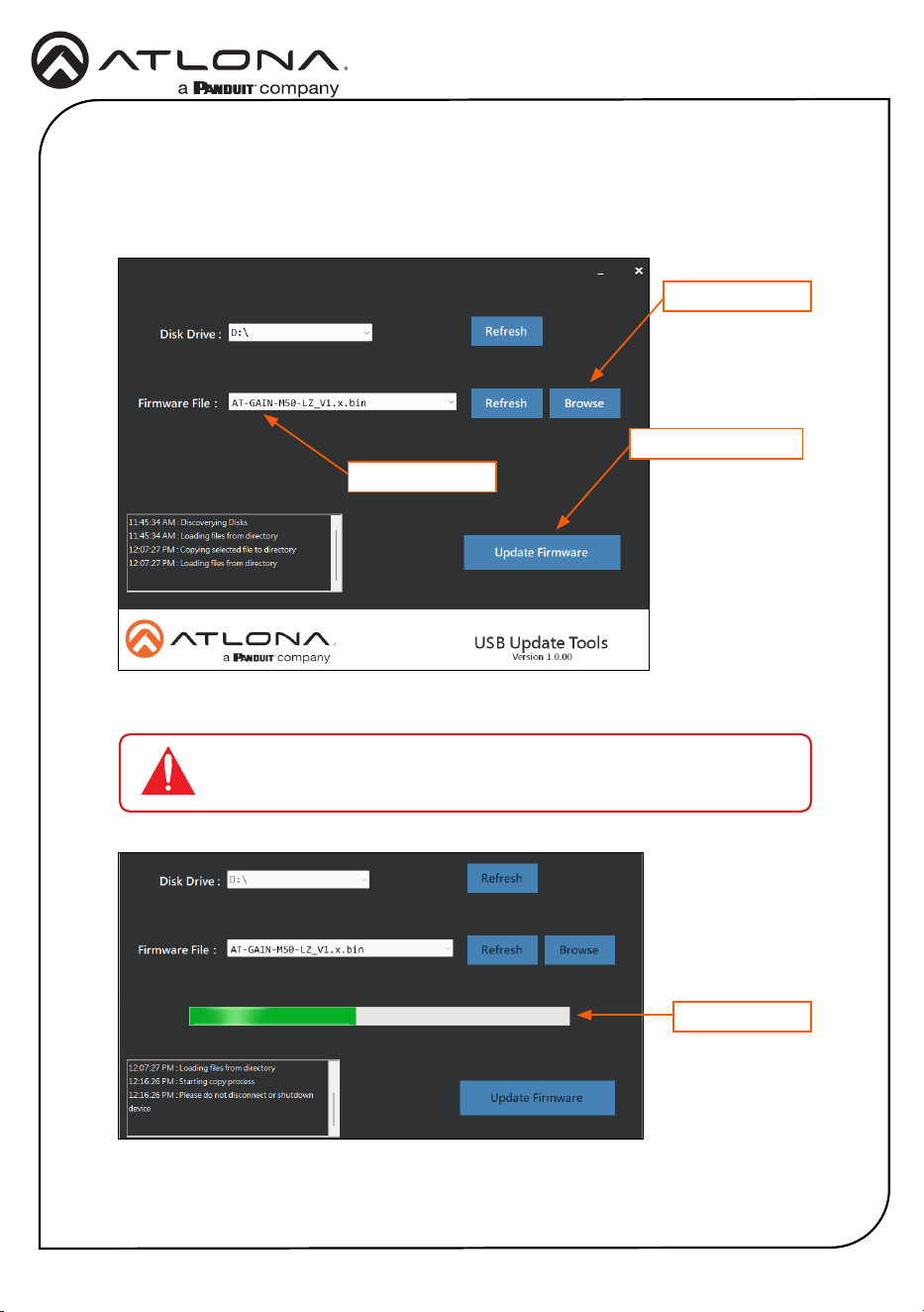
Firmware file
Browse button
Update Firmware button
IMPORTANT: Do not disconnect power from the unit while performing
the rmware update procedure.
Progress bar
8. Click the Browse button and select the rmware le. Once the rmware le is selected, it
will appear in the Firmware File eld. If the rmware le is not displayed in this eld, click
the Refresh button.
9. Click the Update Firmware button.
10. The rmware update process will begin and will be monitored by a progress bar.
18
Installation Guide
AT-GAIN-M50-LZ
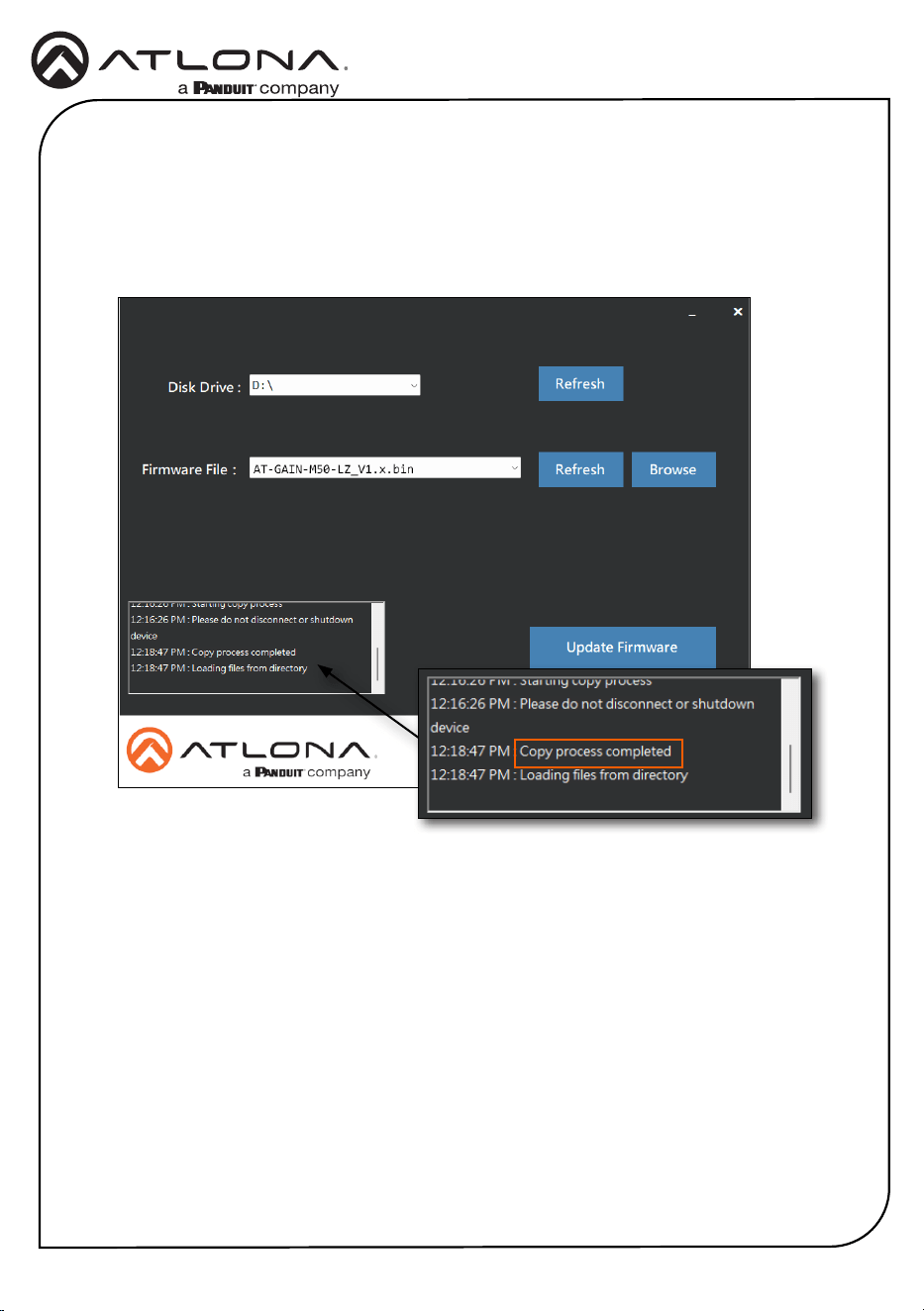
11. After the update process has completed, the Copy process completed message will be
displayed in the message window.
The PWR LED indicator, on the front panel, will ash green while the unit is being updated.
Do not disconnect the USB cable during the update process. When the PWR LED stops
ashing and is solid green, the update process will be complete.

19
Installation Guide
AT-GAIN-M50-LZ
Notes

20
Installation Guide
AT-GAIN-M50-LZ
Notes

21
Installation Guide
AT-GAIN-M50-LZ
25318-R4
© 2025 Atlona Inc. All rights reserved. “Atlona” and the Atlona logo are registered trademarks of Atlona Inc. All other brand names and trademarks or registered
trademarks are the property of their respective owners. Pricing, specications and availability subject to change without notice. Actual products, product images, and
online product images may vary from images shown here.
English Declaration of Conformity
The English version can be found under the resources tab at:
https://atlona.com/product/at-gain-m50-lz/.
Warranty
Chinese Declaration of Conformity 中国RoHS合格声明
To view the product warranty, use the following link or QR code:
https://atlona.com/warranty/.
由SKU列出於:
https://atlona.com/about-us/china-rohs/.
US International
atlona.com • 408.962.0515 • 41.43.508.4321