1
Installation Guide
AT-OME-CS31-SA
AV Presentation
and Collaboration System
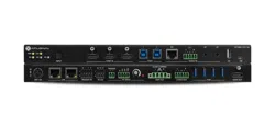
AT-OME-CS31-SA
The Atlona AT-OME-CS31-SA is an AV presentation and collaboration system for classrooms
and conference rooms. It features a 3x1 HDMI
®
switcher, 50 watt mixer amplier, and USB 3.0
hub.
The HDMI switcher is HDCP 2.2 compliant and supports up to 4K/60 4:4:4 plus HDR formats
for common inputs such as laptops, computers, and document cameras routed to the output
connected to a projector or display. The OME-CS31-SA amplier delivers either two channels
of 25 watts or a single channel of 50 watts into 4 or 8 ohms. It features one balanced stereo
audio input and two unbalanced stereo audio inputs with independent level control for each. A
balanced stereo line level output allows the mixed signal to be passed to an assistive listening
system or separate amplier. The OME-CS31-SA includes USB 3.0 interfaces for two host
computers, plus four peripheral devices such as a camera, speakerphone, interactive display,
keyboard, mouse, or storage device.
IMPORTANT: Visit https://www.atlona.com/product/at-ome-cs31-sa for the latest rm-
ware updates and User Manual.
1 x AT-OME-CS31-SA
1 x Envelope of mating connectors for all captive-screw connectors
1 x Surface mount brackets
4 x rubber feet
1 x 24 V / 5 A power supply
1 x AC cord
1 x Insert w/ QR code
Package Contents

2
Installation Guide
AT-OME-CS31-SA
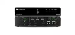
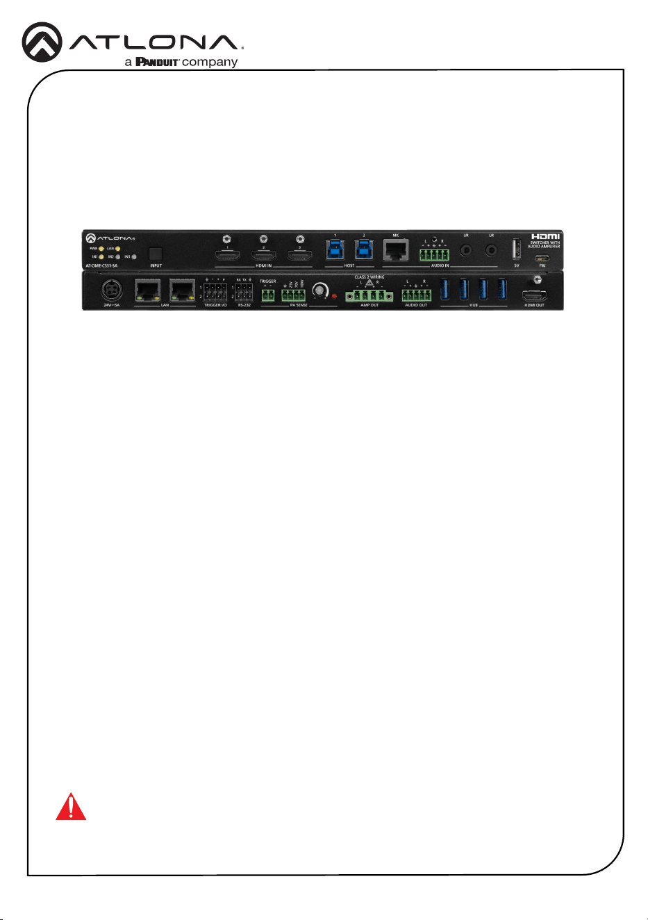
1 LED Indicators
Displays the current state of the unit:
PWR - LED will be red while the unit
is booting and green when operating
normally.
LAN - LED will be green when connected
to a switch or other LAN device.
IN1, IN2, IN3 - LED will be green when set
to the current input.
2 INPUT
Press and release this button to cycle
between each of the available inputs.
3 HDMI IN
Connect an HDMI cable from each of
these ports to an HDMI source.
4 HOST
Connect a USB cable from each of these
ports to a host USB device.
5 MIC
This port is for future use.
6 VOICE L/R
Connect the included 5-pin captive screw
connector from this port to a balanced
analog audio input.
7 L/R
Connect a music player, Bluetooth
™
receiver, or other unbalanced stereo
source to each of these 3.5 mm mini-
stereo ports.
8 5V
Provides +5 V USB power. Can be used
to attach Bluetooth
™
audio adapters or
powered USB hubs.
9 FW
This USB-C port is used to update the
rmware. Refer to the User Manual for
more information.
Front Panel Descriptions
1 2 3 4 5 6 7 8
9
HDMI OUTHUBAUDIO OUTAMP OUTPA SENSERS-232TRIGGER I/O
LAN
100V
70V
25V
CLASS 2 WIRING
TRIGGER R
RXP
1
2
1
2
TX
LRL
24V 5A
5V FWINPUTAT-OME-CS31-SA
PWR LAN
IN1
1 2 MIC
L R
L/R L/R
IN2
IN3
HDMI IN
HOST AUDIO IN
SWITCHER WITH
AUDIO AMPLIFIER

3
Installation Guide
AT-OME-CS31-SA
HDMI OUTHUBAUDIO OUTAMP OUTPA SENSERS-232TRIGGER I/O
LAN
100V
70V
25V
CLASS 2 WIRING
TRIGGER R
RXP
1
2
1
2
TX
LRL
24V 5A
5V FWINPUTAT-OME-CS31-SA
PWR LAN
IN1
1 2 MIC
L R
L/R L/R
IN2
IN3
HDMI IN HOST AUDIO IN
SWITCHER WITH
AUDIO AMPLIFIER
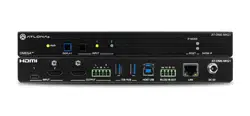
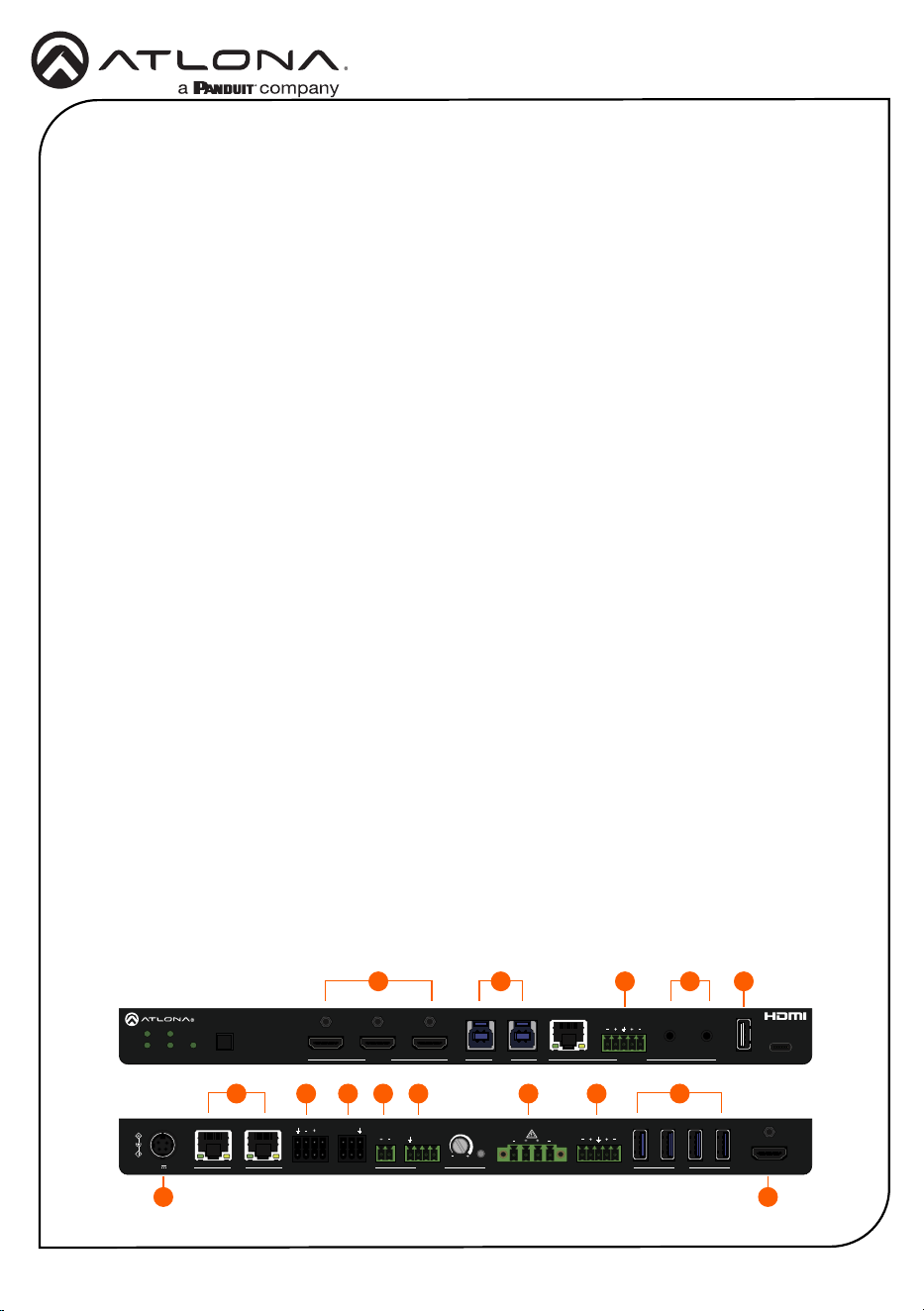
Rear Panel Descriptions
1 24V / 5A
Connect the included 24 V / 5 A power
supply from this port to an available AC
electrical outlet.
2 LAN
Connect an Ethernet cable from either of
these ports to the LAN. The other LAN
port can be used to connect an Ethernet
cable to a display or other device.
3 TRIGGER I/O
Connect the included double-stack 4-pin
connector to this port. This port consists
of two separate ports: TRIGGER I/O 1
(top) and TRIGGER I/O 2 (bottom).
4 RS-232
Connect the included double-stack 3-pin
captive screw connector to this port.
This port consists of two separate ports:
RS-232 1 (top) and RS-232 2 (bottom).
5 TRIGGER (PA SENSE)
Connect the included 2-pin captive screw
connector to this port. Supports audio
mute with contact closure or PA sense so
announcements can be heard clearly.
6 GND/25V/75V/100V (PA SENSE)
Connect the included 4-pin captive screw
connector from this port to a PA speaker
system.
7 Potentiometer (PA SENSE)
Adjusts the trigger voltage sensitivity.
8 AMP OUT
Connect the included 4-pin captive screw
connector from this port to a pair of
program / stereo speakers. Supports 2 x
25 watts @ 4/8 ohms amplier (stereo or
dual mono) or 1 x 50 watts @ 4/8 ohms
(bridged).
9 AUDIO OUT
Connect the included 5-pin captive screw
connector from this port to an assistive
listening device or additional amplier.
10 HUB
Connect up to 4 USB devices to these
ports.
11 HDMI OUT
Connect an HDMI cable from this port to
a display.
981 2 3 4 5 6 7 1110
4
Installation Guide
AT-OME-CS31-SA
HDMI OUTHUBAUDIO OUTAMP OUTPA SENSERS-232TRIGGER I/O
LAN
100V
70V
25V
CLASS 2 WIRING
TRIGGER R
RXP
1
2
1
2
TX
LRL
24V 5A
5V FWINPUTAT-OME-CS31-SA
PWR LAN
IN1
1 2 MIC
L R
L/R L/R
IN2
IN3
HDMI IN
HOST AUDIO IN
SWITCHER WITH
AUDIO AMPLIFIER
HDMI OUTHUBAUDIO OUTAMP OUTPA SENSERS-232TRIGGER I/O
LAN
100V
70V
25V
CLASS 2 WIRING
TRIGGER R
RXP
1
2
1
2
TX
LRL
24V 5A
5V FWINPUTAT-OME-CS31-SA
PWR LAN
IN1
1 2 MIC
L R
L/R L/R
IN2
IN3
HDMI IN HOST AUDIO IN
SWITCHER WITH
AUDIO AMPLIFIER
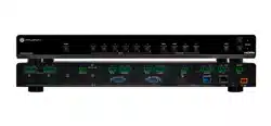
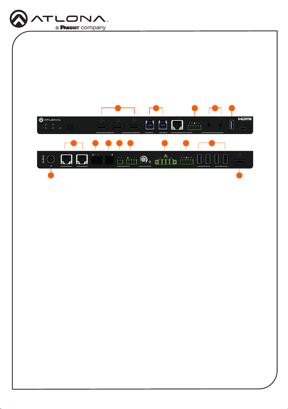
Installation
1. Connect an HDMI cable from a source to these HDMI IN ports.
2. Connect an HDMI cable from the HDMI OUT port to a local display.
3. Connect a USB cable from these HOST ports to a computer.
4. Connect an Ethernet cable from one of the LAN port to the Local Area Network (LAN).
This step will be required in order to access the built-in web server. Connect the other LAN
port to a display or other Ethernet device.
5. Connect the included 5-pin captive screw connector from the AUDIO IN port to source with
a balanced audio output. This port also has a chassis ground that is to be used if there is
any noise in the balanced signal.
6. Connect a music player, Bluetooth receiver, or other unbalanced stereo source to each of
these L/R 3.5 mm mini-stereo ports.
7 Connect a USB device that needs power to this port, such as a Bluetooth receiver, to the 5V
port.
8. Connect the included double-stacked 4-pin captive screw connector to this port. If only
a single port is being used, then connect the included single 4-pin captive screw. Two
TRIGGER I/O ports are provided: TRIGGER I/O 1 and TRIGGER I/O 2. These ports can
be used to control projection screens or other devices.
9. Connect the included double-stacked 3-pin captive screw connector to this port. If only a
single port is being used, then connect the included single 3-pin captive screw. Two RS-232
ports are provided: RS-232 1 and RS-232 2. These ports can be used for console and
display control.
10. Connect the included 2-pin captive screw connector from the TRIGGER (PA SENSE) port
to a re alarm system or other contact-closure input.
11. Connect the included 4-pin captive screw connector from the GND/25V/70V/100V port to
a PA speaker system. Make sure to connect the wires to the matching voltage of the PA
system.
12. Connect the included 4-pin captive screw connector from the AMP OUT port to a pair of
program / stereo speakers. Supports 2 x 25 watts @ 4/8 ohms amplier (stereo or dual
mono) or 1 x 50 watts @ 4/8 ohms (bridged).
1 3 6
4 14
8 9 10 11 12 13
75
215
5
Installation Guide
AT-OME-CS31-SA
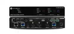
13. Connect the included 5-pin captive screw connector from the AUDIO OUT port to an
assistive listening device or additional amplier.
14. Connect up to 4 USB devices to these HUB ports.
15. Connect the included power supply from the 24V/5A port to an available AC electrical
outlet.
Installation (continued)
HDMI OUTHUBAUDIO OUTAMP OUTPA SENSERS-232TRIGGER I/O
LAN
100V
70V
25V
CLASS 2 WIRING
TRIGGER R
RXP
1
2
1
2
TX
LRL
24V 5A
5V FWINPUTAT-OME-CS31-SA
PWR LAN
IN1
1 2 MIC
L R
L/R L/R
IN2
IN3
HDMI IN
HOST AUDIO IN
SWITCHER WITH
AUDIO AMPLIFIER
HDMI OUTHUBAUDIO OUTAMP OUTPA SENSERS-232TRIGGER I/O
LAN
100V
70V
25V
CLASS 2 WIRING
TRIGGER R
RXP
1
2
1
2
TX
LRL
24V 5A
5V FWINPUTAT-OME-CS31-SA
PWR LAN
IN1
1 2 MIC
L R
L/R L/R
IN2
IN3
HDMI IN HOST AUDIO IN
SWITCHER WITH
AUDIO AMPLIFIER
1 3 6
4 14
8 9 10 11 12 13
75
215

6
Installation Guide
AT-OME-CS31-SA
Accessing the built-in Web Server
The AT-OME-CS31-SA includes a built-in web server, which allows easy management and
control of all features. Before using the web server, a password must be created.
1. Make sure that an Ethernet cable is connected between one of the LAN ports on the AT-
OME-CS31-SA and the network.
2. Launch a web browser and enter the IP address of the unit.
3. The Login page will be displayed.
4. Enter Atlona in the provided eld.
5. Click the Login button.
6. The Change Password screen will be displayed.
7. Enter the desired password in the Admin Password eld.
8. Click the Save button.

7
Installation Guide
AT-OME-CS31-SA
25353-R1
®
The terms HDMI, HDMI High-Denition Multimedia Interface, HDMI trade dress and the HDMI Logos are
trademarks or registered trademarks of HDMI Licensing Administrator, Inc.
© 2024 Atlona Inc. All rights reserved. “Atlona” and the Atlona logo are registered trademarks of Atlona Inc. All other brand names and trademarks or registered
trademarks are the property of their respective owners. Pricing, specications and availability subject to change without notice. Actual products, product images, and
online product images may vary from images shown here.
English Declaration of Conformity
The English version can be found under the resources tab at:
https://atlona.com/product/at-ome-cs31-sa/.
Warranty
Chinese Declaration of Conformity 中国RoHS合格声明
To view the product warranty, use the following link or QR code:
https://atlona.com/warranty/.
由SKU列出於:
https://atlona.com/about-us/china-rohs/.
US International
atlona.com • 408.962.0515 • 41.43.508.4321