Atlona Manuals
Switchers
AT-UHD-CLSO-601
Multi-Format Switcher
w/Mirrored HDMI and HDBaseT Ouptuts
4K/UHD 6 Input

AT-UHD-CLSO-601
2
Version Information
Version Release Date Notes
1 Oct 2021 Updated to new manual format
2 Jan 2024 Updated warranty information
AT-UHD-CLSO-601
3
Operating Notes
IMPORTANT: Visit http://atlona.com/product/AT-UHD-CLSO-601 for the latest rmware updates
and User Manual.
Sales, Marketing, and Customer Support
Main Oce
Atlona Incorporated
70 Daggett Drive
San Jose, CA 95134
United States
Oce: +1.408.962.0515 (US/International)
Sales and Customer Service Hours
Monday - Friday: 6:00 a.m. - 4:30 p.m. (PST)
https://atlona.com/
International Headquarters
Atlona International AG
Tdistrasse 18
8002 Zrich
Switzerland
Oce: +41 43 508 4321
Sales and Customer Service Hours
Monday - Friday: 09:00 - 17:00 (UTC +1)
Warranty
To view the product warranty, use the following link or QR code:
https://atlona.com/warranty/.
AT-UHD-CLSO-601
4
1. Read these instructions.
2. Keep these instructions.
3. Heed all warnings.
4. Follow all instructions.
5. Do not use this product near water.
6. Clean only with a dry cloth.
7. Do not block any ventilation openings. Install in
accordance with the manufacturer’s instructions.
8. Do not install or place this product near any heat
sources such as radiators, heat registers, stoves, or
other apparatus (including ampliers) that produce
heat.
9. Do not defeat the safety purpose of a polarized
or grounding-type plug. A polarized plug has two
blades with one wider than the other. A grounding
type plug has two blades and a third grounding
prong. The wide blade or the third prong are
provided for your safety. If the provided plug does
not t into your outlet, consult an electrician for
replacement of the obsolete outlet.
10. Protect the power cord from being walked on
or pinched particularly at plugs, convenience
receptacles, and the point where they exit from the
product.
11. Only use attachments/accessories specied by
Atlona.
12. To reduce the risk of electric shock and/or damage
to this product, never handle or touch this unit or
power cord if your hands are wet or damp. Do not
expose this product to rain or moisture.
13. Unplug this product during lightning storms or when
unused for long periods of time.
14. Refer all servicing to qualied service personnel.
Servicing is required when the product has been
damaged in any way, such as power-supply cord or
plug is damaged, liquid has been spilled or objects
have fallen into the product, the product has been
exposed to rain or moisture, does not operate
normally, or has been dropped.
CAUTION: TO REDUCT THE RISK OF
ELECTRIC SHOCK
DO NOT OPEN ENCLOSURE OR EXPOSE
TO RAIN OR MOISTURE.
NO USER-SERVICEABLE PARTS
INSIDE REFER SERVICING TO
QUALIFIED SERVICE PERSONNEL.
CAUTION
RISK OF ELECTRIC SHOCK
DO NOT OPEN
The exclamation point within an equilateral triangle is intended to alert the user to
the presence of important operating and maintenance instructions in the literature
accompanying the product.
The information bubble is intended to alert the user to helpful or optional opera-
tional instructions in the literature accompanying the product.
Safety and Certication
FCC Compliance
Copyright, Trademark, and Registration
FCC Compliance and Advisory Statement: This hardware device complies with Part 15 of the FCC rules. Operation is subject to the following two
conditions: 1) this device may not cause harmful interference, and 2) this device must accept any interference received including interference that
may cause undesired operation. This equipment has been tested and found to comply with the limits for a Class A digital device, pursuant to Part
15 of the FCC Rules. These limits are designed to provide reasonable protection against harmful interference in a commercial installation. This
equipment generates, uses, and can radiate radio frequency energy and, if not installed or used in accordance with the instructions, may cause
harmful interference to radio communications. However there is no guarantee that interference will not occur in a particular installation. If this
equipment does cause harmful interference to radio or television reception, which can be determined by turning the equipment o and on, the user
is encouraged to try to correct the interference by one or more of the following measures: 1) reorient or relocate the receiving antenna; 2) increase
the separation between the equipment and the receiver; 3) connect the equipment to an outlet on a circuit dierent from that to which the receiver
is connected; 4) consult the dealer or an experienced radio/TV technician for help. Any changes or modications not expressly approved by the
party responsible for compliance could void the user’s authority to operate the equipment. Where shielded interface cables have been provided
with the product or specied additional components or accessories elsewhere dened to be used with the installation of the product, they must be
used in order to ensure compliance with FCC regulations.
© 2021 Atlona Inc. All rights reserved. “Atlona” and the Atlona logo are registered trademarks of Atlona Inc. Pricing, specications and availability
subject to change without notice. Actual products, product images, and online product images may vary from images shown here.
Dolby, Dolby Atmos, and the double-D symbol are registered trademarks of Dolby Laboratories Licensing Corporation.
The terms HDMI, HDMI High-Denition Multimedia Interface, and the HDMI Logo are trademarks or registered trademarks of
HDMI licensing Administrator, Inc.
For DTS patents, see http://patents.dts.com. Manufactured under license from DTS, Inc. DTS, the Symbol, DTS and the Symbol together, and
Digital Surround are registered trademarks and/or trademarks of DTS, Inc. in the United States and/or other countries. © DTS, Inc. All Rights
Reserved.
All other trademark(s), copyright(s), and registered technologies mentioned in this document are the properties of their respective owner(s).

AT-UHD-CLSO-601
5
Introduction 8
Features 8
Package Contents 8
Panel Description 9
Installation 10
Captive Screw Connections 10
Cable Recommendation Guidelines 11
Mounting Instructions 12
Analog Multi-Function Inputs 13
Control 14
CEC 14
RS-232 14
TCP/IP 14
WebGUI 14
IR Remote 15
On-Screen Display (OSD) 16
WebGUI 19
Network Setup 20
Settings 21
Cong 23
EDID 24
Audio 25
Control 27
Update 30
Appendix 31
Updating the Firmware 31
Specications 32
Table of Contents

AT-UHD-CLSO-601
6
Easy to integrate, the CLSO-601 was designed for conference and classrooms with inputs near the switcher. Displays
can be up to 328 feet (100 meters) from the switcher with HDBaseT outputs. Local HDMI and multifunction analog
inputs work with any source. Combined with great features such as: 4K up/down scaling, microphone ducking, and
audio control, this is the core component of your AV presentation system.
• Four HDMI inputs (accepts DVI and DisplayPort with adaptors)
• Multifunctional VGA ports for RGBHV, component, S-Video, and composite signals
• Microphone (dynamic, phantom, and line) input with ducking
• HDBaseT output mirrored to HDMI output
• PoE output to power compatible receivers (e.g. AT-UHD-EX-100CE-RX)
• Auto switching - automated switching to last connected source without using a control system
• Balanced audio inputs for embedding audio
• DID management options including internal and learned EDID
• Balanced (-10 dbu) analog audio output for de-embedding audio to ampliers or audio systems
• Upscaling and downscaling to ensure compatibility with any display up to 4K @ 30Hz resolution
• Control via RS-232, IR, TCP/IP, WebGUI, front panel, and multi-language On-Screen Display
• Multi-channel audio pass through up to Dolby TrueHD or DTS-HD Master Audio
• Master and sub volume control
• Adjust treble and bass of audio output to ensure the best speaker performance
• IP to RS-232 conversion enables TCP/IP commands to be sent using RS-232 ports
• Independent audio switching enables analog audio inputs to be embedded on any video input
• Multiple RS-232 ports for source control
• HDCP Compliance and management
Introduction
Features
Package Contents
1 x AT-UHD-CLSO-601
16 x Female Captive Screw Connector
6 pin: audio (x3) - 5 pin: IR (x1) - 3 pin: RS-232 (x8) - 3 pin: MIC/Line (x1) - 2 pin: power (x1)
1 x IR Remote Control
1 x Pair of dual purpose wall/rack mounts
1 x 48V/3.125A DC power supply adaptor
1 x IEC power cord
1 x Installation Guide
AT-UHD-CLSO-601
7
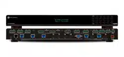
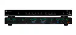
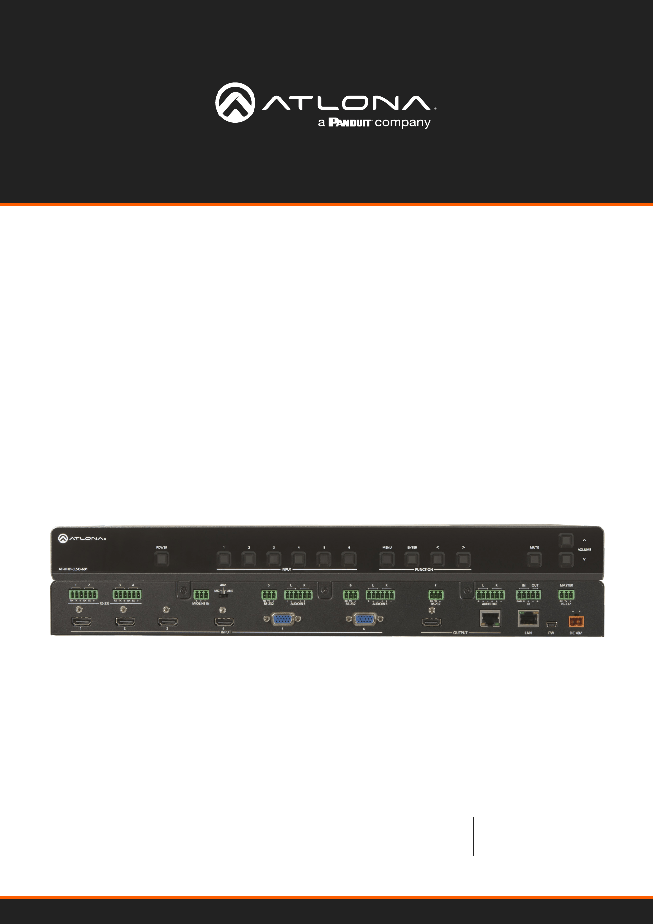
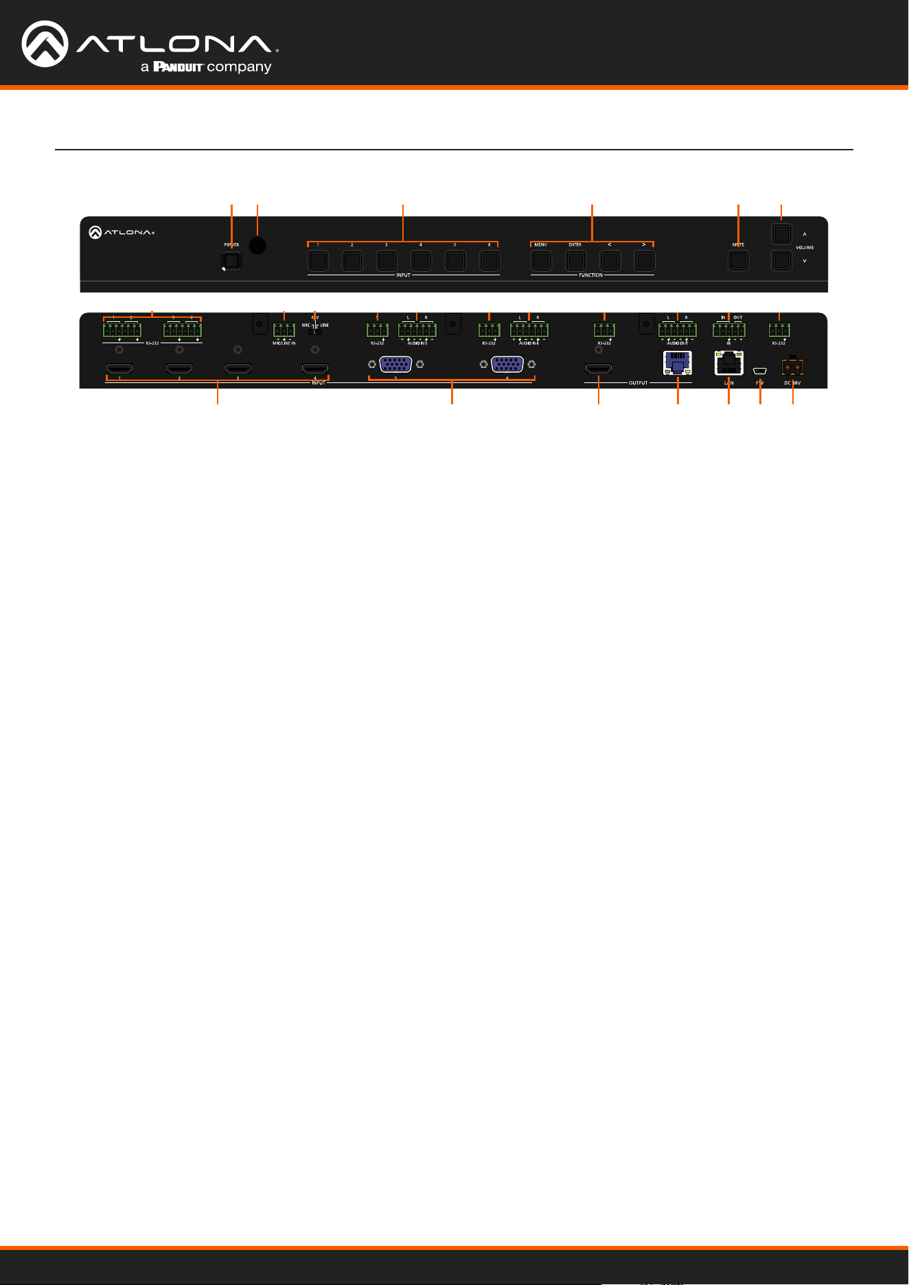
Panel Description
-
+
RX TXRX TXRX
TX
RX TX
RX
TX
RX
TX
RX TX
RXPWR IR
MASTER
TX
AT-UHD-CLSO-601
1 POWER button
Use to turn the unit on or place into standby. LED will
illuminate blue for on and red for standby.
2 INPUT buttons
Select the button that corresponds with the inputs.
The currently selected input will illuminate blue.
3 INPUT buttons
Select the button that corresponds with the inputs.
The currently selected input will illuminate blue.
4 FUNCTION buttons
Use these buttons to open, navigate, and select
items within the on screen display menu.
5 MUTE Button
Use to mute and unmute the output audio.
6 Volume Buttons
Increase and decrease the output volume.
7 RS-232
Use for device control.
8 MIC/LINE IN
Connect microphone or line input to this port.
9 MIC/LINE Dip Switch
Use to switch between MIC, 48V, and line level input.
10 AUDIO IN
Connect 2CH audio sources to these ports.
11 AUDIO OUT
Connect to an audio DSP, amplier, or other audio
distribution devices.
12 IR IN/OUT
Connect an a control system or IR receiver to the IR
IN port. Connect an IR blaster/emitter to the IR OUT
port for local device control.
13 MASTER RS-232
Connect a control system to this port for control of
the switcher.
14 HDMI IN
Connect HDMI sources here (DVI or DisplayPort
compatible with adapters).
15 VGA IN
Connect analog video sources here. Compatible with
component, composite, and S-Video signals.
16 HDMI OUT
Connect to a local display.
17 HDBaseT OUT
Connect a CAT5e/6/6a/7 cable from this port to a
compatible HDBaseT receiver or HDBaseT display.
(e.g. AT-UHD-EX-100CE-RX).
18 LAN
Connect an Ethernet cable from this port to a Local
Area Network (LAN).
19 FW
Connect a mini USB cable from this port to a PC to
rmware update the unit.
20 DC 48V
Connect the included DC 48V power supply to this
port.
14
16
15 2017 18 19
1 2 3 4 5
7 7 10 10 11 12 13 7 78 9
6
AT-UHD-CLSO-601
8
Installation
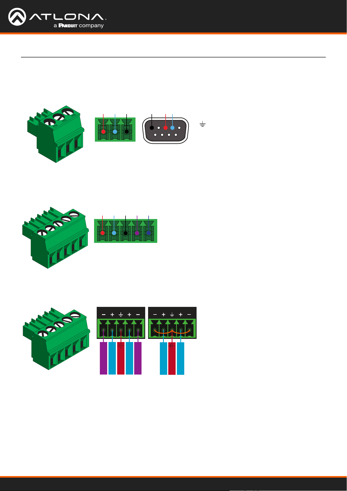
Captive Screw Connections
Audio
Connect the input to any audio device and the output to an audio DSP, amplier, or other audio distribution devices.
RS-232
IR
A 3-pin captive screw connector has been included for RS-232.
Pin out will be determined by the RS-232 cable
and connect as RX (receive), TX (transmit) and
(Ground). Ground will be shared between port
1 and port 2.
GND RX
TX
GNDRX TX
Use a jumper between the negative and ground pins
when using an unbalanced connection.
Balanced
Unbalanced
ANALOG IN
L R
Negative
-
Negative
-
+
Positive
+
Positive
Ground
ANALOG IN
L R
+
Positive
+
Positive
Ground
A 5-pin captive screw connector has been included for IR control of the unit and local devices. Connect a control
system or IR receiver to the IR IN port and a IR emitter to the IR OUT port.
IR IN is connected by a power, ground, and signal wire. Use
a 12V IR receiver with this port or connect a compatible
control system. (e.g. AT-IR-CS-RX purchasable through atlona.com)
IR OUT is connected by a ground and signal wire. Use the
included IR emitter with this port.
IR IN
IR OUT
GND
-+
S
P
AT-UHD-CLSO-601
9
-
+
RX TXRX TXRX
TXRX TX RX
TX
RX
TX
RX TX
RXPWR IR
MASTER
TX
AT-UHD-CLSO-601
-
+
RX TXRX TXRX
TXRX TX RX
TX
RX
TX
RX TX
RXPWR IR
MASTER
TX
AT-UHD-CLSO-601
-
+
RX TXRX TXRX
TXRX TX RX
TX
RX
TX
RX TX
RXPWR IR
MASTER
TX
AT-UHD-CLSO-601
-
+
RX TXRX TXRX
TXRX TX RX
TX
RX
TX
RX TX
RXPWR IR
MASTER
TX
AT-UHD-CLSO-601
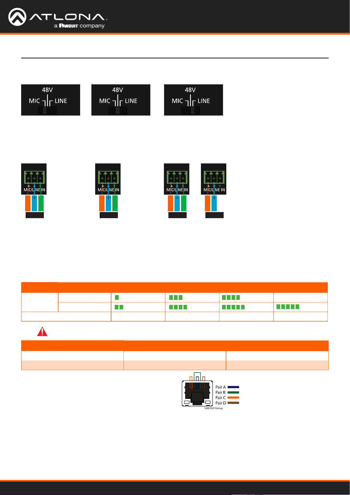
MIC / LINE
Connect dynamic
or self-powered
microphones in this
mode.
Use this setting for
phantom powered
microphones. Supplies 48
volts.
Connect wireless microphone
receivers (or other sources) with line
level outputs using this setting. Either
balanced, unbalanced, mono, or two
channel connections may be used.
Negative
-
Negative
-
Negative
-
+
Positive
+
Positive
+
Positive
+
Positive
Ground
Ground
Ground
Ground
MIC MIC LINE LINE
Balanced Balanced Balanced Unbalanced
Refer to the tables below for recommended cabling when using Altona products with HDBaseT. The green bars
indicate the signal quality when using each type of cable. Higher-quality signals are represented by more bars.
Core Shielding CAT5e CAT6 CAT6a CAT7
Solid UTP (unshielded) N/A
STP (shielded)
Performance Rating (MHz) 350 500 600 800
Use of a TIA/EIA 568B
termination is recommended
for optimal performance.
Cable Max. Distance @ 4K Max. Distance @ 1080p
CAT5e 295 feet (90 meters) 330 feet (100 meters)
CAT6 / CAT6a / CAT7 330 feet (100 meters) 330 feet (100 meters)
IMPORTANT: Stranded or patch cables are not recommended due to performance issues.
Cable Recommendation Guidelines
-
+
RX TXRX TXRX
TXRX TX RX
TX
RX
TX
RX TX
RXPWR IR
MASTER
TX
AT-UHD-CLSO-601
-
+
RX TXRX TXRX
TXRX TX RX
TX
RX
TX
RX TX
RXPWR IR
MASTER
TX
AT-UHD-CLSO-601
-
+
RX TXRX TXRX
TXRX TX RX
TX
RX
TX
RX TX
RXPWR IR
MASTER
TX
AT-UHD-CLSO-601
Installation
AT-UHD-CLSO-601
10
Installation
Mounting Instructions
AT-HDR-H2H-44M
1 2 3
4
RS-232 IR IN
HDMI IN LAN FW DC 24V
SRX TX
OUTPUT 1
OUTPUT 2
OUTPUT 3
OUTPUT 4
1 2
AT-UHD-CLSO-601
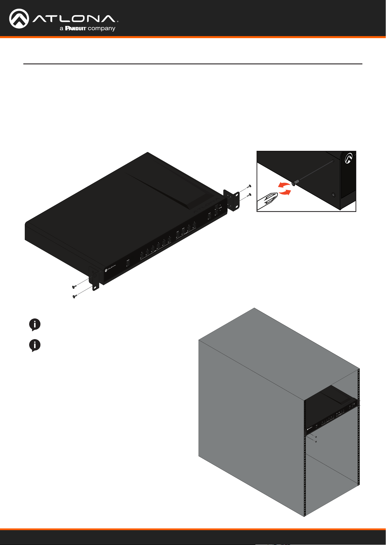
The AT-UHD-CLSO-601 can be mounted in a standard 19-inch rack or placed freestanding on top of a desk or table.
1. Remove the front two case screws from the sides of the case.
2. Attach the included rack ears to each side of the AT-UHD-CLSO-601 using the case screws.
AT-UHD
AT-HDR-H2H-44M
1 2 3
4
RS-232 IR IN
HDMI IN LAN FW DC 24V
SRXTX
OUTPUT 1
OUTPUT 2
OUTPUT 3
OUTPUT 4
AT-UHD-CLSO-601
EDID INFO
NOTE: Increase the air ow as needed to maintain
the recommended temperature inside the rack.
NOTE: Do not exceed the maximum weight loads
for the rack. Install heaver equipment in the lower
part of the rack for stability.
3. Install the AT-UHD-CLSO-601 into a rack, using four rack screws.
Rack Installation

AT-UHD-CLSO-601
11
Installation
The CLSO-601 multi-function analog inputs (Input 5 and 6) can be used with most analog video signal formats
including VGA (with DDC), RGBHV (without DDC), component (YUV), S-Video, or composite video. Balanced analog
audio can be input and embedded using the provided captive screw connectors.
Each format can be directly accessed from RS-232, IR, or IP control. Front panel buttons sequentially progress
through each input format. The last format used is the rst source selected when returning to these inputs. Unused
formats can be removed from the sequence using WebGUI, RS-232, or IP.
VGA (m) to BNC, VGA (m) to RCA, and S-Video to 2 BNC adaptors can be used to connect sources to these inputs.
VGA
Use a VGA to VGA cable to ensure that the Preferred Resolution DDC is communicated to your source.
RGBHV
Use a HD-15 (VGA) to 5 BNC breakout cable for this format. An existing RGBHV analog matrix switch can be
connected here to maintain full function of the analog matrix.
Component
YUV (YPbPr) signal from DVD (or other sources) can be input to the CLSO-601 using the green (Y), blue (Pb), and
red (Pr) connections on a HD-15 (VGA) to 5 BNC breakout cable or with a common VGA (m)-Component (3 RCA m)
adaptor.
S-Video
YC signal from a VCR or teleconference system can be input to the CLSO-601 using the blue (Y), and green (C)
connections on a HD-15 (VGA) to 5 BNC (m) breakout cable and a common S-Video (m) to 2 BNC (f) adaptor
Composite
NTSC, PAL, or Secam video signals can be input to the CLSO-601 using the blue connection on a HD-15 (VGA) to 5
BNC (m) breakout cable.
A common application for this type of input would be to connect a RGBHV matrix switcher to the CLSO-601. Then
each input to the matrix could be connected to a dierent format analog signal. A 3rd party control system could
ensure the correct format is selected to match the input to the switcher.
Analog Multi-Function Inputs

AT-UHD-CLSO-601
12
Control
CEC
RS-232
TCP/IP
WebGUI
CEC is available for trigger through RS-232, TCP/IP, and WebGUI. The trigger commands for RS-232 and TCP/IP can
be found within the API at https://atlona.com/pdf/AT-UHD-CLSO-601_API.pdf.
RS-232 control for connected devices and the unit are available through the RS-232 captive screw connection. The
commands can be found within the API at https://atlona.com/pdf/AT-UHD-CLSO-601_API.pdf.
TCP/IP control for connected devices and the unit are available through the LAN connection. The commands can be
found within the API at https://atlona.com/pdf/AT-UHD-CLSO-601_API.pdf.
The unit has a built in web UI that will allow for unit conguration and device control. See the webGUI section for
more information.
AT-UHD-CLSO-601
13
3
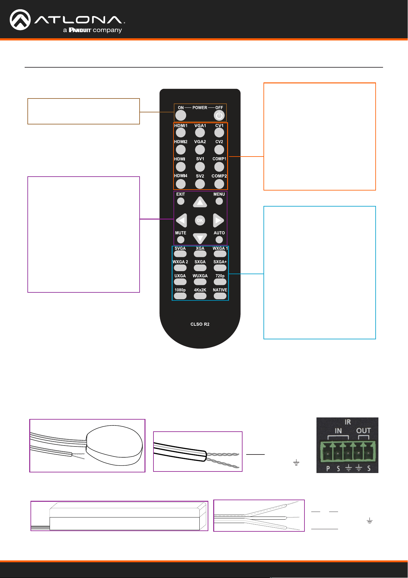
Power
On - turns CLSO-601 on
O - sets CLSO-601 into standby
Source Selection
HDMI1 - Input 1
HDMI2 - Input 2
HDMI3 - Input 3
HDMI4 - Input 4
VGA1 - Input 5
VGA2 - Input 6
SV1 - Input 5 (S-Video 1)
SV2 - Input 6 (S-Video 2)
CV1 - Input 5 (Composite 1)
CV2 - Input 5 (Composite 2)
COMP1 - Input 5 (Component 1)
COMP2 - Input 6 (Component 2)
Output Resolution Selection
SVGA - 800x600
XGA - 1024x768
WXGA1 - 1280x800
WXGA2 - 1360x768
SXGA - 1280x1024
SXGA+ - 1440x900
UXGA - 1600x1200
WUXGA - 1920x1200
720p
1080p
4Kx2K - 3840x2160
Native - Upscales/downscales
the output signal to match
the HDBaseT display’s
preferred resolution
Controls
Menu - Pulls up on screen display
menu - also serves as back
button
Exit - Closes on screen display
menu
Arrows - Use to navigate the on
screen display menu and
adjust volume
OK - Enter button, use to select
choices within the on
screen display menu
Mute - Silences all audio outputs
Auto - Auto VGA setup
System IR is typically used to connect to control system processors. This input is used to control the CLSO-
601.
Note: The IR receiver is optional for the UHD-CLSO-601. The compatible IR receiver (AT-IR-CS-RX) can be purchased
through atlona.com.
The wires of the emitter and receiver have been marked to differenciate the pin outs.
The included IR emitter has two wires: signal and ground. Signal will have a solid line and ground will be
blank. The IR emitter will plug into the IR OUT ports.
There are three wires on the IR receiver (sold separately): signal, ground, and power. Signal has a dotted line,
ground will be blank, and power will have a solid line. The IR receiver will plug into the IR IN ports.
Signal (S)
Ground ( )
Signal (S)
Ground ( )
Power (P)
IR Remote
AT-UHD-CLSO-601
14
On Screen Display
Input Input 1 HDMI 1
Input 2 HDMI 2
Input 3 HDMI 3
Input 4 HDMI 4
Input 5 VGA 1
Component 1
Composite 1
S-Video 1
Input 6 VGA 2
Component 2
Composite 2
S-Video 2
Audio Volume Master -80 to +10db
Sub HDMI 1 -80 to +10db
HDMI 2 -80 to +10db
HDMI 3 -80 to +10db
HDMI 4 -80 to +10db
Analog 1 -80 to +10db
Analog 2 -80 to +10db
Analog 3 -80 to +10db
Line In -80 to 0db
Bass -10 to 12 dB
Treble -10 to 12 dB
Video Contrast 0 to 100
Brightness 0 to 100
Sharpness 0 to 30
Color 0 to 100
Tint 0 to 100
H Position 0 to 40
Phase 0 to 63
NR BNR Disabled
Low
Medium
High
MNR Disabled
Low
Medium
High
RNR Disabled
Low
Medium
High
Scale Full
Overscan
Underscan
Letterbox
Panscan
Follow Input
On-Screen Display (OSD)
AT-UHD-CLSO-601
15
On Screen Display (OSD)
On Screen Display
Setup Language English
Spanish
French
German
OSD Settings Transparency
Position Horizontal
Vertical
Menu Timer 10 sec
30 sec
60 sec
Info Banner On
O
Output Format HD Pass Through
480i@60 (NTSC)
480p@60
720p@60
1080i@60
1080p@60
576i@50 (PAL)
576p@50
720p@50
1080i@50
1080p@50
1080p@24
Native
UHD 3840x2160p@24
3840x2160p@25
3840x2160p@30
4096x2160p@24
4096x2160p@30
PC-1 640x480@60
640x480@72
640x480@75
800x600@60
800x600@72
800x600@75
1024x768@60
1024x768@72
1024x768@75
PC-2 1280x768@60
1280x800@60
1280x960@60
1280x1024@60
1360x768@60
1366x768@60
1400x1050@60
1440x900@60
1600x900@60
1600x1200@60
1920x1200@60
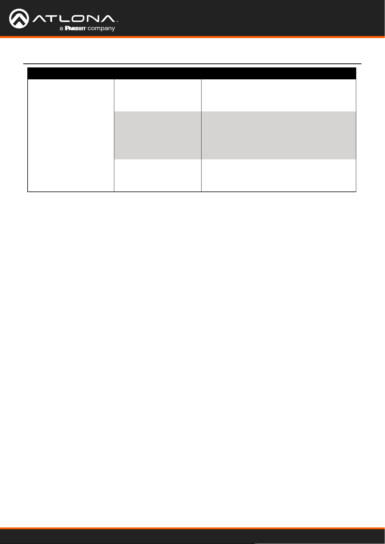
Network Network Status MAC Address
xx-xx-xx-xx-xx-xx
IP Address
xxx.xxx.x.xxx
Subnet
xxx.xxx.xxx.x
Gateway
xxx.xxx.x.x
DHCP ON
OFF
Note: After selecting a new language, close the menu and reopen it for the change to take eect.
AT-UHD-CLSO-601
16
On Screen Display
Status System Info Software Revision
OSD Revision
FPGA Revision
On-Time (h-m)
x.x.xx (e.g. 1.0.01)
x.x.x (e.g. 1.0.0)
x.x.x (e.g. 1.0.0)
x:xx (e.g. 1:15)
Video Info Input
Signal Type
Video Format
Aspect
Color Space
Color Depth
xxxx (e.g. HDMI 1)
xxxx (e.g. HDMI)
xxxx (e.g. 1080i@60)
xxxx (e.g. 16x9)
xxxx (e.g. YUV)
xxxx (e.g. 24)
Audio Info Input
Audio Format
Sampling Rate
Channels
xxxx (e.g. HDMI 1)
xxxx (e.g. PCM)
xxxx (e.g. 48 KHz)
xxxx (e.g. 2-Ch)
On Screen Display (OSD)
AT-UHD-CLSO-601
17
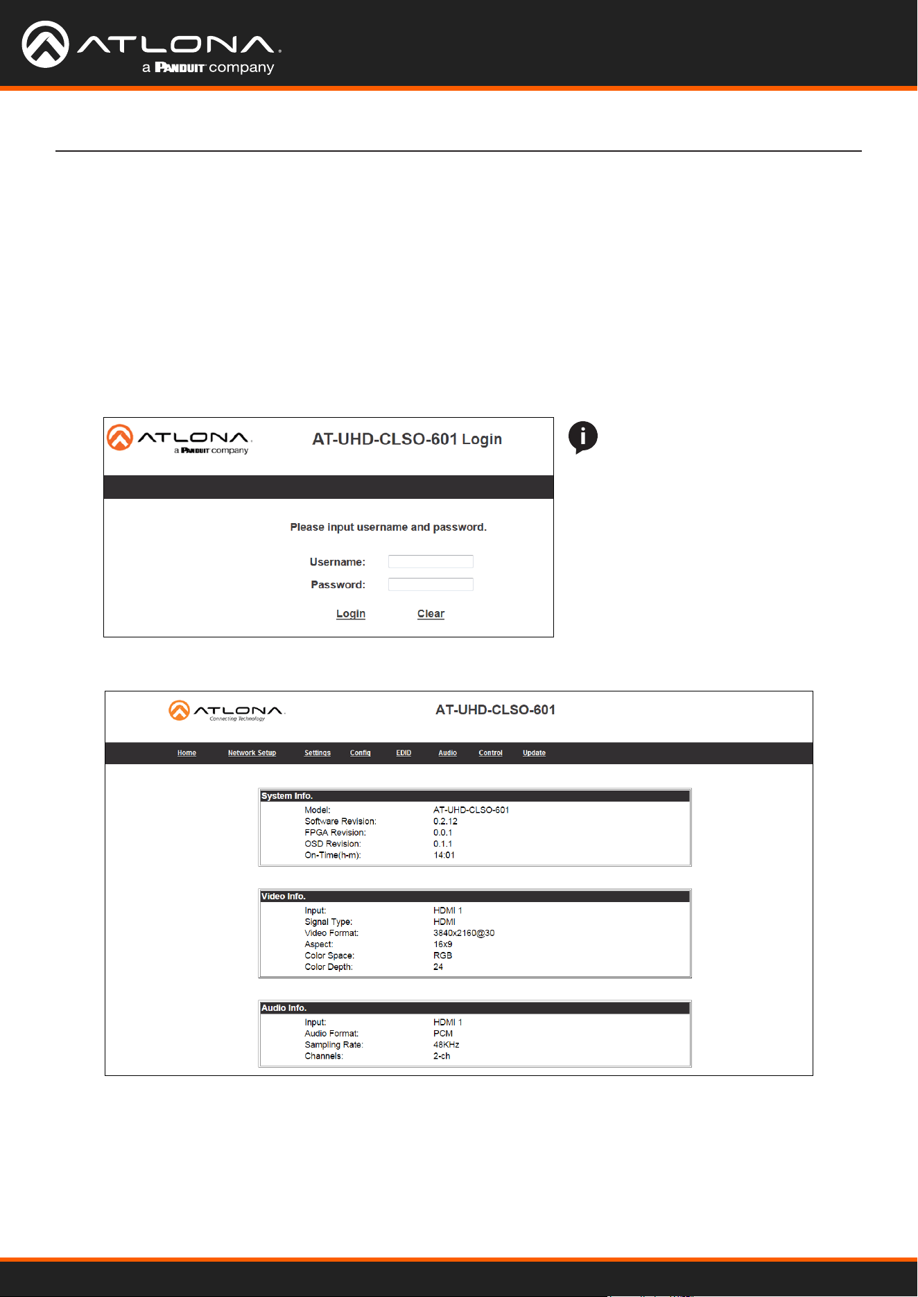
WebGUI
The AT-UHD-CLSO-601 includes a built-in webGUI, which allows easy remote management and control of all
features. Follow the instructions below to access the webGUI.
1. Make sure that an Ethernet cable is connected between the LAN port on the AT-UHD-CLSO-601 and the
network.
2. Use an IP scanner to determine the IP address of the unit.
3. Launch a web browser and enter the IP address in the address bar.
4. The AT-OME-PS62 Login page will be displayed.
5. Enter the following information on the Login page.
Login: root
Password: Atlona
NOTE: If the login and password
are entered wrong six times, the
unit will lock the login screen for
two minutes.
6. Click the Login button. The info page will display, giving all the general information of the AT-UHD-CLSO-601.
AT-UHD-CLSO-601
18
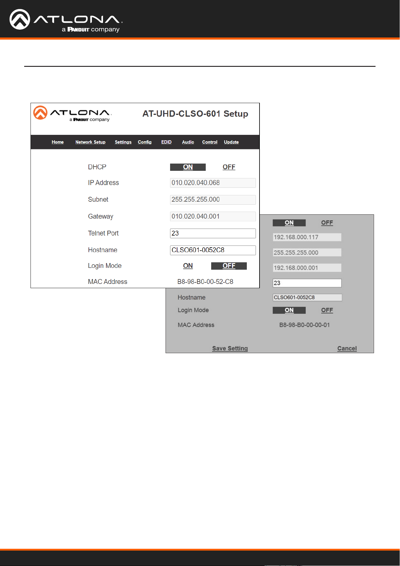
Select Network Setup from the top navigation to adjust IP information.
Network Setup
Network
DHCP - Switch between static (OFF) and DHCP (ON) IP modes.
IP, Netmask, Gateway - This will display the unit’s current DHCP IP settings. When set to static, ll in the IP
address, netmask, and gateway.
Telnet Port - Set the telnet port if needed for control. Default port is 23.
Hostname - Set the name for the matrix, this will show up in network discovery.
Login Mode - Toggle telnet login mode on and o. If on, a username and password will be required to control
the unit via telnet.
MAC Address - Displays the MAC address of the unit.
WebGUI
AT-UHD-CLSO-601
19
WebGUI
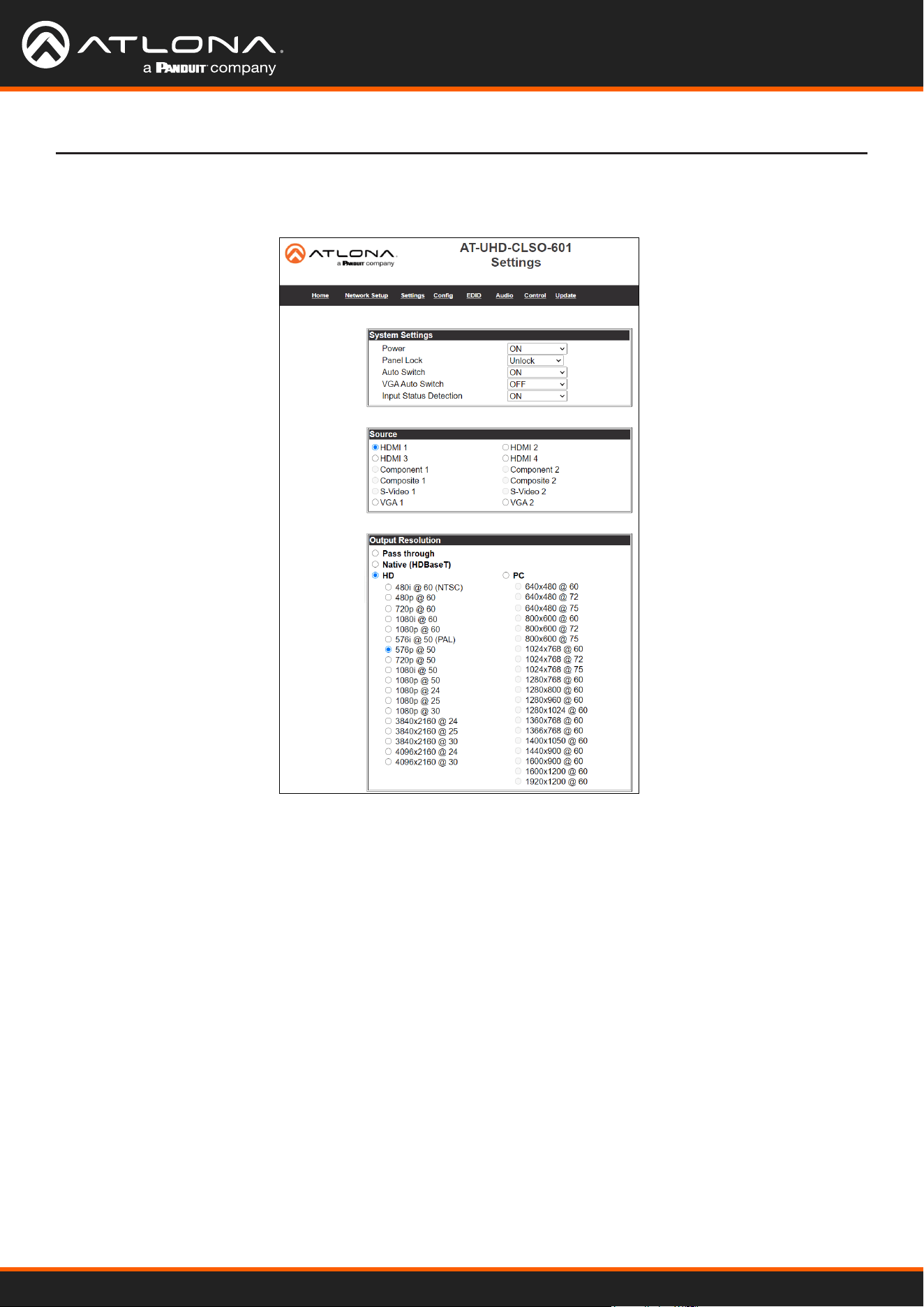
Select Settings from the top navigation to adjust routing and video settings.
Settings
Output Resolution
Switch between multiple video output resolutions:
Pass through - Input video will pass to the display without being scaled
Native - Upscales/downscales the output signal to match the HDBaseT display’s preferred resolution
HD - Will upscale/downscale the output signal to match the selected HD resolution
PC - Will upscale/downscale the output signal to match the selected PC resolution
Note: When the output is set to UHD resolutions, UHD sources are passed through without scaling. Frame rates
are not changed. (e.g. if 3840x2160@30Hz input is received, output will remain 30Hz even if output is set to 24Hz)
System Settings
Power - Turn the switcher on and o
Panel Lock - Locks/unlocks the front panel buttons, or just the menu when Lock Menu is selected
Auto Switch - Turns auto switching between HDMI inputs on/o
VGA auto switch - Turns VGA auto switching on/o
Note: VGA auto switching is only available on VGA and will not work with component, composite, and S-Video
*Component, composite, and S-Video poll settings will grey out when VGA auto switching is on*
Input Status Detection - When enabled (ON), the poll settings will display the type of input signal being received on
the VGA port.
Source
Select the input to be routed to the output.
AT-UHD-CLSO-601
20
WebGUI
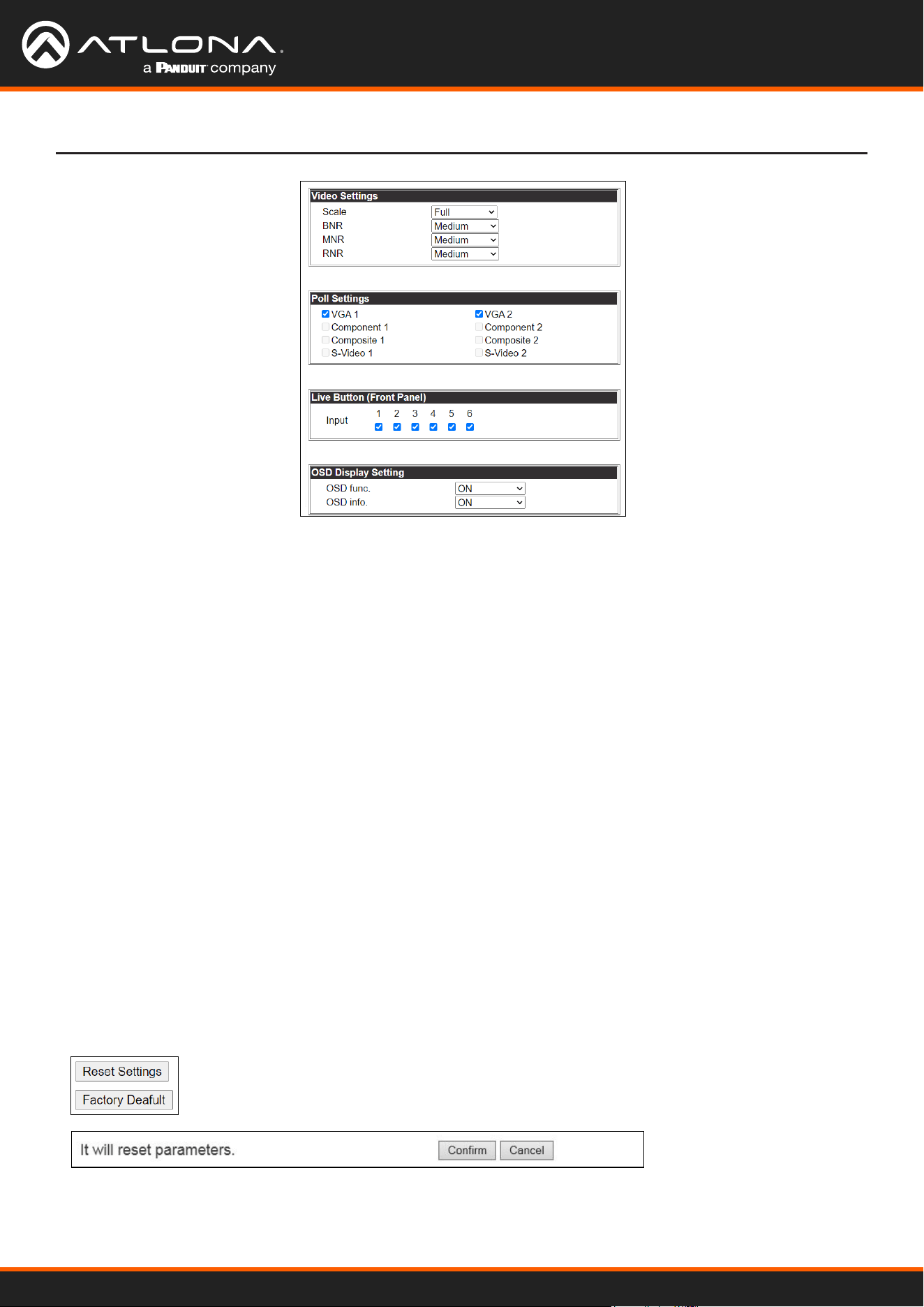
Video Settings
Set the output video settings:
Scale - Sets video output aspect ratio - Full, overscan, letter box, pan and scan, or follow input
Full - Sources always ll the screen, regardless of source aspect ratio
Overscan - Image is slightly zoomed in so that broadcast data at edges is masked
LetterBox - Used to create 16:9 aspect ratio on 4:3 aspect ratio TVs
Pan and Scan - Used to create 4:3 aspect ratio on 16:9 aspect ratio TVs
Follow Input - Aspect ratio on TV matches source aspect ratio
BNR - Block noise reduction - Disabled, low, medium, or high
MNR - Mosquoto noise reduction - Disabled, low, medium, or high
RNR - Random noise reduction - Disabled, low, medium, or high
Contrast* - Sets output white levels - 0 up to 100
Brightness* - Sets output black levels - 0 up to 100
Sharpness* - Sets output sharpness - 0 up to 30
Color* - Sets output color saturation - 0 up to 100
Tint* - Sets output hues - 0 up to 100
*Only available when outputs 5 and 6 (VGA 1 & VGA 2) are selected
Poll Settings
A check mark will appear in the box next to the signal type that is being received on the VGA port.
Note: This will only display signal type when Input Status Detection is set to ON. If set to OFF, all the signal types
will be checked.
OSD Display Settings
OSD func - Turns the CLSO’s display OSD menu on/o
OSD info - Turns the source information on the display on/o when switching
Reset Settings - Will reset the parameters to default settings on the current page only.
Factory Default - Select to reset CLSO back to factory settings.
Note: This will reset the switcher to factory default, including: resolutions, audio settings, HDCP settings, etc.
AT-UHD-CLSO-601
21
WebGUI
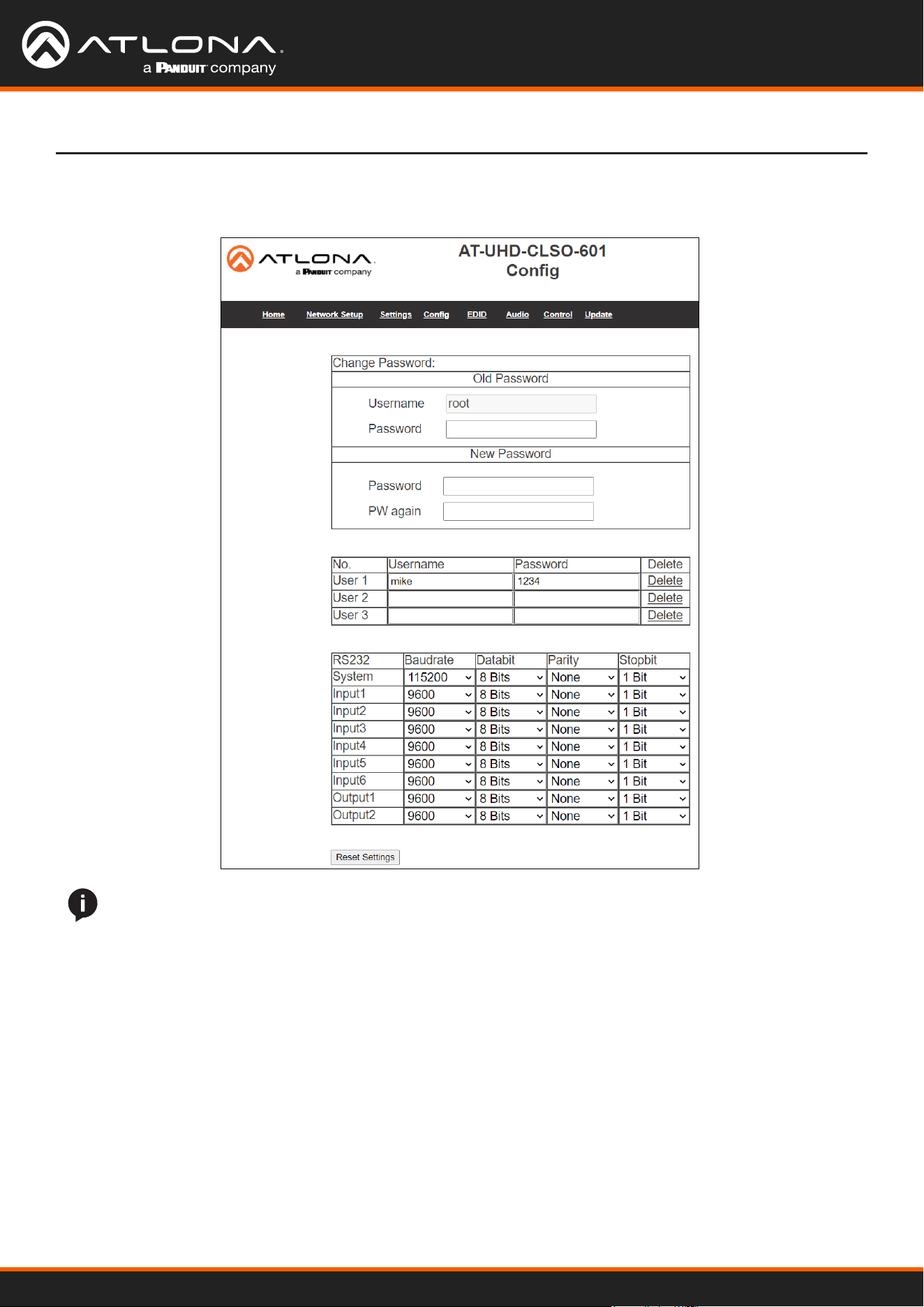
Select Cong from the top navigation to adjust passwords, add new users, and adjust RS-232 settings.
Change user name and password
Update the admin password for the switcher. Only the admin password may be changed, the username will
remain root.
User and password
Add new users and passwords here. These users will not have admin priveleges and will not be able to add or
change current users.
RS-232
System - This will change the settings of the Master RS-232 ports
Inputs - These will change the settings of RS-232 ports 1 through 6
Output 1 - This corresponds with the RS-232 port 7
Output 2 - This will adjust the RS-232 settings of the HDBaseT receiver.
Cong
NOTE: User information and updating can only be seen using the admin log in.
AT-UHD-CLSO-601
22
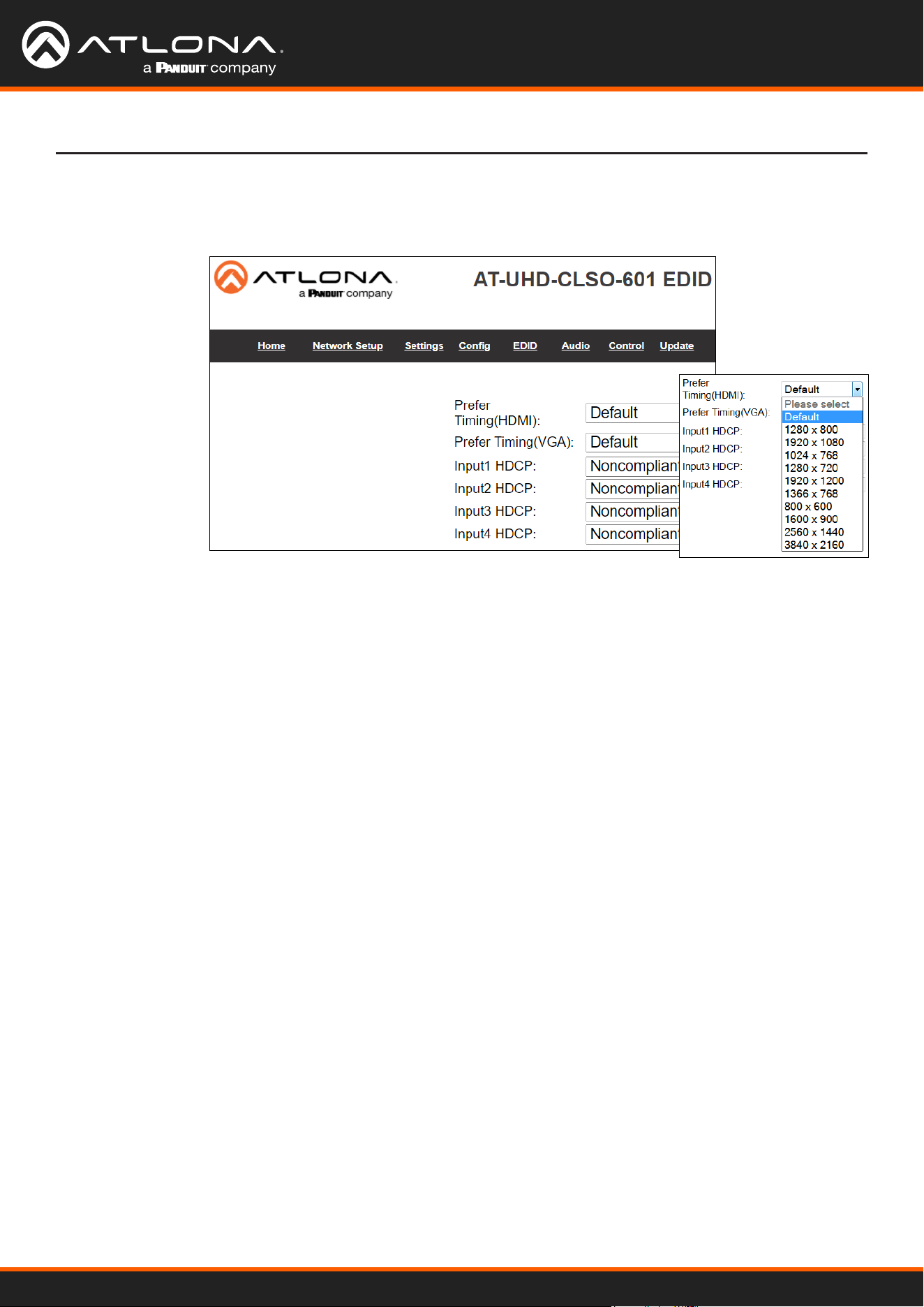
WebGUI
Select EDID from the top navigation to set the preferred timings of the input ports and to adjust HDCP compliance
reporting.
EDID
Note: CLSO-601 protects HDCP encoded content and will not pass HDCP content to a non-HDCP compliant
device.
Note: Some devices ag all content as protected when connected to an HDCP compliant display. This prevents
what should be non-protected content from reaching devices (i.e. teleconference system) through the CLSO-601.
Note: When HDCP reporting is non-compliant, only user created content is transmitted. Protected content from all
sources (e.g. BluRay, AppleTV, etc) is blocked.
Prefer Timing (HDMI)
Set the resolution of the HDMI ports.
Prefer Timing (VGA)
Set the resolution of the VGA ports..
RS-232
System - This will change the settings of the Master RS-232 ports
Inputs - These will change the settings of RS-232 ports 1 through 6
Output 1 - This corresponds with the RS-232 port 7
Output 2 - This will adjust the RS-232 settings of the HDBaseT receiver.
AT-UHD-CLSO-601
23
WebGUI
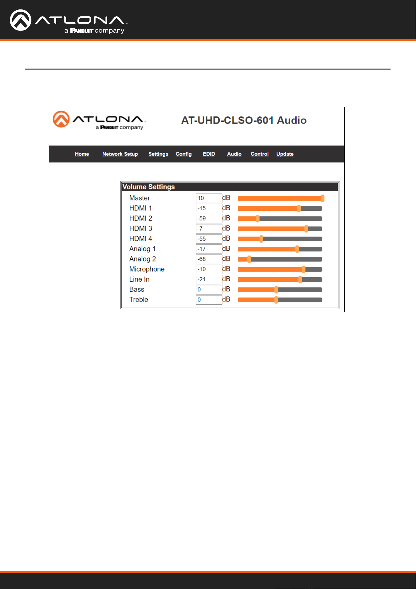
Audio settings adjust output volume for all sources including the microphone.
Master - Aects all sources at the same time
Inputs - Used to balance levels from each source.
Note: For best results, gains should be balanced between master and source levels.
Select Audio from the top navigation to set it.
Audio
AT-UHD-CLSO-601
24
WebGUI
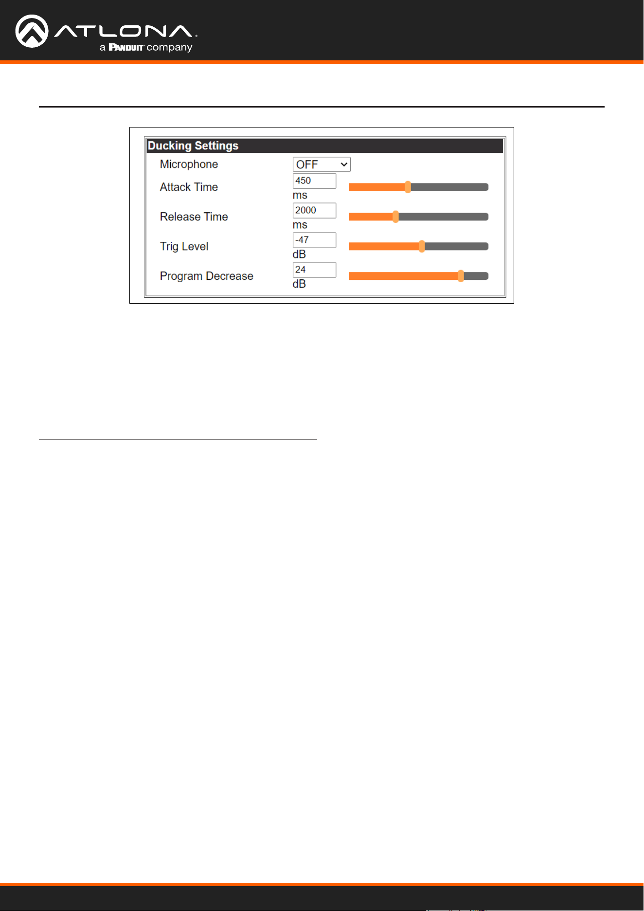
Microphone ducking uses the audio level from the microphone to decrease the program level so the speaker may be
heard.
Note: Proper set up is critical for satisfactory operation. If program levels are too high they can trigger the ducking
process.
Note: Setting the microphone volume too high may result in feedback.
It is recommended that a handheld or headset microphone be used with ducking to reduce feedback and maximize
the dierence between voice and program levels.
Best results are received with the following sequence:
1. Set master volume to 0. (This is 10 db below maximum)
2. Raise appropriate microphone (or line in) volume until just below feedback or adequate volume is reached
(whichever setting is lower). - Master level and amplier gains may be increased to get appropriate levels
Note: If feedback occurs and volume is not adequate, move the speakers and/or microphone to eliminate feedback.
3. Raise source “sub” volumes to appropiate levels without talking
4. Set attack time to minimize popping, but still fast enough that initial talking sounds are heard.
5. Set release time so that program levels do not increase between sentences.
Note: Shorten time so that the microphone doesn’t interfere with the program.
6. Set the trigger level so that words spoken at a normal level trigger the ducking process
Note: Set the trigger level too sensitive and the program will trigger the ducking. Set too low and the speaker will
have to talk very loudly to trigger ducking. The further right the slider is, the more sensitive the setting.
7. Set program decrease to ensure when ducking is triggered the program level is low enough the speaker can be
heard.
Fine tuning these settings will help achieve the best results.
AT-UHD-CLSO-601
25
WebGUI
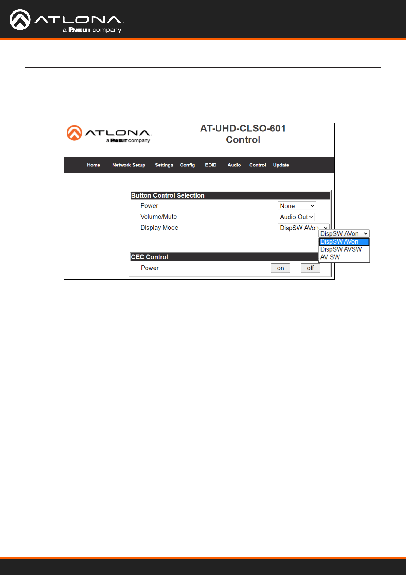
Button Control Selection
Power - Set which device the power button controls
None: Power button will turn the UHD-CLSO-601 on and o
RS-232: Power button will send power on/o command over HDBaseT using RS-232 to
compatible receivers and displays
IP: Power button will send power on/o command over Ethernet using either the LAN
connection or the HDBaseT connection
Volume/Mute
Audio Out: Volume and mute buttons will control volume output of the switcher
RS-232: Volume/Mute buttons will send the commands over HDBaseT using RS-232 to
compatible receivers and displays
IP: Volume/Mute buttons will send the commands over Ethernet using either the LAN
connection or the HDBaseT connection
Display Mode -
DispSW AVon: Display switches on/o, source audio/video signal always on
DispSW AVSW: Display switches on/o, source audio/video signal switches on/o
AV SW: Display is always on, source audio/video signal switches on/o
CEC Control
Power
On - Sends a command over HDBaseT to the HDMI output of the connected receiver to turn
the connected display on
O - Sends a command over HDBaseT to the HDMI output of the connected receiver to turn
the connected display o
Note: CEC may not work with every display type
Select Control from the top navigation to enable and congure switcher and display control. The Control page
provides a way to program button functions, turn auto switching on/o, and determine the type of control commands
(TCP/IP or RS-232) sent out.
Control
AT-UHD-CLSO-601
26
WebGUI
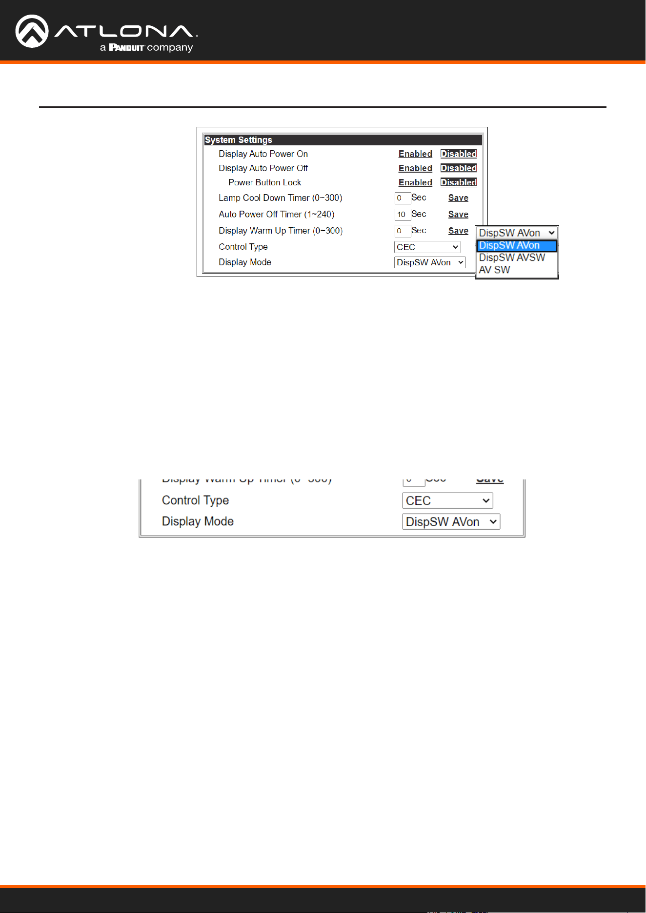
System Settings
Display Auto Power - Enable to send the programmed command to the display to turn on or o when detecting or
losing A/V signals.
Auto power o timer - Sets the period of time between the loss of A/V signal and when the display o command
is sent. Default is 15 seconds and can be adjusted from 5 seconds to 1 hour.
Lamp cool down timer (Sec.) - Sets the time between when projector lamp has been turned o to when it can
receive new commands. Default is 10 seconds and can be adjusted from 10 seconds to 300 seconds.
Display Warm-Up Timer (Sec.) - Sets the time between when the projector lamp has been turned on to when it can
receive new commands. Default is 10 seconds and can be adjusted from 10 seconds to 300 seconds.
Control Type - By default, CEC is selected for control of the display. IP and RS-232 can also be selected. When IP
or RS-232 are selected, more elds are available.
TCP/IP Settings of Controlled Device (only available when IP is selected)
IP Mode - Toggle telnet login mode between Non-Login and Login. If set to Login, a username and password
will be required to control the controlled device via TCP/IP.
IP Address - Sets to the IP of the controlled device/display.
Telnet Port - Set the telnet port of the controlled device for control. Default is 23.
Username & Password - Sets the username and password that is required when login mode is enabled.
AT-UHD-CLSO-601
27
WebGUI
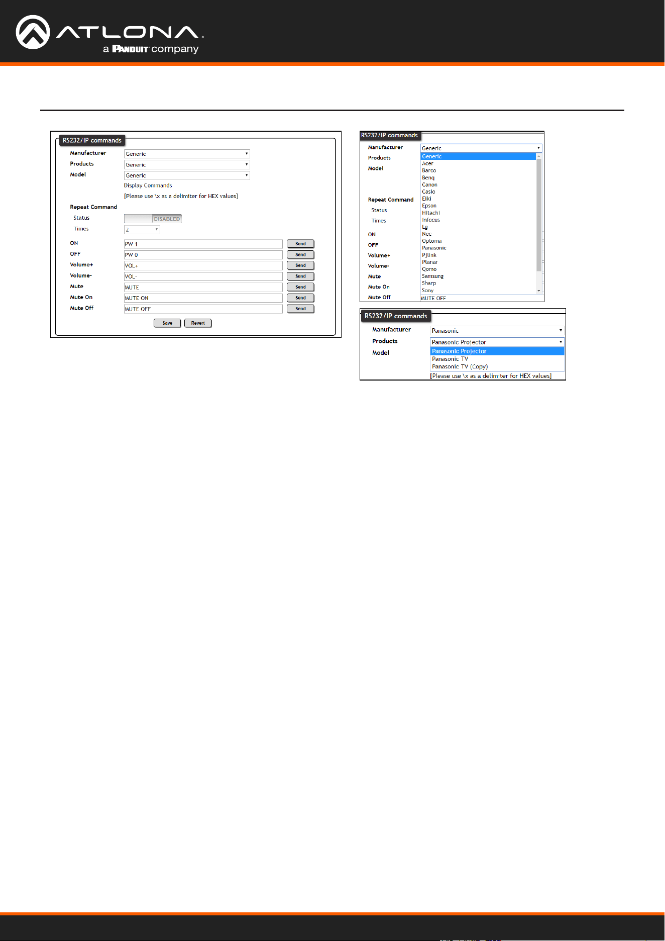
RS-232 / IP Commands
Manufacturer, Products, Models - Select the make and model of the display for control. Commands have been
programmed into the PS62 for a wide range of products. If the current display is not found within the database,
use generic and manually adjust the command elds.
Repeat Command - Enable Status to repeat the commands. Default repeat number is 2 and can be adjusted
from 2 to 4 times.
Commands: On/O/Volume/Mute - These elds will automatically be lled with the correct command when
selecting a manufacturer and product from the drop down menus. If manually entering the commands, type
them into the elds next to the command name.
Send - Use this button to send the command to the display, this can be used while manually typing the
commands to ensure the commands are correct.
Save - Save the commands to the webGUI. Manufacturer, products, and Model will revert to Generic but the
commands will be saved from the previously selected and saved Manufacturer, products, and model selection.
Revert - Sets the commands back to the previously saved settings.
AT-UHD-CLSO-601
28
WebGUI
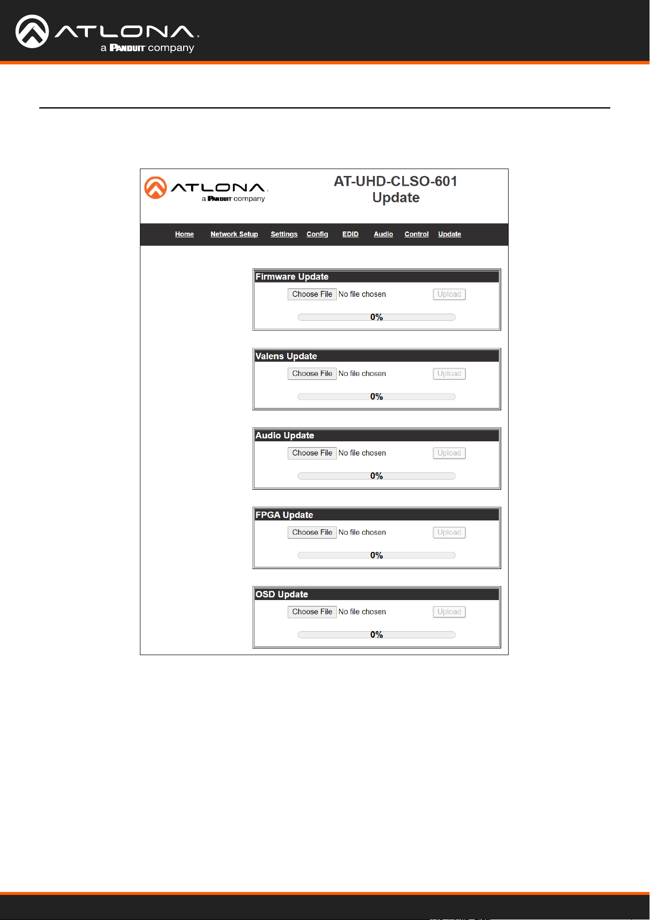
• Select the browse button for the type of rmware to be updated
- Firmware Update - MCU/Main rmware
- Valens Update - Valens rmware
- Audio Update - DSP rmware
- FPGA Update - FPGA rmware
- OSD Update - OSD rmware
• Select the new rmware le that was downloaded either from atlona.com or box.com
• Press the update button
A progress bar will display as the update is completed. After the update is complete, if a restart is required, the
webGUI will display a prompt. The rmware update is now complete and the switcher is ready to be used.
Select Update from the top navigation to update the switcher, valens, audio, FPGA, and OSD rmware.
Update
AT-UHD-CLSO-601
29
Appendix
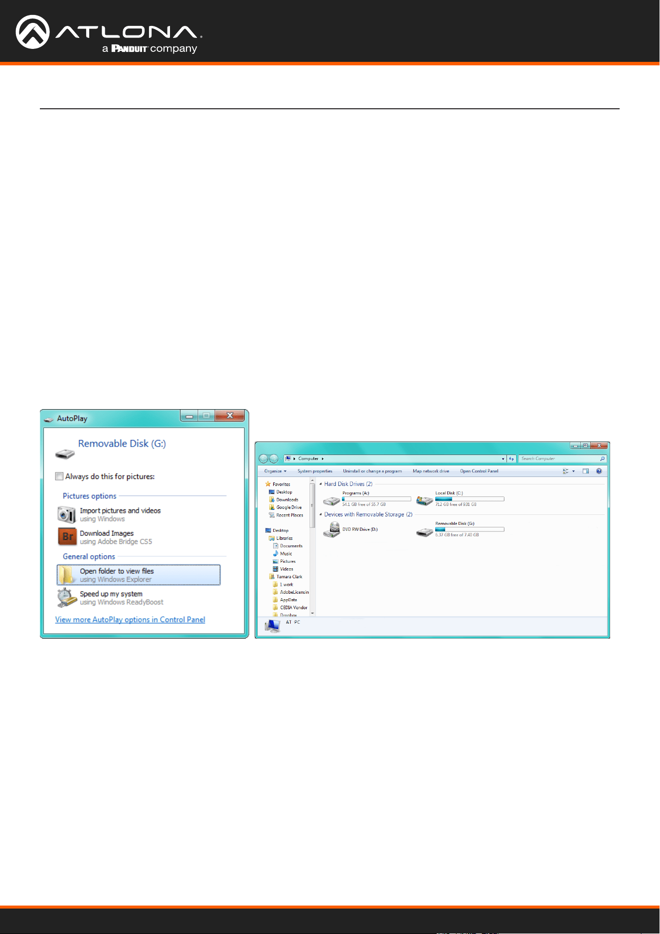
Putting the unit into update mode:
1. Unplug the power from the CLSO-601
2. Connect CLSO-601 to a computer using the mini USB to USB A cable
3. Press and hold the input key of the specic type of rmware update
Input 1 - USB/main rmware
Input 2 - OSD rmware
Input 3 - DSP/Audio rmware
Input 4 - FPGA rmware
Input 5 - Valens rmware
4. Plug the power back into the CLSO-601 (while still holding the input key)
5. Continue holding the input key for 5 seconds then release it
6. Click the option, “open folder to view les” (if AutoPlay runs)
If the computer does not auto detect the connection, open “My
Computer” and select the USB drive.
7. Place the latest rmware in the folder (if there is already a le in the folder, delete it)
8. Remove the USB cable from the CLSO-601 and computer
9. Unplug the power cable from the CLSO-601
10. Plug the power cable back in
11. Repeat the process until all rmwares are updated
The update process is complete and the switcher is ready to be used Unplug the power from the CLSO-601
Updating the Firmware
AT-UHD-CLSO-601
30
Appendix
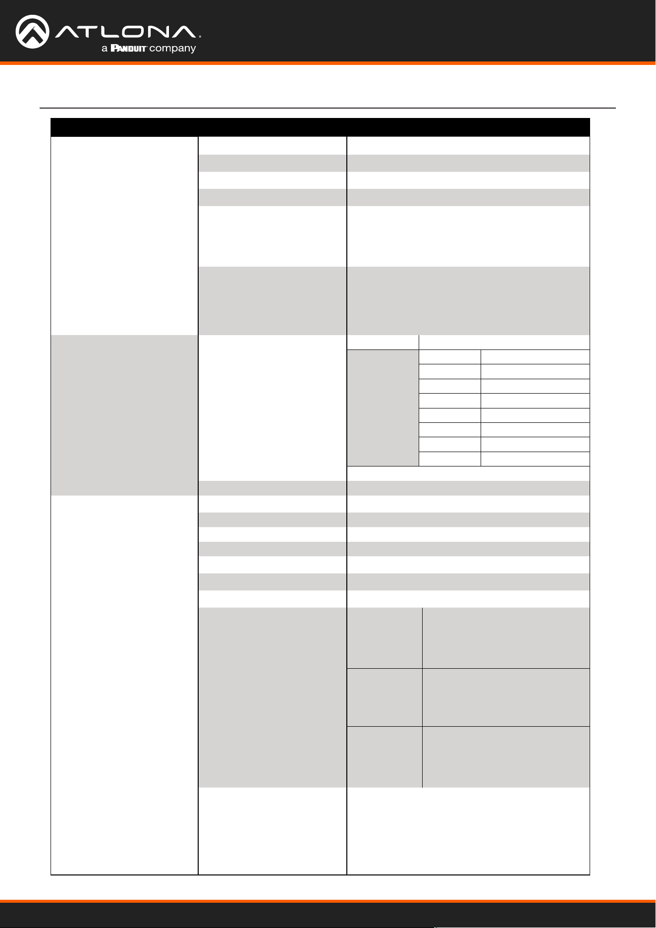
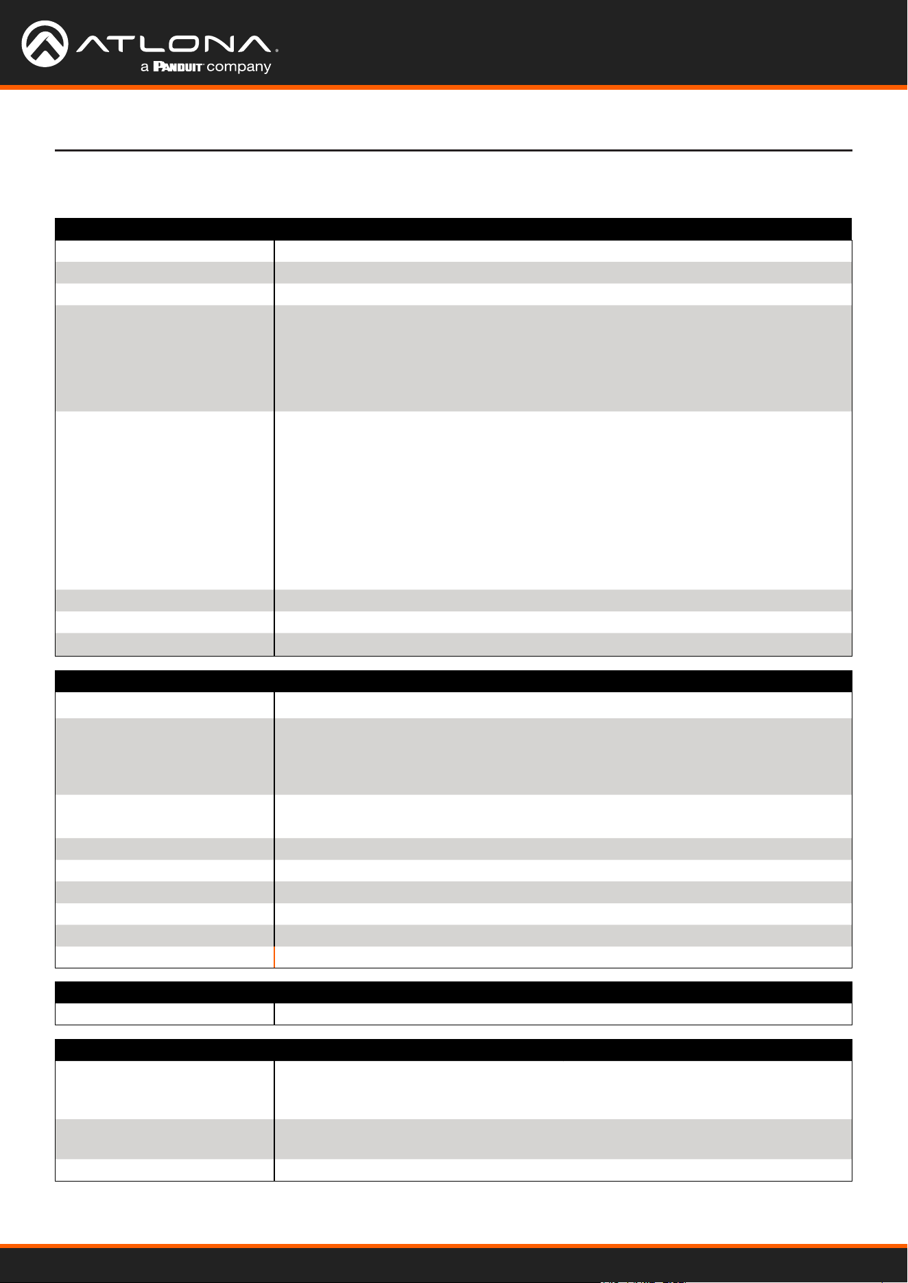
Specications
Video
HDMI 2.0
Copy Protection 1.4
Pixel Clock 300 MHz
UHD/HD
VESA
All resolutions are 60 Hz
Color Space YUV, RGB
Chroma Subsampling 4:4:4, 4:2:2, 4:2:0
Color Depth 8-bit, 10-bit, 12-bit
Audio
Analog Out LPCM 2.0
HDMI/HDBaseT Out
(pass through)
Dolby® Digital
Dolby Digital Plus™
Dolby TrueHD
Dolby Atmos®
DTS® Digital Surround™
DTS-HD Master Audio™
DTS:X®
Bit Rate 24 Mbits/s max
Analog Audio
Format 2-channel stereo
Balanced Output +4 dBu, nominal gain; +20 dBu headroom
Frequency Response 20 Hz to 20 kHz, ±0.5 dB
THD + N < 0.009% @ 20 Hz to 20 kHz
SNR > 94 dB @ 1 kHz, zero clipping @ 0 dBFS, unweighted
Sample Rate 32 kHz, 44.1 kHz, 48 kHz, 88.2 kHz, 96 kHz, 176.4 kHz, 192 kHz
4096x2160@24/30Hz
3840x2160@24/25/30Hz
[email protected]/24/25
/29.97/30/50/59.94/60
1920x1080i@50/59.94/60Hz
1280x720p@25/29.97/30/50/59.94/60Hz
720x576p
720x576i
640x480p
640x480i
2560x1440
2048x1152
2048x1080
1920x1200
1680x1050
1600x1200
1600x900
1440x1050
1440x900
1366x768
1360x768
1280x1024
1280x960
1280x800
1280x768
1024x768
800x600
640x480
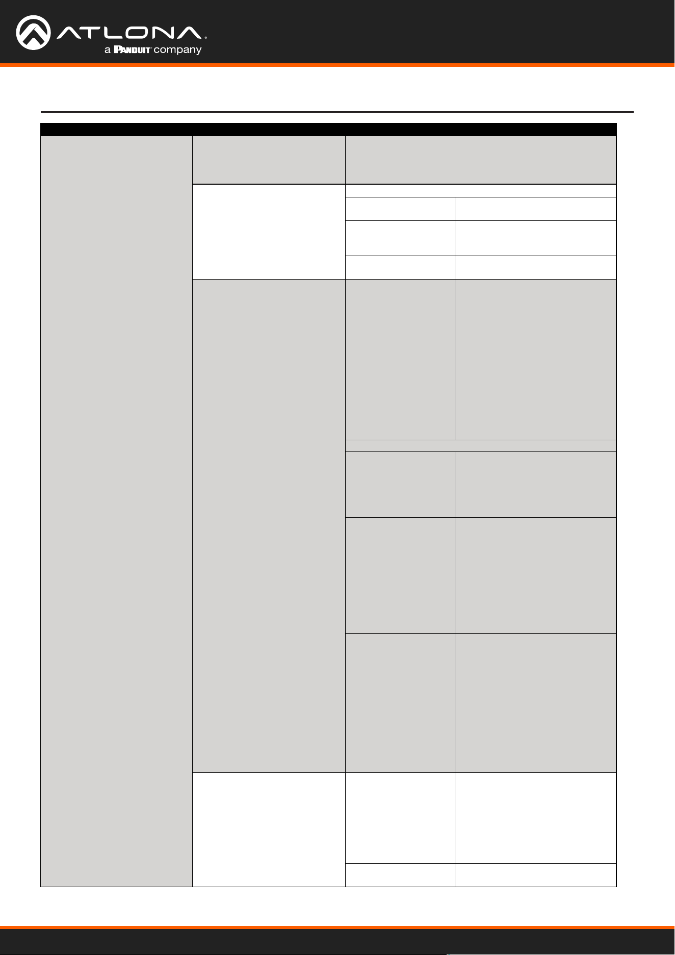
Protocols
Addressing DHCP, static
Control
RS-232 Device control and conguration
Bidirectional pass-through from control system over HDBaseT
Supported baud rates: 2400, 4800, 9600, 19200, 38400, 57600, 115200
IP Protocols: HTTPS, Telnet, mDNS
Modes: DHCP, Static – selectable through front panel and built-in web server
CEC Yes
AT-UHD-CLSO-601
31
Appendix
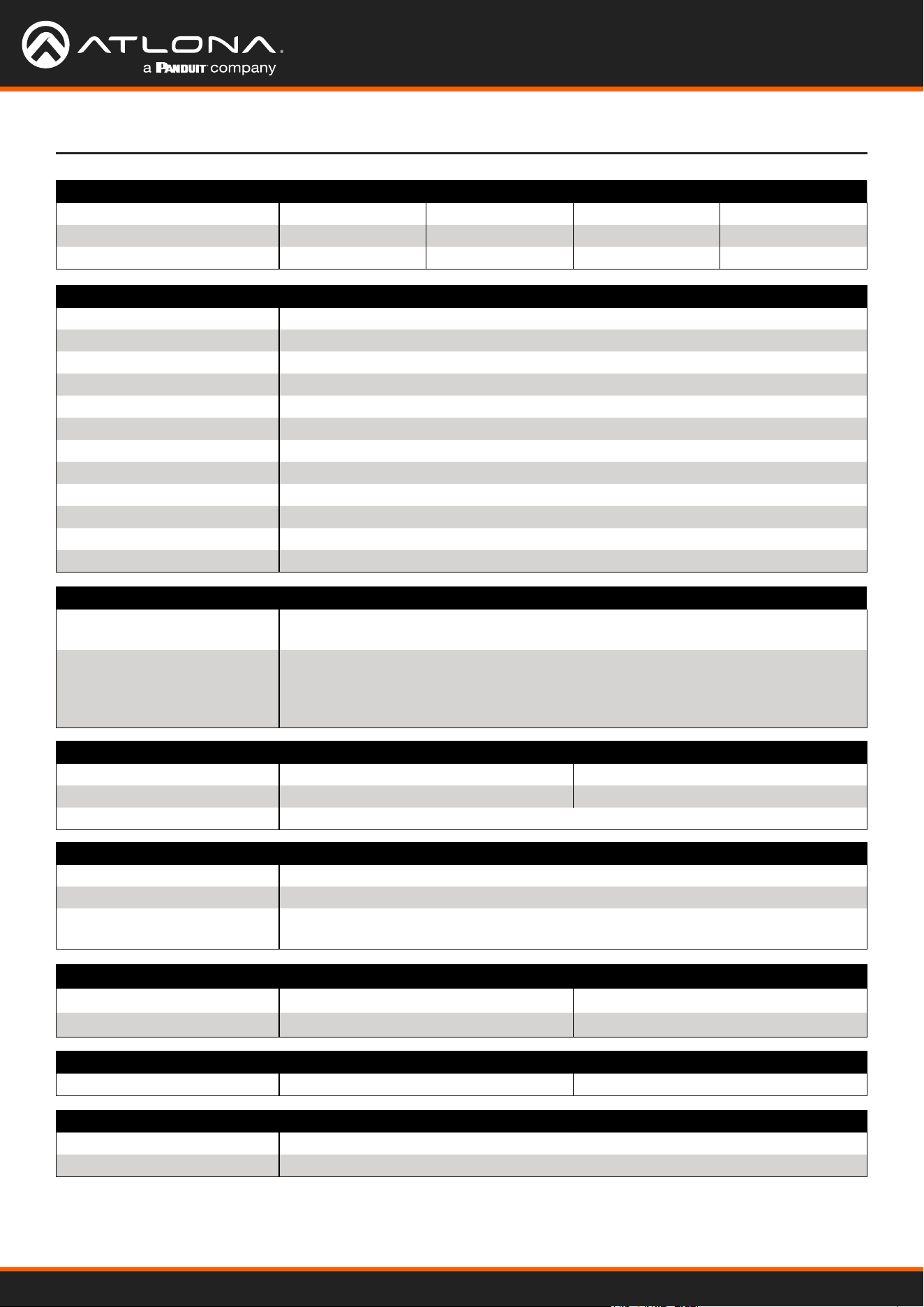
Resolution / Distance 4K/UHD - Feet / Meters 1080p - Feet / Meters
HDMI IN/OUT 15 5 30 10
CAT5e/6 230 70 330 100
CAT6a/7 330 100 330 100
Connectors
HDMI IN 4 - Type A, 19-pin female
HDMI OUT 1 - Type A, 19-pin female
VGA IN 2 - DE-15, 15-pin female
HDBaseT OUT 1 - RJ45
RS-232 2 - 6-pin captive screw, 4 - 3-pin captive screw (bidirectional)
IR 1 - 5-pin captive screw
MIC/LINE IN 1 – 3-pin captive screw
AUDIO IN 2 – 6-pin captive screw
AUDIO OUT 1 - 6-pin captive screw
LAN 1 - RJ45, 10/100/1000 Mbps
FW 1 - Micro USB
DC 48V 1 - 2-pin captive screw
Indicators and controls
INPUT 1 - INPUT 6 6 - LED, blue
POWER
INPUT 1 - INPUT 6
MENU, ENTER, >, <
MUTE, VOL UP, VOL DN
16 - momentary, tact-type
Dimensions Inches Millimeters
Device (H x W x D) 1.73 x 17.08 x 10.04 44 x 433.8 x 255
Device (w/ feet) 2.17 x 17.08 x 10.04 55.15 x 433.8 x 255
Environmental Fahrenheit Celsius
Operating Temperature +32 to +122 °F 0 to 50 °C
Storage Temperature -4 to +140 °F -20 to 60 °C
Operating Humidity (RH) 20% to 90%, non-condensing
Power
Consumption 33 W
Idle Consumption 3.1 W
External Power Supply 100 - 240 V AC, 50/60 Hz
Output: 48 V / 3.125 A DC
Weight Pounds Kilograms
Device 6.9 3.12
Certication
Device CE, FCC
Power CE, FCC, cULus, RoHS, CCC, RCM

Toll free US International
atlona.com • 877.536.3976 • 41.43.508.4321
35232-R3