
Atlona Manuals
Switchers
AT-UHD-SW-510W
Solution Setup and Conguration Guide
Five-Input Universal Matrix Switcher
with Wireless Presentation Link
4K/UHD

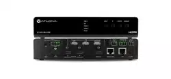
AT-UHD-SW-510W
2
Version Release Date Notes
1 Jul 2019 Initial release
Version Information

AT-UHD-SW-510W
3
Introduction 4
Solution Setup and Conguration Guide 5
Input Auto Switching 5
Display Control 7
CEC Control 7
RS-232 Control 11
Conguring IP Control 17
Scheduling Display Operation Times 19
Trigger Port 20
Wiring 20
Conguration using the Web GUI 20
Relay Port 22
Wiring 22
Operation 22
Conguration using the Web GUI 23
Table of Contents

AT-UHD-SW-510W
4
Welcome to the AT-UHD-SW-510W Solution Setup and Conguration Guide. This document covers the following
topics:
• Input Auto Switching
This section explains how to congure the AT-UHD-SW-510W to automatically switch inputs, when sources are
connected or disconnected.
• Display Control
The AT-UHD-SW-510W provides control of display (sink) devices through CEC, RS-232, or IP protocols.
Step-by-step instructions are provided on how to setup each protocol and how to enter commands.
In addition, the display can be automatically powered-on or powered-o based on the current time and date.
The “Scheduling Display Times” section will cover this procedure.
• Trigger Port and Relay Port
Each of these sections explain how to connect devices such as occupancy sensors, screens, curtains, and how
to congure the AT-UHD-SW-510W to work with these devices.
Introduction
AT-UHD-SW-510W
5
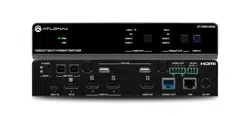
The AT-UHD-SW-510W provides auto-switching capability, which will automatically switch the input to the most
recently-connected or powered source, if a so another source is powered-down or disconnected. For example, if the
connection sequence for three separate sources is: DP IN 2 > HDMI IN 4 > HDMI IN 3, and the source connected to
HDMI IN 4 is disconnected (or powered-down), then the AT-UHD-SW-510W will automatically switch to HDMI IN 3,
since this was the last source to be connected.
Auto-switching is enabled (On), by default, and can be enabled or disabled through the web GUI.
Input Auto Switching
USB-C
DP
HDMI 3
HDMI 4
BYOD
DISPLAY
INPUT
AT-UHD-SW-510W
LAN
DC 24V
HDBaseT OUT
HDMI OUTHDMI IN
DP IN
USB-C IN
2 3 4
1
RELAY
RS-232
TRIGGER I/O
MIRACASTWiFi AUX
AUDIO
OUT
L R
IN
USB
+
C1
COM
C2
RX
P
TX
+
+
USB
USB
USB
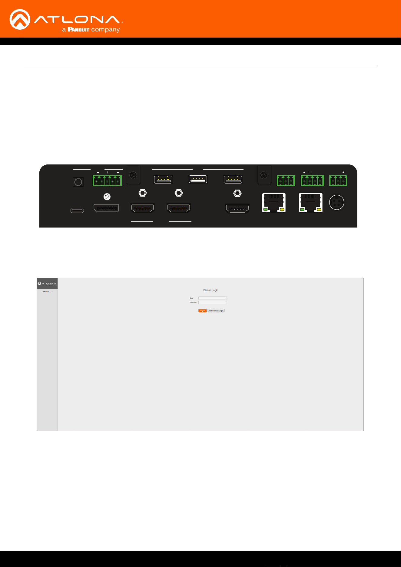
1. Launch a web browser.
2. In the address bar, type the IP address of the AT-UHD-SW-510W.
3. Enter the login credentials and click the Login button. The default credentials are listed below:
Username: admin
Password: Atlona
4. The Info page will be displayed, as shown on the next page.
Solution Setup and Conguration Guide
AT-UHD-SW-510W
6
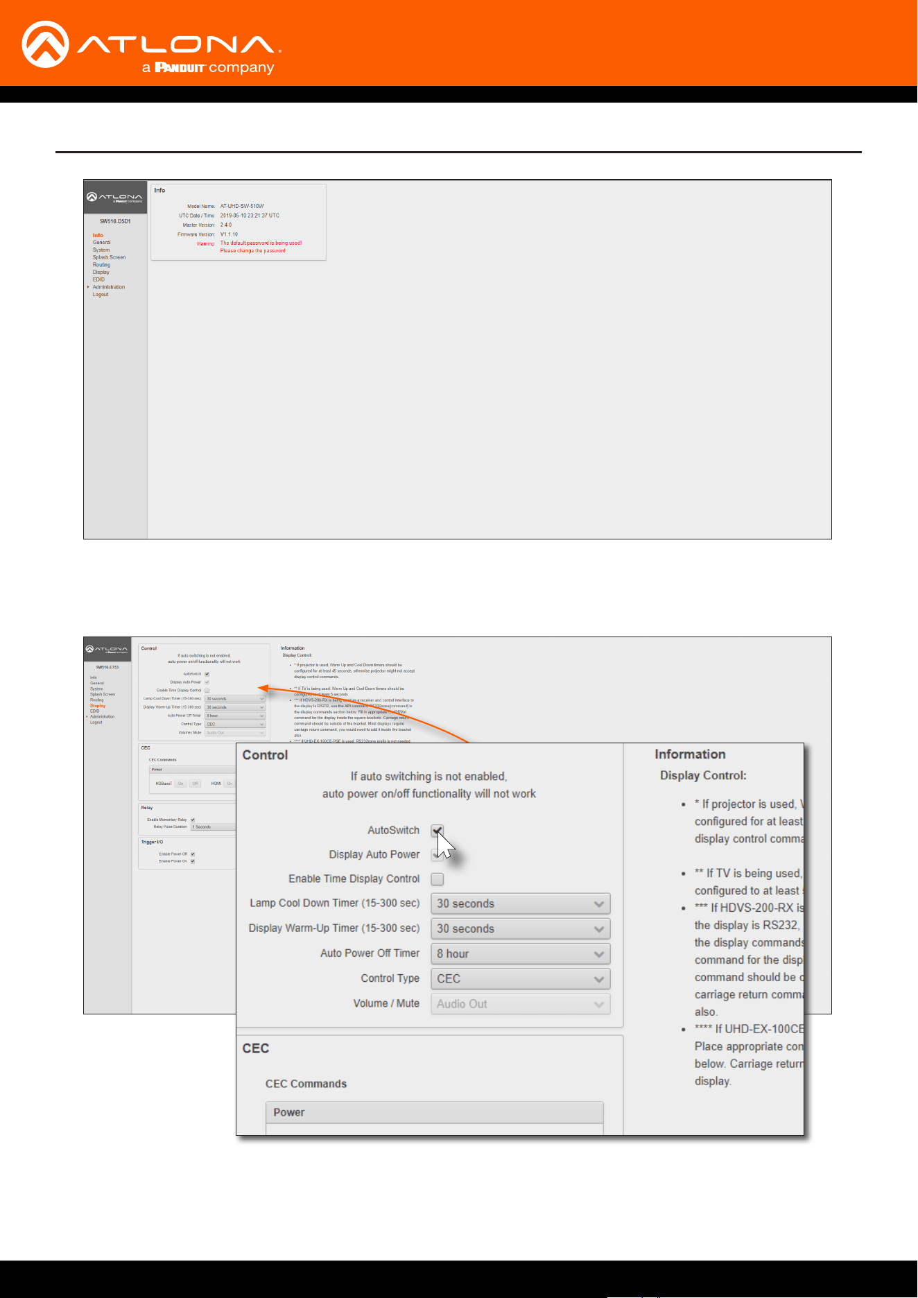
5. Click Display in the menu on the left side of the window.
6. Locate the AutoSwitch check box, under the Control window group.
Solution Setup and Conguration Guide
7. Click this check box to enable auto-switching. When auto-switch is enabled, a check mark will appear in this
box. To disable auto-switching, click the AutoSwitch check box again.
AT-UHD-SW-510W
7
Display Control
The following section cover display control using the following methods:
• CEC
• RS-232
• IP
CEC Control
CEC Control over HDMI
HDMI
AT-UHD-SW-510W
Display
USB-C
DP
HDMI 3
HDMI 4
BYOD
DISPLAY
INPUT
AT-UHD-SW-510W
Solution Setup and Conguration Guide
AT-UHD-SW-510W
USB-C
DP
HDMI 3
HDMI 4
BYOD
DISPLAY
INPUT
AT-UHD-SW-510W
LAN
DC 24V
HDBaseT OUT
HDMI OUTHDMI IN
DP IN
USB-C IN
2 3 4
1
RELAY
RS-232
TRIGGER I/O
MIRACASTWiFi AUX
AUDIO
OUT
L R
IN
USB
+
C1
COM
C2
RX
P
TX
+
+
USB
USB
USB
to display
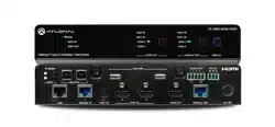
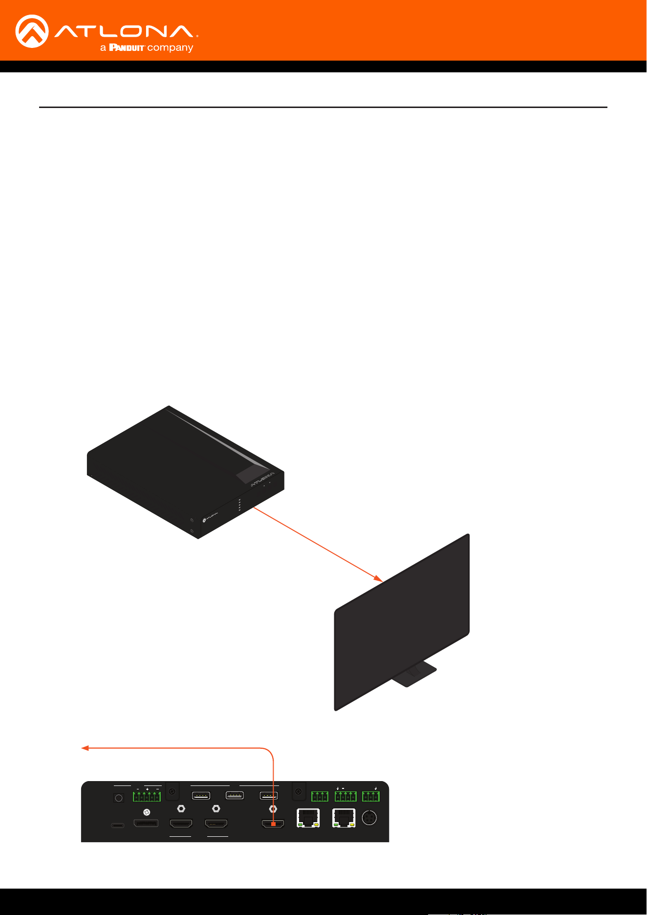
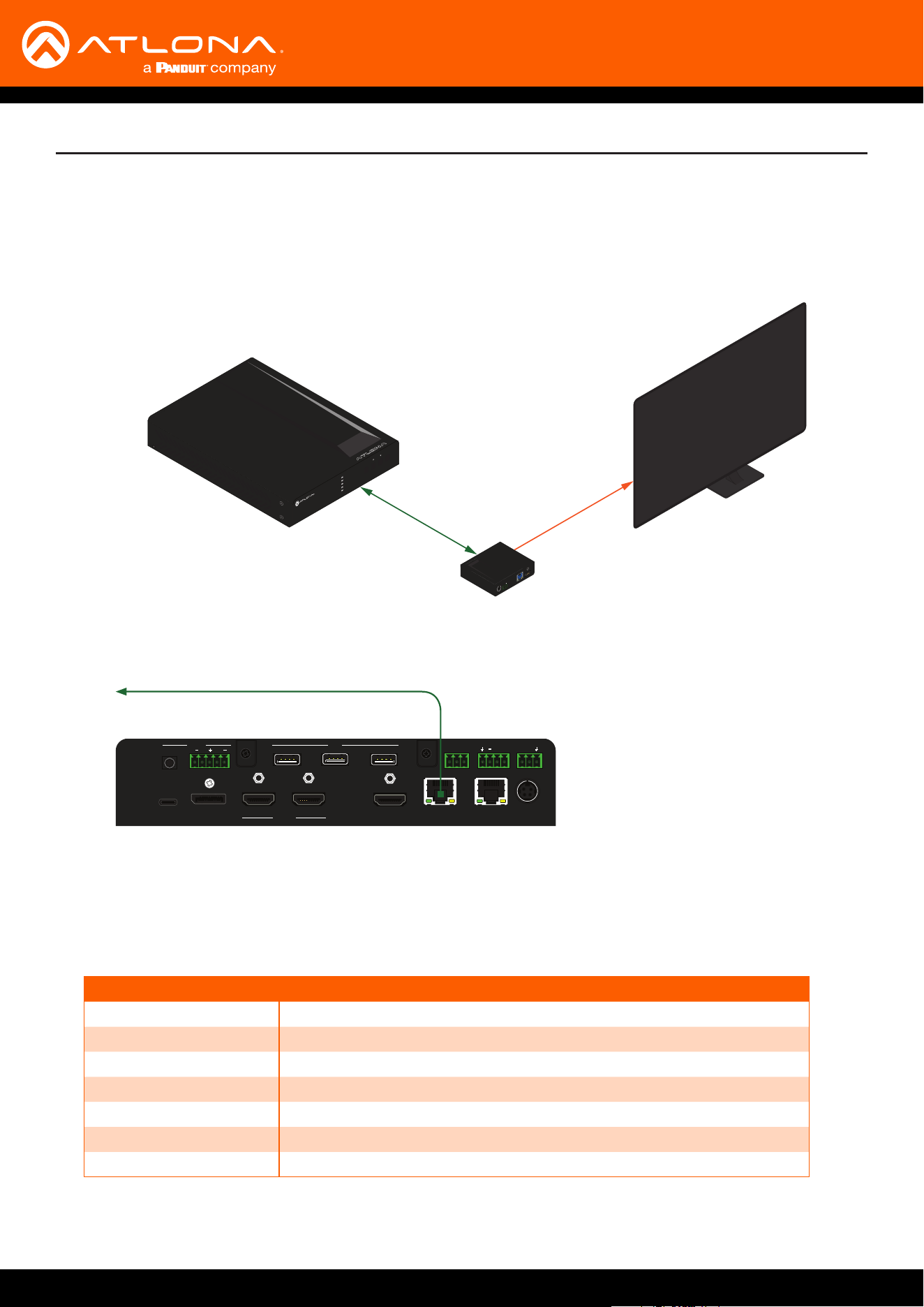
Consumer Electronics Control (CEC) is the simplest method when working with a consumer display. Note that the
display must have CEC enabled to receive CEC messages. CEC can be transmitted over HDMI and/or HDBaseT.
Note that if both connection methods are used, simultaneously, the same CEC messages will be transmitted over
both HDMI OUT and HDBaseT OUT ports.
a. Connect an HDMI cable from the HDMI OUT port on the AT-UHD-SW-510W to an HDMI input on the display
device.
AT-UHD-SW-510W
8
Solution Setup and Conguration Guide
CEC Control over HDBaseT
HDBaseT
HDMI
AT-UHD-SW-510W
AT-UHD-100CE-RX-PSE
Display
DC 48V RS-232 HDBaseT IN HDMI OUT
RXTX
USB-C
DP
HDMI 3
HDMI 4
BYOD
DISPLAY
INPUT
AT-UHD-SW-510W
AT-UHD-SW-510W
USB-C
DP
HDMI 3
HDMI 4
BYOD
DISPLAY
INPUT
AT-UHD-SW-510W
LAN
DC 24V
HDBaseT OUT
HDMI OUTHDMI IN
DP IN
USB-C IN
2 3 4
1
RELAY
RS-232
TRIGGER I/O
MIRACASTWiFi AUX
AUDIO
OUT
L R
IN
USB
+
C1
COM
C2
RX
P
TX
+
+
USB
USB
USB
to compatible receiver device
1. Enable CEC on the display device. Refer to the documentation for the display device. It should be noted that
dierent manufacturers will identify CEC with their own brand name. Refer to the table below.
Manufacturer CEC Designation
Hitachi HDMI-CEC
LG SIMPLINK
Philips EasyLink
Samsung AnyNet+
Sony BRAVIA Sync
Toshiba CE Link / REGZA Link
Visio HDMI-CEC
a. Connect a category cable (CAT-5e or better) from the HDBaseT OUT port on the AT-UHD-SW-510W to a
compatible receiver. The example below uses an AT-UHD-100CE-RX-PSE.
b. Connect an HDMI cable from the HDMI OUT port on the receiver to the HDMI input on the display device.
AT-UHD-SW-510W
9
Solution Setup and Conguration Guide
2. Launch a web browser.
3. In the address bar, type the IP address of the AT-UHD-SW-510W.
NOTE: If using AMS and the AT-UHD-SW-510W is running 2.4.0 or greater, click on the device within
AMS to access the web interface.
4. The Login page will be displayed. Enter the required credentials. The default credentials are shown below:
Username: admin
Password: Atlona
5. Click the Submit button or press the ENTER key on the keyboard.
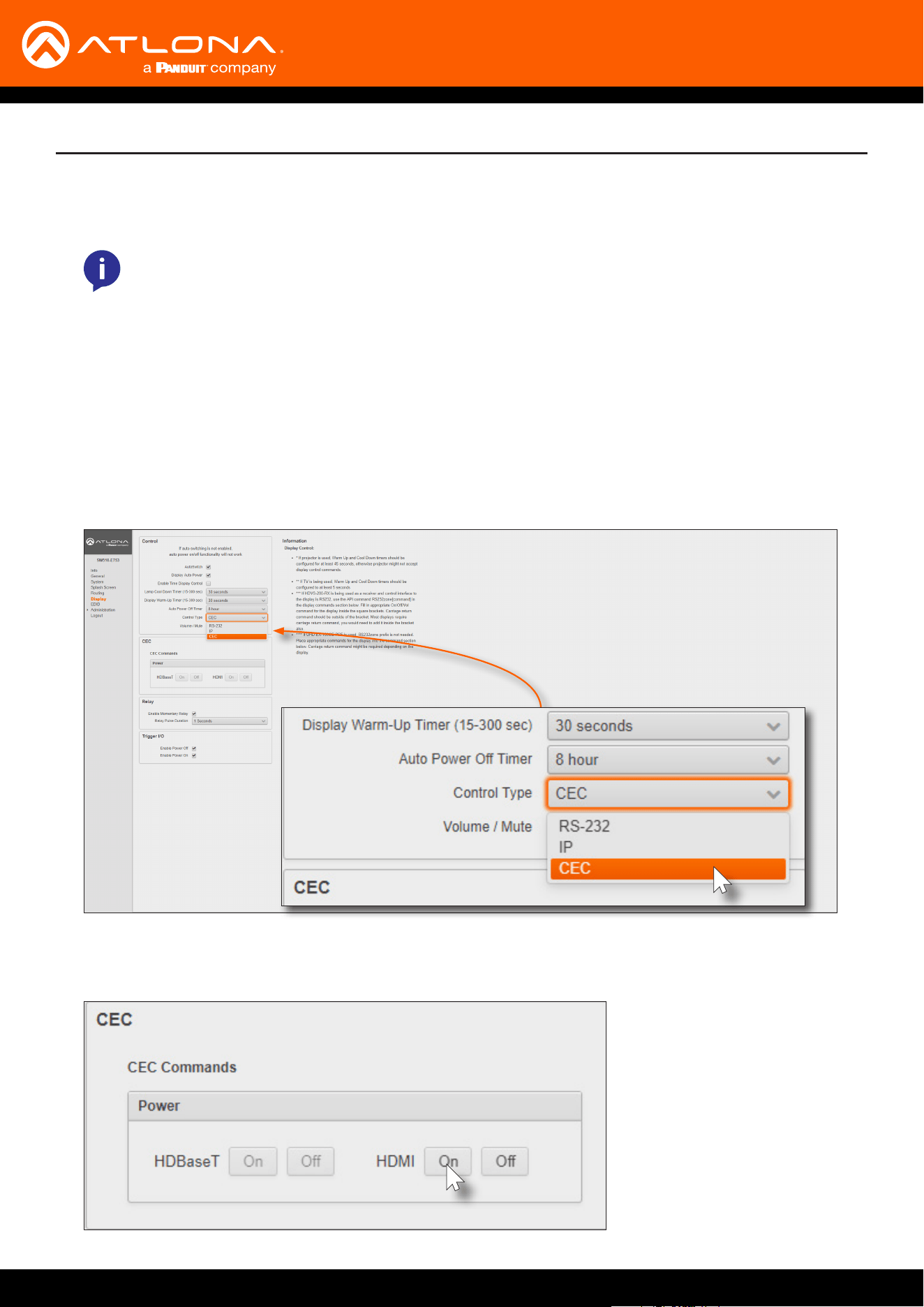
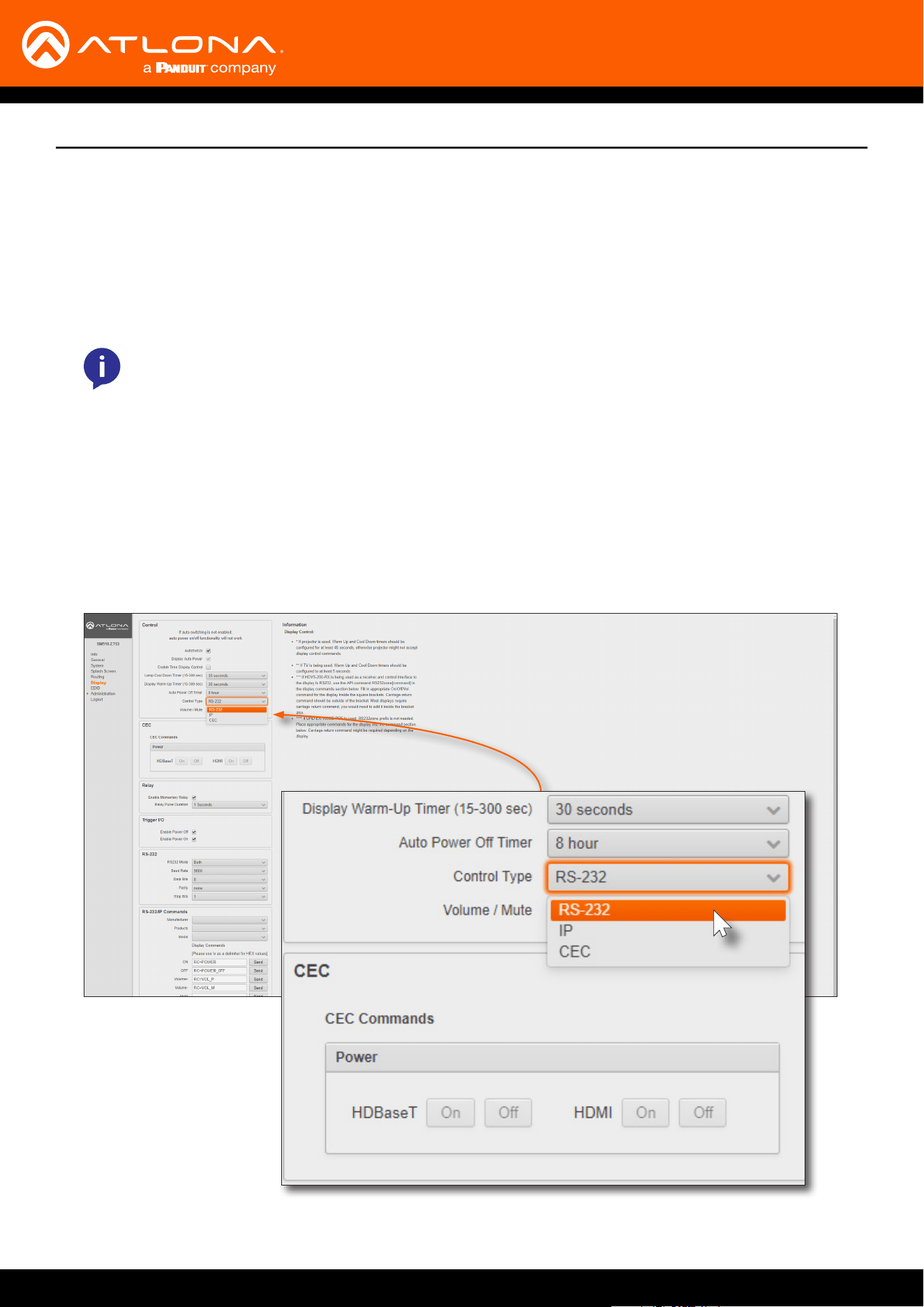
6. Click Display in the menu on the left side of the window.
7. Click the Control Type drop-down list and select CEC.
8. Under the CEC section, next to HDMI, test the power-on and power-o commands by clicking the ON and OFF
buttons, respectively. The display should power-on and power-o when clicking these buttons.

AT-UHD-SW-510W
10
Solution Setup and Conguration Guide
If the display does not respond, check the following:
• Verify that CEC is enabled on the display device.
• Verify the integrity of the HDMI cable. Try connecting a dierent HDMI cable between the AT-UHD-SW-510W
and the display device.
• Try connecting the HDMI cable to a dierent HDMI input on the display device.
Consumer Electronics Control (CEC): Atlona has conrmed proper CEC functionality with several current models of
Samsung, Panasonic, and Sony displays. However, it is not guaranteed that CEC will work with all displays. Many
manufacturers do not support the CEC “o” command, and older displays use proprietary commands. Atlona only
supports displays that use the CEC command structure dened in HDMI 1.2a. It is recommended that dealers re-
quest an evaluation product from Atlona, before designing a system using the CEC protocol. If this is not possible,
then other control methods will need to be considered, in order to control displays using Atlona products.
AT-UHD-SW-510W
11
Solution Setup and Conguration Guide
AT-UHD-SW-510W
RS-232 Control
RS-232
AT-UHD-SW-510W
Display
USB-C
DP
HDMI 3
HDMI 4
BYOD
DISPLAY
INPUT
AT-UHD-SW-510W
Display
AT-UHD-SW-510W
GND
GND
RxD
TxD
TxD
RxD
USB-C
DP
HDMI 3
HDMI 4
BYOD
DISPLAY
INPUT
AT-UHD-SW-510W
LAN
DC 24V
HDBaseT OUT
HDMI OUTHDMI IN
DP IN
USB-C IN
2 3 4
1
RELAY
RS-232
TRIGGER I/O
MIRACASTWiFi AUX
AUDIO
OUT
L R
IN
USB
+
C1
COM
C2
RX
P
TX
+
+
USB
USB
USB
to display
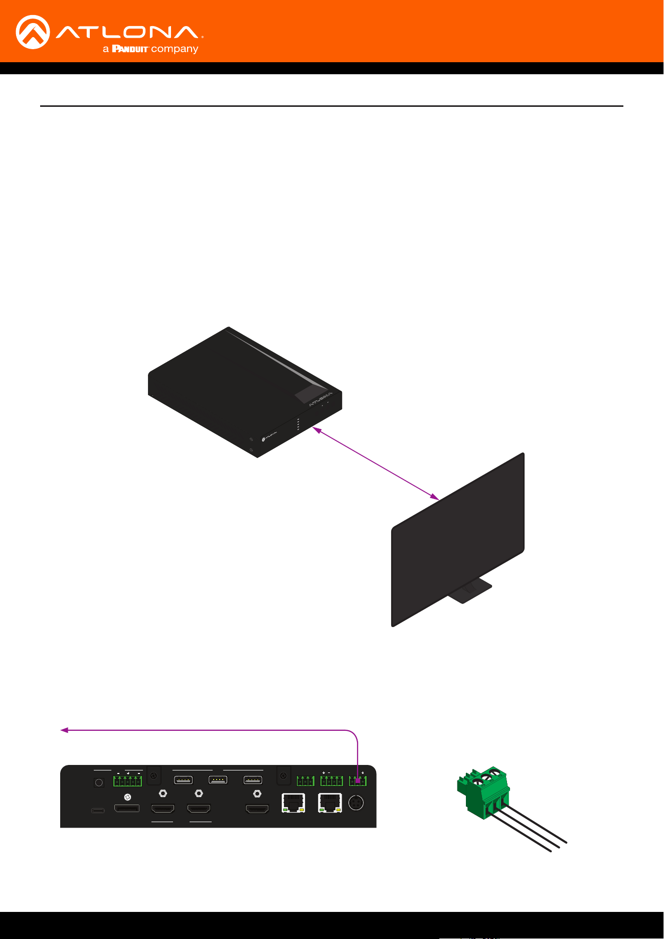
The AT-UHD-SW-510W can be connected directly to the display, using these ports, or a receiver, such as the AT-
UHD-100CE-RX-PSE can be used to extend these signals to a remote display, up to 330 feet (100 meters) away.
No external control system is required. This allows for convenient control of the display device from the location of
the source device.
Two RS-232 connection methods will be covered in this section:
• Controlling a Display from the AT-UHD-SW-510W
• Controlling a Display over HDBaseT
1. Connect the included 3-pin captive screw connector from the RS-232 port on the AT-UHD-SW-510W to the RS-
232 port on the display device. The included 3-pin captive screw connector should be wired as shown.
Controlling a Display from the AT-UHD-SW-510W
AT-UHD-SW-510W
12
Solution Setup and Conguration Guide
AT-UHD-EX-100CE-TX-PSE
HDBaseT (up to 330 feet / 100 meters)
AT-UHD-SW-510W
1. Connect an Ethernet cable from the HDBaseT OUT port on the AT-UHD-SW-510W to the HDBaseT IN port on
the AT-UHD-EX-100CE-RX-PSE.
USB-C
DP
HDMI 3
HDMI 4
BYOD
DISPLAY
INPUT
AT-UHD-SW-510W
LAN
DC 24V
HDBaseT OUT
HDMI OUTHDMI IN
DP IN
USB-C IN
2 3 4
1
RELAY
RS-232
TRIGGER I/O
MIRACASTWiFi AUX
AUDIO
OUT
L R
IN
USB
+
C1
COM
C2
RX
P
TX
+
+
USB
USB
USB
FWLAN LINK
POWER
AT-UHD-EX-100CE-RX-PSE
DC 48V RS-232 HDBaseT IN HDMI OUT
RX TX
IMPORTANT: The AT-UHD-SW-510W does not supply PoE over HDBaseT. The receiver must be
powered using a local power supply.
HDBaseT
RS-232
AT-UHD-SW-510W
AT-UHD-100CE-RX-PSE
Display
DC 48V RS-232 HDBaseT IN HDMI OUT
RXTX
USB-C
DP
HDMI 3
HDMI 4
BYOD
DISPLAY
INPUT
AT-UHD-SW-510W
2. Connect the included 3-pin captive screw connector from the RS-232 port on the AT-UHD-EX-100CE-RX-PSE to
the RS-232 port on the display device. The included 3-pin captive screw connector should be wired as shown.
AT-UHD-EX-100CE-TX-PSE
FWLAN LINK
POWER
AT-UHD-EX-100CE-RX-PSE
DC 48V RS-232 HDBaseT IN HDMI OUT
RX TX
to display
Display
AT-UHD-EX-100CE-TX-PSE
GND
GND
RxD
TxD
TxD
RxD
Controlling a Display over HDBaseT
AT-UHD-SW-510W
13
Solution Setup and Conguration Guide
1. Launch a web browser.
2. In the address bar, type the IP address of the AT-UHD-SW-510W.
RS-232 Control Conguration
Once the AT-UHD-SW-510W is connected, either directly or using an extender, use the following procedure to
congure RS-232 control.
NOTE: If using AMS and the AT-UHD-SW-510W is running 2.4.0 or greater, click on the device within
AMS to access the web interface.
3. The Login page will be displayed. Enter the required credentials. The default credentials are shown below:
Username: admin
Password: Atlona
4. Click the Submit button or press the ENTER key on the keyboard.
5. Click Display in the menu on the left side of the window.
6. Click the Control Type drop-down list and select RS-232.
AT-UHD-SW-510W
14
NOTE: If Local RS232 Only or Both is selected, then the AT-UHD-SW-510W cannot be controlled
from a controlled system using RS-232.
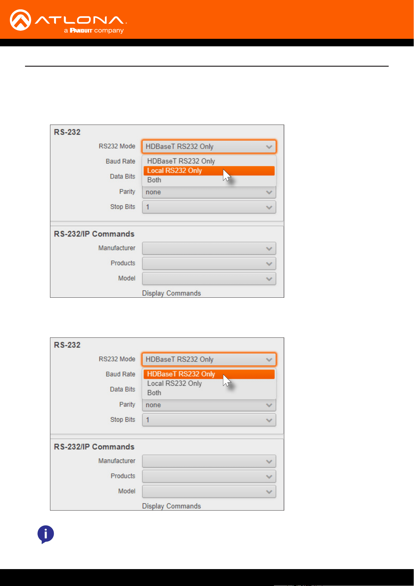
7. Scroll down and locate the RS-232 section.
Solution Setup and Conguration Guide
a. If the RS-232 cable is connected directly from the AT-UHD-SW-510W to the display, then click the RS232
Mode drop-down list and select Local RS232 Only.
b. If the RS-232 cable is connected to a remote extender, over HDBaseT, then click the RS232 Mode drop-
down list and select HDBaseT RS232 Only.
AT-UHD-SW-510W
15
Solution Setup and Conguration Guide
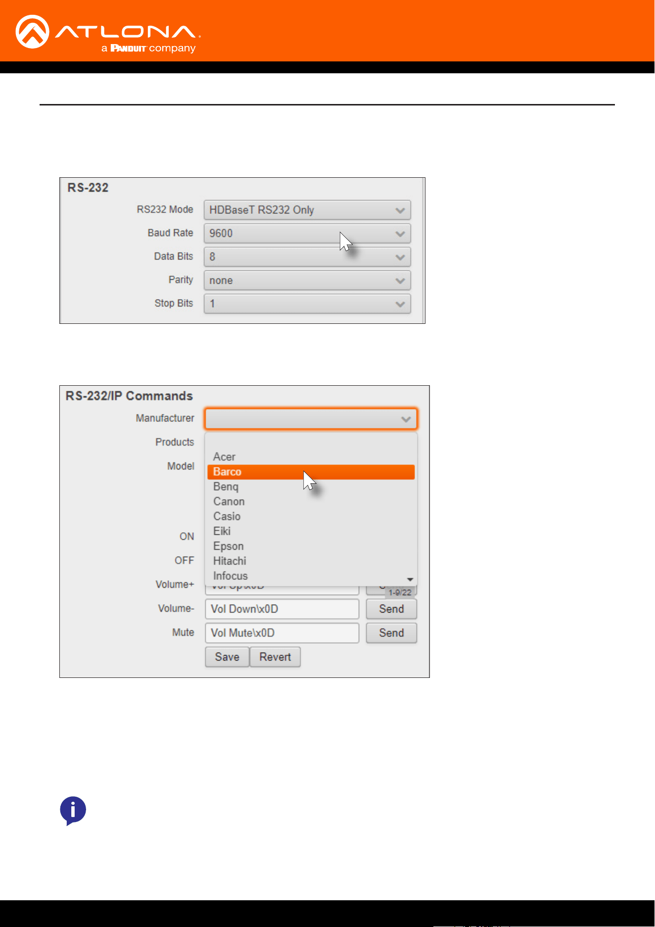
9. Scroll down to the RS-232/IP Commands section and click the Manufacturer drop-down list to select the
manufacturer of the device that is being controlled.
10. Continue ne-tuning the device selection by clicking the Products and Model drop-down lists. Once all elds
have been set to the proper values, the AT-UHD-SW-510W will populate the ON, OFF, Volume+, Volume-, and
Mute elds with the commands used by that device.
Refer to the next page for example command strings.
8. Click the Baud Rate, Data Bits, Parity, and Stop Bits drop-down list to set the values required by the control
system. If these values do not match the RS-232 settings of the control system, then RS-232 control will not
function properly.
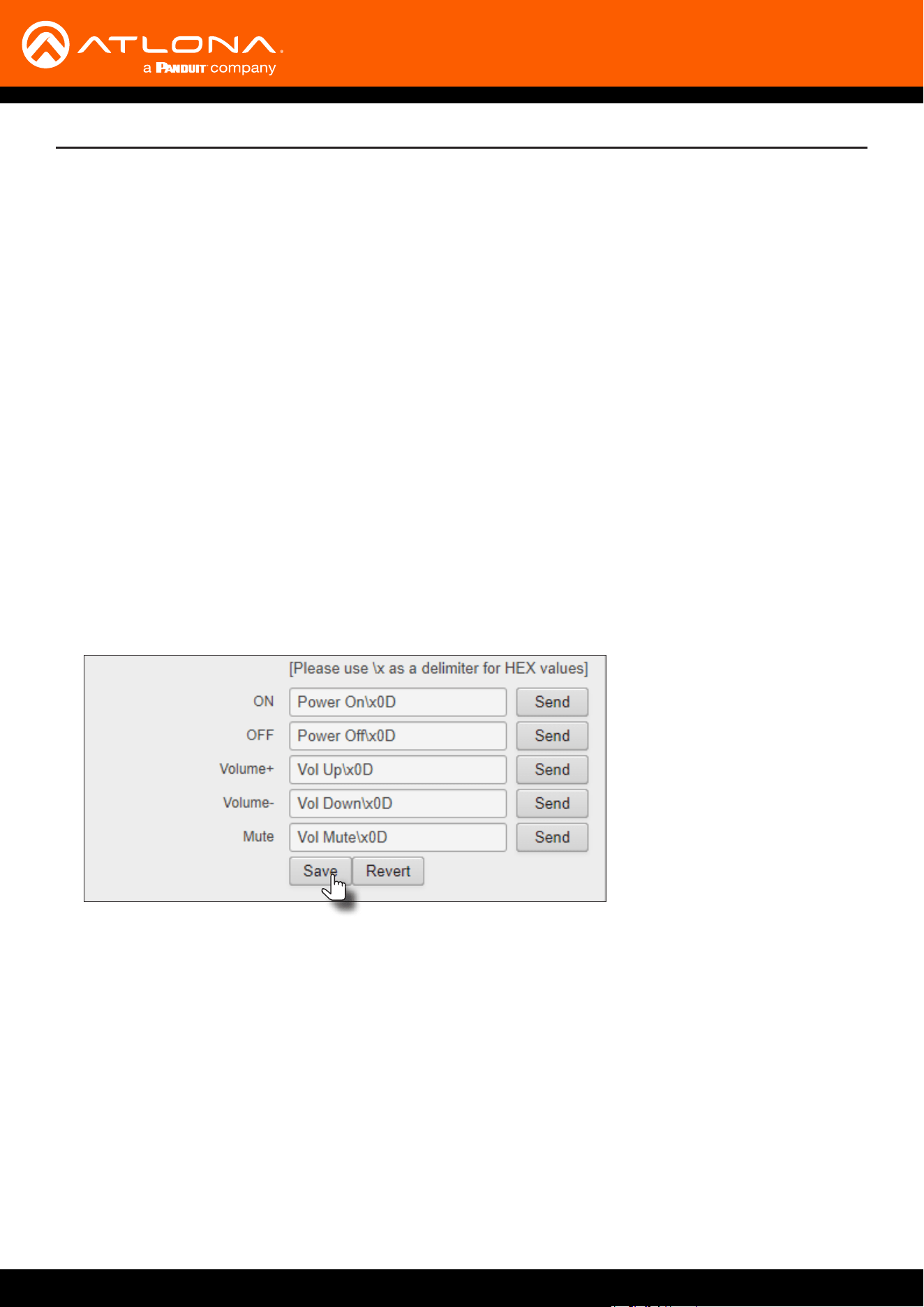
NOTE: If the manufacturer/model is not listed in the drop-down lists, then commands for the ON,
OFF, Volume+, Volume-, and Mute elds can be entered manually. Consult the User Manual for the
sink device to obtain the correct command format.
AT-UHD-SW-510W
16
Solution Setup and Conguration Guide
HEX Command Strings
ASCII Command Strings
a. An example hexadecimal power-on command for a display might be:
\xBE\xEF\x03\x06\x00\xBA\xD2\x01\x00\x00\x60\x01\x00\x0D
Consult the display documentation for the correct command strings.
b. Make sure the command string is terminated correctly. In most cases, a CR (carriage return) should be
specied. In the example above, “\x0D” is the hexadecimal value for a carriage return.
a. An example ASCII power-on command for a display might be:
PWOFF\x0D
Note the use of the “\x0D” delimter in the command string. This must be used to terminate the
command string.
11. Click the Send button to test each command.
12. Click the Save button to commit changes.
AT-UHD-SW-510W
17
USB-C
DP
HDMI 3
HDMI 4
BYOD
DISPLAY
INPUT
AT-UHD-SW-510W
LAN
DC 24V
HDBaseT OUT
HDMI OUTHDMI IN
DP IN
USB-C IN
2 3 4
1
RELAY
RS-232
TRIGGER I/O
MIRACASTWiFi AUX
AUDIO
OUT
L R
IN
USB
+
C1
COM
C2
RX
P
TX
+
+
USB
USB
USB
Solution Setup and Conguration Guide
Conguring IP Control
HDBaseT
Ethernet
AT-UHD-SW-510W
AT-UHD-100CE-RX-PSE
Display
DC 48V RS-232 HDBaseT IN HDMI OUT
RXTX
USB-C
DP
HDMI 3
HDMI 4
BYOD
DISPLAY
INPUT
AT-UHD-SW-510W
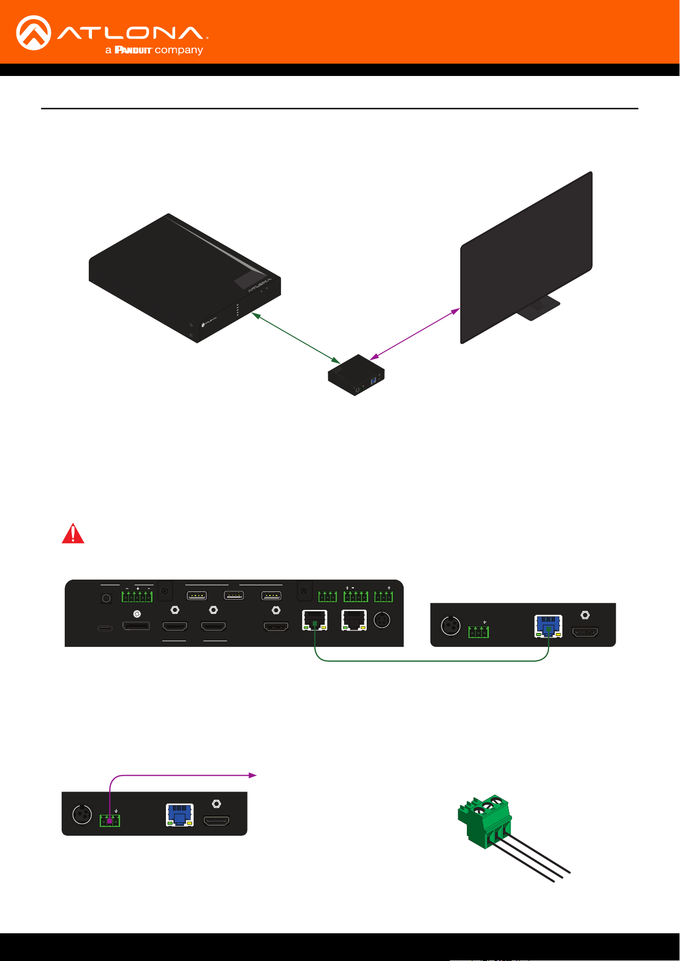
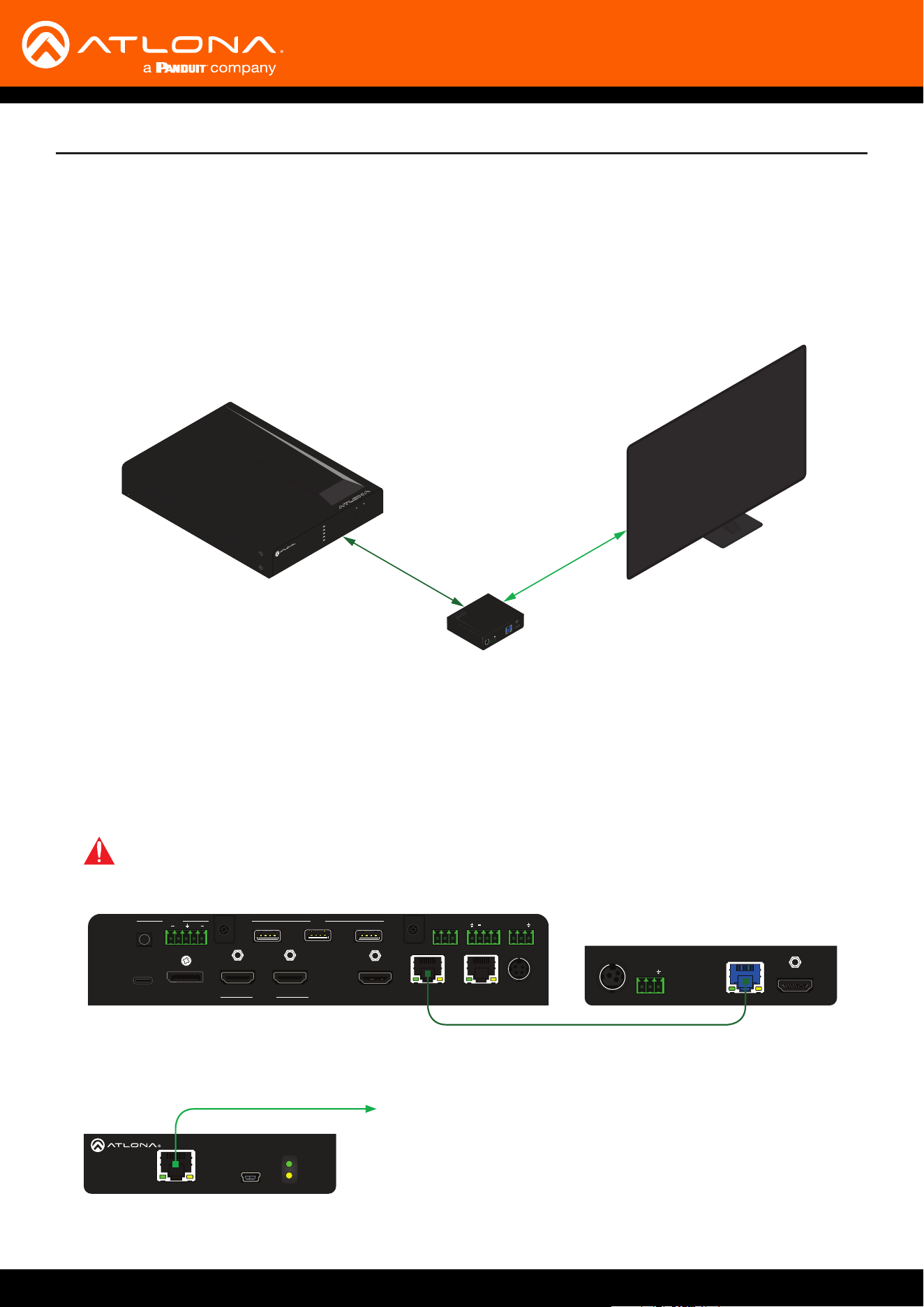
Display control can also be performed over IP. The steps are similar to the HDBaseT RS-232 setup, except that an
Ethernet cable is connected between the LAN port on the extender and the display device.
The following example shows how to extend IP control, using the AT-UHD-100CE-RX-PSE.
AT-UHD-EX-100CE-TX-PSE
AT-UHD-SW-510W
1. Connect a category cable from the HDBaseT OUT port on the AT-UHD-SW-510W to the HDBaseT IN port on
the AT-UHD-EX-100CE-RX-PSE.
FWLAN LINK
POWER
AT-UHD-EX-100CE-RX-PSE
DC 48V RS-232 HDBaseT IN HDMI OUT
RX TX
IMPORTANT: The AT-UHD-SW-510W does not supply PoE over HDBaseT. The receiver must be
powered using a local power supply.
AT-UHD-EX-100CE-TX-PSE
FWLAN LINK
POWER
AT-UHD-EX-100CE-RX-PSE
DC 48V RS-232 HDBaseT IN HDMI OUT
RX TX
to display
2. Connect an Ethernet cable from the LAN port on the AT-UHD-EX-100CE-RX-PSE to the Ethernet port on the
display device.
AT-UHD-SW-510W
18
3. Launch a web browser.
4. In the address bar, type the IP address of the AT-UHD-SW-510W.
Solution Setup and Conguration Guide
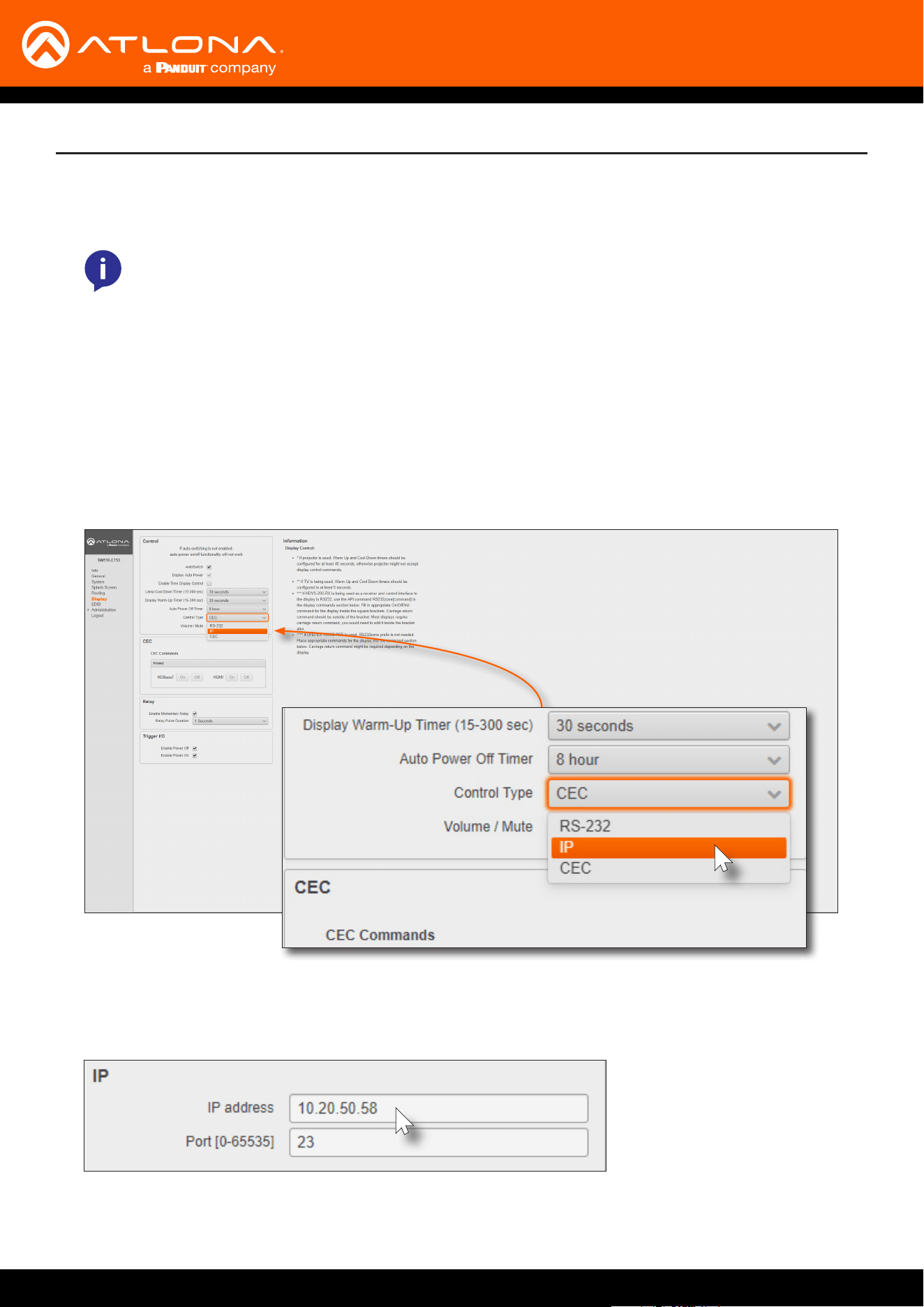
9. Locate the IP section and enter the IP address, of the device that is being controlled, in the IP address eld.
10. Enter the port number in the Port eld. Valid port numbers can be from 0 to 65535.
11. Refer to step 9, on page 13, to complete the conguration process.
NOTE: If using AMS and the AT-UHD-SW-510W is running 2.4.0 or greater, click on the device within
AMS to access the web interface.
5. The Login page will be displayed. Enter the required credentials. The default credentials are shown below:
Username: admin
Password: Atlona
6. Click the Submit button or press the ENTER key on the keyboard.
7. Click Display in the menu on the left side of the window.
8. Click the Control Type drop-down list and select IP.
AT-UHD-SW-510W
19
Solution Setup and Conguration Guide
The AT-UHD-SW-510W can be congured to automatically power-on or power-o a display during specied times
and days of the week. Time must be specied in Universal Coordinated Time (UTC) format. Note that discrete
calendar dates cannot be specied.
1. Login to the web GUI and click System from the menu bar on the left.
2. Click the AutoSwitch check box to enable auto-switching. When enabled, a check mark will appear in this box.
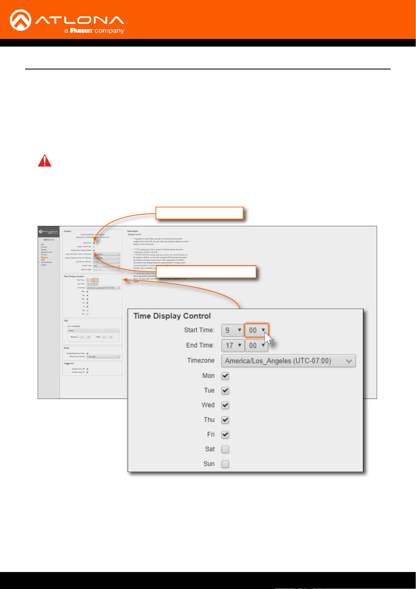
5. Click drop-down lists, next to Start Time, to set the hour and minute when the display will be powered-on.
Time is specied in 24-hour format.
6. Click the End Time drop-down lists, for both hour and minute, to specify the display power-o time. Time is
specied in 24-hour format.
7. Click the Timezone drop-down list to set the proper time zone.
8. Click the desired checkbox(s) to specify which day(s) that the unit will power-on and power-o the connected
display.
Display Auto Power
Enable Time Display Control
Scheduling Display Operation Times
IMPORTANT: Auto-switching must be enabled in order for auto-powering to function.
3. Click the Display Auto Power check box. When enabled, a check mark will appear in this box.
4. Click the Enable Time Display Control check box.
AT-UHD-SW-510W
20
Solution Setup and Conguration Guide
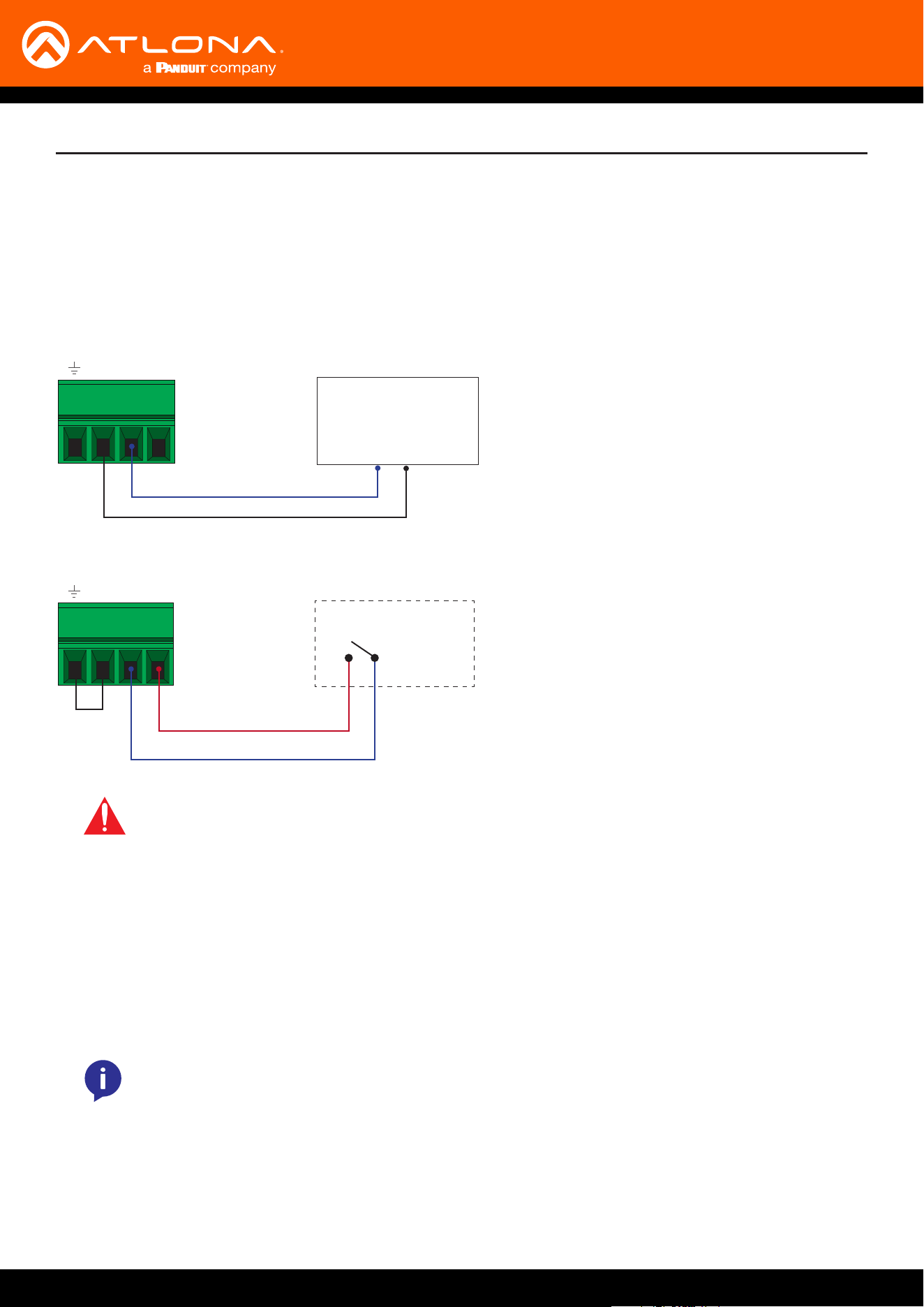
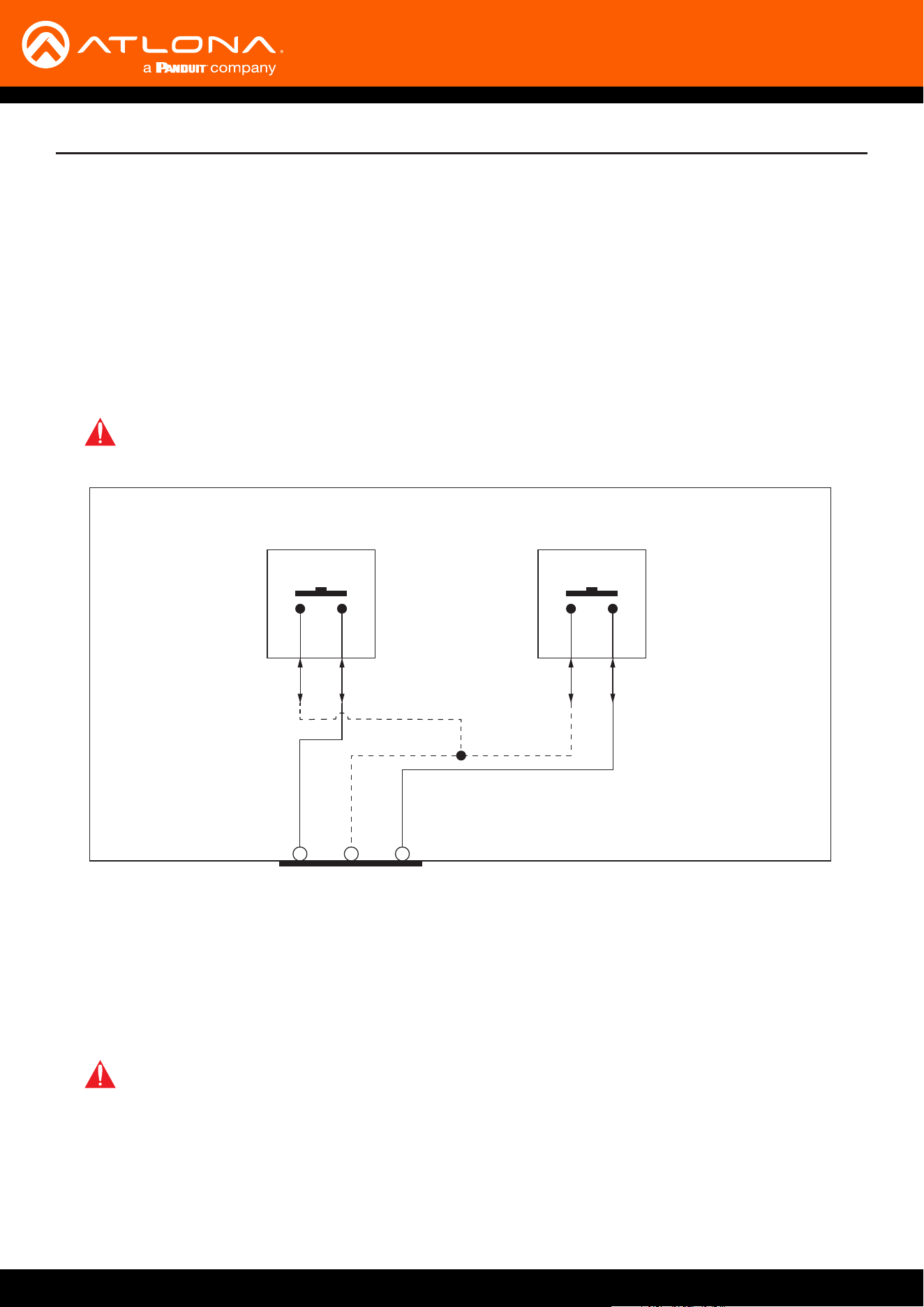
The TRIGGER I/O port, on the rear panel, allows voltage-controlled devices, such as an occupancy sensor, to be
connected to the AT-UHD-SW-510W. Use the included 4-pin captive screw connector to connect the device.
The trigger voltage range is 3 V to 30 V DC.
Conguration of the TRIGGER I/O port can be done through the web GUI or using API commands. Refer to the
Application Programmers Interface, on the Atlona AT-UHD-SW-510W product web page, for more information.
Passive sensor
Powered sensor
Common (Set LOW)
Control (Set HIGH)
Powered sensor
30 V (max.)
- + P
Control (Set HIGH)
+12 V DC
Passive sensor
- + P
IMPORTANT: Some occupancy sensors require 24 V DC instead of 12 V DC. In these cases, an
external power supply will be required in order to power the sensor.
1. Launch a web browser.
2. In the address bar, type the IP address of the AT-UHD-SW-510W.
Trigger Port
Wiring
Conguration using the Web GUI
NOTE: If using AMS and the AT-UHD-SW-510W is running 2.4.0 or greater, click on the device within
AMS to access the web interface.
3. The Login page will be displayed. Enter the required credentials. The default credentials are shown below:
Username: admin
Password: Atlona
AT-UHD-SW-510W
21
Solution Setup and Conguration Guide
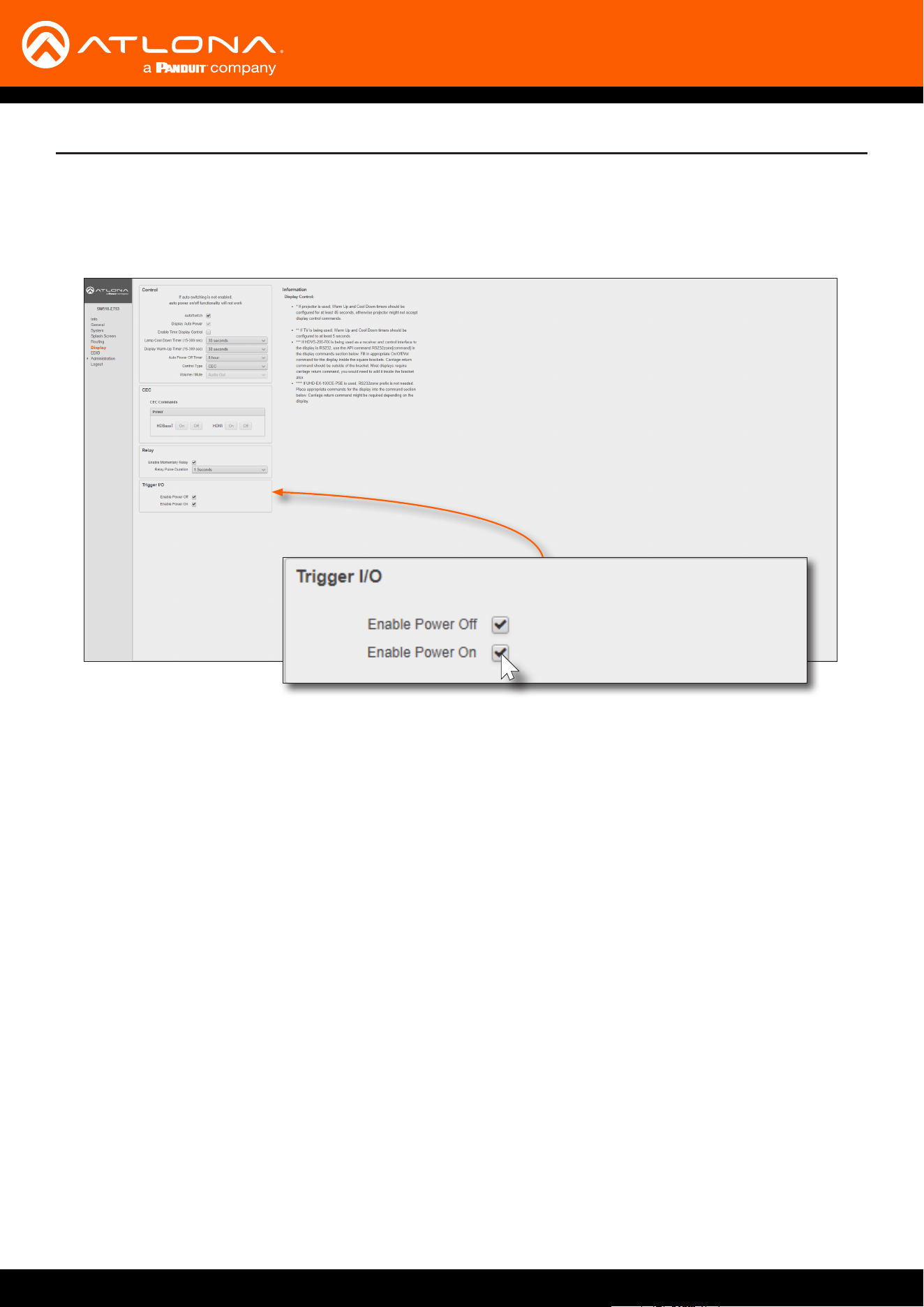
4. Click the Submit button or press the ENTER key on the keyboard.
5. Click Display in the menu on the left side of the window.
6. Locate the Trigger I/O section.
7. Click the desired checkboxes for the desired operation. By default, both Enable Power O and Enable Power
On are checked (enabled).
AT-UHD-SW-510W
22
Relay Port
The AT-UHD-SW-510W provides a RELAY port, which provides a control interface for screens, curtains, and or other
devices.
Solution Setup and Conguration Guide
COMC1 C2
Relay 1 (up)
AT-UHD-SW-510W
Relay 2 (down)
NONO
The RELAY connector is wired to a pair of single-pole single-throw (SPST) relays, as shown below, providing two
independent switches and a common (COM) connection. The relay is designed to work with devices that conform to
standard Low Voltage Control (LVC). The AT-UHD-SW-510W software allows only a single relay switch to be enabled
at any time.
The AT-UHD-SW-510W can be programmed through the built-in web GUI to pulse the C2 contact when the
AT-UHD-SW-510W is active and then pulse the C1 contact when the AT-UHD-SW-510W becomes inactive.
Pulse length can also be congured using the web GUI. Refer to the next page for more information.
IMPORTANT: The maximum voltage and current for the RELAY connector is 48 V / 1 A DC.
IMPORTANT: When the AT-UHD-SW-510W is powered-on or rebooted, both C1 and C2 are will be
in the Normally Open (NO) state.
Wiring
Operation
AT-UHD-SW-510W
23
Conguration of the RELAY port can be done through the web GUI or using API commands. Refer to the Application
Programmers Interface, on the Atlona AT-UHD-SW-510W product web page, for more information.
1. Launch a web browser.
2. In the address bar, type the IP address of the AT-UHD-SW-510W.
Conguration using the Web GUI
NOTE: If using AMS and the AT-UHD-SW-510W is running 2.4.0 or greater, click on the device within
AMS to access the web interface.
3. The Login page will be displayed. Enter the required credentials. The default credentials are shown below:
Username: admin
Password: Atlona
4. Click the Submit button or press the ENTER key on the keyboard.
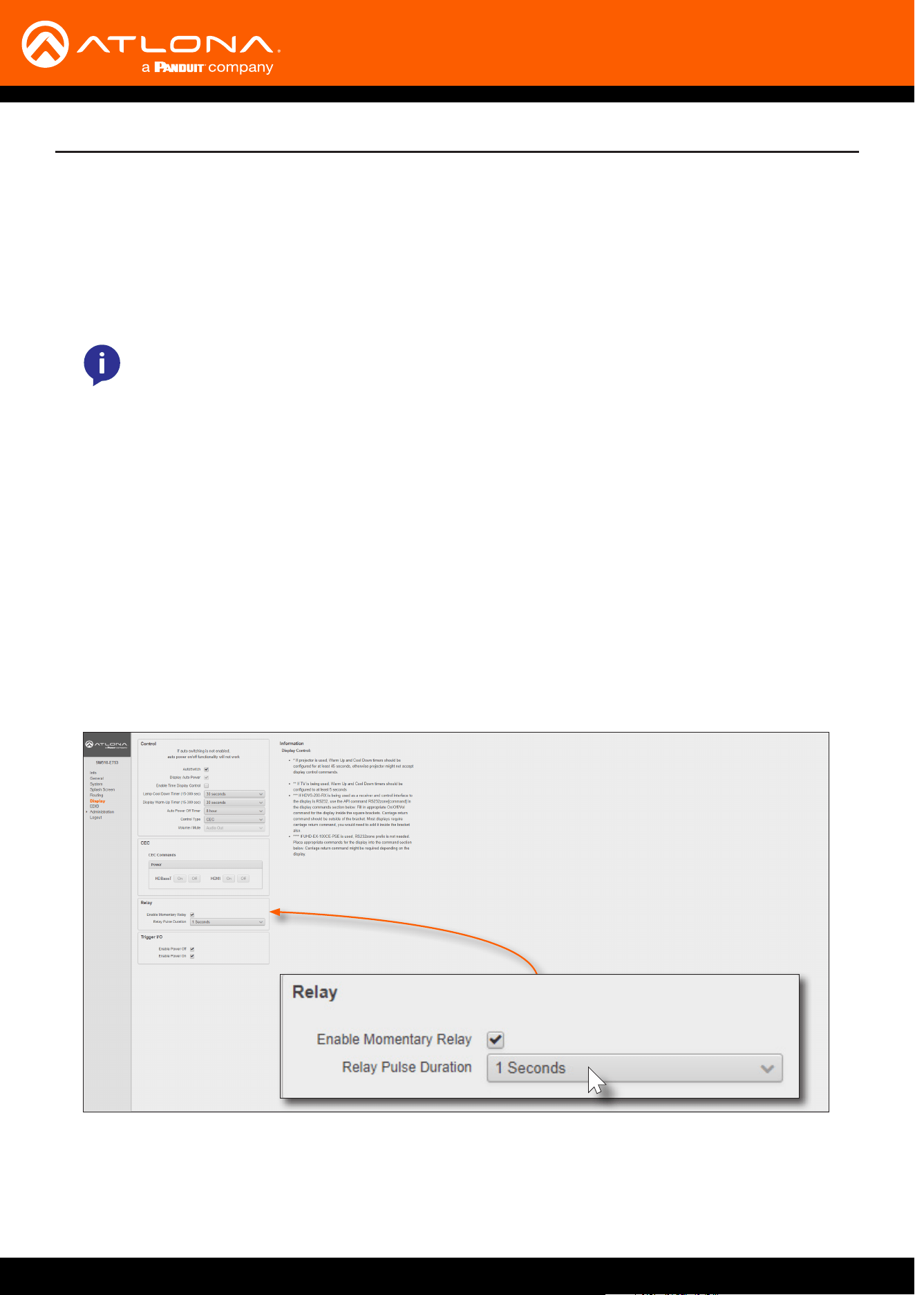
5. Click Display in the menu on the left side of the window.
6. Locate the Relay section.
7. Click the Enable Momentary Relay check box to enable relay operation.
8. Click the Relay Pulse Duration drop-down list and select the desired duration. Note that some external devices
may not recognize pulse durations less than 1 second. In this case, it may be necessary to select a larger time
interval.
Solution Setup and Conguration Guide

© 2019 Atlona Inc. All rights reserved. “Atlona” and the Atlona logo are registered trademarks of Atlona Inc. All other brand names and trademarks or registered trademarks are the property of their respective owners. Pricing, specications and
availability subject to change without notice. Actual products, product images, and online product images may vary from images shown here.
Toll free US International
atlona.com • 877.536.3976 • 41.43.508.4321