1
Installation Guide
AT-PRO5-MX810
4K HDR HDMI
Matrix Switcher with SDVoE Extension Outputs
AT-PRO5-MX810
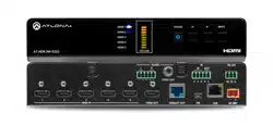
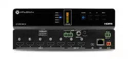
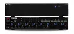
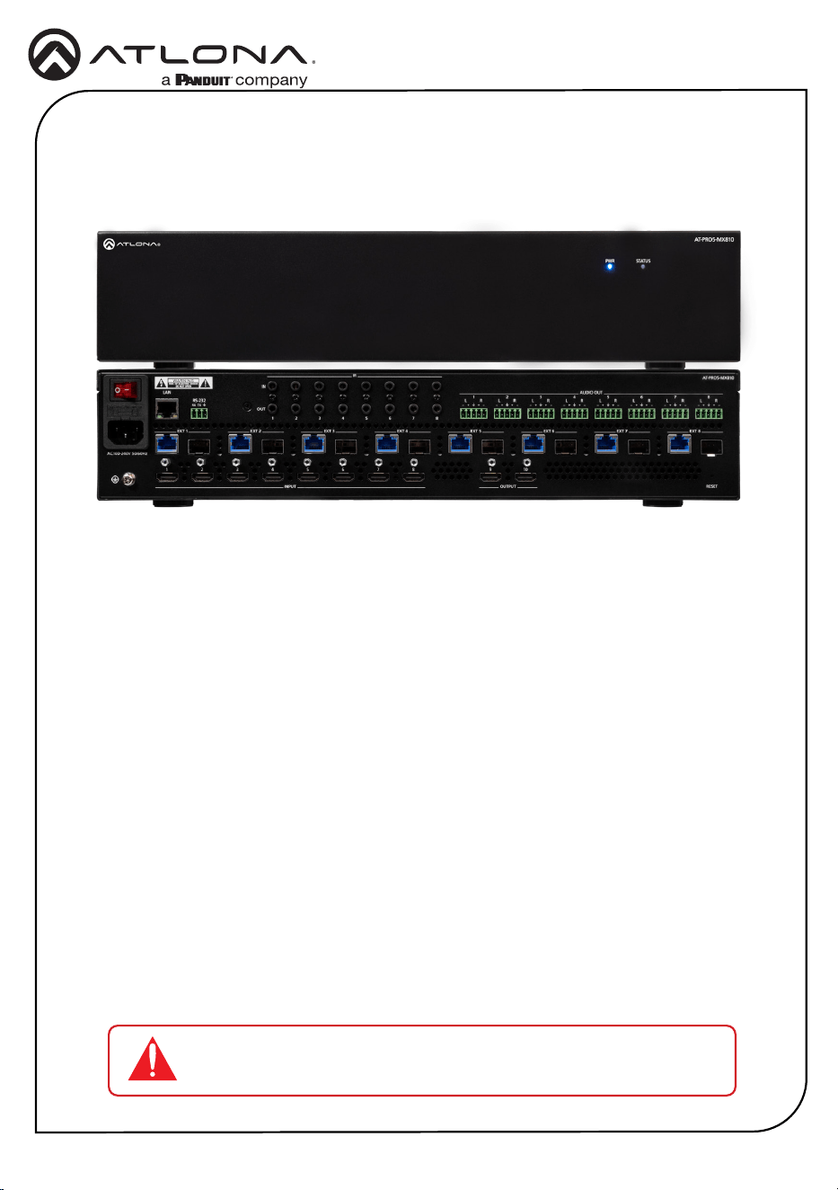
The Atlona AT-PRO5-MX810 is an 8x10 matrix switcher with eight HDMI
®
inputs, two HDMI
outputs, and eight AV extension outputs with SDVoE
®
10GbE connectivity for ultra-high denition
video and audio delivery to an Atlona AT-PRO5-101-SC-RX or AT-PRO5-101-RX receiver. Part of
the PRO5 Series, this matrix switcher is HDCP 2.3 compliant, and supports 4K/60 4:4:4 and HDR
at HDMI data rates up to 18 Gbps. Each SDVoE extension output includes an RJ45 port, and
an SFP+ cage for copper or ber-optic connectivity to transmit video, embedded audio, Gigabit
Ethernet, and RS-232 and IR control signals to the receiver. The RJ45 port allows extension up to
330 feet (100 meters) over CAT6a UTP cable, along with PoE for powering the receiver, while the
SFP+ cage can be used with a compatible ber optic module to extend from 38 meters up to 10
kilometers over ber optic cable. Video processing is available in the PRO5-101-SC-RX scaling
receivers, including 4K video upscaling and downscaling with frame rate conversion, and video
wall processing. This HDMI to SDVoE matrix switcher is equipped with a comprehensive host
of audio and control system integration features, making it ideal for a wide range of commercial
applications requiring multi-zone AV distribution with long-distance signal extension.
1 x AT-PRO5-MX810
1 x 3-pin captive screw connector
8 x 5-pin captive screw connectors
1 x AC power cord
1 x Insert w/ QR code
Package Contents
IMPORTANT: Visit https://www.atlona.com/product/at-pro5-mx810 for
the latest rmware updates and User Manual.

2
Installation Guide
AT-PRO5-MX810
1 PWR
LED will be red while the unit is booting
and blue when operating normally. Refer
to Front Panel LED Indicators (page 5)
for more information.
2 STATUS
LED will be blue when the unit is
operating normally. Refer to Front Panel
LED Indicators (page 5) for more
information.
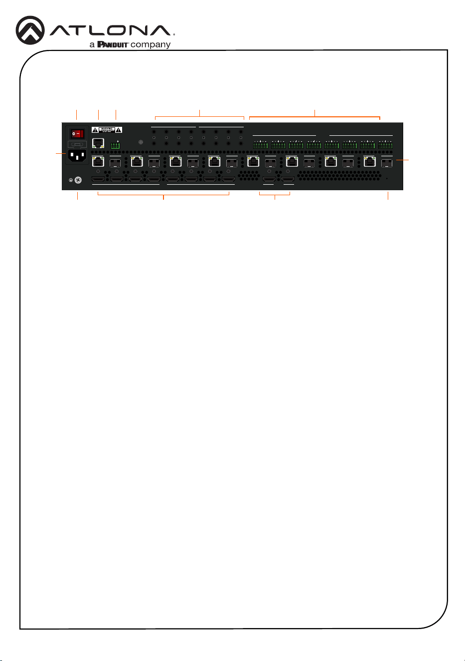
Front Panel Descriptions
1 2
AT-PRO5-MX810
PWR STATUS
RESET
87654321
1
OUT
IN
RS-232
LAN
RX TX
2 3 4
IR
5 6 7 8
L R
OUTPUTINPUT
10987654321
EXT 6EXT 5EXT 4EXT 3EXT 2EXT 1
AC100-240V 50/60Hz
EXT 7
AUDIO OUT
EXT 8
L R L R L R L R L R L R L R
3
Installation Guide
AT-PRO5-MX810
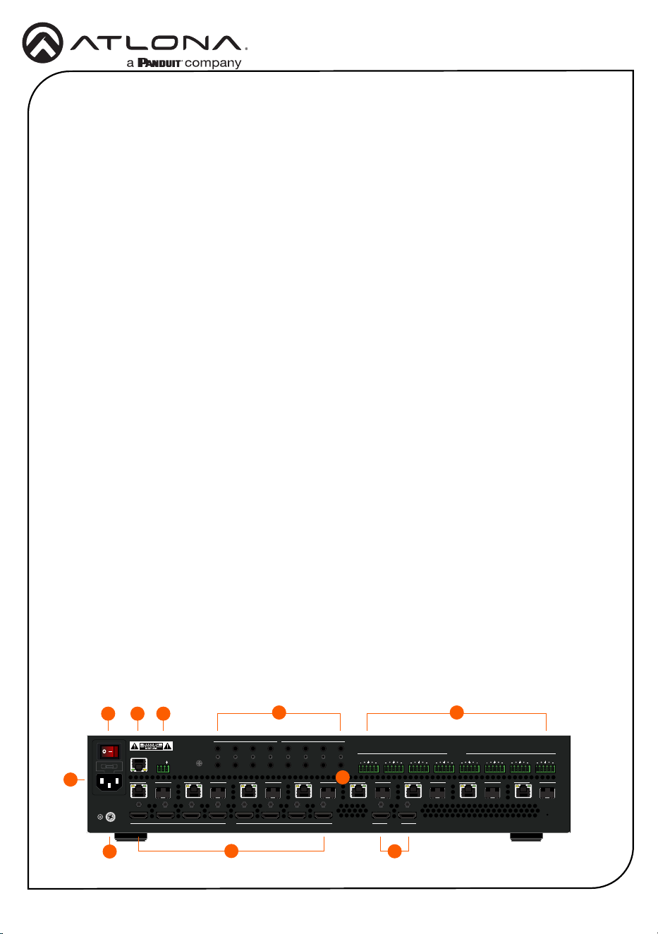
Rear Panel Descriptions
1 Power Switch
Turns the AT-PRO5-MX810 on or o.
Press the side of the switch labeled “I” to
power-on the unit. Press the side of the
switch labeled “O” to power-o the unit.
2 IEC Connector
Connect the included power cord from
this power receptacle to an available
grounded wall outlet.
3 Chassis Ground
Provides a common return path for
electric current and a safety feature to
prevent electric shock.
4 LAN
Connect an Ethernet cable from this port
to the network.
5 RS-232
Connect the included 3-pin captive screw
connector to this port.
6 INPUT
Connect an HDMI cable from each of
these ports to a HD/UHD source.
7 IR
This bank of ports provide both IR inputs
and outputs. Connect 3.5 mm jacks to
these ports.
8 OUTPUT
Connect an HDMI cable from each
of these ports to a display, such as a
condence monitor.
9 AUDIO OUT
Connect the included 5-pin captive screw
connectors from these port to an amplier.
10 RESET
Press this button to perform a factory-
reset of the AT-PRO5-MX810.
11 EXT 1 - EXT 8
Connect these outputs to the AT-PRO5-
101-SC-RX scaling receiver or AT-PRO5-
101-RX receiver. RJ45 ports provide
extension up to 330 feet (100 meters) over
CAT6A/7 cable along with Power over
Ethernet (PoE). SFP+ cage can be used
with compatible ber optic transceiver
modules to extend from 38 meters up to
10 kilometers over ber optic cable.
1
3
2
11
54 7
6 8 10
9
AT-PRO5-MX810
PWR STATUS
RESET
87654321
1
OUT
IN
RS-232
LAN
RX TX
2 3 4
IR
5 6 7 8
L R
OUTPUTINPUT
10987654321
EXT 6EXT 5EXT 4EXT 3EXT 2EXT 1
AC100-240V 50/60Hz
EXT 7
AUDIO OUT
EXT 8
L R L R L R L R L R L R L R
4
Installation Guide
AT-PRO5-MX810
AT-PRO5-MX810
PWR STATUS
RESET
87654321
1
OUT
IN
RS-232
LAN
RX TX
2 3 4
IR
5 6 7 8
L R
OUTPUTINPUT
10987654321
EXT 6EXT 5EXT 4EXT 3EXT 2EXT 1
AC100-240V 50/60Hz
EXT 7
AUDIO OUT
EXT 8
L R L R L R L R L R L R L R
Installation
1. Connect an HDMI cable from each source to these INPUT ports.
2. Connect an AT-PRO5-101-RX or AT-PRO5-101-SC-RX receiver to the EXT 1 - EXT 8 ports.
Note that the RJ45 and SFP+ ports cannot be used at the same time to extend AV sources.
• RJ45 ports: connect CAT6a/7 cabling up to 330 feet (100 meters) to
AT-PRO5-101-SC-RX scaling receivers or AT-PRO5-101-RX receivers.
• SFP+ cage: connect compatible ber optic transceiver modules to extend
from 38 meters (125 feet) up to 10 kilometers (6.2 miles) over ber optic cable.
Refer to Compatible Transceivers (page 9) for more information.
3
1
76
410
8
5
2
3. Connect an HDMI cable from the OUTPUT ports to displays, such as a condence
monitors.
4. Connect an Ethernet cable from the LAN port to the Local Area Network (LAN).
This step will be required in order to access the built-in web server.
5. Connect the included 3-pin captive screw connector from the RS-232 port to a control
system. Refer to RS-232 (page 6) for more information.
6. Connect a 3.5 mm jack from the control system to the IR IN ports. Connect IR emitters,
such as the AT-VCC-IR-EMT, from the IR OUT ports to controlled devices.
7. Connect the included 5-pin captive screw connectors from these AUDIO OUT ports to an
amplier. Refer to AUDIO OUT (page 6) for more information.
8. Connect the chassis ground to a stable and reliable grounding point that safely conducts
stray or fault currents away from the device.
9. Connect the included AC power cord from the AC 100-240V 50/60 Hz power receptacle to
an available AC electrical outlet.
10. Press the side of the switch labeled “I” to power-on the AT-PRO5-MX810.
9
5
Installation Guide
AT-PRO5-MX810
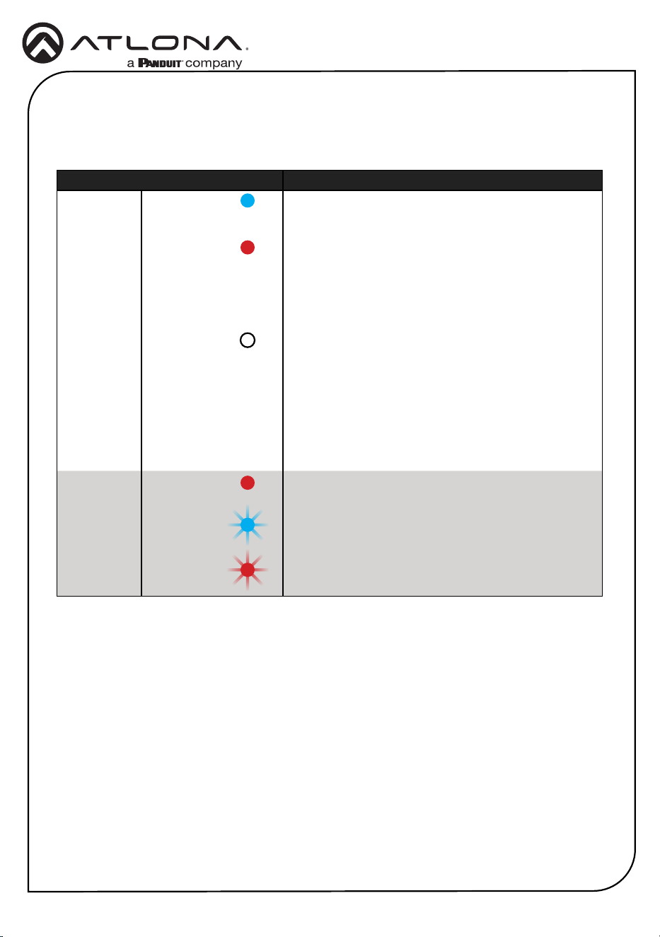
Front Panel LED Indicators
The LED indicators on both the front and rear of the unit provide basic information on the current
status of the unit.
LED State Description
PWR Solid blue Matrix is powered and in normal operating mode.
Solid red The matrix is in standby mode.
Note that when the AT-PRO5-MX810 is placed in
standby mode, the PWR LED indicator will be red.
Off Matrix is not powered.
• Check the power supply and make sure it is
securely fastened to the captive screw connector
on the rear of the unit.
• Make sure that the power supply is connected to
an available electrical outlet and that the outlet
is “live” (some outlets are controlled by a wall
switch).
STATUS Solid red The matrix is booting or is in the process of rebooting.
Blinking blue The matrix is in the process of resetting to factory
defaults.
Blinking red The matrix is updating the rmware.
6
Installation Guide
AT-PRO5-MX810
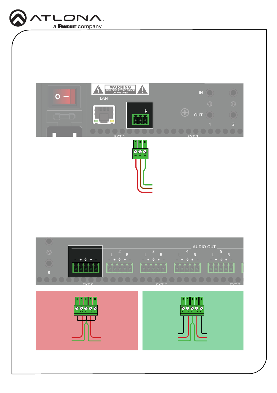
RS-232
AUDIO OUT
Connect the RS-232 cable between the control system and the RS-232 port on the
AT-PRO5-MX810. Use the included 3-pin captive screw connector to wire the RS-232 cable as
shown.
Each AUDIO OUT port can be wired for either unbalanced or balanced output. For unbalanced
audio connections, both negative terminals should be connected to ground. Wire the included
5-pin captive screw connectors as shown.
AT-PRO5-MX810
PWR STATUS
RESET
87654321
1
OUT
IN
RS-232
LAN
RX TX
2
3 4
IR
5 6 7 8
L R
OUTPUTINPUT
10987654321
EXT 6EXT 5EXT 4EXT 3EXT 2EXT 1
AC100-240V 50/60Hz
EXT 7
AUDIO OUT
EXT 8
L R L R L R L R L R L R L R
AT-PRO5-MX810
PWR STATUS
RESET
87654321
1
OUT
IN
RS-232
LAN
RX TX
2 3 4
IR
5 6 7 8
L R
OUTPUTINPUT
10987654321
EXT 6EXT 5EXT 4EXT 3EXT 2EXT 1
AC100-240V 50/60Hz
EXT 7
AUDIO OUT
EXT 8
L R L R L R L R L R L R L R
RX
To control system
TX
GND
}
Unbalanced Audio Balanced Audio
Right Channel
Left Channel
}
}
+
GND
Right Channel
Left Channel
}
}
++
--
GND
AT-PRO5-MX810
PWR STATUS
RESET
876
54321
1
OUT
IN
RS-232
LAN
RX TX
2 3 4
IR
5 6 7
8
L R
OUTPUTINPUT
10987654321
EXT 6EXT 5EXT 4EXT 3EXT 2EXT 1
AC100-240V 50/60Hz
EXT 7
AUDIO OUT
EXT 8
L R L R L R L R
L R L R L R
AT-PRO5-MX810
PWR STATUS
RESET
8765432
1
1
OUT
IN
RS-232
LAN
RX TX
2 3 4
IR
5 6 7 8
L R
OUTPUTINPUT
10987654321
EXT 6EXT 5EXT 4EXT 3EXT 2EXT 1
AC100-240V 50/60Hz
EXT 7
AUDIO OUT
EXT 8
L R
L R L R L R L R L R L R
GND
+
GND
7
Installation Guide
AT-PRO5-MX810
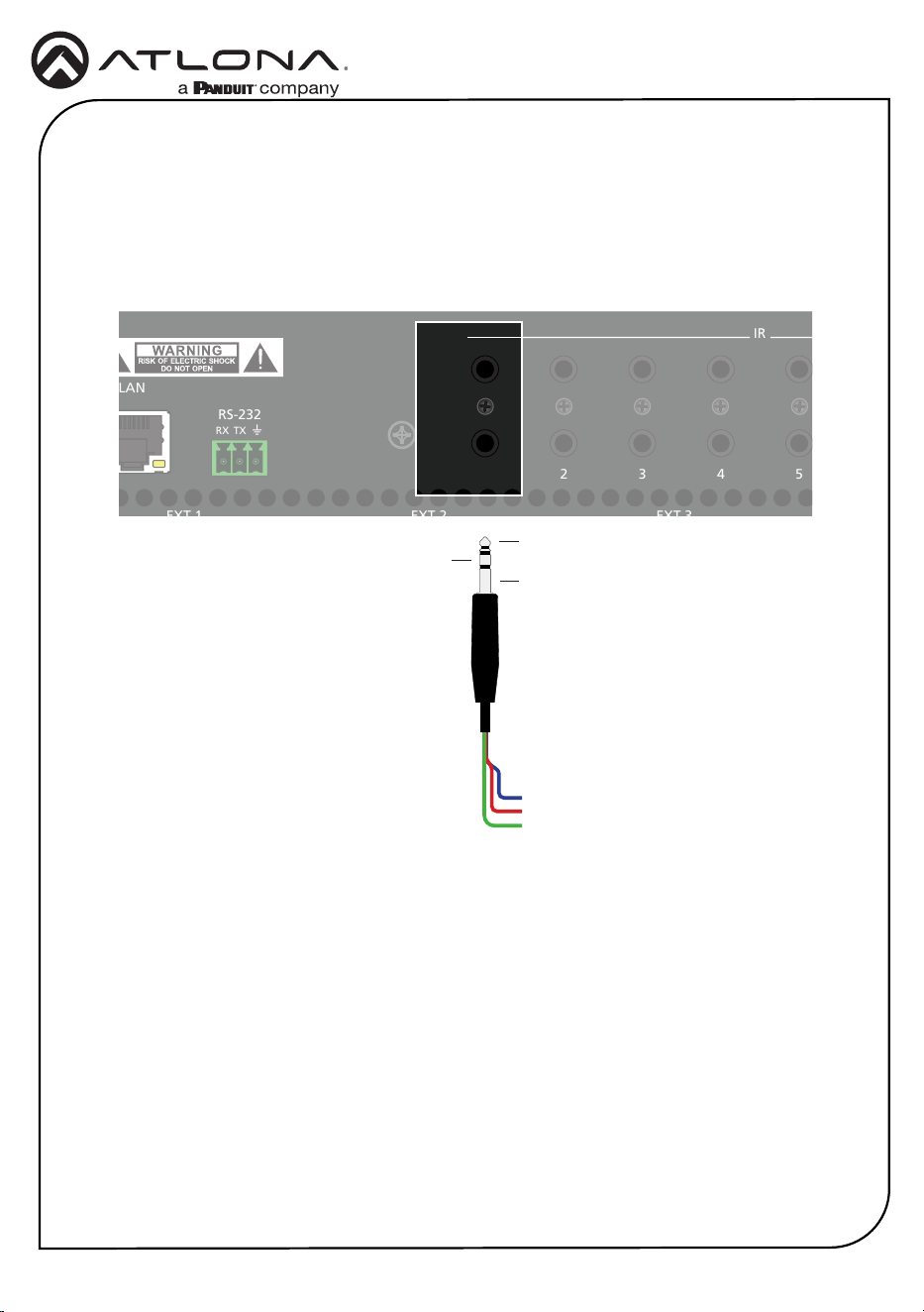
IR IN / IR OUT
Connect the IR emitter or receiver wires to the appropriate contacts on the 3.5mm plug
according to the device’s specication. Note that wire colors within a 3.5 mm cable will vary
depending upon the manufacturer. A multimeter can be used to verify each wire’s function by
checking the contacts on the 3.5 mm jack.
Controlling Headend Devices
Connect an IR emitter to the desired OUT port on the AT-PRO5-MX810. Make sure the source
device is within range of the IR emitter. Refer to the user manual for more information.
Controlling a Display
Connect the IR output of the control system to the desired IN port on the AT-PRO5-MX810.
Refer to the user manual for more information.
AT-PRO5-MX810
PWR STATUS
RESET
87654321
1
OUT
IN
RS-232
LAN
RX TX
2 3 4
IR
5
6 7 8
L R
OUTPUTINPUT
10987654321
EXT 6EXT 5EXT 4EXT 3EXT 2EXT 1
AC100-240V 50/60Hz
EXT 7
AUDIO OUT
EXT 8
L R L R L R L R L R L R L R
AT-PRO5-MX810
PWR STATUS
RESET
87654321
1
OUT
IN
RS-232
LAN
RX TX
2 3 4
IR
5 6 7 8
L R
OUTPUTINPUT
10987654321
EXT 6EXT 5EXT 4EXT 3EXT 2EXT 1
AC100-240V 50/60Hz
EXT 7
AUDIO OUT
EXT 8
L R L R L R L R L R L R L R
Tip
Ring
Sleeve
GND (Sleeve)
SIGNAL (Tip)
POWER (Ring)

8
Installation Guide
AT-PRO5-MX810
Accessing the built-in Web Server
The AT-PRO5-MX810 includes a built-in web server, which allows easy management and control
of all features. Before using the web server, a password must be created.
The AT-PRO5-MX810 is set to DHCP by default and will receive an IP address from the network’s
DHCP pool if a DHCP server is available. If no DHCP server is detected, the AT-PRO5-MX810 will
automatically assign itself an APIPA address in the range 169.254.0.1 to 169.254.255.254,
with a subnet mask of 255.255.0.0.
1. Make sure that an Ethernet cable is connected between one of the LAN ports on the AT-
PRO5-MX810 and the network.
2. Launch a web browser and enter the IP address of the unit. By default, the AT-PRO5-
MX810 is set to DHCP mode and will be assigned an IP address, if a DHCP server is
present on the network.
3. The Login page will be displayed.
4. Enter Atlona in the Password eld.
5. Click Login.
6. The Change Password screen will be displayed.
7. Enter the desired password in the Password eld.
8. Click Apply.

9
Installation Guide
AT-PRO5-MX810
Compatible Transceivers
Manufacturer Product
Atlona AT-SFP-PLUS-10GE-SR
FS FS SFP+ 10GB 859nm LC
Ubiquiti UACC-OM-MM-10G-D-2
Proline EW3D0000710-PRO
StarTech 455883B21ST

10
Installation Guide
AT-PRO5-MX810
Notes

11
Installation Guide
AT-PRO5-MX810
Notes

12
Installation Guide
AT-PRO5-MX810
Notes

13
Installation Guide
AT-PRO5-MX810
Notes

14
Installation Guide
AT-PRO5-MX810
Notes

15
Installation Guide
AT-PRO5-MX810
Notes

16
Installation Guide
AT-PRO5-MX810
25375-R1
®
The terms HDMI, HDMI High-Denition Multimedia Interface, HDMI trade dress and the HDMI Logos are
trademarks or registered trademarks of HDMI Licensing Administrator, Inc.
© 2025 Atlona Inc. All rights reserved. “Atlona” and the Atlona logo are registered trademarks of Atlona Inc. All other brand names and trademarks or registered
trademarks are the property of their respective owners. Pricing, specications and availability subject to change without notice. Actual products, product images, and
online product images may vary from images shown here.
English Declaration of Conformity
The English version can be found under the resources tab at:
https://atlona.com/product/at-pro5-mx810/.
Warranty
Chinese Declaration of Conformity 中国RoHS合格声明
To view the product warranty, use the following link or QR code:
https://atlona.com/warranty/.
由SKU列出於:
https://atlona.com/about-us/china-rohs/.
US International
atlona.com • 408.962.0515 • 41.43.508.4321