1
Installation Guide
AT-HDR-SW-52ED
4K/HDR
5x2 HDMI Matrix Switcher with Mirrored Outputs
AT-HDR-SW-52ED
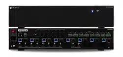
The Atlona AT-HDR-SW-52ED is a 5×2 HDMI matrix switcher for high dynamic range (HDR)
formats. Part of the comprehensive family of Atlona 4K HDR integration products, it features
ve HDMI inputs and matrixed or mirrored HDMI and HDBaseT outputs. The HDBaseT output
transmits video, embedded audio, and Ethernet over distances up to 330 feet (100 meters) to
the AT-HDR-EX-100CEA-RX receiver (available separately). The HDR-SW-52ED is HDCP 2.2
compliant and supports 4K/UHD video @ 60 Hz with 4:4:4 chroma sampling, as well as HDMI
data rates up to 18 Gbps. It is ideal for the latest as well as emerging 4K/UHD and HDR sources
and displays, and includes EDID management features, automatic input switching, and automatic
display control. Additionally, 4K downscaling to 1080p @ 60, 30, or 24 Hz is available for the
outputs when connected to an HD display. The HDR-SW-52ED can de-embed audio from an
HDMI input, or return audio from the HDR-EX-100CEA-RX receiver, to S/PDIF or balanced analog
audio outputs. This HDMI switcher can be controlled via Ethernet, RS-232, and IR.
IMPORTANT: Visit https://www.atlona.com/product/at-hdr-sw-52ed for the
latest rmware updates and User Manual.
1 x AT-HDR-SW-52ED
1 x Captive screw connector, 2-pin
1 x Captive screw connector, 3-pin
2 x Captive screw connector, 5-pin
1 x Long rack ear
1 x Short rack ear
2 x Mounting plates
4 x Mounting screws
4 x Rack screws
4 x Feet w/rubber grips
1 x 48 V / 0.83 A DC power supply
Package Contents

2
Installation Guide
AT-HDR-SW-52ED
HDMI 1
HDMI 2
HDMI 3
HDMI 4
HDMI 5
VOLUME
AT-HDR-SW-52ED
POWER INPUT
S/PDIF OUT
LANFW DC 48V
+
-
1 2 3 4 5
HDMI IN HDMI OUT
L R
++
RX TX
RS-232
OUT
IR
IN
S SP
HDBaseT OUT
AUDIO
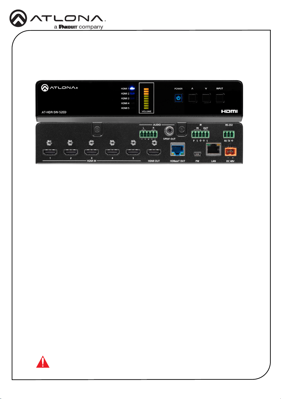
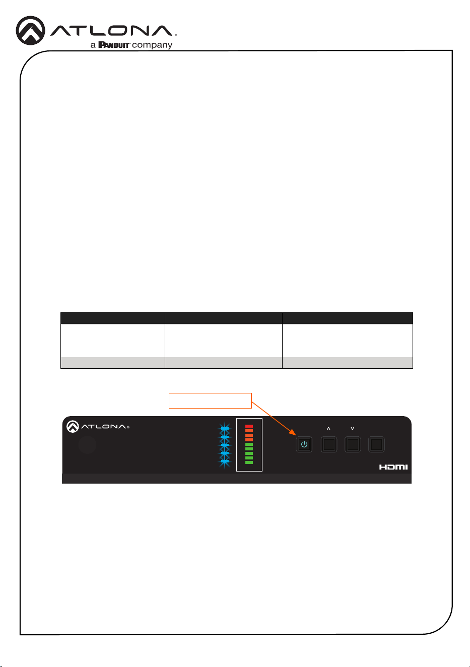
Front Panel Descriptions
1 3 42 5
1 HDMI 1 - HDMI 5
These LED indicators display which input
is routed to the HDMI OUT ports. A solid
blue indicator represents the active input
being used
2 VOLUME
Displays the output audio level.
3 POWER
Press this button to toggle between “on”
and “standby” power states. When in
“standby”, A/V is muted. When “on”, A/V
muting will be disabled.
4 Cursor Buttons
Press and release these buttons to
increase or decrease the audio output
volume on the L/R port.
5 INPUT
Press and release this button to cycle
through each of the HDMI inputs.
3
Installation Guide
AT-HDR-SW-52ED
HDMI 1
HDMI 2
HDMI 3
HDMI 4
HDMI 5
VOLUME
AT-HDR-SW-52ED
POWER INPUT
S/PDIF OUT
LANFW DC 48V
+
-
1 2 3 4 5
HDMI IN HDMI OUT
L R
++
RX TX
RS-232
OUT
IR
IN
S SP
HDBaseT OUT
AUDIO
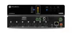
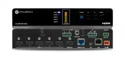
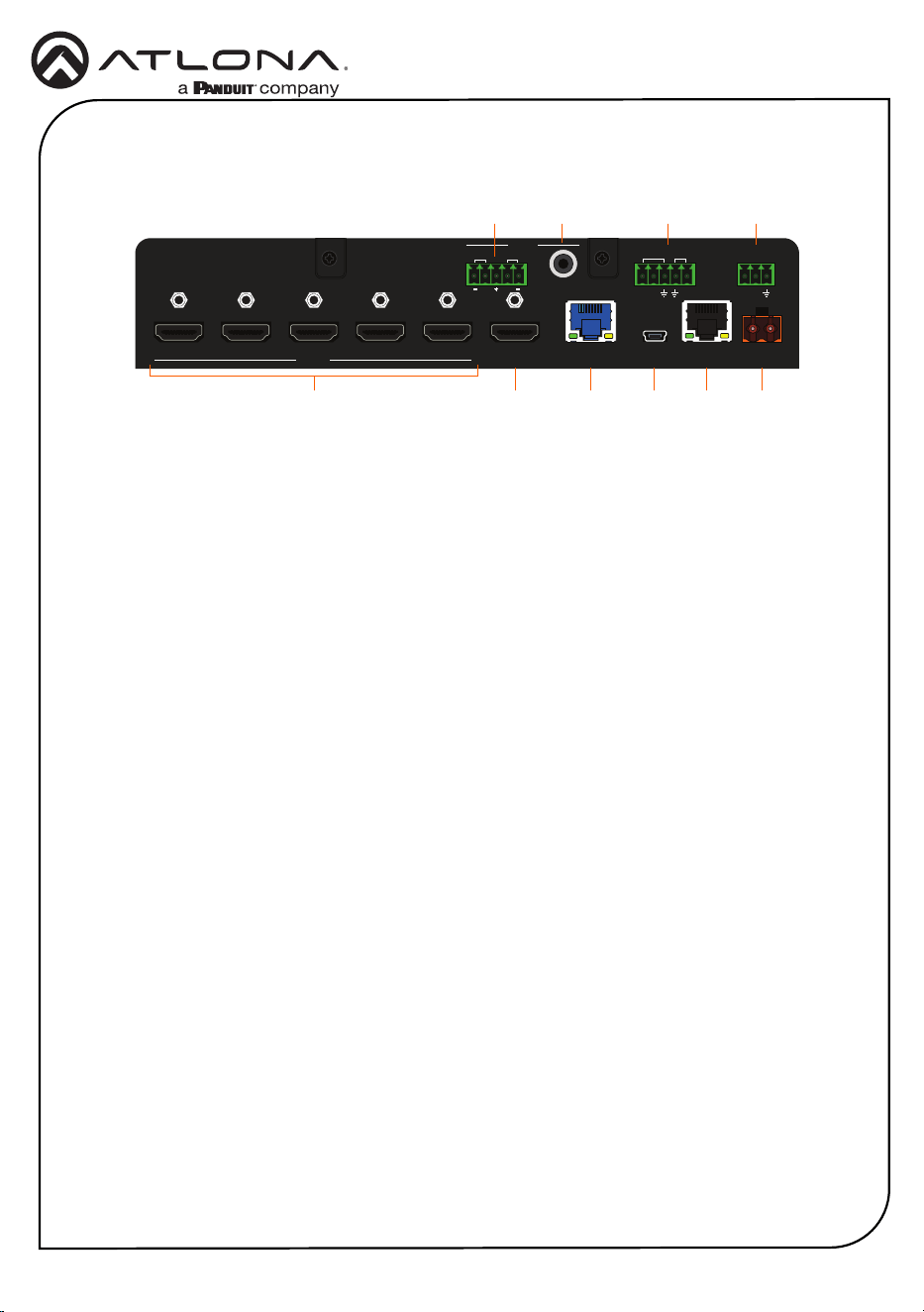
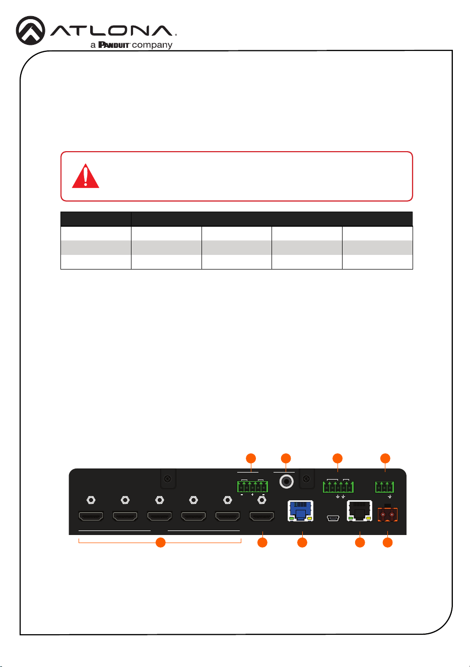
Rear Panel Descriptions
1 63 5 8 10
2 4 97
1 HDMI IN
Connect an HDMI cable from each of
these ports to an HDMI source.
2 L/R
Connect an analog audio output device to
this port using the included captive screw
block. Refer to Audio (page 5) for
information on wiring.
3 HDMI OUT
Connect an HDMI cable from this port to
an HDMI display.
4 S/PDIF OUT
Connect an RCA-type cable from this port
to the S/PDIF audio input port on an A/V
receiver or other audio output device.
5 HDBaseT OUT
Connect a category cable from this port
to a the HDBaseT IN port of a compatible
receiver unit.
6 FW
Connect a USB-to-mini USB cable to
this port from a computer for rmware
updates.
IR IN/OUT
Connect an IR emitter to the OUT (S,
GND) pins to control a display using IR.
Connect a control system to the IN (P, S,
GND) pins. A 5-pin captive screw block
is included. Refer to IR (page 6) for
information on wiring.
7 LAN
Connect an Ethernet cable from this port
to the Local Area Network (LAN). The
AT-HDR-SW-52ED includes a built-in web
server, which can be used to manage and
congure the product.
8 RS-232
Connect the included captive screw block
to an RS-232 controller to control the AT-
HDR-SW-52ED. Refer to RS-232 (page
4) for more information on wiring.
9 DC 48V
Connect the included 48 V DC power
supply from this power receptacle to an
available AC electrical outlet. Refer to
Power (page 4) for more information
on wiring.
4
Installation Guide
AT-HDR-SW-52ED
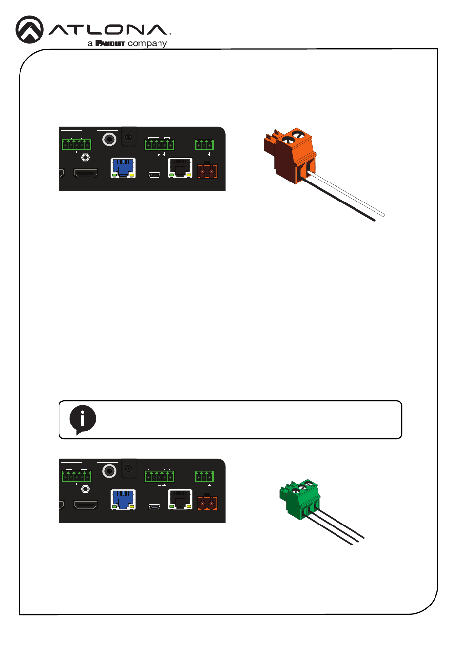
Power
RS-232
POS
White
Black
NEG
Connect the included 2-pin captive screw connector to the DC 48V power receptacle on the rear
of the unit. The captive screw comes pre-wired as shown.
The AT-HDR-SW-52ED provides an RS-232 port which can be used to directly control the AT-
HDR-SW-52ED using a control system.
1. Use wire strippers to remove a portion of the cable jacket.
2. Remove at least 3/16” (5 mm) of insulation from each of the wires.
3. Insert the wires into correct terminal using the included 5-pin captive screw connector.
4. Attach the 3-pin connector block to the RS-232 port on the AT-HDR-SW-52ED.
Control System
AT-HDR-SW-52ED
GND
GND
RxD
TxD
TxD
RxD
NOTE: Typical DB9 connectors use pin 2 for TX, pin 3 for RX, and pin 5
for ground. On some devices functions of pins 2 and 3 are reversed.
HDMI 1
HDMI 2
HDMI 3
HDMI 4
HDMI 5
VOLUME
AT-HDR-SW-52ED
POWER INPUT
S/PDIF OUT
LANFW DC 48V
+
-
1 2 3 4 5
HDMI IN
HDMI OUT
L R
++
RX TX
RS-232
OUT
IR
IN
S SP
HDBaseT OUT
AUDIO
HDMI 1
HDMI 2
HDMI 3
HDMI 4
HDMI 5
VOLUME
AT-HDR-SW-52ED
POWER INPUT
S/PDIF OUT
LANFW DC 48V
+
-
1 2 3 4 5
HDMI IN
HDMI OUT
L R
++
RX TX
RS-232
OUT
IR
IN
S SP
HDBaseT OUT
AUDIO
5
Installation Guide
AT-HDR-SW-52ED
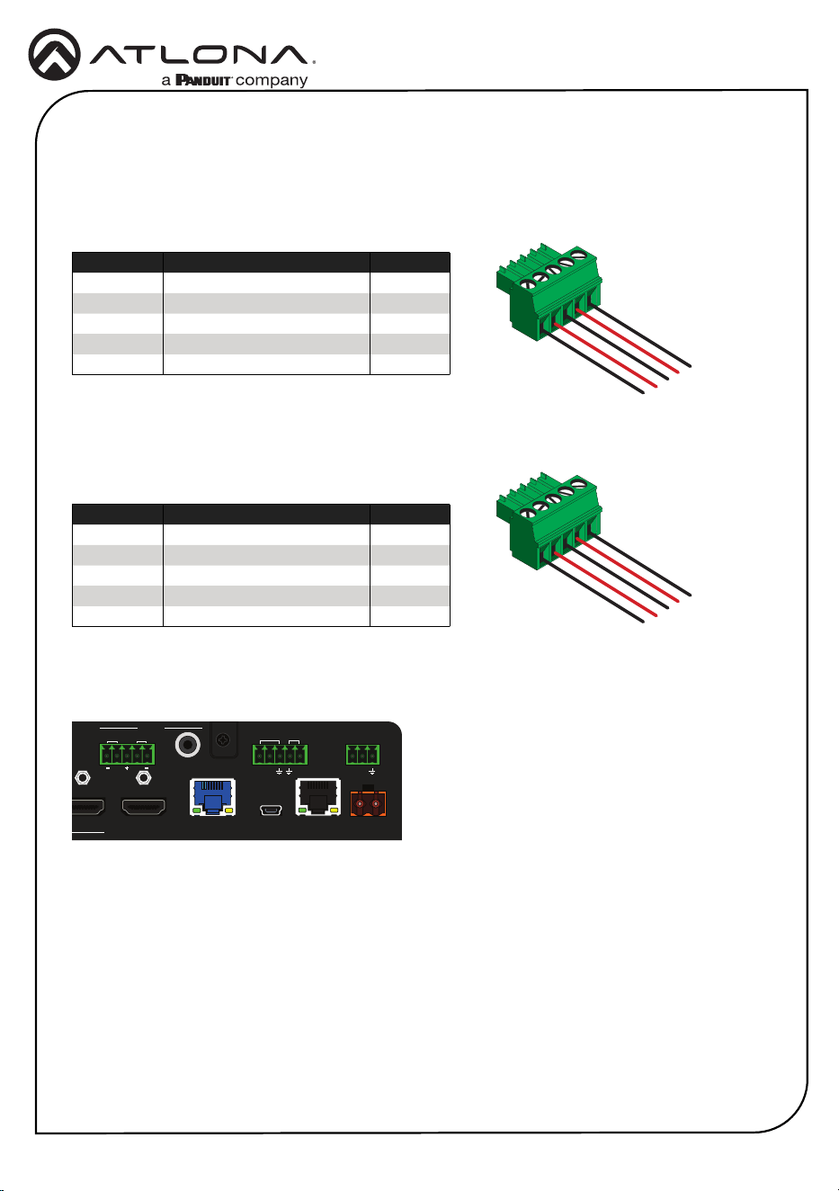
Audio
The included 5-pin captive screw block can be wired to support balanced audio using XLR
connectors, or unbalanced audio using RCA connectors.
*The GND signal, from the 5-pin captive screw connector on
the AT-HDR-SW-52ED, should be tied to pin 1 on both XLR
connectors.
*The GND signal, from the captive screw connector on the AT-
HDR-SW-52ED, should be tied to L- and R- on the captive screw
connector.
GND
+
+
GND
1
2
2
3
3
GND
Balanced Audio (XLR)
Unbalanced Audio (RCA)
Channel Signal (AT-HDR-SW-52ED) Pin (RCA)
R to GND* --
R + +
-- GND GND
L + +
L to GND* --
Channel Signal (AT-HDR-SW-52ED) Pin (XLR)
R - 3
R + 2
-- GND* 1
L + 2
L - 3
HDMI 1
HDMI 2
HDMI 3
HDMI 4
HDMI 5
VOLUME
AT-HDR-SW-52ED
POWER INPUT
S/PDIF OUT
LANFW DC 48V
+
-
1 2 3 4
5
HDMI IN
HDMI OUT
L R
++
RX TX
RS-232
OUT
IR
IN
S SP
HDBaseT OUT
AUDIO
6
Installation Guide
AT-HDR-SW-52ED
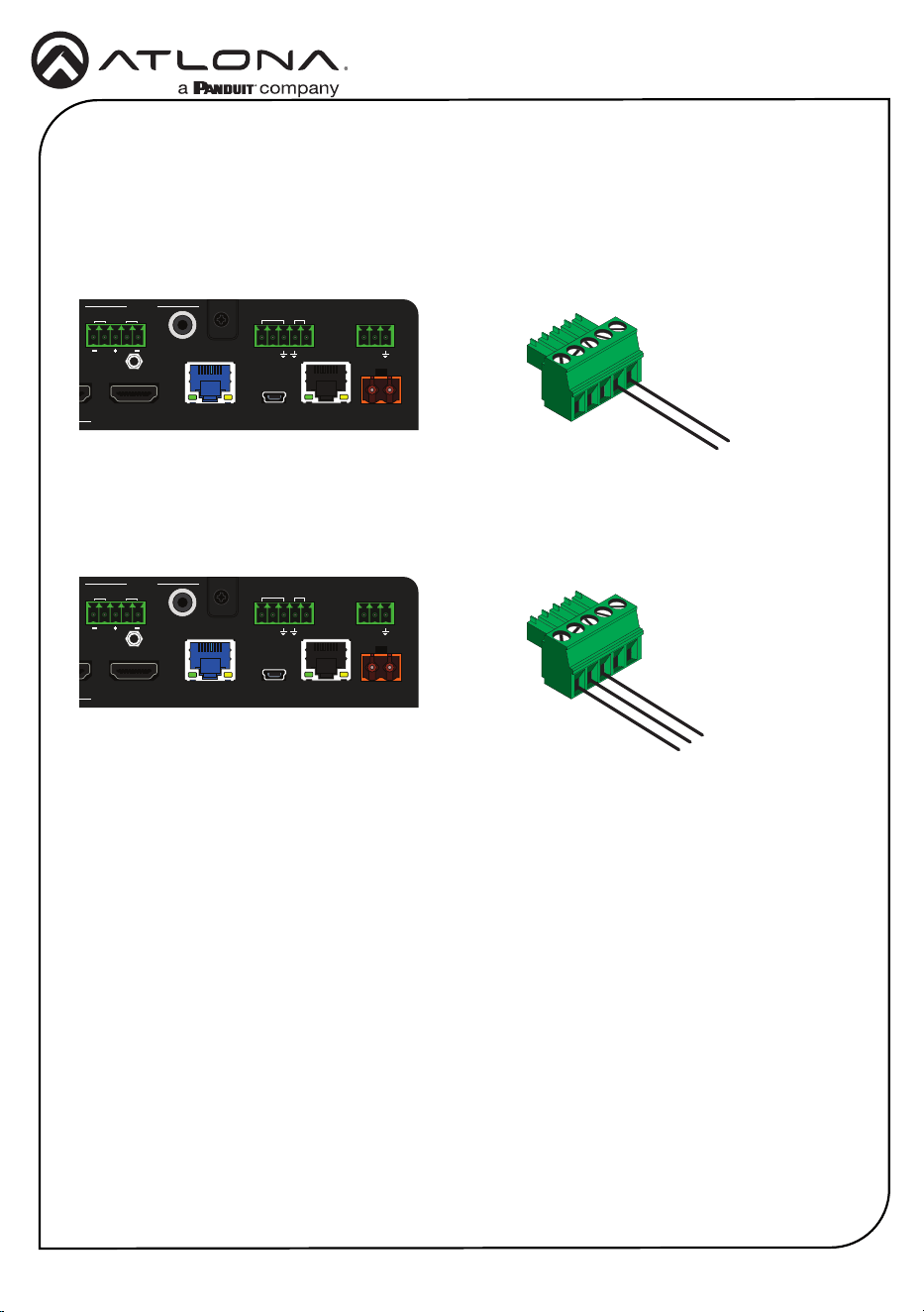
IR
The AT-HDR-SW-52ED provides an IR port which can be used to control a display using an IR
emitter or directly control the AT-HDR-SW-52ED using a control system.
IR Emitter
Control System
AT-HDR-SW-52ED
AT-HDR-SW-52ED
S
S
GND
S
S
GND
GND
P
GND
P
HDMI 1
HDMI 2
HDMI 3
HDMI 4
HDMI 5
VOLUME
AT-HDR-SW-52ED
POWER INPUT
S/PDIF OUT
LANFW DC 48V
+
-
1 2 3 4 5
HDMI IN
HDMI OUT
L R
++
RX TX
RS-232
OUT
IR
IN
S SP
HDBaseT OUT
AUDIO
HDMI 1
HDMI 2
HDMI 3
HDMI 4
HDMI 5
VOLUME
AT-HDR-SW-52ED
POWER INPUT
S/PDIF OUT
LANFW DC 48V
+
-
1 2 3 4 5
HDMI IN
HDMI OUT
L R
++
RX TX
RS-232
OUT
IR
IN
S SP
HDBaseT OUT
AUDIO
Display Control
Controlling the AT-HDR-SW-52ED
7
Installation Guide
AT-HDR-SW-52ED
HDMI 1
HDMI 2
HDMI 3
HDMI 4
HDMI 5
VOLUME
AT-HDR-SW-52ED
POWER INPUT
S/PDIF OUT
LANFW DC 48V
+
-
1 2 3 4 5
HDMI IN HDMI OUT
L R
++
RX TX
RS-232
OUT
IR
IN
S SP
HDBaseT OUT
AUDIO
Installation
1. Connect a source device to each of the HDMI IN (1 - 5) ports.
2. Connect a display device to the HDMI OUT port.
3. Connect a category cable from the HDBaseT OUT port to a the HDBaseT IN port of a
compatible receiver unit, such as the AT-HDR-EX-100CEA-RX.
1 2 3
8
4 9
5 6 7
IMPORTANT: Stranded or patch cable is not recommended due to
performance issues. Shielded cables are strongly recommended to
minimize signal noise and interference.
4. Connect an Ethernet cable from the LAN port to the Local Area Network (LAN). This step
will be required in order to access the built-in web server.
5. Connect the included 5-pin captive screw connector to the 5-pin L/R port. Refer to Audio
(page 5) for more information.
6. Connect an RCA-type cable from the S/PDIF OUT port to an audio output device.
7. Connect the included 5-pin captive screw connector to the 5-pin IR port to use IR control.
Refer to IR (page 6) for more information.
8. Connect an RS-232 cable from the control system to the RS-232 port. Refer to RS-232
(page 4) for more information.
9. Connect the included power supply to the DC 48V connector and connect the power cord
to an available electrical outlet.
Cable 4K/UHD - Feet / Meters 1080p - Feet / Meters
HDMI IN/OUT 15 5 30 10
CAT5e 295 90 330 100
CAT6/6a/7 330 100 330 100
8
Installation Guide
AT-HDR-SW-52ED
S/PDIF OUT
LANFW DC 48V
+
-
1 2 3 4 5
HDMI IN HDMI OUT
L R
++
RX TX
RS-232
OUT
IR
IN
S SP
HDBaseT OUT
AUDIO
HDMI 1
HDMI 2
HDMI 3
HDMI 4
HDMI 5
VOLUME
AT-HDR-SW-52ED
POWER INPUT
The AT-HDR-SW-52ED is shipped with DHCP enabled. Once connected to a network, the DHCP
server (if available), will automatically assign an IP address to the unit. If the AT-HDR-SW-52ED
is unable to detect a DHCP server within 15 seconds, then the unit will use a self-assigned IP
address within the range of 169.254.xxx.xxx/16. If this occurs, refer to the AT-HDR-SW-
52ED User Manual for more information.
Use an IP scanner, along with the MAC address on the bottom of the unit, to identify the unit on
the network. If a static IP address is desired, the unit can be switched to static IP mode.
IP Conguration
Switching the IP mode using the Front Panel
1. Make sure the AT-HDR-SW-52ED is powered.
2. Connect an Ethernet cable between the LAN port of the AT-HDR-SW-52ED and the Local
Area Network (LAN).
3. Press and hold the POWER button for approximately 15 seconds. Release the POWER
button once all the front-panel LED indicators begin to ash. The number of ashes will
indicate the currently selected IP mode. Refer to the table, below.
POWER button ashes Description Settings
Two Static IP mode IP address: 192.168.1.254
Netmask: 255.255.0.0
Gateway: 192.168.1.1
Four DHCP mode DHCP server assigned
POWER button

9
Installation Guide
AT-HDR-SW-52ED
Accessing the built-in Web Server
The AT-HDR-SW-52ED includes a built-in web server, which allows easy management and
control of all features. Follow the instructions below to access the web server.
1. Make sure that an Ethernet cable is connected between the LAN port on the AT-HDR-SW-
52ED and the network.
2. Launch a web browser and enter the IP address of the unit.
3. The AT-HDR-SW-52ED Register page will be displayed.
4. Create a username and password.
5. Click the Register button.
6. The Login page will be displayed.
7. Enter the username and password that was created during the registration process.
8. Click the Login button.
9. Refer to User Manual for more information on using the built-in web server.

10
Installation Guide
AT-HDR-SW-52ED
Notes

11
Installation Guide
AT-HDR-SW-52ED
Notes

12
Installation Guide
AT-HDR-SW-52ED
25295-R1
®
The terms HDMI, HDMI High-Denition Multimedia Interface, and the HDMI Logo are trademarks or
registered trademarks of HDMI licensing Administrator, Inc.
© 2023 Atlona Inc. All rights reserved. “Atlona” and the Atlona logo are registered trademarks of Atlona Inc. All other brand names and trademarks or registered
trademarks are the property of their respective owners. Pricing, specications and availability subject to change without notice. Actual products, product images, and
online product images may vary from images shown here.
English Declaration of Conformity
The English version can be found under the resources tab at:
https://atlona.com/product/at-hdr-sw-52ed/.
Warranty
Chinese Declaration of Conformity 中国RoHS合格声明
To view the product warranty, use the following link or QR code:
https://atlona.com/warranty/.
由SKU列出於:
https://atlona.com/about-us/china-rohs/.
US International
atlona.com • 408.962.0515 • 41.43.508.4321