1
Installation Guide
AT-HDR-MX1616
4K HDR HDBaseT Matrix Switcher
AT-HDR-MX1616
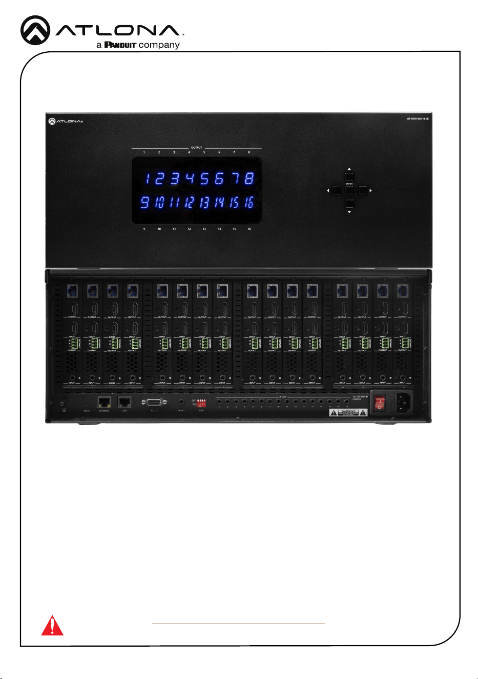
The Atlona AT-HDR-MX1616 is a 16x16 HDMI
®
to HDBaseT™ matrix switcher for high dynamic
range (HDR) formats. It is HDCP 2.2 compliant, supports 4K/UHD video @ 60 Hz with 4:4:4 chro-
ma sampling, and data rates up to 18 Gbps.
IMPORTANT: Visit https://atlona.com/product/at-hdr-mx1616 for the latest rmware
updates and Installation Guide.
1 x AT-HDR-MX1616
16 x Captive screw connector, 3-pin
1 x IEC Cable
1 x Pair of mounting ears w/screws
4 x Feet w/screw
1 x Installation Guide
Package Contents
2
Installation Guide
AT-HDR-MX1616
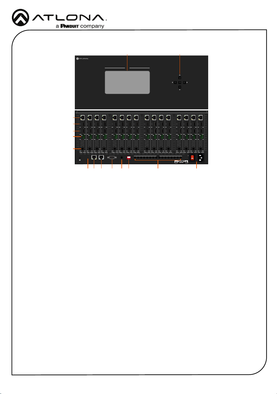
Panel Descriptions
AT-HDR-MX1616
21 3 5 6 7 84
109 11 13 14 15 1612
OUTPUT
ENTER
1 2 3
4
ON
ANALOG
L R
IR
L R
L R
L R
L R
L R
L R
L R
L R
L R
L R
L R
L R
L R
L R
L R
INPUT INPUT INPUT INPUT INPUT INPUT INPUT INPUT INPUT INPUT INPUT INPUT INPUT INPUT INPUT INPUT
INPUT INPUT INPUT INPUT INPUT INPUT INPUT INPUT INPUT INPUT INPUT INPUT INPUT INPUT INPUT INPUT
OUTPUT OUTPUT OUTPUT OUTPUT OUTPUT OUTPUT OUTPUT OUTPUT OUTPUT OUTPUT OUTPUT OUTPUT OUTPUT OUTPUT OUTPUT OUTPUT
OUTPUT OUTPUT OUTPUT OUTPUT OUTPUT OUTPUT OUTPUT OUTPUT OUTPUT OUTPUT OUTPUT OUTPUT OUTPUT OUTPUT OUTPUT OUTPUT
ON
OFF
LAN RS-232 IR EXT EDID
ETHERNETRESET
AC 100-240V
50/60Hz
1 2 3 4 5 6 7 8 9 10 11 12 13 14 15 16
IR OUT
1 2 3 4
5 6
7
8 9
10 11 12 13 14 15 16
ANALOGIR
ANALOG
ANALOG
IR
ANALOGIR
ANALOG
IR
ANALOG
IR
ANALOG
IR
ANALOG
IR
ANALOG
IR
ANALOG
IR
ANALOG
IR
ANALOG
IR
ANALOG
IR
ANALOG
IR
ANALOG
IR
1 Front Panel Display
Front panel display will show the on-
screen menu for routing.
2 Selection Buttons
Use to route inputs and outputs via the
OSD.
3 HDBaseT OUT
Connect PoE compatible receivers to this
port.
4 HDMI OUT
Connect an HDMI display to this port. This
port is mirrored and will display the same
content as the HDBaseT OUT port.
5. INPUT
Connect an HDMI source to this port.
6 AUDIO OUT
Connect the included 3-pin captive screw
connector between this port and an
amplier.
7 IR
Connect an IR receiver or control system
to this port for remote device control.
8 Reset
Press and hold for 5 seconds to reset the
IP mode to DHCP or press and hold for
15 seconds to reset the unit to factory
settings.
9 ETHERNET
Connect an RJ45 cable to this port to
a network switch or source for Ethernet
pass through. When connected to a
network switch, Ethernet will pass to
compatible remote HDBaseT receivers.
10 LAN
Connect an RJ45 cable to this port for
TCP/IP and Web Server control of the
matrix.
11 RS-232
Connect to an RS-232 device or control
system.
12 IR EXT
Connect to an IR Receiver for use with an
IR remote.
13 EDID
Use to manually set the EDID mode for
the unit.
14 IR OUT
Connect IR transmitters to these ports for
local device control.
15 AC 100-240V 50/60Hz
Connect the included IEC cable from this
port to a wall to power the unit.
8
149 10 11 12 13
3
4
5
6
7
15
21
3
Installation Guide
AT-HDR-MX1616
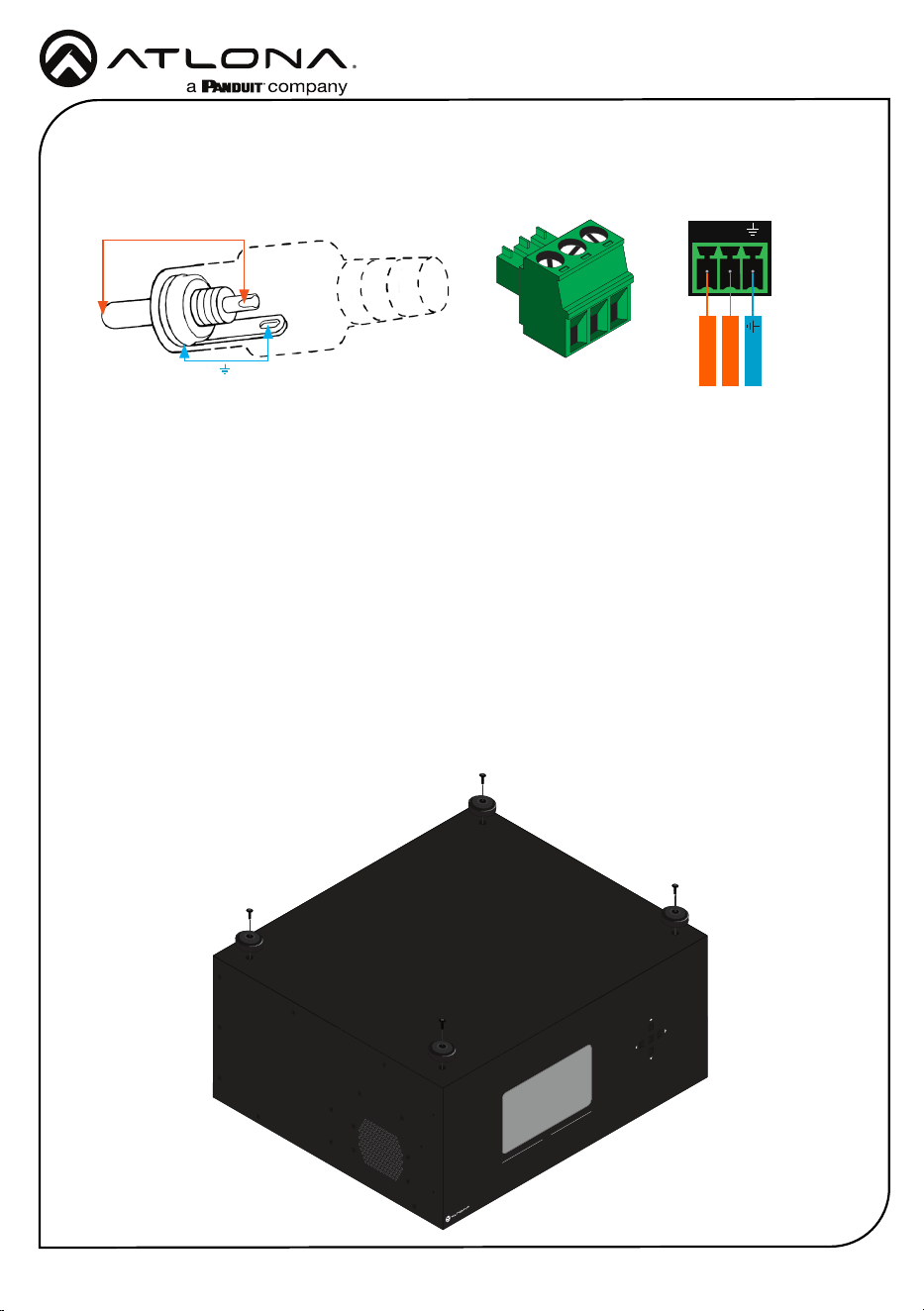
Audio
Mounting Instructions
Connect to an audio DSP, amplier, or other audio distribution or player devices. Only
unbalanced connections may be used.
L
R
L - Signal
Ground
R - Signal
Unbalanced
The AT-HDR-MX1616 can be placed freestanding on top of a desk, a table, or in a cabinet. To
prevent damage to the surfaces or unnecessary movement of the matrix, four feet have been
included.
Surface mounting
The AT-HDR-MX1616 can be placed freestanding on top of a desk, a table, or in a cabinet. To
prevent damage to the surfaces or unnecessary movement of the matrix, four feet have been
included.
1. Turn the unit upside down.
2. Install each foot using the included feet screws, the rubber grips of the feet should be facing
up during installation.
3. Turn the unit right-side up and place it in the desired location.
AT-HDR-MX1616
21 3 5 6 7 84
109 11 13 14 15 1612
OUTPUT
ENTER
1 2 3
4
ON
ANALOG
L R
IR
L R
L R
L R
L R
L R
L R
L R
L R
L R
L R
L R
L R
L R
L R
L R
INPUT
INPUT
INPUT
INPUT
INPUT
INPUT
INPUT
INPUT
INPUT
INPUT
INPUT
INPUT
INPUT
INPUT
INPUT
INPUT
INPUT
INPUT
INPUT
INPUT
INPUT
INPUT
INPUT
INPUT
INPUT
INPUT
INPUT
INPUT
INPUT
INPUT
INPUT
INPUT
OUTPUT
OUTPUT
OUTPUT
OUTPUT
OUTPUT
OUTPUT
OUTPUT
OUTPUT
OUTPUT
OUTPUT
OUTPUT
OUTPUT
OUTPUT
OUTPUT
OUTPUT
OUTPUT
OUTPUT
OUTPUT
OUTPUT
OUTPUT
OUTPUT
OUTPUT
OUTPUT
OUTPUT
OUTPUT
OUTPUT
OUTPUT
OUTPUT
OUTPUT
OUTPUT
OUTPUT
OUTPUT
ON
OFF
LAN RS-232 IR EXT
EDID
ETHERNET
RESET
AC 100-240V
50/60Hz
1 2 3 4 5 6 7 8 9 10 11 12 13 14 15 16
IR OUT
1
2
3
4
5
6
7
8
9
10
11
12
13
14
15
16
ANALOGIR
ANALOG
ANALOG
IR
ANALOGIR
ANALOG
IR
ANALOG
IR
ANALOG
IR
ANALOG
IR
ANALOG
IR
ANALOG
IR
ANALOG
IR
ANALOG
IR
ANALOG
IR
ANALOG
IR
ANALOG
IR
Tip (+)
RCA
Sleeve ( Ground)
4
Installation Guide
AT-HDR-MX1616
AT-HDR-MX1616
21 3 5 6 7 84
109 11 13 14 15 1612
OUTPUT
ENTER
12
3
4
ON
ANALOG
L R
IR
L R
L R
L R
L R
L R
L R
L R
L R
L R
L R
L R
L R
L R
L R
L R
INPUT
INPUT
INPUT
INPUT
INPUT
INPUT
INPUT
INPUT
INPUT
INPUT
INPUT
INPUT
INPUT
INPUT
INPUT
INPUT
INPUT
INPUT
INPUT
INPUT
INPUT
INPUT
INPUT
INPUT
INPUT
INPUT
INPUT
INPUT
INPUT
INPUT
INPUT
INPUT
OUTPUT
OUTPUT
OUTPUT
OUTPUT
OUTPUT
OUTPUT
OUTPUT
OUTPUT
OUTPUT
OUTPUT
OUTPUT
OUTPUT
OUTPUT
OUTPUT
OUTPUT
OUTPUT
OUTPUT
OUTPUT
OUTPUT
OUTPUT
OUTPUT
OUTPUT
OUTPUT
OUTPUT
OUTPUT
OUTPUT
OUTPUT
OUTPUT
OUTPUT
OUTPUT
OUTPUT
OUTPUT
ON
OFF
LAN RS-232 IR EXT EDID
ETHERNETRESET
AC 100-240V
50/60Hz
1 2 3 4 5 6 7 8 9 10 11 12 13 14 15 16
IR OUT
1
2
3
4
5
6
7
8
9
10
11
12
13
14
15
16
ANALOGIR
ANALOG
ANALOG
IR
ANALOGIR
ANALOG
IR
ANALOG
IR
ANALOG
IR
ANALOG
IR
ANALOG
IR
ANALOG
IR
ANALOG
IR
ANALOG
IR
ANALOG
IR
ANALOG
IR
ANALOG
IR
AT-HDR-MX1616
4K HDR 16x16
Matrix Switcher
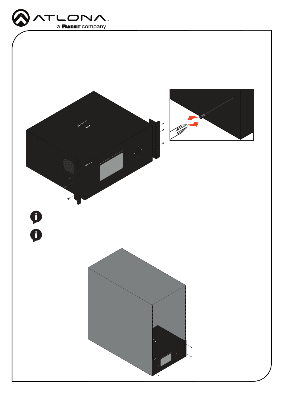
Rack installation
1. *Optional* If the unit still has the feet on it, remove them before installing.
2. Attach the included rack ears to each side of the AT-HDR-MX1616 using the included
mounting screws.
3. Install the HDR-MX1616 into a rack, using four rack screws.
AT-HDR-MX1616
21 3 5 6 7 84
109 11 13 14 15 1612
OUTPUT
ENTER
1 2 3
4
ON
ANALOG
L R
IR
L R
L R
L R
L R
L R
L R
L R
L R
L R
L R
L R
L R
L R
L R
L R
INPUT
INPUT
INPUT
INPUT
INPUT
INPUT
INPUT
INPUT
INPUT
INPUT
INPUT
INPUT
INPUT
INPUT
INPUT
INPUT
INPUT
INPUT
INPUT
INPUT
INPUT
INPUT
INPUT
INPUT
INPUT
INPUT
INPUT
INPUT
INPUT
INPUT
INPUT
INPUT
OUTPUT
OUTPUT
OUTPUT
OUTPUT
OUTPUT
OUTPUT
OUTPUT
OUTPUT
OUTPUT
OUTPUT
OUTPUT
OUTPUT
OUTPUT
OUTPUT
OUTPUT
OUTPUT
OUTPUT
OUTPUT
OUTPUT
OUTPUT
OUTPUT
OUTPUT
OUTPUT
OUTPUT
OUTPUT
OUTPUT
OUTPUT
OUTPUT
OUTPUT
OUTPUT
OUTPUT
OUTPUT
ON
OFF
LAN RS-232 IR EXT EDID
ETHERNETRESET
AC 100-240V
50/60Hz
1 2 3 4 5 6 7 8 9 10 11 12 13 14 15 16
IR OUT
1
2
3
4
5
6
7
8
9
10
11
12
13
14
15
16
ANALOGIR
ANALOG
ANALOG
IR
ANALOGIR
ANALOG
IR
ANALOG
IR
ANALOG
IR
ANALOG
IR
ANALOG
IR
ANALOG
IR
ANALOG
IR
ANALOG
IR
ANALOG
IR
ANALOG
IR
ANALOG
IR
AT-HDR-MX1616
4K HDR 16x16
Matrix Switcher
NOTE: Increase the air ow as needed to maintain the recommended temperature
inside the rack.
NOTE: Do not exceed the maximum weight loads for the rack. Install heavier
equipment in the lower part of the rack for stability.
5
Installation Guide
AT-HDR-MX1616
Connection Instructions
1. Connect up to 16 HDMI sources to the HDMI input ports.
2. Connect up to 16 HDMI displays to the HDMI output ports.
3. Connect an RJ45 cable from a network switch to the LAN port for unit control and Web
Server access.
4. Connect an RJ45 cable to the ETHERNET port for Ethernet data pass through to remote
compatible HDBaseT receivers.
5. Connect up to 16 3-pin captive screw connectors from the analog audio out ports to a DSP,
amplier, or other audio distribution or player devices.
6. Connect up to 16 compatible HDBaseT receivers (e.g. AT-HDR-EX-100CEA-RX) to the
HDBaseT output ports.
7. For control, connect IR receivers to the IR IN or IR Ext ports of the unit and IR transmitters
to the IR OUT ports.
8. Connect a female DB9 RS-232 cable to this port for unit control.
9. Connect the included IEC cable from the AC 100-240V 50/60Hz port to an AC outlet.
NOTE: IR IN 1 through 16 are bound with HDBaseT OUT 1 through 16.
NOTE: IR OUT 1 through 16 are bound with HDMI IN 1 through 16.
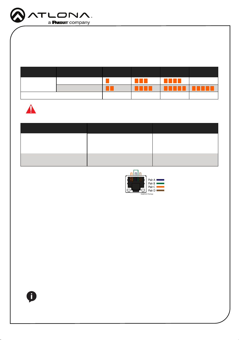
Core Shielding CAT5e CAT6 CAT6a CAT7
Solid UTP (unshielded) N/A
STP (shielded)
Performance Rating (MHz) 350 500 600 800
Resolution/Distance Distance Resolution
CAT 5e/6 100m/330ft 1080p@60Hz 4:4:4 10-bit
70m/230ft 1080p@60Hz 4:4:4 12-bit
4K@60Hz 4:4:4 8-bit
CAT 6a/7 100m/330ft 1080p@60Hz 4:4:4 12-bit
4K@60Hz 4:4:4 8-bit
Cable Recommendation Guidelines
Refer to the tables below for recommended cabling when using Altona products with HDBaseT.
The green bars indicate the signal quality when using each type of cable. Higher-quality signals
are represented by more bars.
IMPORTANT: Stranded or patch cables are not recommended due to performance
issues. Shielded cables are strongly recommended to minimize signal noise and
interference.
Use of a TIA/EIA 568B termination is
recommended for optimal performance.

6
Installation Guide
AT-HDR-MX1616
Notes

7
Installation Guide
AT-HDR-MX1616
Notes
8
Installation Guide
AT-HDR-MX1616
Version 1
English Declaration of Conformity
The English version can be found under the resources tab at:
https://atlona.com/product/at-hdr-mx1616.
© 2025 Atlona Inc. All rights reserved. “Atlona” and the Atlona logo are registered trademarks of Atlona Inc. All other brand names and trademarks or registered
trademarks are the property of their respective owners. Pricing, specications and availability subject to change without notice. Actual products, product images,
and online product images may vary from images shown here.
US International
atlona.com • 408.962.0515 • 41.43.508.4321
25378-R1
Warranty
Chinese Declaration of Conformity 中国RoHS合格声明
To view the product warranty, use the following link or QR code:
https://atlona.com/warranty/.
由SKU列出於:
https://atlona.com/about-us/china-rohs/.