Installation Guide
1
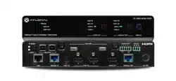
AT-OME-MS42-HDBT
Omega
4x2 Matrix Switcher with HDMI and HDBaseT Inputs
AT-OME-MS42-HDBT
1 x AT-OME-MS42-HDBT
1 x 2 m USB-C cable
1 x Captive screw connector, 5-pin
1 x Captive screw connector, 3-pin
1 x USB-C cable
2 x Mounting plate
4 x Mounting screws
4 x Feet w/rubber grips
1 x 24V DC power supply
1 x IEC power cord
Package Contents
The Atlona AT-OME-MS42-HDBT is a 4×2 matrix switcher with HDMI, USB-C, and HDBaseT
inputs, plus HDMI and HDBaseT outputs. Part of the Omega™ Series of integration products for
modern AV communications and collaboration, the OME-MS42-HDBT is HDCP 2.2 compliant
and features HDBaseT extension for video up to 4K/60 4:2:0, plus embedded audio, control,
Ethernet, and USB over distances up to 330 feet (100 meters). The local HDMI and USB-C
inputs, and HDMI output support 4K HDR and 4K/60 4:4:4 at data rates up to 18 Gbps.
Additionally, 4K downscaling to 1080p @ 60, 30, or 24 Hz is available for the HDMI output when
connected to an HD sink. The integrated USB extension addresses the challenge of connecting
between USB devices at remote locations, and is ideal for software video conferencing and
touch or interactive displays. The OME-MS42-HDBT features switching for up to four host PCs
through USB 2.0 type B and USB-C ports, and remotely over HDBaseT. A built-in USB 2.0 hub
provides connectivity for two peripheral devices such as a camera, microphone, speakerphone,
or keyboard and mouse.
IMPORTANT: Visit https://atlona.com/product/at-ome-ms42-hdbt for the latest rmware
updates and User Manual.
Installation Guide
2
AT-OME-MS42-HDBT
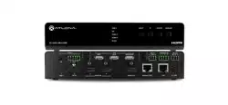
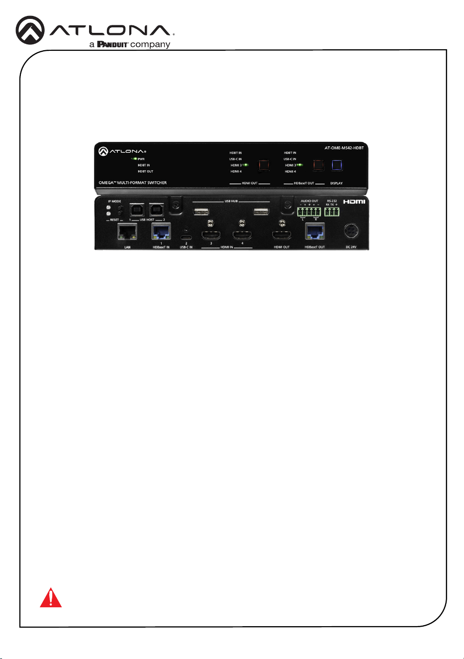
Front Panel Descriptions
1 PWR
The LED indicator glows solid green when
the unit is powered.
HDBT IN
This LED indicator glows solid green when
a compatible HDBaseT transmitter is
connected to the HDBaseT IN port.
HDBT OUT
This LED indicator glows solid green
when a compatible HDBaseT receiver is
connected to the HDBaseT OUT port.
2 HDMI OUT: Input LED Indicators
These LED indicators display which input
is routed to the HDMI OUT port. A solid
green indicator represents the active input
being used.
3 HDMI OUT: Input Selection
Press and release this button to change
the input.
4 HDBaseT OUT: Input LED Indicators
These LED indicators display which input
is routed to the HDBaseT OUT port. A
solid blue indicator represents the active
input being used.
5 HDBaseT OUT: Input Selection
Press and release this button to change
the input.
6 DISPLAY
Press this button to toggle the power state
of the desired display. Refer to the User
Manual for more information.
OMEGA
TM
MULTI-FOMAT SWITCHER
USB-C IN
HDMI 3
HDBT IN
HDMI OUT
HDMI 4
USB-C IN
HDMI 3
HDBT IN
HDMI 4
HDBaseT OUT DISPLAY
PWR
HDBT IN
HDBT OUT
AT-OME-MS42-HDBT
AUDIO OUT
RS-232
L R
RX TX
++
USBUSB
USB HUB
DC 24V
RESET
USB HOST1 2
2
USB-C IN HDMI OUT
4
3
HDMI INLAN
1
HDBaseT OUTHDBaseT IN
IP MODE
1 2 43 5 6
Installation Guide
3
AT-OME-MS42-HDBT
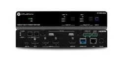
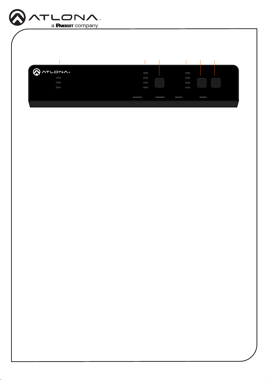
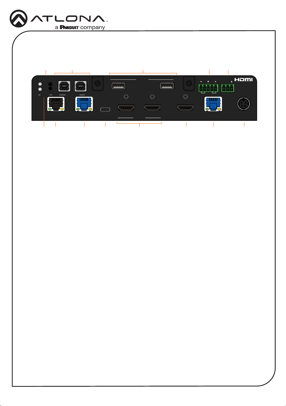
Rear Panel Descriptions
OMEGA
TM
MULTI-FOMAT SWITCHER
USB-C IN
HDMI 3
HDBT IN
HDMI OUT
HDMI 4
USB-C IN
HDMI 3
HDBT IN
HDMI 4
HDBaseT OUT DISPLAY
PWR
HDBT IN
HDBT OUT
AT-OME-MS42-HDBT
AUDIO OUT
RS-232
L R
RX TX
+
+
USBUSB
USB HUB
DC 24V
RESET
USB HOST1 2
2
USB-C IN HDMI OUT
4
3
HDMI INLAN
1
HDBaseT OUTHDBaseT IN
IP MODE
3 5 6 9 11 132
8
41 7 10 12
1 IP MODE
Press and release this button to set the IP
mode or display the current IP address on
the display connected to the HDMI OUT
port.
2 RESET
Press and release this button to reset the
unit to factory-default settings. Refer to
the User Manual for more information.
3 LAN
Connect an Ethernet cable from this port
to the Local Area Network (LAN). The
AT-OME-MS42-HDBT-HDBT includes a
built-in web server, which can be used to
manage and congure the product.
4 USB HOST
Connect a USB cable from each of these
ports to USB host devices.
5 HDBaseT IN
Connect a compatible HDBaseT
transmitter to this port.
6 USB-C IN
Connect a USB-C cable between from
this port to a USB-C source.
7 USB HUB
Connect USB devices to these USB ports.
8 HDMI IN
Connect an HDMI cable from each of
these ports to HDMI sources.
9 HDMI OUT
Connect an HDMI cable from this port to a
display or other sink device.
10 AUDIO OUT
Connect an audio output device to this
port using the included captive screw
block. Refer to the next page for wiring
information.
11 HDBaseT OUT
Connect a category cable from this
port to a compatible receiver unit.
Recommended receiver is the
AT-OME-EX-RX.
12 RS-232
Connect the included 3-pin captive screw
connector block to this port. Refer to the
next page for wiring information.
13 DC 24V
Connect the included 24 V DC power
supply from this power receptacle to an
available AC electrical outlet.
Installation Guide
4
AT-OME-MS42-HDBT
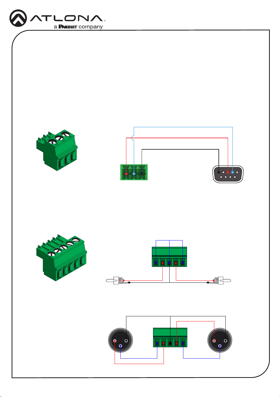
The AT-OME-MS42-HDBT provides an RS-232 port which can be used to control a display
connected to the HDMI output. Atlona recommends controlling the AT-OME-MS42-HDBT using
IP and reserving the RS-232 port for local display control.
1 Use wire strippers to remove a portion of the cable jacket.
2 Remove at least 3/16” (5 mm) of insulation from each of the wires.
3 Insert the wires into correct terminal using the included 3-pin captive screw connector.
4 Attach the 3-pin connector block to the RS-232 port on the AT-OME-MS42-HDBT.
The AT-OME-MS42-HDBT provides two-channel LPCM audio de-embedding of the source
device, using a dedicated AUDIO port. Use the included 5-pin captive-screw terminal block.
Balanced audio connections use two signal wires and a ground to minimize interference in audio
signals.
RS-232
Audio
GND
RX
TX
GND
Side View Side View
+
GND
+
-
2 1
3
2 1
3
GND GND
-
+
Rear View
Rear View
-
+
Unbalanced
Balanced
Installation Guide
5
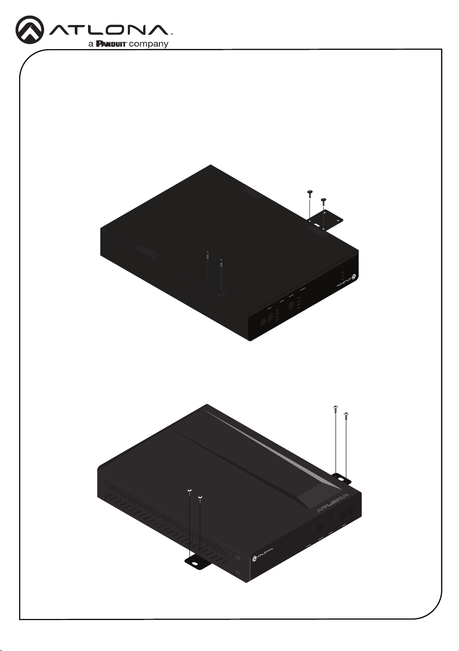
AT-OME-MS42-HDBT
1 Turn the unit upside down on a at surface.
2 Position the included mounting plates over the pre-drilled holes on the bottom of the
enclosure. Use the included mounting screws to attach the mounting plates. When
attaching mounting plates, the countersink bevels on the mounting plates should face
upward.
PWR
VOL LEVEL
AUDIO AMPLIFIER
FWSIGNAL ANALOG IN
NET AUDIODEVICE ID
GAIN
TM
OMEGA
TM
MULTI-FOMAT SWITCHER
USB-C IN
HDMI 3
HDBT IN
HDMI OUT
HDMI 4
USB-C IN
HDMI 3
HDBT IN
HDMI 4
HDBaseT OUT DISPLAY
PWR
HDBT IN
HDBT OUT
AT-OME-MS42-HDBT
3 Mount the unit using the circular holes, on each mounting plate. Mounting screws are not
included.
OMEGA
TM
MULTI-FOMAT SWITCHER
USB-C IN
HDMI 3
HDBT IN
HDMI OUT
HDMI 4
USB-C IN
HDMI 3
HDBT IN
HDMI 4
HDBaseT OUT DISPLAY
PWR
HDBT IN
HDBT OUT
AT-OME-MS42-HDBT
Mounting Instructions
The AT-OME-MS42-HDBT can be mounted under a desk, lectern, or other at surface.
Installation Guide
6
AT-OME-MS42-HDBT
1 Connect a high-quality USB-C cable from a source to the USB-C port.
2 Connect an HDMI cable from two HDMI souces to the HDMI IN ports.
3 Connect an HDMI cable from the HDMI OUT port to a UHD/HD display.
4 Connect a category cable (CAT-5e or better) from the HDBaseT IN port to a compatible
transmitter.
5 Connect a category cable (CAT-5e or better) from the HDBaseT OUT port to a compatible
receiver.
6 Connect up to two USB host devices to the USB HOST ports.
7 Connect USB devices to the USB HUB ports.
8 Connect an Ethernet cable from the LAN port to the Local Area Network (LAN).
9 OPTIONAL: Connect the included 5-pin captive screw connector to the AUDIO OUT
connector.
10 OPTIONAL: Connect the included 3-pin captive screw block to the RS-232 port.
11 Connect the included power supply to the DC 24V connector and connect the power cord
to an available electrical outlet.
Installation
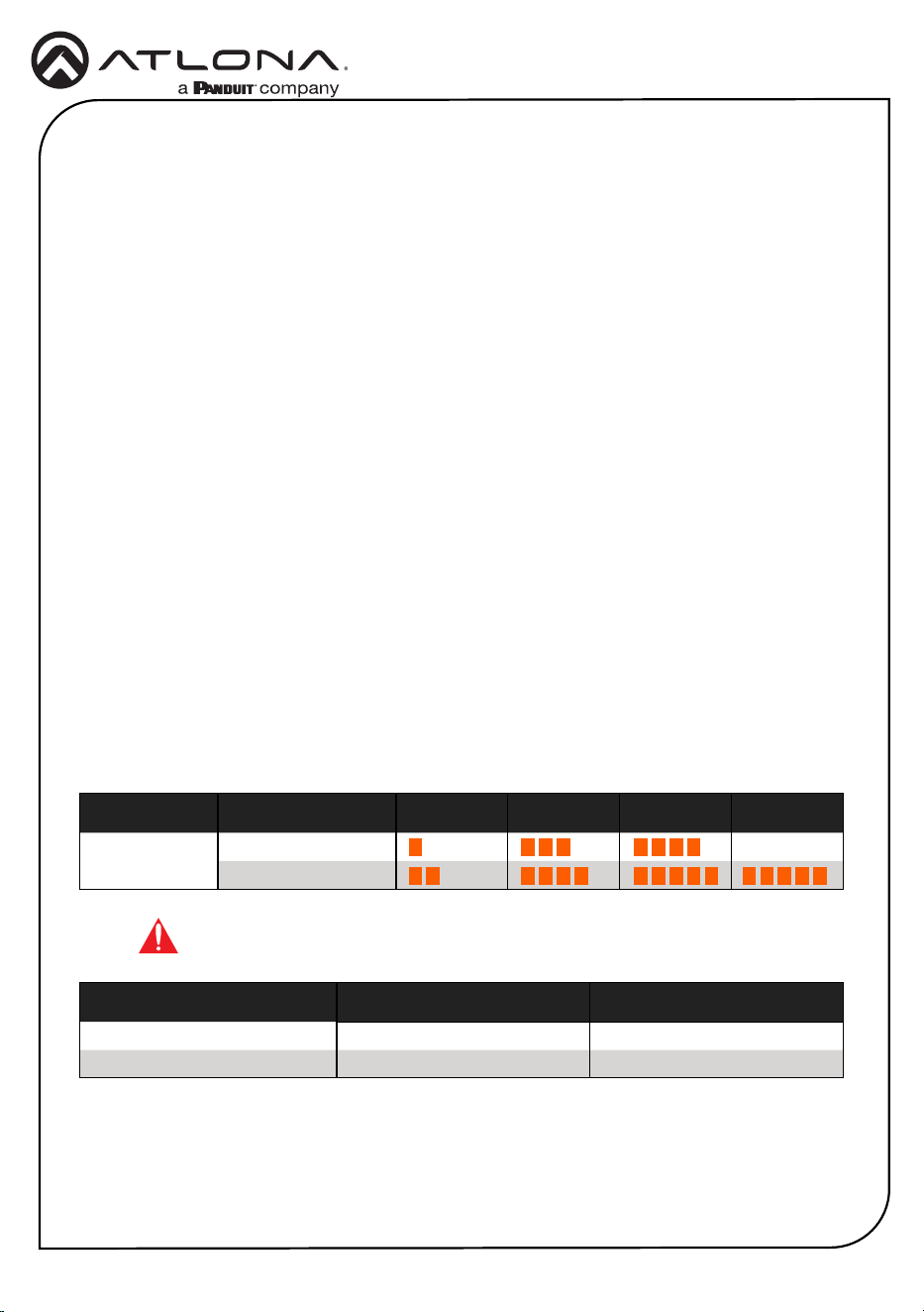
Refer to the tables below for recommended cabling when using Altona products with HDBaseT
technology. Higher-quality signals are represented by more bars. Performance may vary, based
on environmental factors.
Cable Recommendation Guidelines
Cable Max. Distance @ 4K Max. Distance @ 1080p
CAT5e 295 feet (90 meters) 330 feet (100 meters)
CAT6 / CAT6a / CAT7 330 feet (100 meters) 330 feet (100 meters)
IMPORTANT: Stranded or patch cables are not recommended due to
performance issues.
Core Shielding CAT5e CAT6 CAT6a CAT7
Solid UTP (unshielded) N/A
STP (shielded)
*Atlona recommends TIA/EIA 568-B termination for optimal performance.

Installation Guide
7
AT-OME-MS42-HDBT
Accessing the built-in Web Server
The AT-OME-MS42-HDBT includes a built-in web server, which allows easy remote management
and control of all features. Before the built-in web server can be used, a username and
password must be created.
1 Launch a web browser and enter the IP address of the unit.
2 The AT-OME-MS42-HDBT Register page will be displayed.
3 Enter the desired username in the Username eld.
4 Enter the desired password in the Password eld.
5 Verify the password by entering it in the Conrm eld.
6 Click the Submit button.
7 The Login screen will be displayed.
8 Enter the correct username and password in the respective elds.
9 Click the Submit button.
Static
If no DHCP server is available, or a static IP is required, the AT-OME-MS42-HDBT can be set to
static IP mode using the IP mode button.
• Press and hold the IP MODE button for 5 seconds to switch to static IP mode, the LED will
blink 2 times when it goes into Static IP mode. In this mode, the AT-OME-MS42-HDBT will
be set to the following:
IP address: 192.168.1.254
Subnet mask 255.255.0.0
Gateway: 192.168.1.1
• To switch back to DHCP, press and hold the IP mode button for 5 seconds. The LED will
blink 4 times when successfully put into DHCP mode.
DHCP
By default, the AT-OME-MS42-HDBT is set to DHCP mode. In this mode, when the AT-OME-
MS42-HDBT is connected to the Local Area Network (LAN), it will automatically be assigned an
IP address by the DHCP server (if available). Press the IP MODE button to show the IP address in
the top left corner of the display connected to the HDMI output.
IP Mode

Installation Guide
8
AT-OME-MS42-HDBT
Velocity
™
Device Manager
For easy conguration of Atlona devices, Velocity Device Manager is available from https://atlona.
com/ams for free.
Once Velocity Device Manager has been set up:
1 Open a browser on the same network as Velocity Device Manager and enter its IP address.
Refer to the Velocity Device Manager installation instructions on how to nd the IP address
of the software.
2. Enter the login information on the Velocity Device Manager web page, then click the Login
button.
3 View the AT-OME-MS42-HDBT manual for routing and conguration information.

Installation Guide
9
AT-OME-MS42-HDBT
Notes

Installation Guide
10
AT-OME-MS42-HDBT
Notes

Installation Guide
11
AT-OME-MS42-HDBT
Notes
Installation Guide
12
AT-OME-MS42-HDBT
25315-R1
®
The terms HDMI, HDMI High-Denition Multimedia Interface, HDMI trade dress and the HDMI Logos are
trademarks or registered trademarks of HDMI Licensing Administrator, Inc.
© 2024 Atlona Inc. All rights reserved. “Atlona” and the Atlona logo are registered trademarks of Atlona Inc. All other brand names and trademarks or registered
trademarks are the property of their respective owners. Pricing, specications and availability subject to change without notice. Actual products, product images,
and online product images may vary from images shown here.
English Declaration of Conformity
The English version can be found under the resources tab at:
https://atlona.com/product/ome-ms42-hdbt/.
Warranty
Chinese Declaration of Conformity 中国RoHS合格声明
To view the product warranty, use the following link or QR code:
https://atlona.com/warranty/.
由SKU列出於:
https://atlona.com/about-us/china-rohs/.
US International
atlona.com • 408.962.0515 • 41.43.508.4321