
WiFi Weather Station
Operation Manual
Model: WN1980
Table of Contents
1 Features .............................................................................................................3
2 Specification .....................................................................................................4
3 Connection between console and Wi-Fi Router ............................................... 4
4 Power on ...........................................................................................................5
4.1 Initial Display Console Set Up .................................................................... 5
4.2 Screen Display .............................................................................................7
5 Key ................................................................................................................... 8
5.1 Key function ................................................................................................ 8
5.2 Setting mode ................................................................................................ 9
5.3 Barometric Pressure Display ..................................................................... 11
5.3.1 Viewing Absolute vs. Relative Pressure ............................................. 11
5.3.2 Rate of Change of Pressure Graph ..................................................... 11
5.3.3 Relative Pressure Calibration Discussion ...........................................12
5.4 Rain Display .............................................................................................. 13
5.4.1 Rain Increments of Measure ...............................................................13
5.4.2 Increments of Rain Definitions .......................................................... 13
5.5 Wind Display ............................................................................................. 13
5.6 Temperature Display ..................................................................................14
5.6.1 Wind Chill, Dew Point and Heat Index Display ................................ 14
5.7 Alarms ........................................................................................................14
5.7.1 Viewing High and Low Alarms .......................................................... 14
5.7.2 Setting High and Low Alarms ............................................................ 15
5.8 Max/Min Mode ..........................................................................................18
5.8.1 Viewing Max/Min Values ...................................................................18
5.9 Resynchronize Wireless Sensor .................................................................20
5.10 Backlight Operation .................................................................................20
5.10.1 With USB cable (included) ...............................................................20
5.10.2 Without USB cable ........................................................................... 20
5.11 Tendency Arrows ..................................................................................... 21
5.12 Wireless Signal Quality Indicator ............................................................21
5.13 Weather Forecasting ................................................................................ 21
5.13.1 Storm Alert ....................................................................................... 22
5.13.2 Weather Forecasting Description and Limitations ........................... 22
6 Install & Wireless Communication ................................................................ 23
7 Troubleshooting Guide ................................................................................... 24
8 Warranty Information ..................................................................................... 26

*Please scan the QR code to read
English manual and keep it for
future reference
*
Bitte scannen Sie den QR-Code
zudeutsche Anleitung lesen und
aufbewahren füZukunftsbezug
*Si prega di scansionare il codice
QR perleggi il manuale italianoe
conservalo perReferenza futura
Instruction manuals
https://s.ecowitt.com/BHGPPM
Help
Our product is continuously changing and improving, particularly
online services and associated applications. To download the latest
manual and additional help, please contact our technical support team:
support@ecowitt.com
support.eu@ecowitt.net (EU/UK)
3
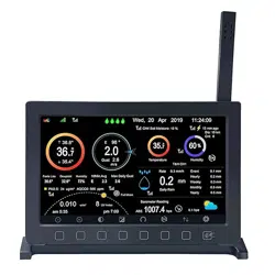
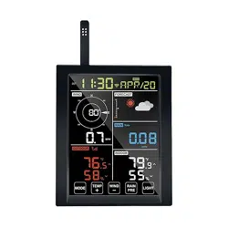
1 Features
Figure 1: Display console front and back
(1) Touch Key
(2) Wi-Fi ready, works with ecowitt weather service, WU, WOW and
custom server
(3) Sharp LCD display
(4) All ecowitt ecosystem sensors are supported for uploading to cloud
server, and on LCD it displays data for wind, rain, outdoor
temperature and humidity only. Those undisplay data can be viewed
via ecowitt APP or website dashboard.
(5) Additional/optional sensors:
Up to 8 WH31 multi-channel temperature and humidity
sensors Or 8 WN30 multi-channel temp sensors Or WN36
Pool Thermometer
Up to 8 WN34 Temperature Sensors
Up to 8 WN35 Leaf Wetness Sensor
Up to 4 WH41/WH43 PM2.5 air quality sensors
One WH45 PM2.5/PM10/CO2/temperature and humidity
all-in-1 sensor
Up to 8 WH51 soil moisture sensors
Up to 4 WH55 water leak sensors

4
One WH57 lightning sensor
One WH68 4-in-1 sensor Indoor temperature, indoor
humidity, wind direction and wind speed
One WN67 Outdoor Sensor Body with built-in:
Thermo-hygrometer / Rain Gauge / Wind Speed Sensor/
Wind Direction Sensor
One WS69 Outdoor Sensor Body with built-in:
Thermo-hygrometer / Rain Gauge / Wind Speed Sensor/
Wind Direction Sensor, Light and UV sensor, Solar panel
One WS80 Ultrasonic Anemometers with Temp &
Humidity sensor
One WS90 Ultrasonic Anemometer with Piezoelectric Rain
Gauge, Light & UV, Thermo-hygrometer Sensors
2 Specifications
Measurement
Range
Accuracy
Resolution
Barometric
300 to 1100 hPa
(8.85 to 32.5 inHg)
± 5hPa
0.1hPa (0.01
inHg)
Temperature
(Indoor)
-10°C to 60°C (14°F
to 140°F)
± 0.3°C (±
0.6°F)
0.1°C (0.1°F)
Humidity
(Indoor)
1% to 99%
± 3.5%
1%
Power supply: Type-C power cable
Backup power: 2 x AA batteries (Support Min. 48 hours working)
3 Connection between console and Wi-Fi Router
Transmission distance in open field: 30m (100ft.) depending on router
and environment
Wi-Fi Frequency: 2.4 GHz
WLAN: 802.11 b/g/n
5
4 Power on
Figure 2: Batteries or USB cord
(1) Unfold the desk stand and place it 5 to 10 feet away from the
outdoor sensor.
(2) Remove the battery door and insert 2 AA Alkaline batteries. Then
plug in USB cord for normal operation. Please note the primary use
of battery is for power cut back up purpose only, and always the
console need to be powered via USB power.
(3) Wait several minutes for the remote sensors to synchronize with the
display console.
(4) During normal operation, console will generate heat and cause
temperature rising. To prevent this heat up, the temperature and
humidity sensor is located at the foldable probe ends. To achieve
maximum accuracy reading, please unfold the probe and make sure
the sensor is further away from the main console body.
4.1 Initial Display Console Set Up
Upon power up the display console:
The unit will show sensor frequency under the wind direction graph and
software version number 2 seconds.
Then all segments of the LCD will be on for 3 seconds: check all LCD
segments are displayed correctly. After this, the unit will start to register
sensors for 3 minutes.
6
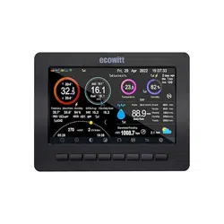
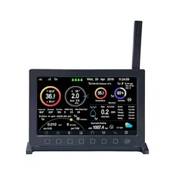
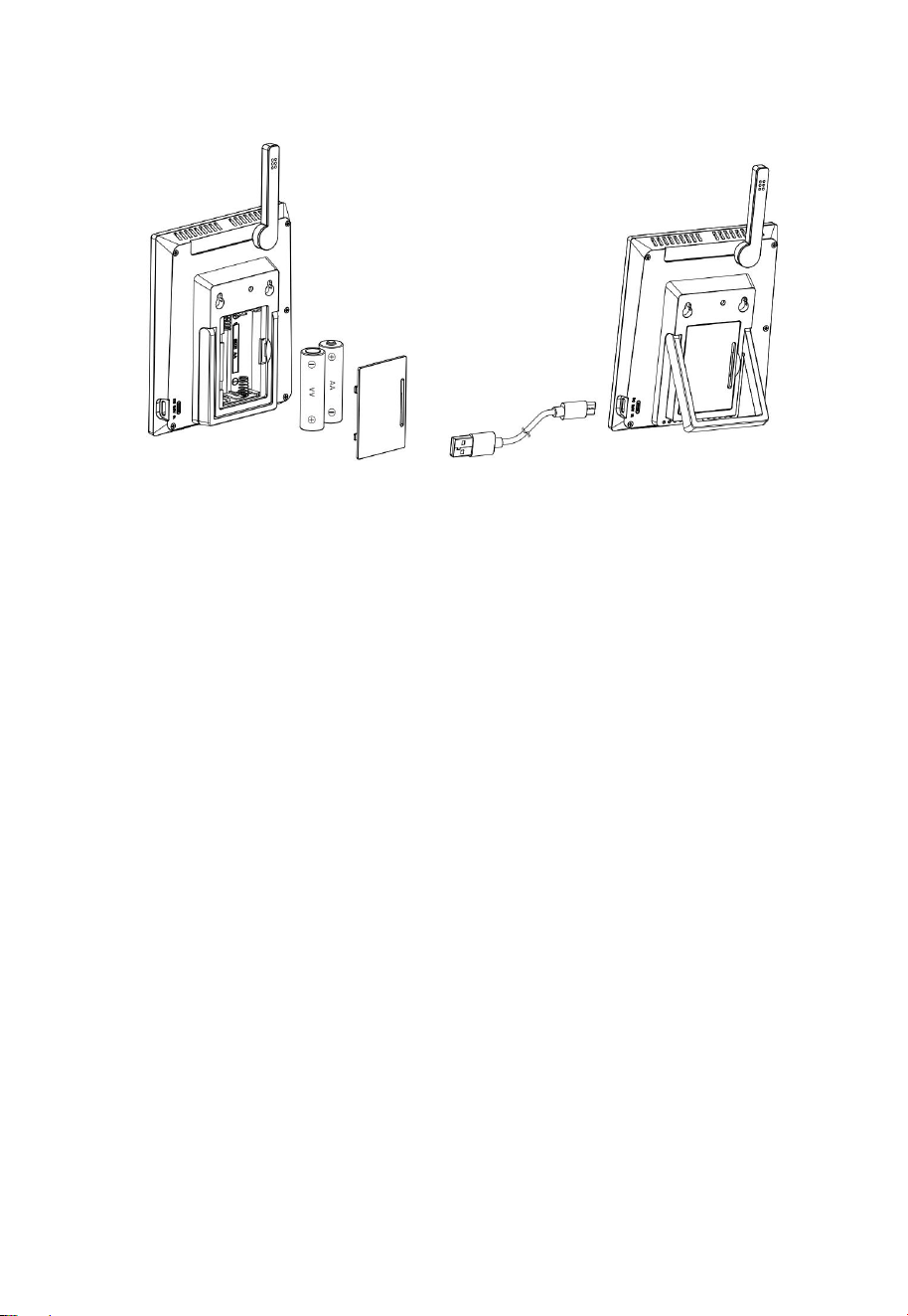
Figure 3: Display Console Screen Layout
Figure 4: Display Console Screen Layout
7
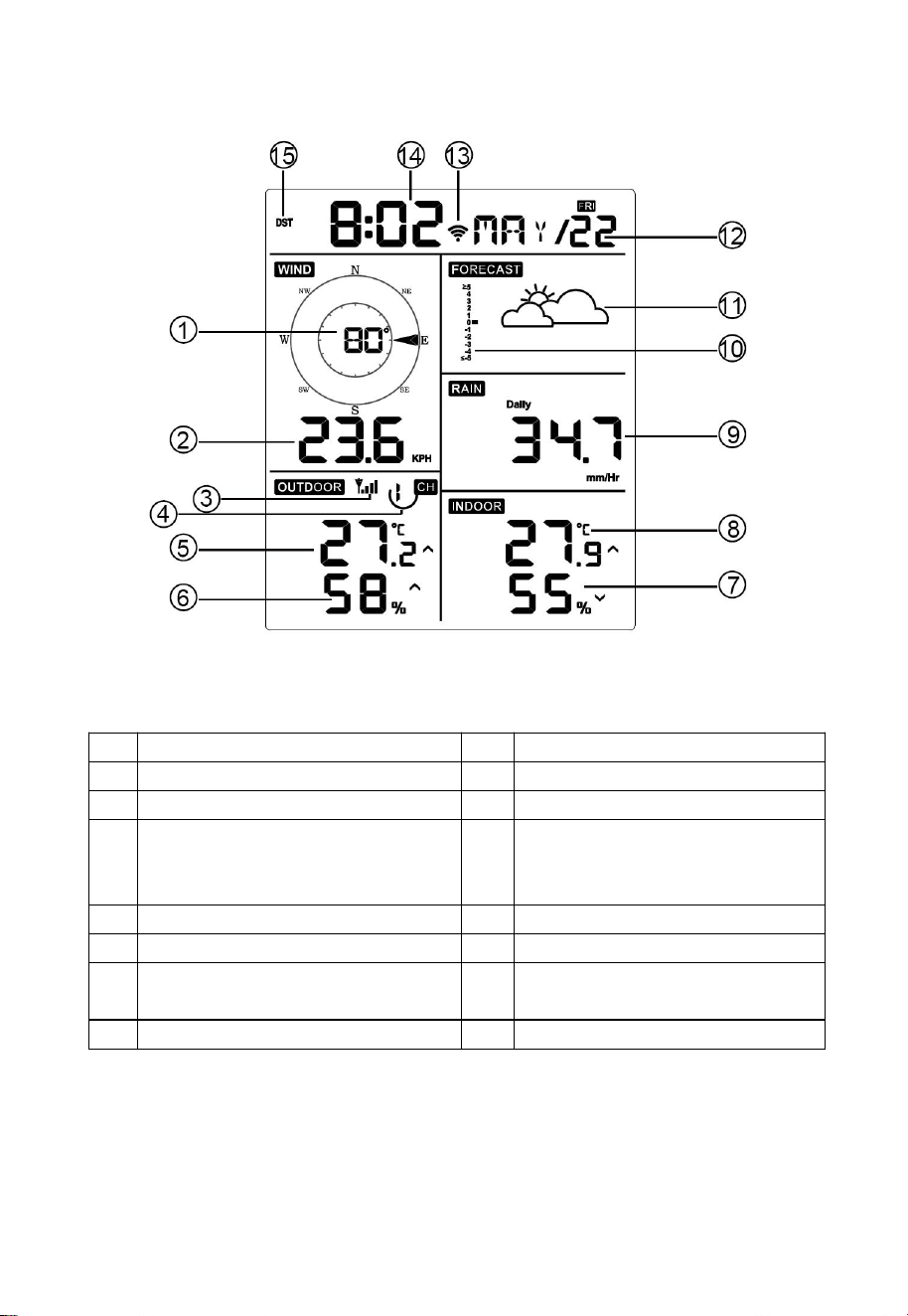
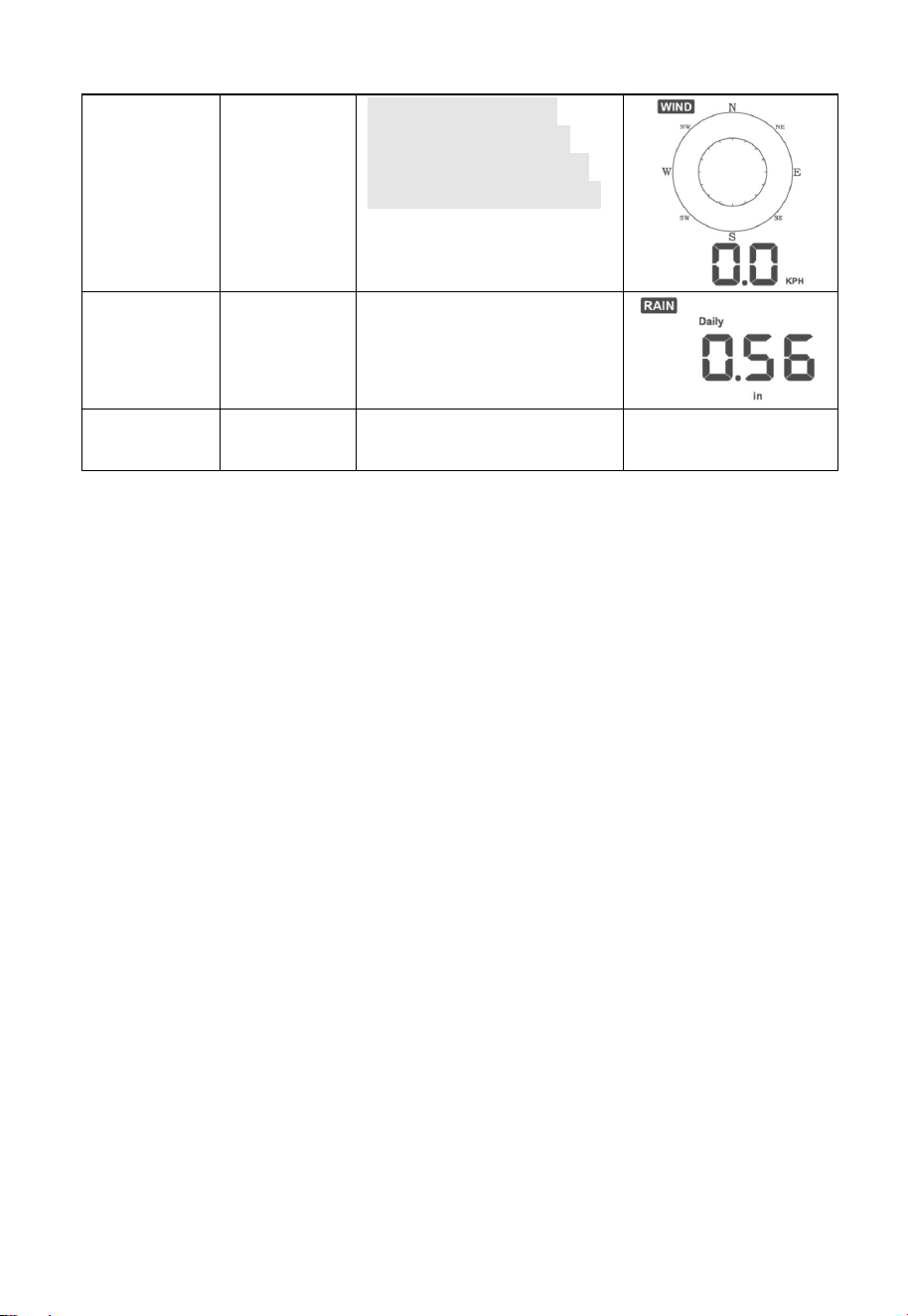
4.2 Screen Display
Figure 5: Display Console Screen Layout
1
Wind direction
9
Rainfall
2
Wind speed
10
Barometric Pressure graphic
3
RF icon
11
Weather forecast
4
8 Channel Indoor/Outdoor
Thermo-Hygrometer recycle
icon (optional)
12
Date
5
Outdoor temperature
13
WIFI icon
6
Outdoor humidity
14
Time
7
Indoor humidity
15
Daylight Savings Time
(DST)
8
Indoor temperature
Table 1: Display console detailed items
8
5 Key
5.1 Key function
The console has five keys for easy operation
Figure 6
Key
Description
MODE
Press and hold for two seconds to enter the Set
Mode.
Press to switch between Normal Mode, Max Mode,
Min Mode, High Alarm Mode, Low Alarm Mode,
MAC address display Mode
TEMP+
Press to switch between Outdoor Temperature, Wind
Chill, Dew Point, Heat Index, 8 channel optional
Indoor/Outdoor Thermo-hygrometer, Circle Mode
WIND -
Press to switch between average wind speed and,
wind gust.
Press and hold for two seconds to switch the wind
direction to display in degrees or in letters.
RAIN/PRE
Press and hold for two seconds switch between Rain
and Barometer.
While in Rain mode, press to switch between Rain
Rate, Rain Events, Hourly Rain, Daily Rain, Weekly
Rain, and Monthly Rain
While in Pressure mode, press to switch between
Relative pressure and Absolute pressure
LIGHT
Press to adjust the LCD backlight brightness (high,
medium and off).
Press to exit the SET mode at any time.
9
TEMP+
(and)
RAIN PRE
Press these two buttons at the same time for 4
seconds to activate Wi-Fi configuration mode (refer
to section 8.1.2)
Table 2: Key function
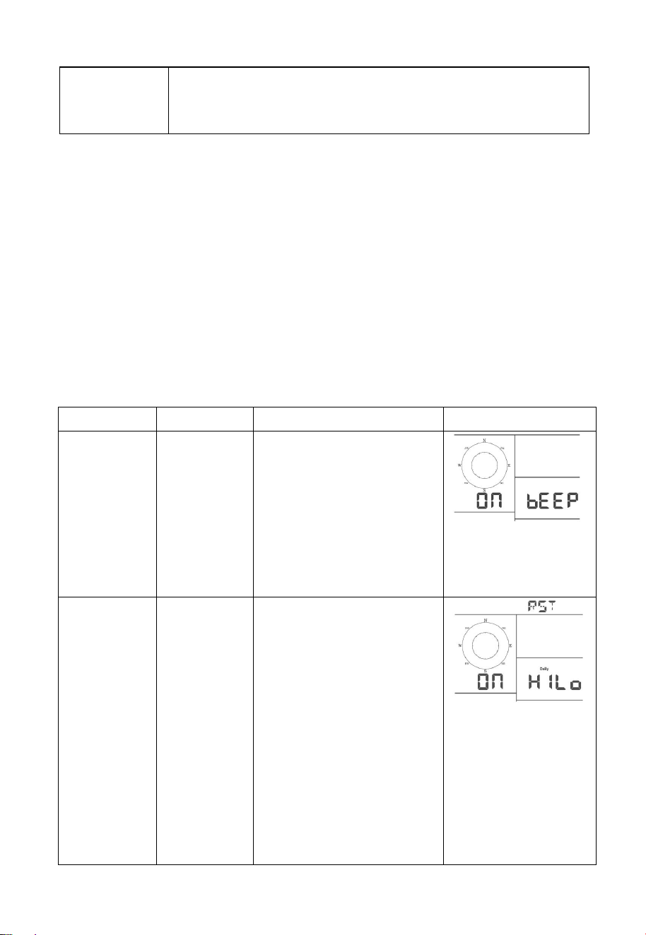
5.2 Setting mode
Note: DST, Time Zone setting can only be realized via ECOWITT APP.
You will need to set time zone and DST properly if you have the console
connected to internet.
Press and hold the MODE button for two seconds to enter the Set Mode.
To proceed to the next setting, press (do not hold) the MODE button.
To exit the SET mode at any time, press the LIGHT button.
Table 8 summarizes the set mode sequence and commands.
Command
Mode
Settings
Image
[MODE] +
2 seconds
Enter Set
Mode,
Beep On or
Off
Press [TEMP +] or
[WIND -] to switch OFF
and ON.
This will prevent the
beep from sounding
when pressing any
button.
[MODE]
Clear
Max/Min
Press [TEMP +] or
[WIND -] to switch OFF
and ON.
When set to ON, the
minimum and maximum
values reset every day at
midnight (00:00).
When set to OFF, the
minimum and maximum
values must be reset
manually.
10
[MODE]
12 hour /
24 Hour
Format
Press [TEMP +] or
[WIND -] to switch hour
format between 12 hour
and 24-hour format.
[MODE]
Hour
Press [TEMP +] or
[WIND -] to adjust hour
up or down.
[MODE]
Minute
Press [TEMP +] or
[WIND -] to adjust
minute up or down.
[MODE]
Year
Press [TEMP +] or
[WIND -] to adjust year
up or down
[MODE]
Month
Press [TEMP +] or
[WIND -] to adjust
month up or down
[MODE]
Day
Press [TEMP +] or
[WIND -] to adjust day
up or down
[MODE]
Pressure
Units of
Measure
Press [TEMP +] or
[WIND -] to change
units of measure
between hap, mmHg or
inHg.
[MODE]
Relative
Pressure
Calibration
Press [TEMP +] or
[WIND -] to adjust
relative pressure up or
down
Reference Section 6.4.3
for details on calibration
of relative pressure.
[MODE]
Temperatur
e Units of
Measure
Press [TEMP +] or
[WIND -] to change
temperature units of
measure between °F
and °C.
11
[MODE]
Wind Units
of Measure
Press [TEMP +] or
[WIND -] to change
wind units of measure
between km/h and mph.
[MODE]
Rain Units
of Measure
Press [TEMP +] or
[WIND -] to change rain
units of measure
between in and mm.
[MODE]
Exit Set
Mode
[MODE] + 2 seconds means press and hold the MODE button for
two seconds.
[MODE] means press the MODE button.
Table 3: Set mode sequence and commands summarization
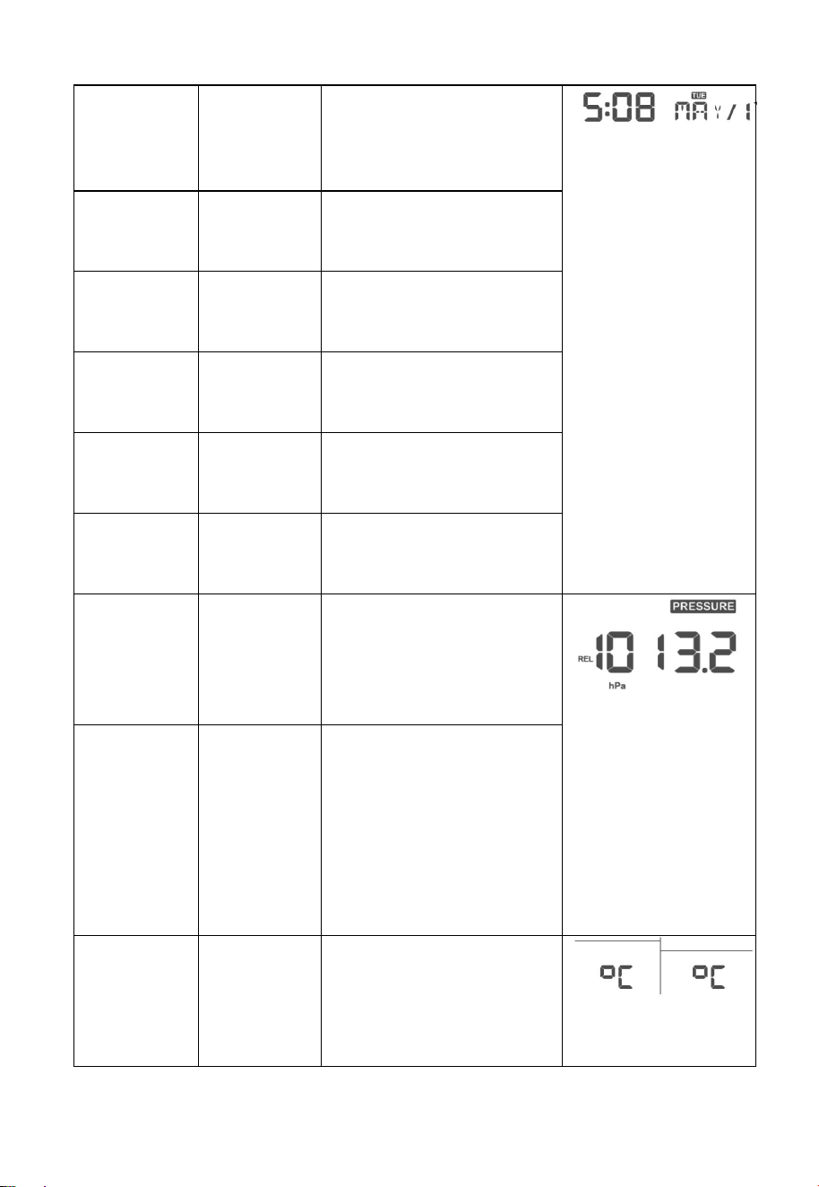
5.3 Barometric Pressure Display
5.3.1 Viewing Absolute vs. Relative Pressure
Press and hold [RAIN/PRE] for two seconds switch between Rain and
Pressure. While in Pressure mode Press [RAIN/PRE] to switch between
absolute and relative pressure
Absolute pressure is the measured atmospheric pressure, and is a function
of altitude, and to a lesser extent, changes in weather conditions.
Absolute pressure is not corrected to sea-level conditions.
Relative pressure is corrected to sea-level conditions. For further
discussion of relative pressure and calibration, reference Section 6.4.3.
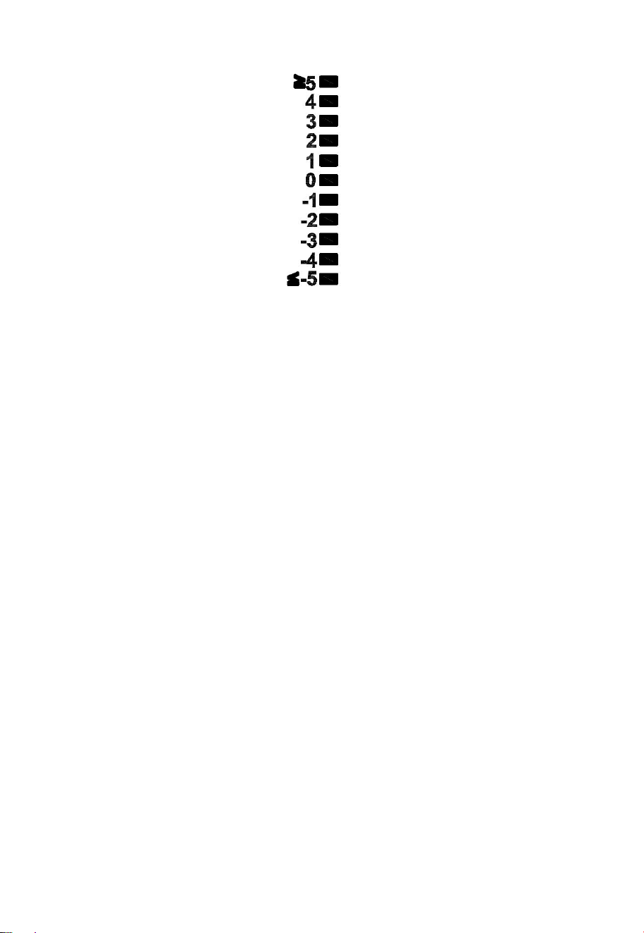
5.3.2 Rate of Change of Pressure Graph
The rate of change of pressure graphic is shown to the left of the weather
forecast icons and signifies the difference between the daily average
pressure and the 30-day average (in hPa).
12
Figure 7
5.3.3 Relative Pressure Calibration Discussion
The calibration can be realized on ECOWITT app by going to “sensor”
page, and you can find the console of WN1980 to start with. To compare
pressure conditions from one location to another, meteorologists correct
pressure to sea-level conditions. Because the air pressure decreases as
you rise in altitude, the sea-level corrected pressure (the pressure your
location would be at if located at sea-level) is generally higher than your
measured pressure.
Thus, your absolute pressure may read 28.62 inHg (969 mb) at an altitude
of 1000 feet (305 m), but the relative pressure is 30.00 inHg (1016 mb).
The standard sea-level pressure is 29.92 inHg (1013 mb). This is the
average sea-level pressure around the world. Relative pressure
measurements greater than 29.92 inHg (1013 mb) are considered high
pressure and relative pressure measurements less than 29.92 inHg are
considered low pressure.
To determine the relative pressure for your location, locate an official
reporting station near you (the internet is the best source for real time
barometer conditions, such as Weather.com or Wunderground.com), and
set your weather station to match the official reporting station.

13
5.4 Rain Display
5.4.1 Rain Increments of Measure
Press and hold [RAIN/PRE] for two seconds switch between Rain and
Pressure. While in Rain mode press [RAIN/PRE] button to switch
between Rain Rate (in/hr), Rain Event, Rain Hourly, Daily Rain, Weekly
Rain, Monthly Rain and Yearly Rain.
5.4.2 Increments of Rain Definitions
Rain rate or hourly rain is defined as the last 10 minutes of rainfall
sum total and multiplied by six (10 minutes x 6 = 1 hour). This is also
referred to as instantaneous rain per hour.
Rain event is defined as continuous rain, and resets to zero if rainfall
accumulation is less than 1 mm (0.039 in) in a 24-hour period.
Daily Rain is defined as the rainfall since midnight (00:00).
Weekly Rain is defined as the calendar week total and resets on
Sunday morning at midnight (Sunday thru Saturday).
Monthly Rain is defined as the calendar month total and resets on
the first day of the Month.
Yearly Rain is defined as the calendar year i.e. January 1- December
31
5.5 Wind Display
Press the [WIND -] button to switch between average wind speed and,
wind gust.
Press and hold the [WIND -] button for two seconds to switch the wind
direction to display in degrees or in letters.
Wind speed is defined as the average wind speed in the 16 second
update period.
Wind gust is defined as the peak wind speed in the 16 second update
period.
14
5.6 Temperature Display
If temperature is lower than minimum range, the temperature field will
display dashes (--.-).
If temperature is higher than maximum range, the temperature field will
display dashes (--.-).
5.6.1 Wind Chill, Dew Point and Heat Index Display
Press the [TEMP] button to switch between Outdoor Temperature, Wind
Chill, Dew Point, Heat Index.
The device supports up to 8 additional thermo-hygrometer sensors
(WH31). If you have the extra sensors, press the [TEMP +] button to
switch between Outdoor Temperature, Wind Chill, Dew Point, Heat Index,
8 channel temperature and humidity, Circle Mode
5.7 Alarms
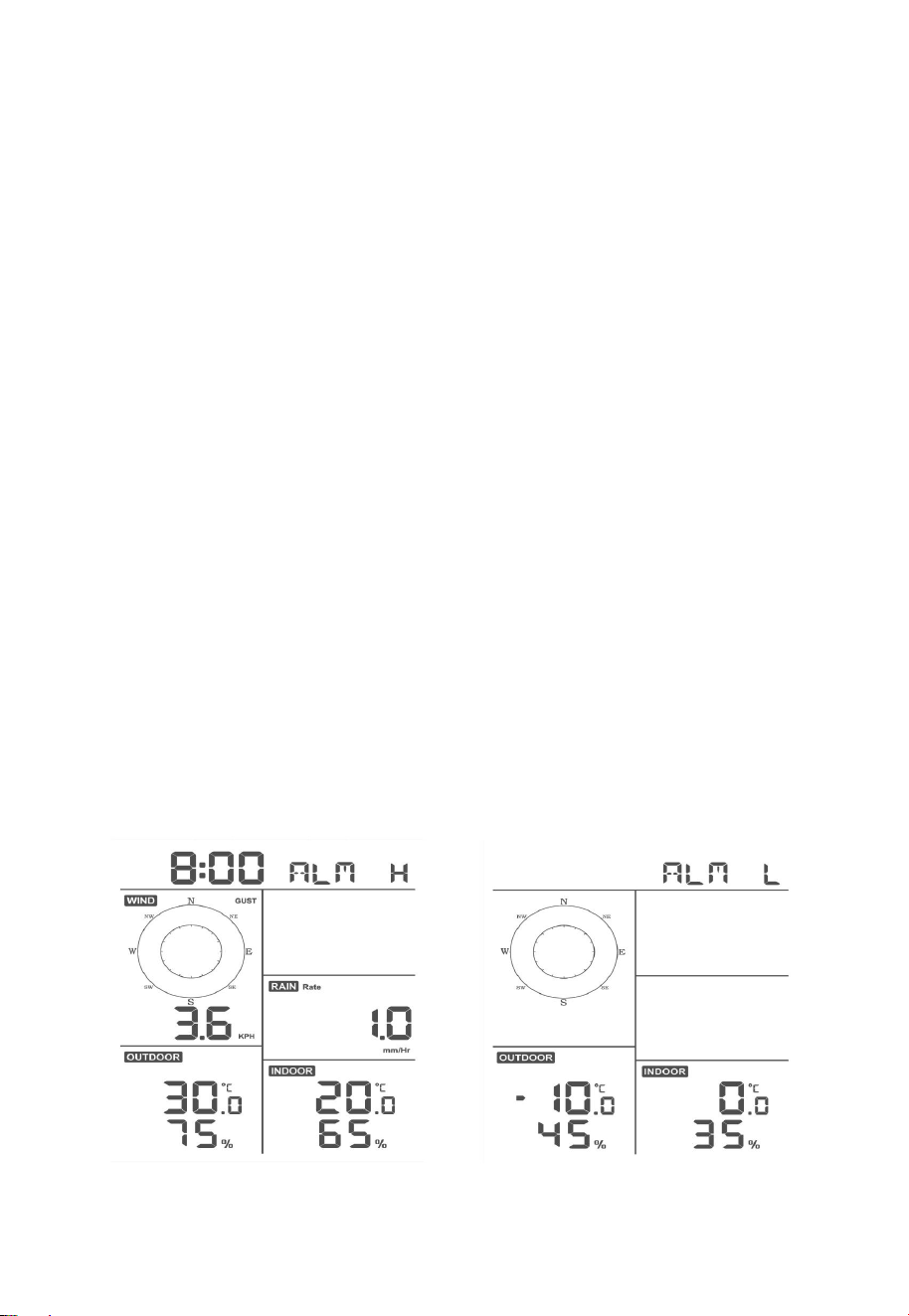
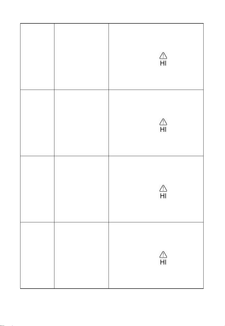
5.7.1 Viewing High and Low Alarms
To view the high alarm settings, press MODE button a third time, and the
high alarms will be displayed, as shown in Figure 8 (a).
To view the low alarm settings, press the MODE button a fourth time,
and the low alarms will be displayed, as shown in Figure 8 (b).
To return to normal mode, press the LIGHT button again.
(a)
(b)
Figure 8
15
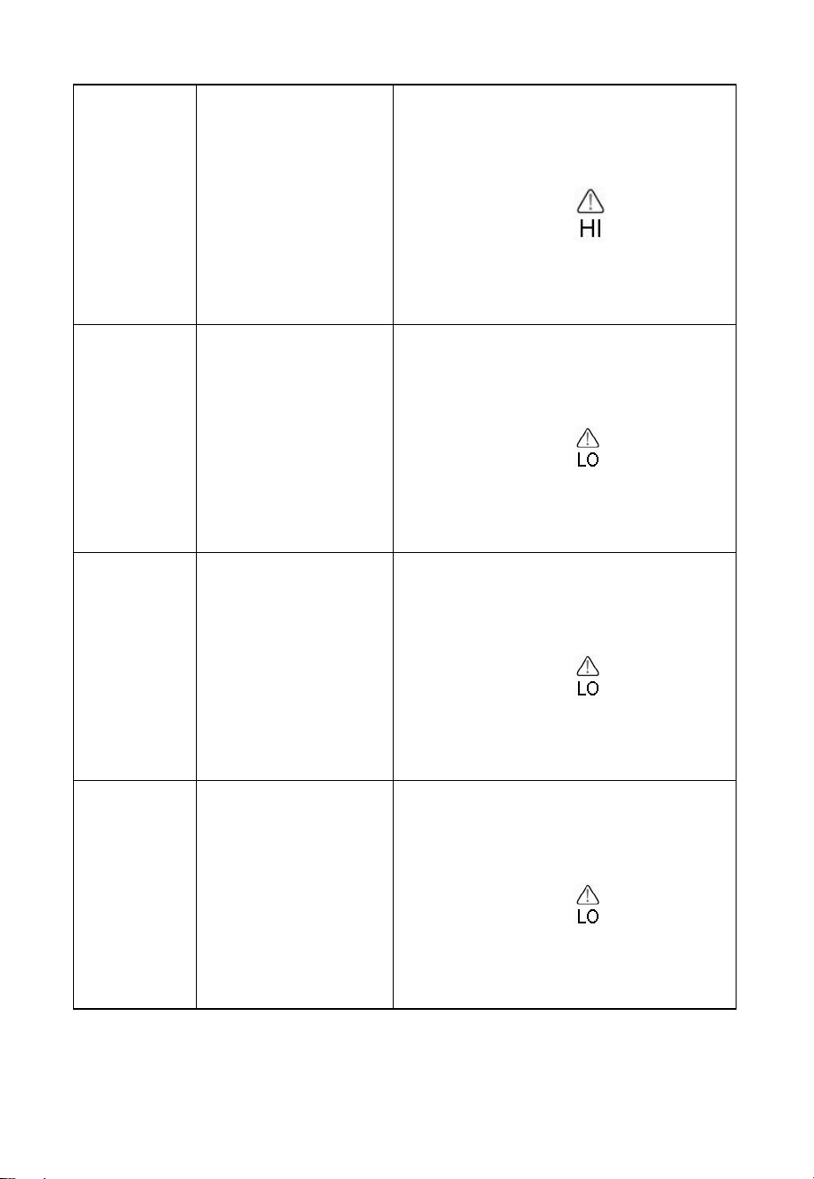
5.7.2 Setting High and Low Alarms
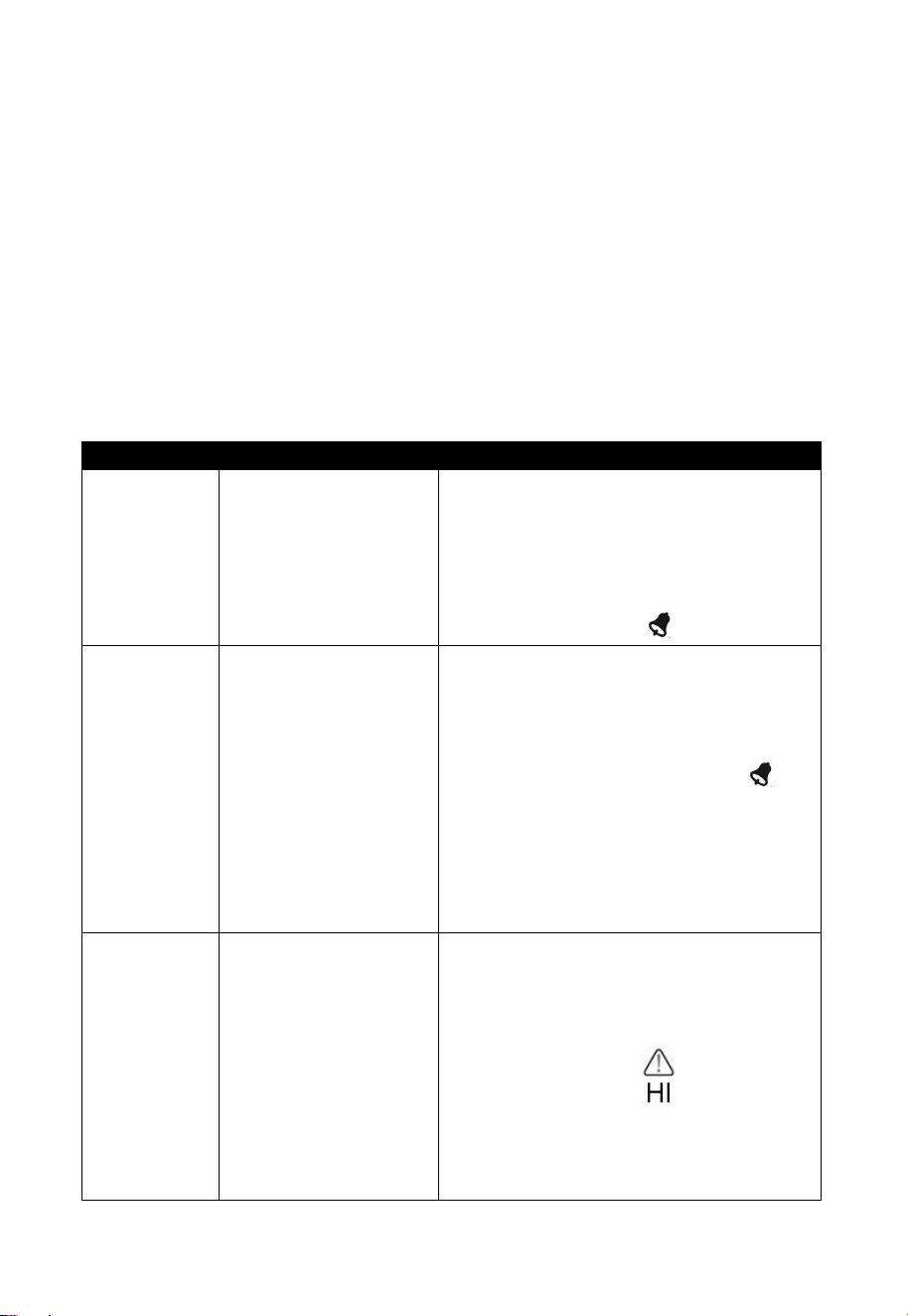
While the High Alarm is displayed (reference Section 6.8.1), press and
hold the MODE button for 2 seconds to enter the High Alarm Set Mode.
While the Low Alarm is displayed (reference Section 6.8.1), press and
hold the MODE button for 2 seconds to enter the Low Alarm Set Mode.
To save and proceed to the next alarm setting, press the Mode button.
To exit the High Alarm Set Mode at any time, press the LIGHT button.
Table 9 summarizes the alarm mode sequence and commands.
Command
Mode
Settings
[MODE] +
2 seconds
Enter High Alarm
Set Mode, Alarm
Hour
Press [TEMP +] or [WIND -] to adjust
alarm hour up or down.
Press [RAIN/PRE] to turn the time
alarm on or off. When the alarm is on,
the alarm time icon will appear.
[MODE]
Alarm Minute
Press[TEMP +] or [WIND -] to adjust
alarm minute up or down.
Press [RAIN/PRE] to turn the time
alarm on. The alarm time icon
will appear.
Press [RAIN/PRE] again to turn the
time alarm off. The alarm time icon
will disappear.
[MODE]
Alarm High Indoor
Temperature
Press [TEMP +] or [WIND - ]to adjust
alarm value up or down.
Press [RAIN/PRE] to turn the alarm
on. The alarm icon will appear.
Press [RAIN/PRE] to turn the alarm
off. The alarm icon will disappear.
16
[MODE]
Alarm High Indoor
Humidity
Press [TEMP +] or [WIND -] to adjust
alarm value up or down.
Press [RAIN/PRE] to turn the alarm
on. The alarm icon will appear.
Press [RAIN/PRE] to turn the alarm
off. The alarm icon will disappear.
[MODE]
Alarm High Outdoor
Temperature
Press[TEMP +] or [WIND -] to adjust
alarm value up or down.
Press [RAIN/PRE] to turn the alarm
on. The alarm icon will appear.
Press [RAIN/PRE] to turn the alarm
off. The alarm icon will disappear.
[MODE]
Alarm High Outdoor
Humidity
Press [TEMP +] or [WIND -] to adjust
alarm value up or down.
Press [RAIN/PRE] to turn the alarm
on. The alarm icon will appear.
Press [RAIN/PRE] to turn the alarm
off. The alarm icon will disappear.
[MODE]
Alarm High Wind
Gust
Press [TEMP +] or [WIND -] to adjust
alarm value up or down.
Press [RAIN/PRE] to turn the alarm
on. The alarm icon will appear.
Press [RAIN/PRE] to turn the alarm
off. The alarm icon will disappear.
17
[MODE]
Alarm High Rain
Rate
Press [TEMP +] or [WIND -] to adjust
alarm value up or down.
Press [RAIN/PRE] to turn the alarm
on. The alarm icon will appear.
Press [RAIN/PRE] to turn the alarm
off. The alarm icon will disappear.
[MODE]
Alarm Low Indoor
Temperature
Press [TEMP +] or [WIND - ]to adjust
alarm value up or down.
Press [RAIN/PRE] to turn the alarm
on. The alarm icon will appear.
Press [RAIN/PRE] to turn the alarm
off. The alarm icon will disappear.
[MODE]
Alarm Low Indoor
Humidity
Press [TEMP +] or [WIND -] to adjust
alarm value up or down.
Press [RAIN/PRE] to turn the alarm
on. The alarm icon will appear.
Press [RAIN/PRE] to turn the alarm
off. The alarm icon will disappear.
[MODE]
Alarm Low Outdoor
Temperature
Press[TEMP +] or [WIND -] to adjust
alarm value up or down.
Press [RAIN/PRE] to turn the alarm
on. The alarm icon will appear.
Press [RAIN/PRE] to turn the alarm
off. The alarm icon will disappear.
18
[MODE]
Alarm Low Outdoor
Humidity
Press [TEMP +] or [WIND -] to adjust
alarm value up or down.
Press [RAIN/PRE] to turn the alarm
on. The alarm icon will appear.
Press [RAIN/PRE] to turn the alarm
off. The alarm icon will disappear.
[MODE]
Exit alarm settings
mode.
[MODE] + 2 seconds means press and hold the ALARM button for 2
seconds.
[MODE] means press the MODE button.
Table 4: Alarm mode sequence and commands summarization
5.8 Max/Min Mode
5.8.1 Viewing Max/Min Values
To view the max value, press the MODE button, and the max values will
be displayed, as shown in Figure 9 (a). To clear the max values, press and
hold the MODE button while the max values are displayed.
To view the low alarm settings, press the MODE button again, and the
min values will be displayed, as shown in Figure 9 (b). To clear the min
values, press and hold the MODE button while the min values are
displayed.
To return to normal mode, press the LIGHT button.
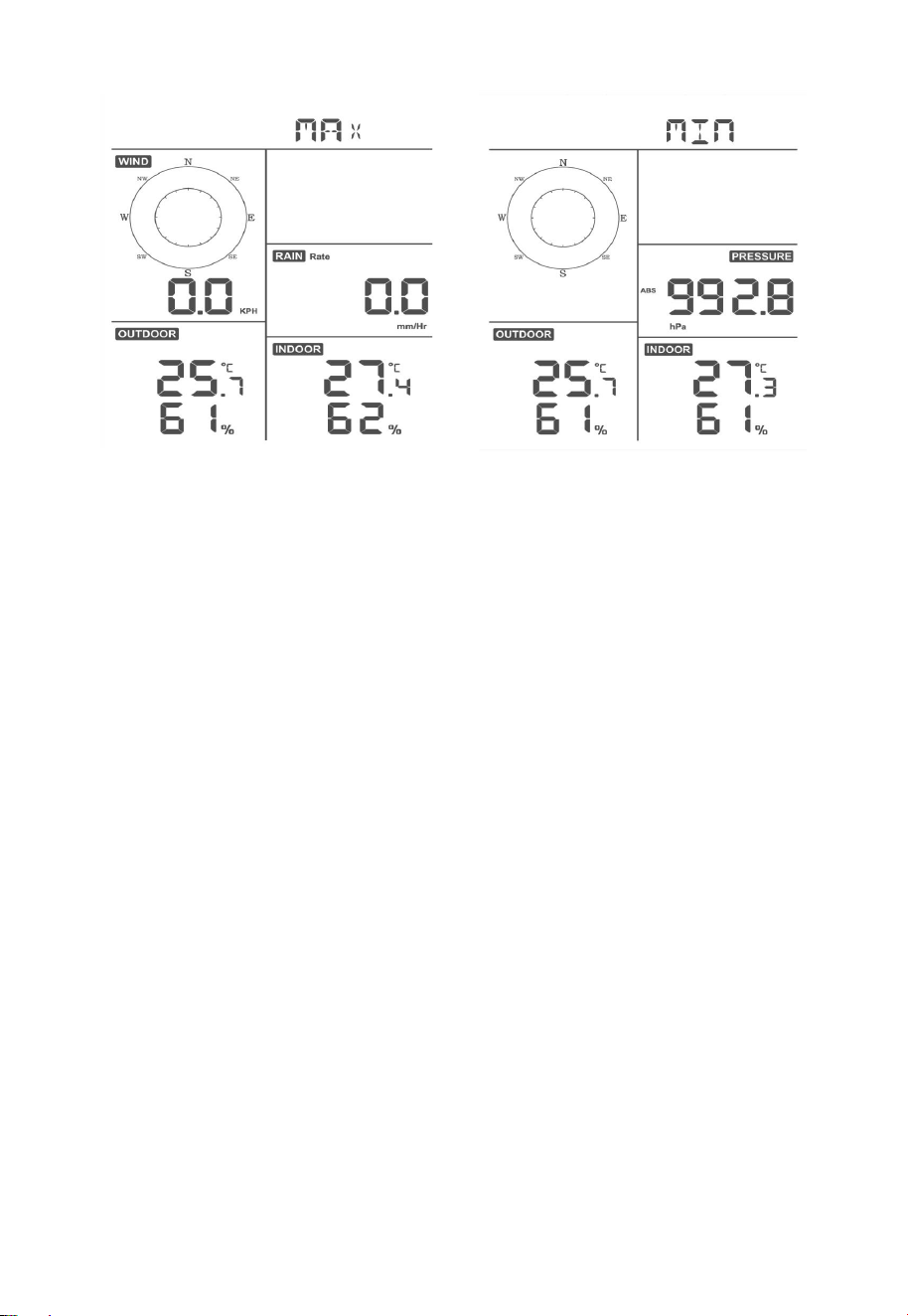
19
(a)
(b)
Figure 9
5.8.1.1 Display Wind Chill, Heat Index vs. Dew Point Max/Min
Values
While the max values are displayed as outlined in Section 6.9.1, press the
TEMP+ button once to view the wind chill, twice to view the dew point,
third to view the heat index and a fourth time to return to outdoor
temperature.
While the min values are displayed as outlined in Section 6.9.1, press the
TEMP+ button once to view the wind chill, twice to view the dew point,
third to view the heat index and a fourth time to return to outdoor
temperature.
5.8.1.2 Display Wind Speed vs. Wind Gust Max Values
While the max values are displayed as outlined in Section 6.9.1, press the
WIND- button once to view the max wind gust, and twice to return to
wind speed.
5.8.1.3 Display Hourly Rain, Rain Rate
While the max values are displayed as outlined in Section 6.9.1, press the
RAIN button once to view the max hourly rain, twice to view the rain
rate.

20
5.8.1.4 Display Absolute and Relative Pressure Min and Max
Values
While the max values are displayed as outlined in Section 6.9.1, press
and hold the RAIN/PRE button for two seconds to enter pressure display,
press RAIN/PRE button to switch between Relative pressure and
Absolute pressure.
While the min values are displayed as outlined in Section 6.9.1, press
and hold the RAIN/PRE button for two seconds to enter pressure display,
press RAIN/PRE button to switch between Relative pressure and
Absolute pressure.
To return to normal mode, press the LIGHT button.
5.9 Resynchronize Wireless Sensor
While in outdoor TH/wind chill/dew point/heat index display mode press
TEMP+ button for 5 seconds, and the console will re-register the outdoor
sensor array.
While in 1-8 channel Thermo-hygro sensor display mode press TEMP+
button for 5 seconds, and the console will re-register the current channel
outdoor sensor.
While in Circle Mode press TEMP+ button for 5 seconds, and the
console will re-register the sensor array and 1-8 channel sensors.
5.10 Backlight Operation
5.10.1 With USB cable (included)
The backlight can only be continuously on when the console display is
powered via USB.
Press the LIGHT button to adjust the brightness between High, Low and
Off.
5.10.2 Without USB cable
Press any button to turn on the backlight temporarily for 15 seconds.
21
5.11 Tendency Arrows
Tendency arrows allow you to quickly determine of temperature or
pressure are rising and falling in a three-hour update period, updated
every 30 minutes.
Table 10 defines the conditions for rising and falling pressure every 3
hours.
Tendency
indicators
Condition
Humidity Change
per 3 Hours
Temperature
Change per 3 Hours
︿
Rising
Rising > 3%
Rising > 1º C / 2 ºF
﹀
Falling
Falling > 3%
Falling > 1º C / 2 ºF
Table 5: Tendency indicators summarization
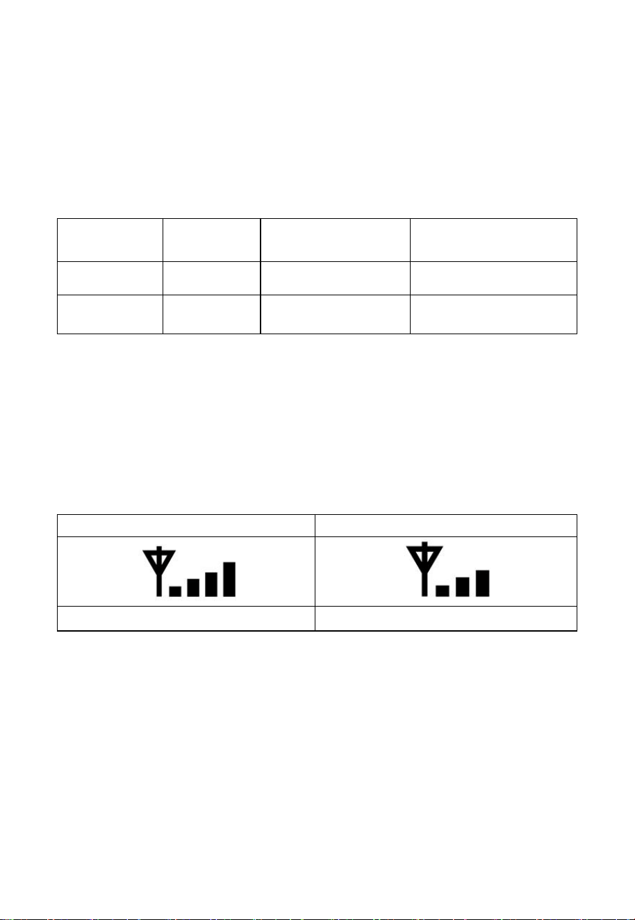
5.12 Wireless Signal Quality Indicator
The wireless signal strength displays reception quality. If no signal is lost,
the signal strength indicator will display 4 bars. If the signal is lost once,
four bars will be displayed, as shown in Table 6.
Four Bars
Three Bars
No signal loss
Lost signal once
Table 6
5.13 Weather Forecasting
The five weather icons are Sunny, Partly Cloudy, Cloudy, Rainy, Stormy
and Snowy.
The forecast icon is based on the rate of change of barometric pressure.
Please allow at least one month for the weather station to learn the
barometric pressure over time.
22
Sunny
Partly Cloudy
Cloudy
Rainy
Snowy
Pressure
increases for
a sustained
period of
time
Pressure
increases
slightly, or
initial power
up
Pressure
decreases
slightly
Pressure
decreases for
a sustained
period of
time
Pressure
decreases for
a sustained
period of time
and
temperature is
below
freezing
Table 7: Weather forecasting summarization
5.13.1 Storm Alert
If there is a rapid drop in barometric pressure, the forecast icon will flash.
5.13.2 Weather Forecasting Description and Limitations
In general, if the rate of change of pressure increases, the weather is
generally improving (sunny to partly cloudy). If the rate of change of
pressure decreases, the weather is generally degrading (cloudy, rainy). If
the rate of change is relatively steady, it will read partly cloudy.
The reason the current conditions do not match the forecast icon is
because the forecast is a prediction 24-48 hours in advance. In most
locations, this prediction is only 70% accurate and it is a good idea to
consult the National Weather Service for more accurate weather forecasts.
In some locations, this prediction may be less or more accurate. However,
it is still an interesting educational tool for learning why the weather
changes.
The National Weather Service (and other weather services such as
Accuweather and The Weather Channel) have many tools at their
disposal to predict weather conditions, including weather radar, weather
models, and detailed mapping of ground conditions.

23
6 Install & Wireless Communication
Note: To insure proper communication, mount the remote sensor(s)
upright on a vertical surface, such as a wall. Do not lay the sensor flat.
Wireless communication is susceptible to interference, distance, walls
and metal barriers. We recommend the following best practices for
trouble free wireless communication.
Electro-Magnetic Interference (EMI). Keep the console several feet
away from computer monitors and TVs.
Radio Frequency Interference (RFI). If you have other devices
operating on the same frequency band as your indoor and/or outdoor
sensors and experience intermitted communication between sensor and
console, try turning off these other devices for troubleshooting purposes.
You may need to relocate the transmitters or receivers to avoid
intermittent communication.
1. Line of Sight Rating. This device is rated at 300 feet line of sight
(no interference, barriers or walls) but typically you will get 100 feet
maximum under most real-world installations, which include passing
through barriers or walls.
2. Metal Barriers. Radio frequency will not pass through metal
barriers such as aluminum siding. If you have metal siding, align the
remote and console through a window to get a clear line of sight.
The following is a table of reception loss vs. the transmission medium.
Each “wall” or obstruction decreases the transmission range by the factor
shown below.
Medium
RF Signal Strength Reduction
Glass (untreated)
5-15%
Plastics
10-15%
Wood
10-40%
Brick
10-40%
Concrete
40-80%
Metal
90-100%
Table 8: RF Signal Strength reduction

24
7 Troubleshooting Guide
Problem
Solution
Outdoor sensor
array does not
communicate to
the display
console.
The sensor array may have initiated properly and
the data is registered by the console as invalid,
and the console must be reset. Press the reset
button as described in Section 5.2.
With an open ended paperclip, press the reset
button for 3 seconds to resync the console with the
sensor array about 10 feet away.
The LED next to the battery compartment will
flash every 16 seconds. If the LED is not flashing
every 16 seconds…
Replace the batteries in the outside sensor array.
If the batteries were recently replaced, check the
polarity. If the sensor is flashing every 16 seconds,
proceed to the next step.
There may be a temporary loss of communication
due to reception loss related to interference or
other location factors,
or the batteries may have been changed in the
sensor array and the console has not been reset.
The solution may be as simple as powering down
and up the console (remove AC power and
batteries, wait 10 seconds, and reinsert AC power
and batteries).
Temperature
sensor reads too
high in the day
time.
Make certain that the sensor array is not too close
to heat generating sources or strictures, such as
buildings, pavement, walls or air conditioning
units.
Use the calibration feature to offset installation
25
Problem
Solution
issues related to radiant heat sources. Reference
Section 10.6.
Relative pressure
does not agree with
official reporting
station
You may be viewing the absolute pressure, not the
relative pressure.
Select the relative pressure. Make sure you
properly calibrate the sensor to an official local
weather station. Reference Section 6.4.3 for
details.
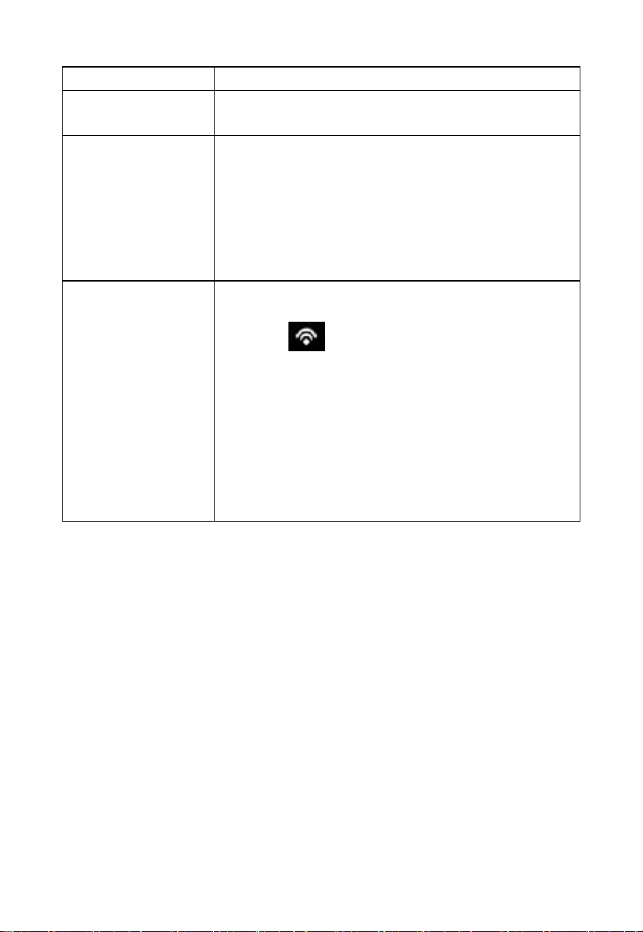
No WiFi
connection
1. Check for WiFi symbol on the display. If
wireless connectivity is successful the WiFi
icon will be displayed in the time field.
2. Make sure your modem WiFi settings are
correct (network name, and password).
3. The console only supports and connects to 2.4
GHz routers. If you own a 5 GHz router, and
it is a dual band router, you will need to
disable the 5 GHz band, and enable the 2.4
GHz band.
4. The console does not support guest networks.

26
8 Warranty Information
We disclaim any responsibility for any technical error or printing error, or
their consequences.
All trademarks and patents are recognized.
We provide a 1-year limited warranty on this product against
manufacturing defects in materials and workmanship.
This limited warranty begins on the original date of purchase, is valid
only on products purchased and only to the original purchaser of this
product. To receive warranty service, the purchaser must contact us for
problem determination and service procedures.
This warranty covers only actual defects within the product itself, and
does not cover the cost of installation or removal from a fixed installation,
normal set-up or adjustments, claims based on misrepresentation by the
seller or performance variations resulting from installation-related
circumstances.