Diagram References
3
3
1 2
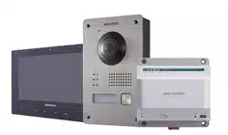
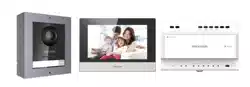
DS-KIS702Y(-P)
KD8003Y-IME2
Two-Wire Module Door Station
Video Intercom Two-Wire Kit
UD29996B
Scan the QR code to get User Manual for details.
Recommended Installation Height (The distance
between the camera and the ground): 1.4 m to 1.6 m
4
1.5 m
1.4 m
Gang Box
1 2 3 4
5
Expansion Bolt
Moun�ng Ear
Main Unit
Sub Module 1
Sub Module 2
Hexagonal
Screw
1
2
2
2
1
3
3
3
1
2 3
4
5
Module-Connec�ng
Line1
Module-Connec�ng
Line2
Thread Hole
Cables
Connected
to Main
Unit
Main Unit
Sub Module
Moun�ng Frame
Hexagonal
Screw
Cover
Hexagon Wrench
1
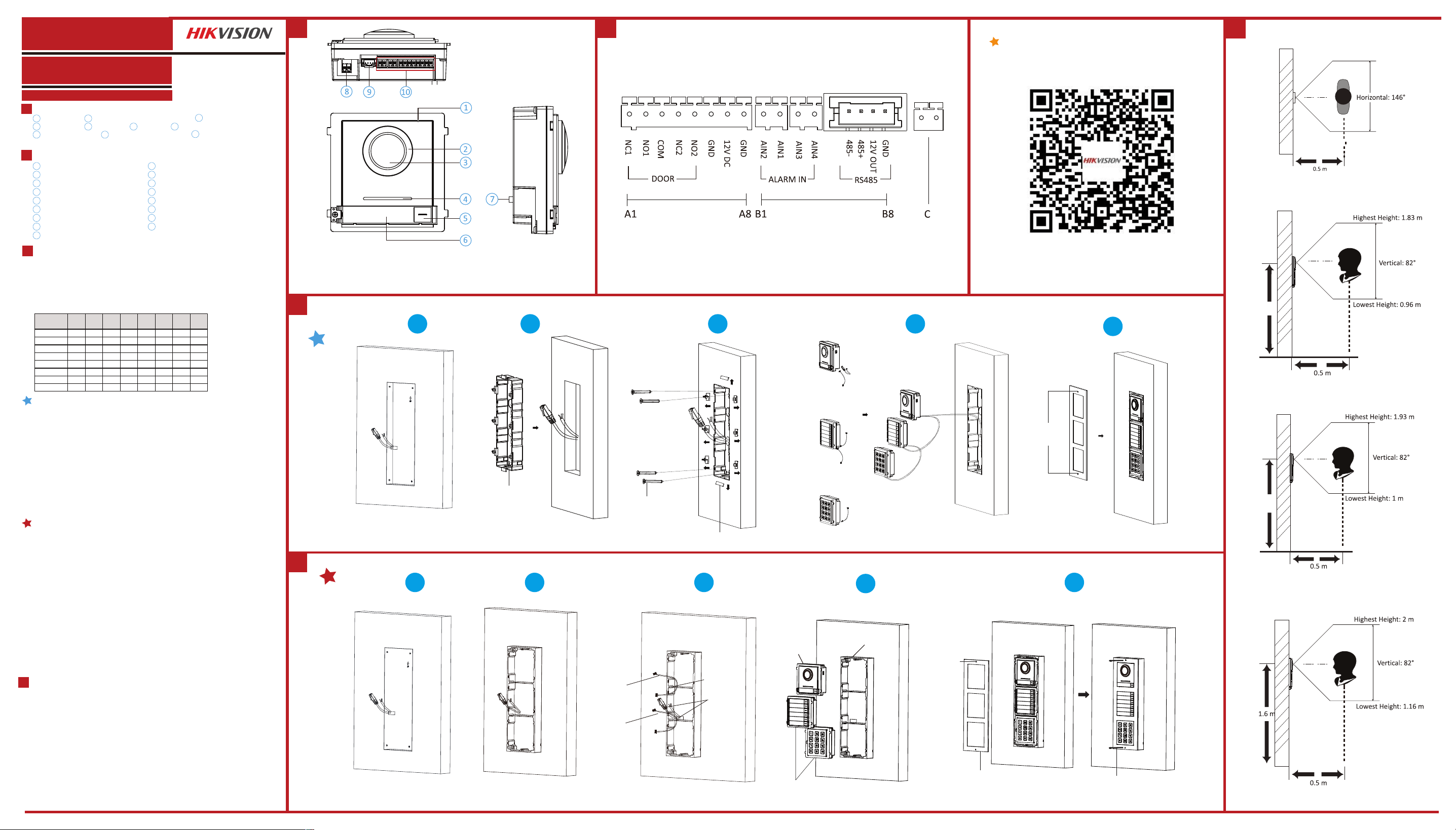
Appearance
Installation
Before you begin:
Three-Module Flush Mounting
1. Cave the installation hole, and pull the cable out.
Note: The suggested dimension of the installation hole is 321.8(W) × 108(H) × 45.5(D) mm. The suggested length of the
cables left outside is 270 mm.
2. Select a cable entry and remove the plastic sheet. Route the cables through the gang box hole. Insert the
gang box into the installation hole. Mark the gang box screw holes’ position with a marker, and take out the
gang box.
3. Drill 4 holes according to the marks on the wall, and insert the expansion sleeves into the screw holes.
Fix the gang box with 4 expansion bolts.Fill the gap between the gang box and wall with concrete or Silicone
sealant. Remove the mounting ears
with tool after concrete is dry.
4. Connect cables and insert the modules.
a.Connect Cable 1 and one end of Cable 2 to the corresponding interfaces of the main unit, then insert the
main unit into the upper grid.
b.Connect the other end of Cable 2 to the input interface of Sub Module 1. Connect one end of Sub Module
1 and insert it into the middle grid.
c.Connect the other end of Cable 3 to the input interface of Sub Module 2. Insert it into the bottom grid.
5. Fix the cover and the main unit with 2 socket head cap screws by using a hexagon wrench.
3
Terminal
2
Microphone
Low Illumination IR Supplement Light
Built-in Camera
1 2
3
4
8
A1
A2
A3
A4
A5
A6
10
5 6
9
7
Three- Module Surface Moun�ng
1. Paste the installa�on s�cker 1 onto the wall. Make sure the s�cker is placed
horizontally via measuring with the gradienter. Drill 4 holes according to the screw holes
on the s�cker.
Note: The suggested size of hole is 6(diameter) × 25(depth) mm. The suggested length of the cables le�
outside is 270 mm.
2. Remove the s�cker and insert the expansion sleeves into the screw holes. Fix the
moun�ng frame onto the wall with 4 expansion bolts.
3. Thread the module-connec�ng line across the thread holes of the frame. Pass the
main unit connec�ng line across the thread hole to the top grid and connect the cables.
a.Connect the lines and module-connec�ng line 1 to the corresponding interfaces of
the main unit, then place the main unit into the upper grid.
b.Connect the other end of the module-connec�ng line 1 to the input interface of the
sub modules via module-connec�ng line 2.
c.Organize the cables with cable �e in the package.
4. Insert the modules into the frame a�er wiring. The main unit must be placed in the
top grid.
5. Use the hexagon wrench in the package to x the cover onto the frame.
1. Tools that you need to prepare for installation: Drill (6), cross screw driver (PH1*150 mm), and gradienter.
2. Make sure all the related equipment is power-o during the installation.
3. Make sure you have congured the sub module address before installation. Valid sub module address range is
1 to 8. The No. should be unique for sub modules that connected to the same main unit. The sub module
address and corresponding switch status is shown as the gure.
Nametag
Terminals
Loudspeaker
Call Button
Two-Wire Interface
NC1: Door Lock Relay Output (NC)
NO1: Door Lock Relay Output (NO)
COM: Common Interface
GND: Grounding
NC2: Door Lock Relay Output (NC)
NO2: Door Lock Relay Output (NO)
A7
12 VDC: Power Output
A8
GND: Grounding
C
Two-Wire Interface
B7
B8
B1
B2
B3
B4
B5
B6
AIN2: For the access of Door Contact 2
AIN1: For the access of Door Contact 1
AIN3: For the access of Exit Button 1
AIN4: For the access of Exit Button 2
485-: Module-connecting Interface
485+: Module-connecting Interface
12V OUT: Module-connecting Interface
GND: Module-connecting Interface
Module-connecting Interface
TAMPER
Note: The module-connecting interface is used to connect other function module, such as nametag module, keypad
module, card reader module, etc. All these modules are known as sub module.
Note: Video intercom module door sta�on support one-module installa�on, two-module installa�on, three-
module installa�on and more-than-three-module installa�on. Here takes three-module installa�on as an example.
Sub Module
Address DIP 1 DIP 2 DIP 3 DIP 4 DIP 5 DIP 6 DIP 7 DIP 8
Module 1 ON OFF OFF OFF OFF OFF OFF OFF
Module 2 OFF ON OFF OFF OFF OFF OFF OFF
Module 3 ON ON OFF OFF OFF OFF OFF OFF
Module 4 OFF OFF ON OFF OFF OFF OFF OFF
Module 5 ON OFF ON OFF OFF OFF OFF OFF
Module 6 OFF ON ON OFF OFF OFF OFF OFF
Module 7 ON ON ON OFF OFF OFF OFF OFF
Module 8 OFF OFF OFF ON OFF OFF OFF OFF
Installation Positions
4
Recommended Installation Height (The distance between the camera and the ground): 1.4 m to 1.6 m
The FOV of the camera is : Horizontal: 146°, Vertical: 82°.
The highest visual height and lowest visual height of the camera is shown as picture.
Note: The power source should be qualified and meet limited power
source or PS2 requirements according to IEC 60950-1 or IEC 62368-1 standard.
1 2 2
3
1 3
\
Diagram References
Diagram References
E N G L I S H
Appearance
1
Installation
Before you begin:
3
Wiring
2
Make sure the device in the package is in good condition.
Make sure all the related equipment is power-off during the installation.
Check the product specification for the installation environment.
Wire the devices with power supply cables.
Door station should be connected to CH4 of the video/audio distributor with two-wire cables.
Indoor Station should be connected to any terminal of CH1 to CH3 of the video/audio distributor with two-
wire cables.
Caution: Make sure all the related equipment is power-off during the installation.
Note: The power output of CH1 to CH3: 12 VDC, Max. 4W. The power output of CH4: 24 VDC, Max. 8W.
1. Fix the DIN rail onto the wall.
Note: You are required to utilize a matched DIN rail.
2. Press the red clip upward, and lock it to the DIN rail.
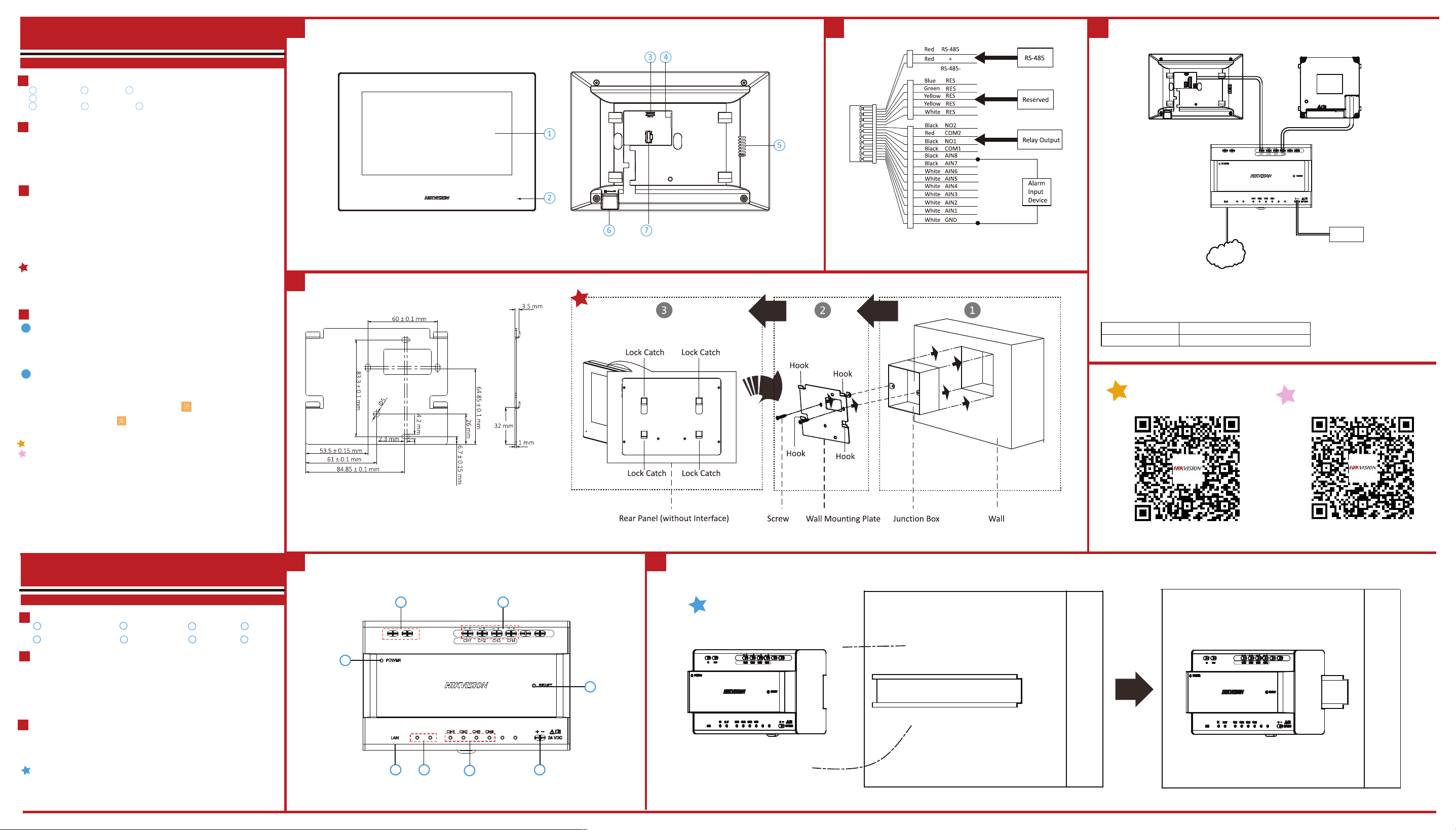
DS-KAD704Y
Video Intercom Two-Wire Video/Audio Distributor
DS-KH6320Y-WTE2
Video Intercom Two-Wire Indoor Station
Power Indicator
Cascade Interface
1 2
3 4
5 6 7 8Network Indicator
Terminals LAN
Cascade Network Indicator
Power Input Reset
Note:
The power adapter is contained only in the DS-KIS702Y-P Kit.
NetworkNetwork
Door Station
Video/Audio Distributor
Indoor Station
IN
OUT
MAX
4W
24VDC
MAX
8W
IN
OUT
24 VDC
Power Input
Model Manufacturer
KPL-060M-II Channel Well Technology Co., Ltd
The detail for the power adapter contained in the package is as follows:
2 3
7
8
6
4 5
1
IN
OUT
MAX
4W
24VDC
MAX
8W
IN
OUT
24VDC
MAX
4W
MAX
8W
24VDC
MAX
4W
MAX
8W
1
Appearance
Installation
Before you begin:
Wall Mounting with Junction Box
3
Getting Started
4
Wiring
2
Display Screen
Microphone
Debugging Port
1 2 3
4
5 6 7
1. Tools that you need to prepare for installation: Make sure the device in the package is in good condition
and all the assembly parts are included.
2. The power supply the indoor station supports is 24 VDC. Please make sure your power supply matches
your indoor station.
3. Make sure all the related equipment is power-o during the installation.
4. Check the product specication for the installation environment.
1. Chisel a hole in the wall. The size of the hole should be 76 mm (width) × 76 mm (length) × 50 mm (depth).
2. Insert the junction box to the hole chiseled on the wall.
3. Fix the wall mounting plate to the junction box with 2 screws.
4. Hook the indoor station to the wall mounting plate tightly by inserting the plate hooks into the slots on the
rear panel of the indoor station, during which the lock catch will be locked automatically.
TF Card Slot
Loudspeaker
Two-Wire Interface
Alarm Terminal
Note: The debugging port is used for debugging only.
There are 20 pins in the terminal on the rear panel of the indoor station: 2 RS-485 pins, 5 reserved pins, 4
relay output pins, 8 alarm input pins, and 1 GND pin.
The wall mounting plate and the junction box are required to install the indoor station onto the wall.
The dimension of junction box should be 75 mm (width) × 75 mm (length) × 50 mm (depth).
The dimension of wall mounting plate is shown.
Wire the devices with power supply cables.
Caution: Make sure all the related equipment is power-o during the installation.
Note: The power output of the indoor station is 24 VDC, 4 W.
Refer to Video Intercom Indoor Station Conguration Guide (scan the QR code) for details.
Refer to Video Intercom Indoor Station Operation Guide (scan the QR code) for details.
Quick Configuration
2
1. Power on the device. It will enter the activation page automatically.
2. Create a password and confirm it.
3. Tap OK to activate the indoor station.
You are required to activate the device first by setting a strong password for it before
you can use the device.
1
Activate Indoor Station
• After Activation, you can follow the wizard to complete quick configuration, including language
settings, network settings, indoor station settings, linked devices settings, etc.
• If you want to enter the wizard page, you can tap Settings → → Configuration, and enter the
admin (activation) password. Tap to enter the system maintenance page.