
Two-Wire Video Intercom Bundle·Quick Start Guide
1
Quick Start Guide
Two-Wire Video Intercom Bundle
Quick Start Guide
0100001080117

Two-Wire Video Intercom Bundle·Quick Start Guide
i
© 2018 Hangzhou Hikvision Digital Technology Co., Ltd.
About this Manual
This Manual is subject to domestic and international copyright protection. Hangzhou
Hikvision Digital Technology Co., Ltd. (“Hikvision”) reserves all rights to this manual. This
manual cannot be reproduced, changed, translated, or distributed, partially or wholly, by
any means, without the prior written permission of Hikvision.
Please use this user manual under the guidance of professionals.
Trademarks
and other Hikvision marks are the property of Hikvision and are
registered trademarks or the subject of applications for the same by Hikvision and/or its
affiliates. Other trademarks mentioned in this manual are the properties of their
respective owners. No right of license is given to use such trademarks without express
permission.
Disclaimer
TO THE MAXIMUM EXTENT PERMITTED BY APPLICABLE LAW, HIKVISION MAKES NO WARRANTIES,
EXPRESS OR IMPLIED, INCLUDING WITHOUT LIMITATION THE IMPLIED WARRANTIES OF
MERCHANTABILITY AND FITNESS FOR A PARTICULAR PURPOSE, REGARDING THIS MANUAL.
HIKVISION DOES NOT WARRANT, GUARANTEE, OR MAKE ANY REPRESENTATIONS REGARDING THE
USE OF THE MANUAL, OR THE CORRECTNESS, ACCURACY, OR RELIABILITY OF INFORMATION
CONTAINED HEREIN. YOUR USE OF THIS MANUAL AND ANY RELIANCE ON THIS MANUAL SHALL BE
WHOLLY AT YOUR OWN RISK AND RESPONSIBILITY.
TO THE MAXIMUM EXTENT PERMITTED BY APPLICABLE LAW, IN NO EVENT WILL HIKVISION, ITS
DIRECTORS, OFFICERS, EMPLOYEES, OR AGENTS BE LIABLE TO YOU FOR ANY SPECIAL,
CONSEQUENTIAL, INCIDENTAL, OR INDIRECT DAMAGES, INCLUDING, AMONG OTHERS, DAMAGES
FOR LOSS OF BUSINESS PROFITS, BUSINESS INTERRUPTION, SECURITY BREACHES, OR LOSS OF DATA
OR DOCUMENTATION, IN CONNECTION WITH THE USE OF OR RELIANCE ON THIS MANUAL, EVEN IF
HIKVISION HAS BEEN ADVISED OF THE POSSIBILITY OF SUCH DAMAGES.
SOME JURISDICTIONS DO NOT ALLOW THE EXCLUSION OR LIMITATION OF LIABILITY OR CERTAIN
DAMAGES, SO SOME OR ALL OF THE ABOVE EXCLUSIONS OR LIMITATIONS MAY NOT APPLY TO YOU.
Support
Should you have any questions, please do not hesitate to contact your local dealer.
Two-Wire Video Intercom Bundle·Quick Start Guide
ii
Regulatory Information
FCC Information
Please take attention that changes or modification not expressly approved by the party
responsible for compliance could void the user’s authority to operate the equipment.
FCC compliance: This equipment has been tested and found to comply with the limits
for a Class A digital device, pursuant to part 15 of the FCC Rules. These limits are
designed to provide reasonable protection against harmful interference when the
equipment is operated in a commercial environment. This equipment generates, uses,
and can radiate radio frequency energy and, if not installed and used in accordance with
the instruction manual, may cause harmful interference to radio communications.
Operation of this equipment in a residential area is likely to cause harmful interference
in which case the user will be required to correct the interference at his own expense.
FCC Conditions
This device complies with part 15 of the FCC Rules. Operation is subject to the following
two conditions:
1. This device may not cause harmful interference.
2. This device must accept any interference received, including interference that may
cause undesired operation.
EU Conformity Statement
This product and - if applicable - the supplied accessories too are
marked with "CE" and comply therefore with the applicable harmonized
European standards listed under the EMC Directive 2014/30/EU, the
RoHS Directive 2011/65/EU.
2012/19/EU (WEEE directive): Products marked with this symbol cannot
be disposed of as unsorted municipal waste in the European Union. For
proper recycling, return this product to your local supplier upon the
purchase of equivalent new equipment, or dispose of it at designated
collection points. For more information see: www.recyclethis.info
2006/66/EC (battery directive): This product contains a battery that
cannot be disposed of as unsorted municipal waste in the European
Union. See the product documentation for specific battery information.
The battery is marked with this symbol, which may include lettering to
indicate cadmium (Cd), lead (Pb), or mercury (Hg). For proper recycling,
return the battery to your supplier or to a designated collection point.
For more information see: www.recyclethis.info
Industry Canada ICES-003 Compliance
This device meets the CAN ICES-3 (A)/NMB-3(A) standards requirements.
This device complies with Industry Canada licence-exempt RSS standard(s). Operation is
subject to the following two conditions:
(1) this device may not cause interference, and

Two-Wire Video Intercom Bundle·Quick Start Guide
iii
(2) this device must accept any interference, including interference that may cause
undesired operation of the device.
Le présent appareil est conforme aux CNR d'Industrie Canada applicables aux appareils
radioexempts de licence. L'exploitation est autorisée aux deux conditions suivantes :
(1) l'appareil ne doit pas produire de brouillage, et
(2) l'utilisateur de l'appareil doit accepter tout brouillage radioélectrique subi, même si
le brouillage est susceptible d'en compromettre le fonctionnement.
Under Industry Canada regulations, this radio transmitter may only operate using an
antenna of a type and maximum (or lesser) gain approved for the transmitter by
Industry Canada. To reduce potential radio interference to other users, the antenna type
and its gain should be so chosen that the equivalent isotropically radiated power (e.i.r.p.)
is not more than that necessary for successful communication.
Conformément à la réglementation d'Industrie Canada, le présent émetteur radio peut
fonctionner avec une antenne d'un type et d'un gain maximal (ou inférieur) approuvé
pour l'émetteur par Industrie Canada. Dans le but de réduire les risques de brouillage
radioélectrique à l'intention des autres utilisateurs, il faut choisir le type d'antenne et
son gain de sorte que la puissance isotrope rayonnée équivalente (p.i.r.e.) ne dépasse
pas l'intensité nécessaire à l'établissement d'une communication satisfaisante.
This equipment should be installed and operated with a minimum distance 20cm
between the radiator and your body.
Cet équipement doit être installé et utilisé à une distance minimale de 20 cm entre le
radiateur et votre corps.
Available Models
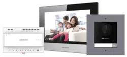
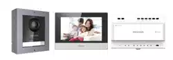
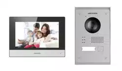
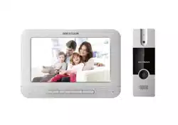
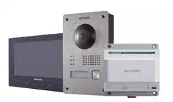
This manual is applicable to the two-wire video intercom bundle.
This bundle includes 1 indoor station (DS-KH8340-TCE2), 1 villa door station
(DS-KV8103-IME2) and 1 video/audio distributor (DS-KAD709).
Symbol Conventions
The symbols that may be found in this document are defined as follows.
Symbol
Description
Indicates a hazardous situation which, if not avoided, will or
could result in death or serious injury.
Indicates a potentially hazardous situation which, if not
avoided, could result in equipment damage, data loss,
performance degradation, or unexpected results.
Provides additional information to emphasize or supplement
important points of the main text.
Safety Instruction

Two-Wire Video Intercom Bundle·Quick Start Guide
iv
The working temperature of the indoor station is from -10 °C to 55 °C.
The working temperature of the door station is from -30 °C to 60 °C.
The working temperature of the video/audio distributor is from -10 °C to 55 °C.
All the electronic operation should be strictly compliance with the electrical safety
regulations, fire prevention regulations and other related regulations in your local
region.
Please use the power adapter, which is provided by normal company. The power
consumption cannot be less than the required value.
Do not connect several devices to one power adapter as adapter overload may
cause over-heat or fire hazard.
Please make sure that the power has been disconnected before you wire, install or
dismantle the device.
When the product is installed on wall, the device shall be firmly fixed.
If smoke, odors or noise rise from the device, turn off the power at once and
unplug the power cable, and then please contact the service center.
If the product does not work properly, please contact your dealer or the nearest
service center. Never attempt to disassemble the device yourself. (We shall not
assume any responsibility for problems caused by unauthorized repair or
maintenance.)
Do not drop the device or subject it to physical shock, and do not expose it to high
electromagnetism radiation. Avoid the equipment installation on vibrations
surface or places subject to shock (ignorance can cause equipment damage).
Do not place the device in extremely hot (refer to the specification of the device
for the detailed operating temperature), cold, dusty or damp locations, and do not
expose it to high electromagnetic radiation.
The device cover hall be kept from rain and moisture.
Exposing the equipment to direct sun light, low ventilation or heat source such as
heater or radiator is forbidden (ignorance can cause fire danger).
Do not aim the device at the sun or extra bright places. A blooming or smear may
occur otherwise (which is not a malfunction however), and affecting the
endurance of sensor at the same time.
Please use the provided glove when open up the device cover, avoid direct contact
with the device cover, because the acidic sweat of the fingers may erode the
surface coating of the device cover.
Please use a soft and dry cloth when clean inside and outside surfaces of the
device cover, do not use alkaline detergents.
Please keep all wrappers after unpack them for future use. In case of any failure
occurred, you need to return the device to the factory with the original wrapper.

Two-Wire Video Intercom Bundle·Quick Start Guide
v
Transportation without the original wrapper may result in damage on the device
and lead to additional costs.
The power supply must conform to LPS. The recommended adaptor models and
manufacturers are shown as below. Use the attached adapter, and do not change
the adaptor randomly.
Model
Manufacturer
KPL-060M-II
Channel Well Technology Co., Ltd.

Two-Wire Video Intercom Bundle·Quick Start Guide
vi
Table of Contents
1 Appearance Description ............................................................................... 1
1.1 Indoor Station .......................................................................................................... 1
1.2 Door Station............................................................................................................. 2
1.3 Video/Audio Distributor .......................................................................................... 2
2 Terminal and Wiring ..................................................................................... 4
2.1 Terminals and Interfaces .......................................................................................... 4
2.1.1 Indoor Station Terminals ................................................................................... 4
2.1.2 Door Station Terminals ...................................................................................... 5
2.1.3 Video/audio distributor Terminals and Interfaces ............................................ 6
2.2 Wiring ...................................................................................................................... 6
3 Installation ................................................................................................... 9
3.1 Indoor Station Installation ....................................................................................... 9
3.2 Door Station Installation ........................................................................................ 10
3.3 Video/Audio Distributor Installation ..................................................................... 12
4 Getting Started ........................................................................................... 15
4.1 Activate Device via Batch Configuration Tool......................................................... 15
4.2 Editing Network Parameters .................................................................................. 16
4.3 Adding Device .........................................................................................................17
4.3.1 Adding Online Devices ......................................................................................17
4.3.2 Adding by IP Address ....................................................................................... 18
4.4 Set Indoor Station .................................................................................................. 19
4.4.1 Set Room No. .................................................................................................. 19
4.4.2 Set Linked Network Parameters ...................................................................... 20
4.5 Add Device to App ................................................................................................. 20
4.5.1 Set up the App................................................................................................. 20
4.5.2 Add Device ...................................................................................................... 21
5 Video Intercom Operation .......................................................................... 24
Appendix ...................................................................................................... 25
Installation Notice ....................................................................................................... 25
Two-Wire Video Intercom Bundle·Quick Start Guide
1
1 Appearance Description
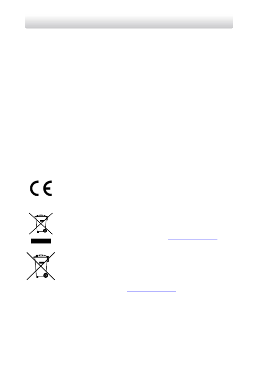
1.1 Indoor Station
Figure 1-1 Front Panel
Table 1-1 Components Description
No.
Description
1
Power Supply Indicator
2
Information Indicator
3
Alarm Indicator
4
Call Accept/Decline Key
5
Unlock Key
6
Live View Key
7
Management Center Key
8
LCD Display Screen
9
Microphone
Figure 1-2 Rear Panel
Table 1-2 Components Description
No.
Description
10
Two-Wire Interface
11
Terminals
12
Serial Port
13
TF Card Slot
14
Loudspeaker
Two-Wire Video Intercom Bundle·Quick Start Guide
2
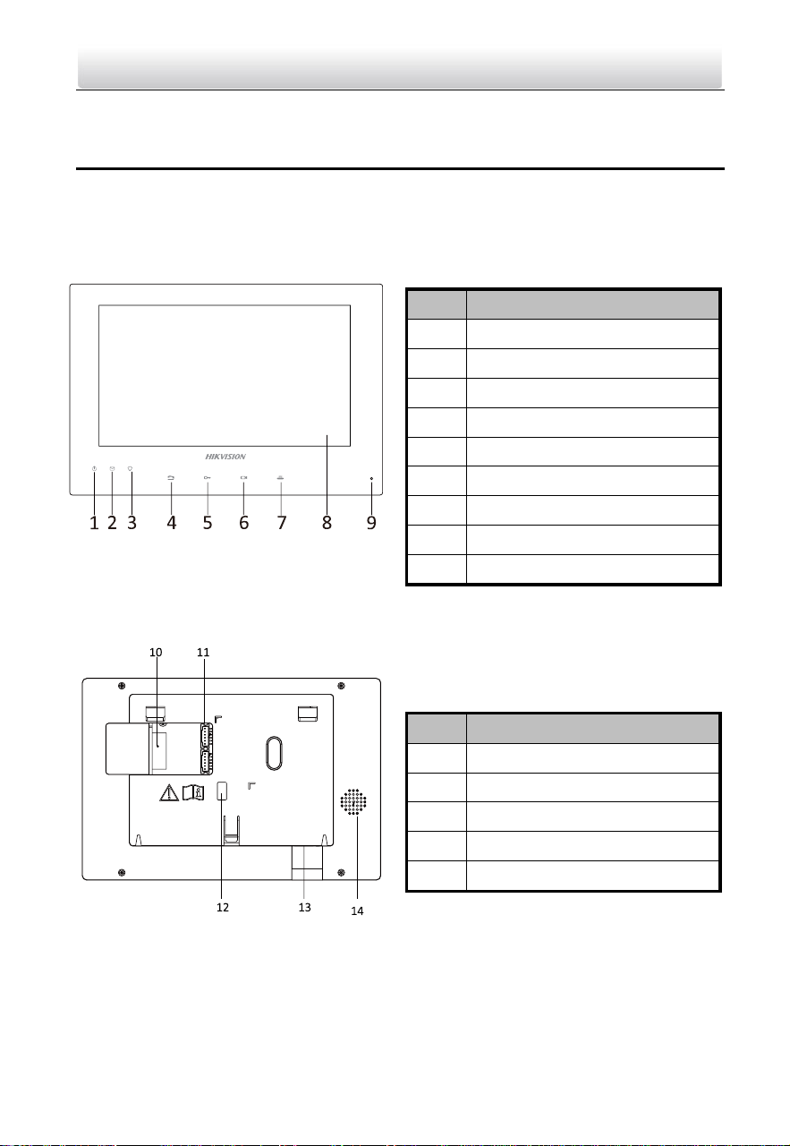
1.2 Door Station
Figure 1-3 Door Station Appearance
Table 1-3 Components Description
No.
Description
1
Microphone
2
Calling Indicator
3
Speaking Indicator
4
Open Door Indicator
5
Built-in Camera
6
Supplement Light
7
Loudspeaker
8
Call Button
9
Tamper Button
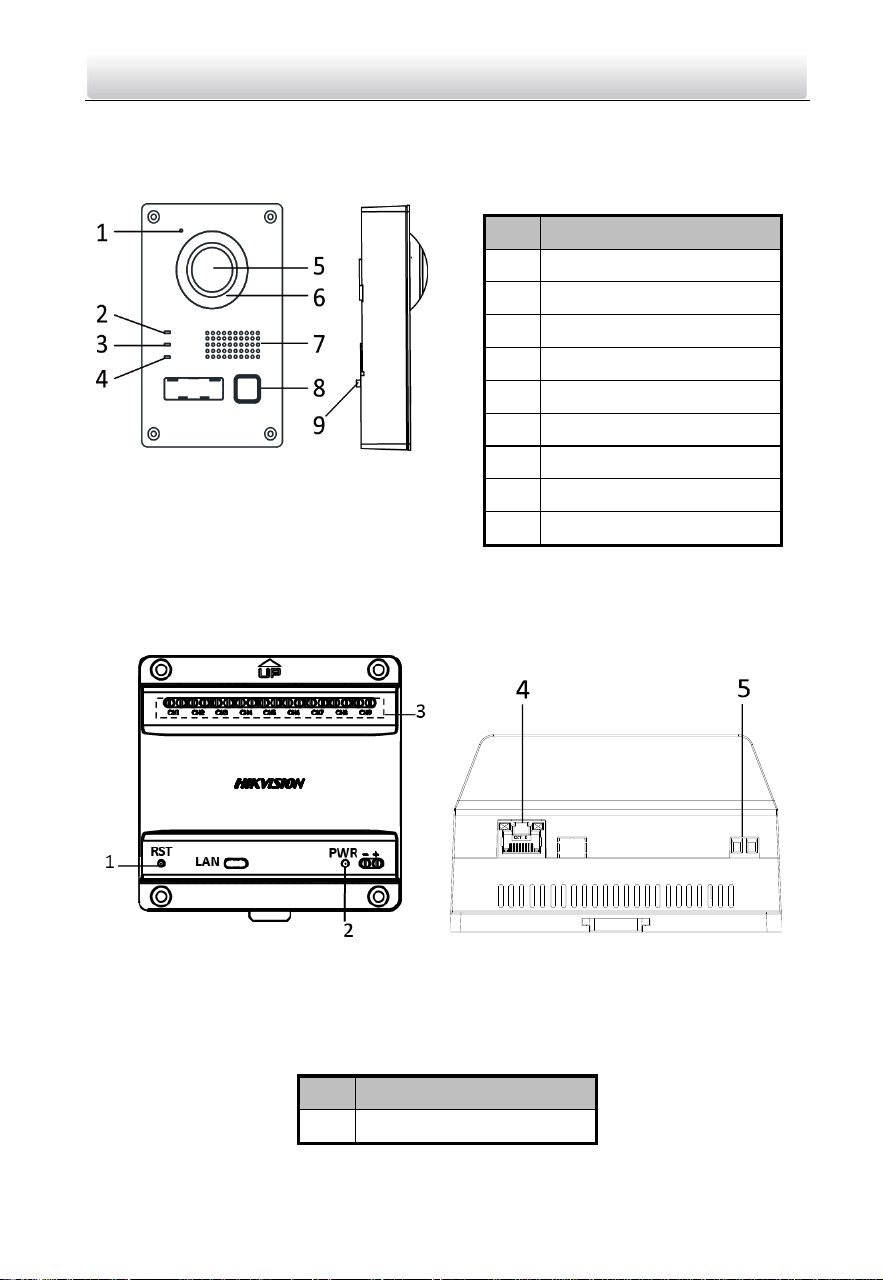
1.3 Video/Audio Distributor
Figure 1-4 Video/Audio Distributor Appearance
Table 1-4 Components Description
No.
Description
1
Reset Button

Two-Wire Video Intercom Bundle·Quick Start Guide
3
2
Power Indicator
3
Two-Wire Interface
4
RJ-45 Interface
5
Power Supply Interface
Two-Wire Video Intercom Bundle·Quick Start Guide
4
2 Terminal and Wiring
2.1 Terminals and Interfaces
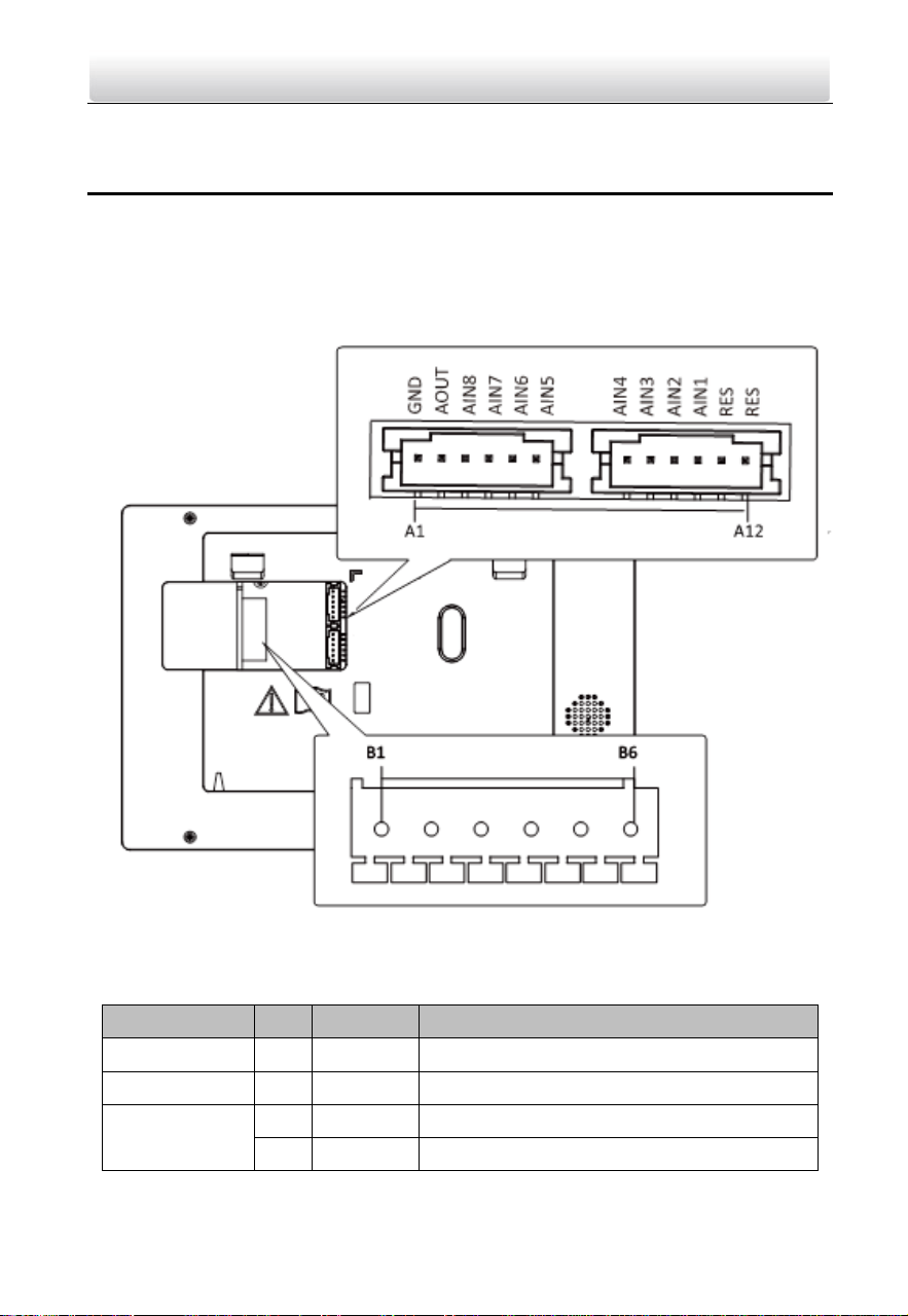
2.1.1 Indoor Station Terminals
Figure 2-1 Indoor Station Terminals
Table 2-1 Descriptions of Terminals and Interfaces
Name
No.
Interface
Description
Grounding
A1
GND
Grounding
ALARM OUT
A2
AOUT
Alarm Relay Out
ALARM IN
A3
AIN8
Zone Detector Input Terminal 8
A4
AIN7
Zone Detector Input Terminal 7
Two-Wire Video Intercom Bundle·Quick Start Guide
5
Name
No.
Interface
Description
A5
AIN6
Zone Detector Input Terminal 6
A6
AIN5
Zone Detector Input Terminal 5
A7
AIN4
Zone Detector Input Terminal 4
A8
AIN3
Zone Detector Input Terminal 3
A9
AIN2
Zone Detector Input Terminal 2
A10
AIN1
Zone Detector Input Terminal 1
RES
A11
RES
Reserved
A12
RES
Reserved
Power Supply
and Network
Transmission
B1
Two-Wire
Interface
3 groups of two-wire interfaces (B1 and B2,
B3 and B4, B5 and B6) for power supply and
network transmission of the indoor station
B2
B3
B4
B5
B6
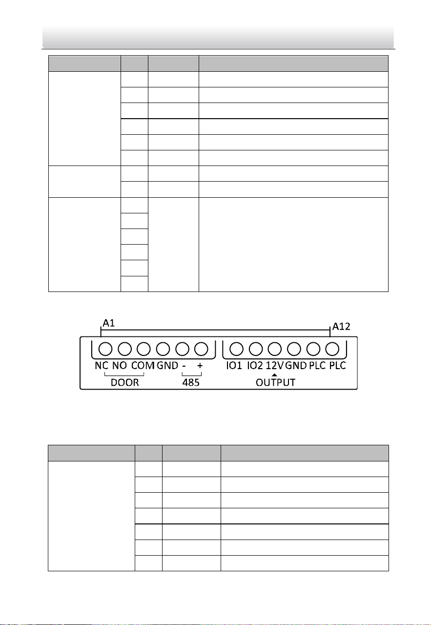
2.1.2 Door Station Terminals
Figure 2-2 Door Station Terminals
Table 2-2 Descriptions of Terminals and Interfaces
Name
No.
Interface
Description
Terminals
A1
NC
Normally Close
A2
NO
Normally Open
A3
COM
COM Port
A4
GND
Grounding
A5
485-
Reserved
A6
485+
Reserved
A7
IO1
Alarm Input 1
Two-Wire Video Intercom Bundle·Quick Start Guide
6
Name
No.
Interface
Description
A8
IO2
Alarm Input 2
A9
12V
Power Supply Output
A10
GND
Grounding
A11
PLC
Power Input
A12
PLC
Power Output
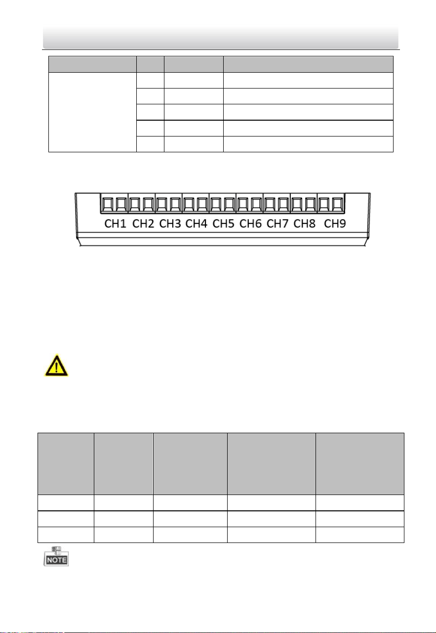
2.1.3 Video/audio distributor Terminals and Interfaces
Figure 2-3 Video/audio distributor Terminals
The video/audio distributor contains 9 groups of two-wire interfaces for the access of
other devices.
2.2 Wiring
Cautions
Make sure all the related equipment is power-off during the installation.
Choose power cables according to the distance between the door station and the
video/audio distributor.
Cable
Resistance
per 100 m
Max.
Transmission
Distance
Max. Distance
(Door station
doesn’t supply
power for electric
lock.)
Max. Distance
(Door station
supplies power for
electric lock.)
24AWG
10 Ω
50 m
50 m
30 m
20AWG
7 Ω
100 m
100 m
80 m
18AWG
4 Ω
150 m
150 m
100 m
Two-Wire Video Intercom Bundle·Quick Start Guide
7
The input voltage for electric lock is 12 V and the maximum current is 200 mA.
When use the wire in network cable as the 24AWG cable, use two wires connect to
one device and spare the other six.
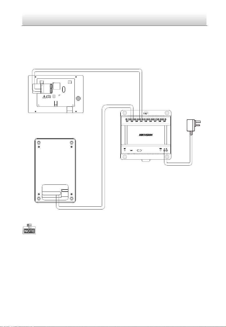
Wire the three devices with power supply cables as the picture shown below.
Indoor Station
Door Station
Video/Audio
Distributor
Power Adapter
Figure 2-4 Wiring
It’s suggested to connect only one video/audio distributor to one switch. If you need
to connect more than one video/audio distributor to the switch, please set the PLC
channel.
It’s suggested to set the PLC channel when there are two or more sets of bundles in
use and the distance between the wires of two bundles are less than 1 m. The PLC
channel function is made to avoid crosstalk between channels.
The steps as follow:
Steps:
1. Press call button on the door station for 20 seconds to enable PLC setting mode.

Two-Wire Video Intercom Bundle·Quick Start Guide
8
The door station plays 8 rings on a continuous loop.
2. Press the button during the ring you selected.
The door station prompts “Setting succeeded.” after 1 to 2 mins.
3. Check the PLC setting on the indoor station.
Two-Wire Video Intercom Bundle·Quick Start Guide
9
3 Installation
3.1 Indoor Station Installation
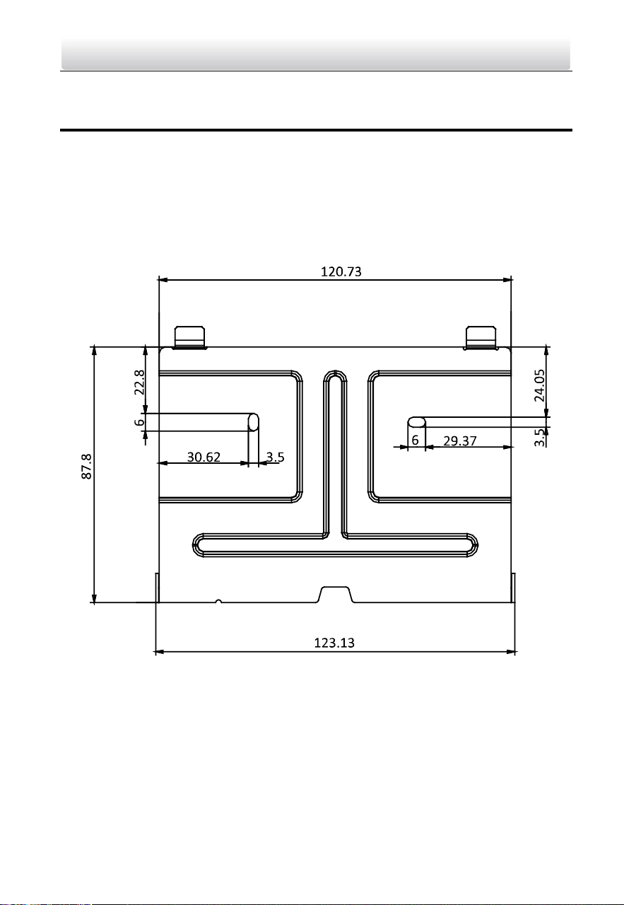
Installation Accessory Description
The wall mounting plate is required to install the indoor station onto the wall.
The dimension of wall mounting plate is shown in below.
Figure 3-1 Wall Mounting Plate
Mount Indoor Station
Before you start:
Make sure the device in the package is in good condition.
Make sure all the related equipment is power-off during the installation.
Connect cables to the indoor station before mounting.
Steps:
Two-Wire Video Intercom Bundle·Quick Start Guide
10
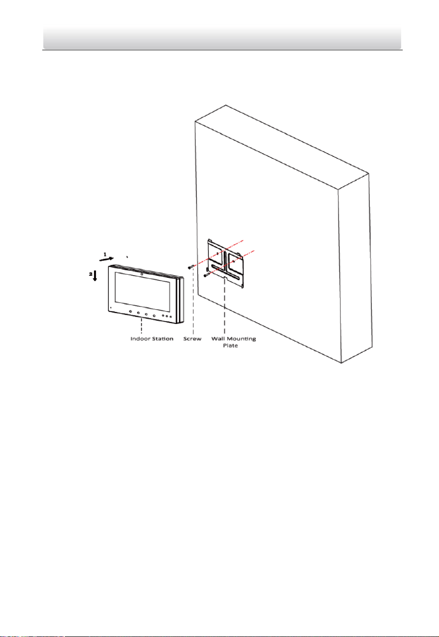
1. Fix the wall mounting plate to the wall with 2 screws.
2. Hook the indoor station to the wall mounting plate tightly by inserting the plate hooks
into the slots on the rear panel of the indoor station, during which the lock catch will
be locked automatically.
Figure 3-2 Hooking the Indoor Station to the Plate
3.2 Door Station Installation
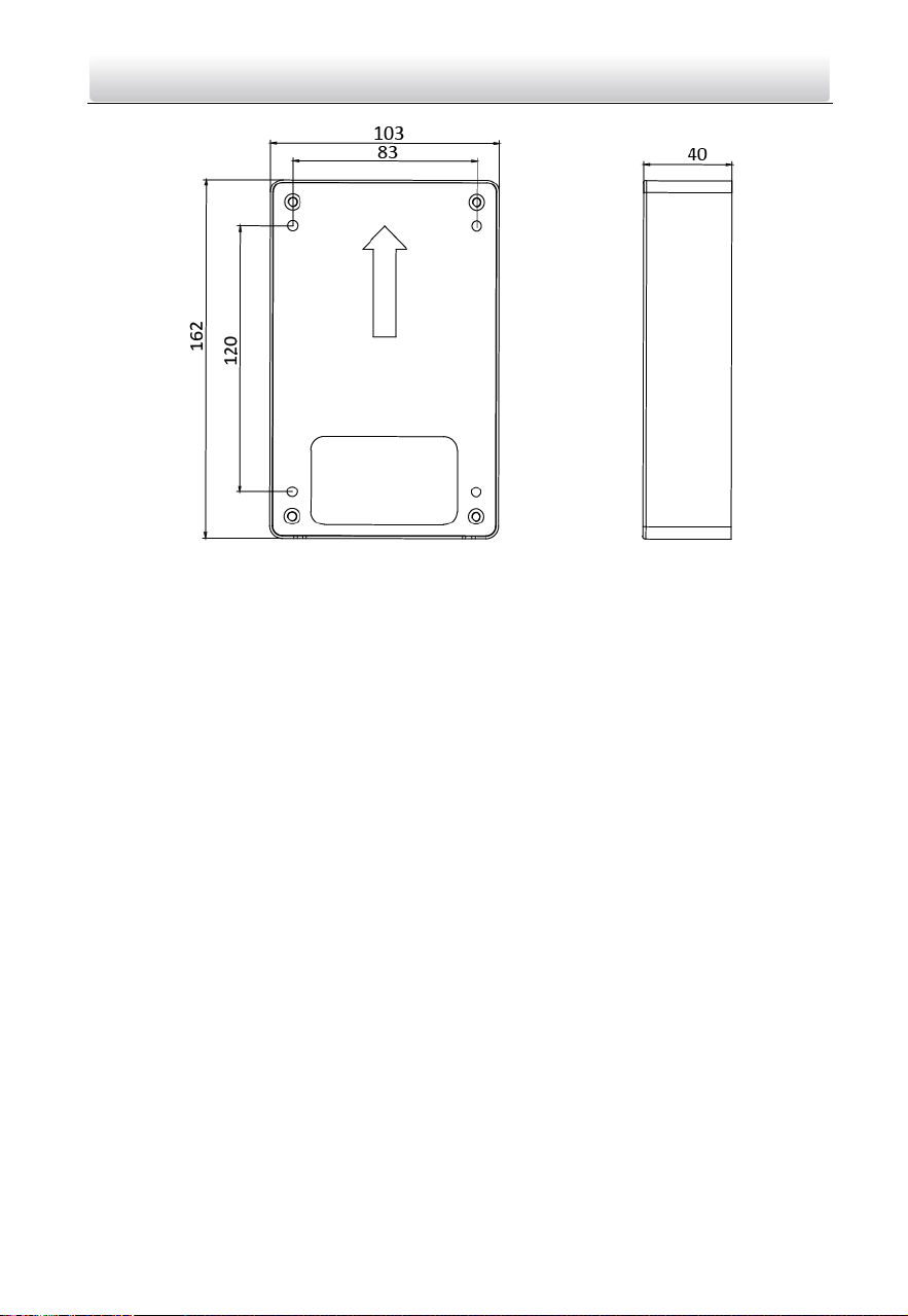
Installation Accessory Description
To install the door station onto the wall, you are required to utilize a matched gang box.
The dimension of gang box is shown in below.
Two-Wire Video Intercom Bundle·Quick Start Guide
11
Figure 3-3 Gang Box
Mount Door Station
The door stations supports surface mounting and flush mounting. Here takes surface
mounting as an example.
Before you start:
Make sure the device in the package is in good condition.
Make sure all the related equipment is power-off during the installation.
Connect cables to the door station before mounting.
Steps:
1. Take the gang box and screws from the packing box.
2. Fix the gang box onto the wall with 4 screws
3. Install the door station into the gang box, and fix it with 4 screws.

Two-Wire Video Intercom Bundle·Quick Start Guide
12
Figure 3-4 Mount the Door Station
3.3 Video/Audio Distributor Installation
You can mount the video/audio distributor with screws or DIN rail.
Before you start:
Make sure the device in the package is in good condition.
Make sure all the related equipment is power-off during the installation.
Check the product specification for the installation environment.
Mode 1
Steps:
1. Take the video/audio distributor and screws from the packing box.
2. Fix the video/audio distributor onto the wall with 4 screws, as shown in the figure
below.
Two-Wire Video Intercom Bundle·Quick Start Guide
13
Figure 3-5 Fix the Video/Audio Distributor
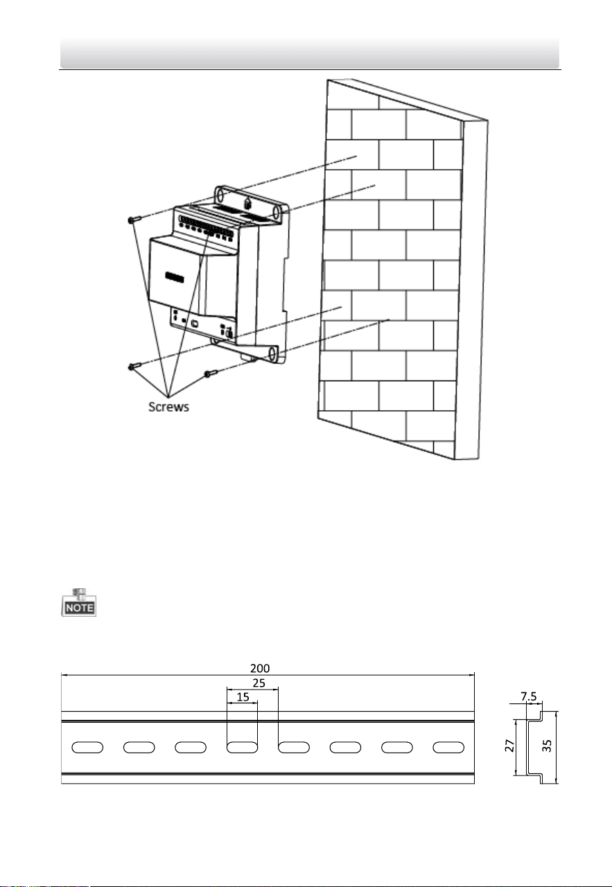
Mode 2
Steps:
1. Take the video/audio distributor from the packing box.
2. Fix the DIN rail onto the wall.
You are required to utilize a matched DIN rail.
The suggested dimension for the DIN rail as below:
Figure 3-6 DIN Rail Dimension
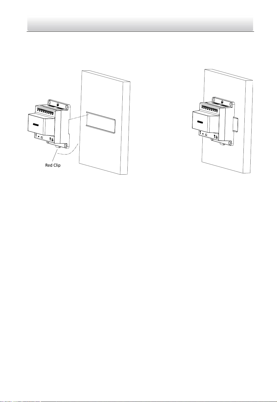
Two-Wire Video Intercom Bundle·Quick Start Guide
14
3. Press the red clip upward, and lock it to the DIN rail.
Figure 3-7 Fix the Video/Audio Distributor to DIN Rail
Two-Wire Video Intercom Bundle·Quick Start Guide
15
4 Getting Started
4.1 Activate Device via Batch Configuration Tool
Purpose:
You are required to activate the device first by setting a strong password for it before
you can use the device. The three devices can be activated in the same way.
Activation via Batch Configuration Tool, and Activation via iVMS-4200 are supported.
Here take activation via Batch Configuration Tool as example to introduce the device
activation. Please refer to the user manual for the activation via iVMS-4200.
Before you start:
Make sure the video/audio distributor is connected to the internet via network cable.
Make sure the indoor station and door station are connected to the video/audio
distributor via power cables.
Make sure all devices are power-on during the activation.
The bundle doesn’t need to work with master station, SIP server, etc.
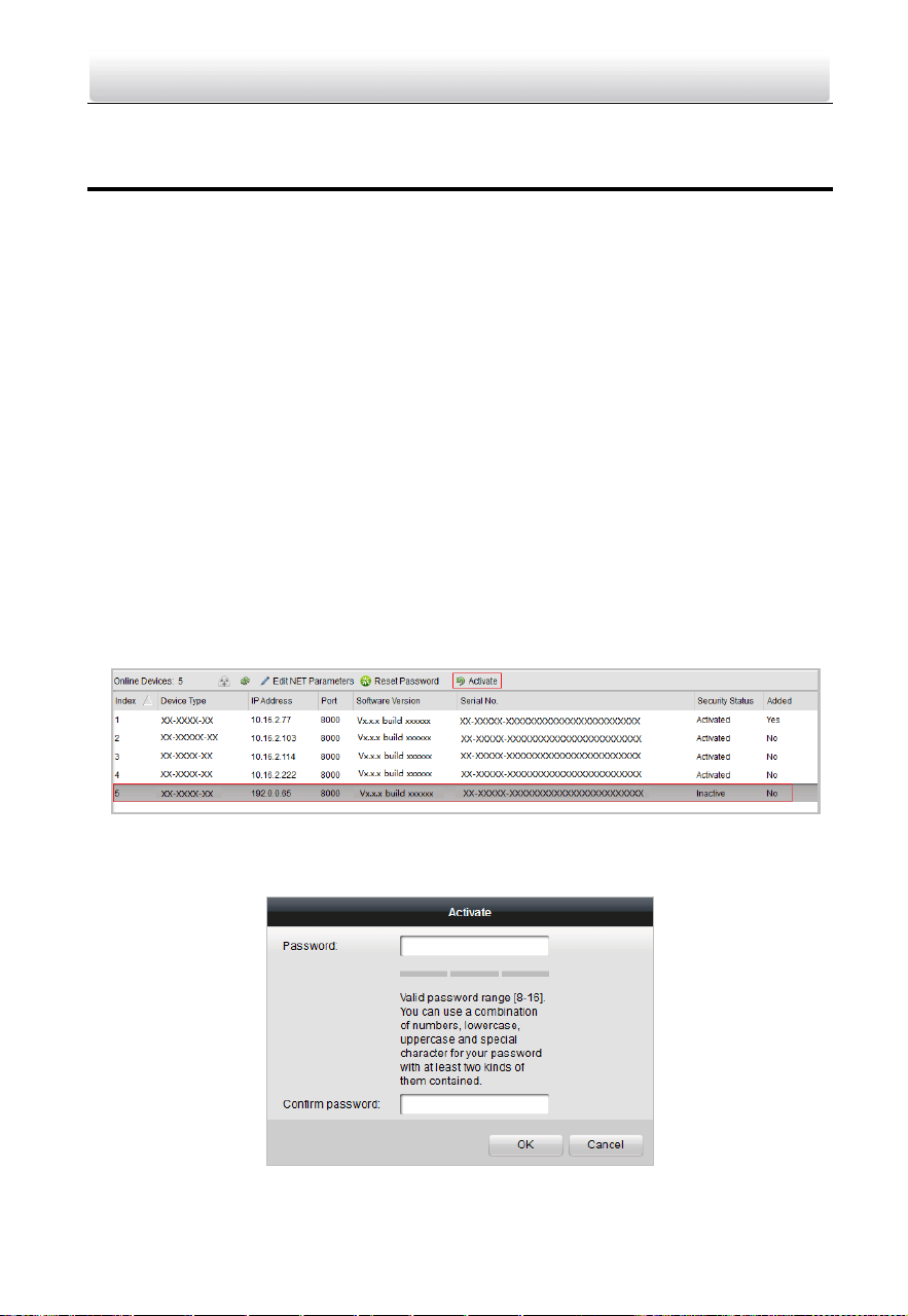
Steps:
1. Run the Batch Configuration Tool.
Figure 4-1 Select Inactive Device
2. Select an inactivated device and click the Activate button.
Figure 4-2 Activation
Two-Wire Video Intercom Bundle·Quick Start Guide
16
3. Create a password, and confirm the password.
STRONG PASSWORD RECOMMENDED– We highly recommend you create a
strong password of your own choosing (Using a minimum of 8
characters, including at least three of the following categories:
upper case letters, lower case letters, numbers, and special
characters.) in order to increase the security of your product. And we
recommend you reset your password regularly, especially in the high security
system, resetting the password monthly or weekly can better protect your
product.
4. Click the OK button to activate the device.
When the device is not activated, the basic operation and remote operation of device
cannot be performed.
You can hold the Ctrl or Shift key to select multiple devices in the online devices, and
click the Activate button to activate devices in batch.
4.2 Editing Network Parameters
Purpose:
To operate and configure the device via LAN (Local Area Network), you need connect the
device in the same subnet with you PC. You can edit network parameters via batch
configuration tool, and iVMS-4200 software. Here take editing network parameters via
batch configuration tool as example.
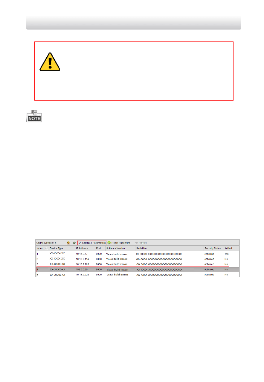
Steps:
1. Select an online activated device and click the Edit NET Parameters button.
Figure 4-3 Click Edit NET Parameters Button
2. Change the device IP address and gateway address to the same subnet with your
computer.
3. Enter the password and click the OK button to activate the network parameters
modification.
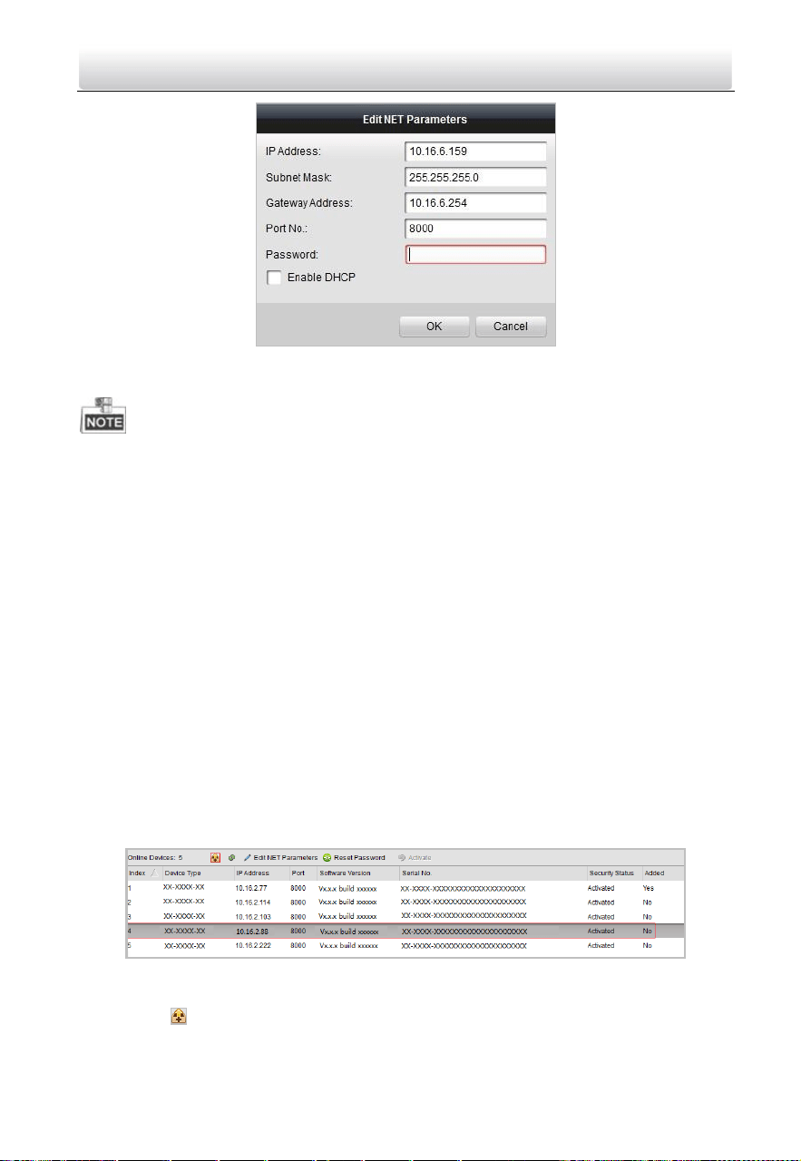
Two-Wire Video Intercom Bundle·Quick Start Guide
17
Figure 4-4 Edit Network Parameters
The default port No. is 8000.
After editing the network parameters of device, you should add the devices to the
device list again.
4.3 Adding Device
For batch configuration tool and iVMS-4200 software, you should add device to the
software so as to configure the device remotely.
3 ways for adding the device are supported: adding active online devices within your
subnet, adding device by IP address, and adding device by IP segment. Here take adding
online device and adding device by IP address via batch configuration tool as example.
4.3.1 Adding Online Devices
Steps:
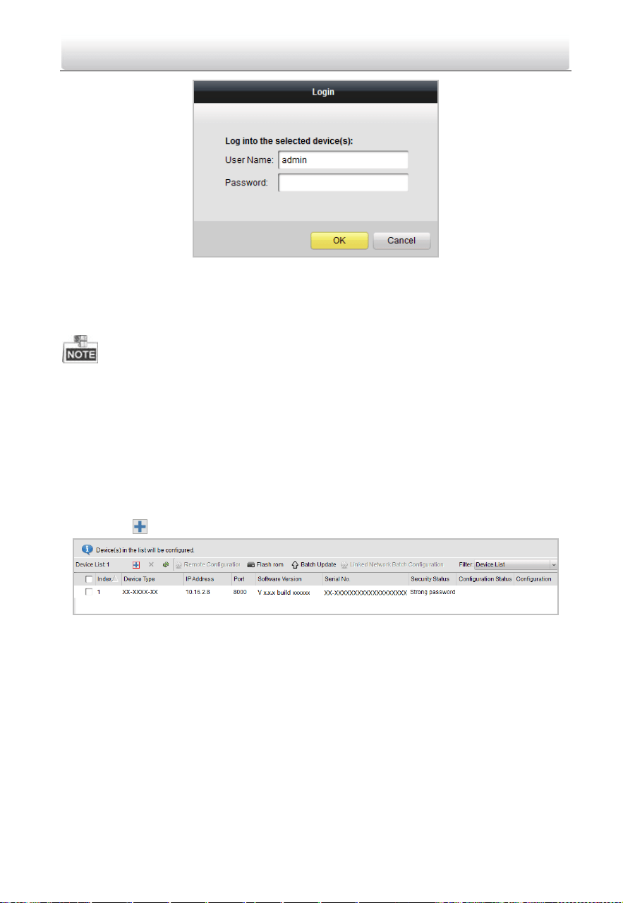
1. Select an active online device or hold the Ctrl or Shift key to select multiple devices in
the online devices list.
Figure 4-5 Online Devices Interfaces
2. Click the button to pop up the login dialog box.
Two-Wire Video Intercom Bundle·Quick Start Guide
18
Figure 4-6 Login Dialog Box
3. Enter the user name and password.
4. Click the OK button to save the settings.
Only devices successfully logged in will be added to the device list for configuration.
If you add devices in batch, please make sure selected devices have the same user
name and password.
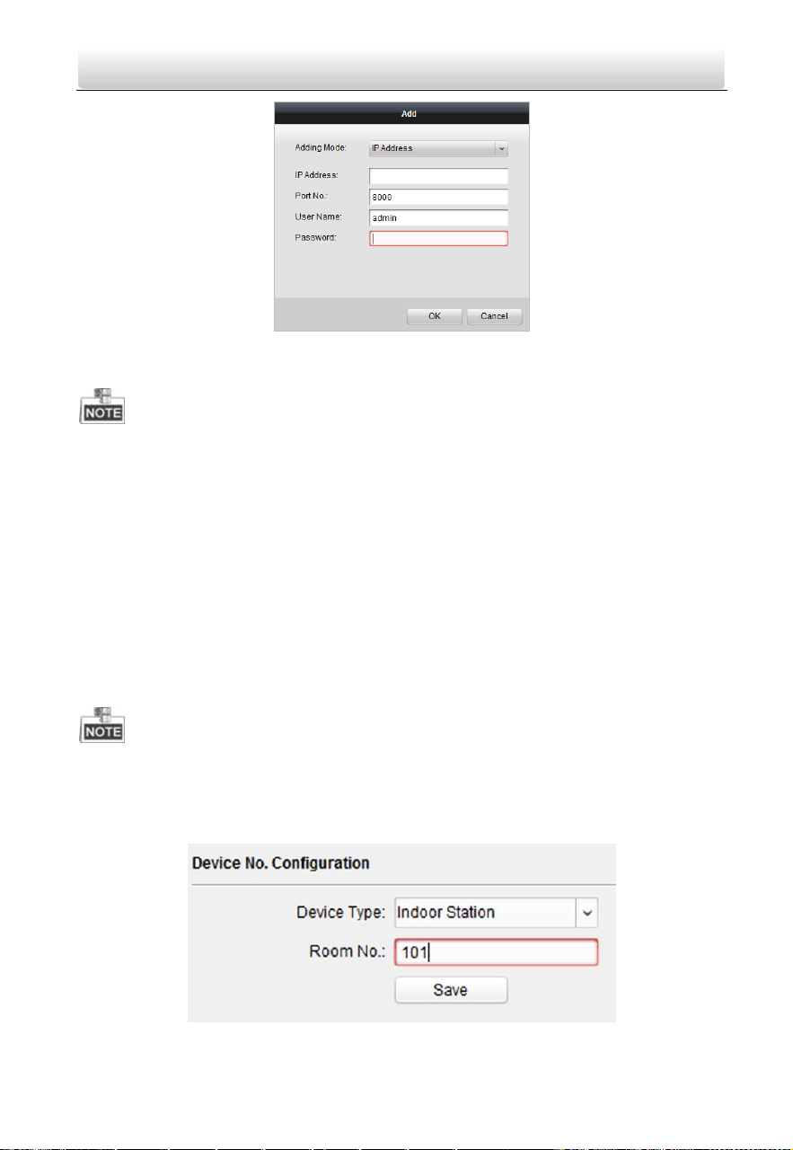
4.3.2 Adding by IP Address
Purpose:
You can add the device by entering IP address.
Steps:
1. Click the button to pop up the adding devices dialog box.
Figure 4-7 Click Adding Button
2. Select IP Address in the adding mode drop-down list.
3. Enter the IP address, and set the port No., user name and password of the device.
Two-Wire Video Intercom Bundle·Quick Start Guide
19
Figure 4-8 Add by IP Address
4. Click the OK button to add the device to the device list.
You cannot add the device(s) to the device list if the user name and password are not
identical.
When you add devices by IP Address, or IP Segment, the devices should be online
devices.
4.4 Set Indoor Station
4.4.1 Set Room No.
You can set the indoor station No. via batch configuration tool remotely. You can dial the
Room No. to call the indoor station resident.
Make sure you have activated the indoor station, and add it to the batch configuration
tool.
Steps:
1. Click Remote Configuration->ID Configuration to enter the ID configuration page.
Figure 4-9 Set the Indoor Station Room No.
Two-Wire Video Intercom Bundle·Quick Start Guide
20
2. Select the device type as Indoor Station, and set the Room No.
3. Click Save.
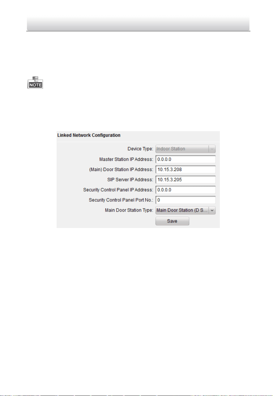
4.4.2 Set Linked Network Parameters
Linked network configuration is a basic setting for the communication among devices.
Make sure you have activated the indoor station, and add it to the batch configuration
tool.
Steps:
1. Click Remote Configuration->Network >Linked Network Configuration to enter the
linked network configuration page.
Figure 4-10 Linked Network Configuration
2. Enter the IP address of linked devices based on your requirements.
For example, we set the door station IP address as 10.15.3.208, so as to realize the
communication between the door station and the indoor station.
3. Click Save.
4.5 Add Device to App
You can realize remote control via the App.
You need to set up the app and add the door station to Hik-Connect by scanning the QR
code on the door station or entering the device serial number.
4.5.1 Set up the App
Before You Start
Make sure your mobile device has been connected to Wi-Fi.
Two-Wire Video Intercom Bundle·Quick Start Guide
21
Steps
1. Install Hik-Connect App and register a user account for iOS or Android.
1) Search “Hik-Connect” in App Store or Google Play™ to download and install the
App.
or
Figure 4-11 App Store/Google Play
2) Launch the App and follow the on-screen instructions to register a user account.
2. Start the Hik-Connect App, and log in to the App.
4.5.2 Add Device
Before You Start
Make sure devices have been activated.
Make sure the door station and the indoor station are linked and communicating
normally.
Make sure you have configured the Room No. and linked network parameters.
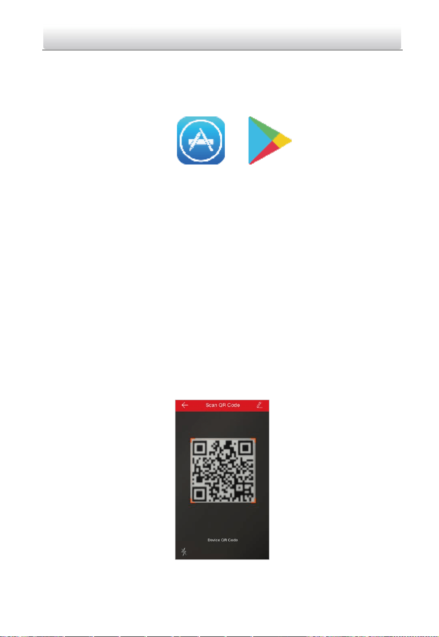
Mode 1 Add Device via QR Code
You can add the door station by scanning the QR code on the door station via the App.
Steps
1. On the App Home page, tap “+” on the upper-right corner to add the device.
2. Scan the QR code on the door station.
Figure 4-12 Scan QR Code
Two-Wire Video Intercom Bundle·Quick Start Guide
22
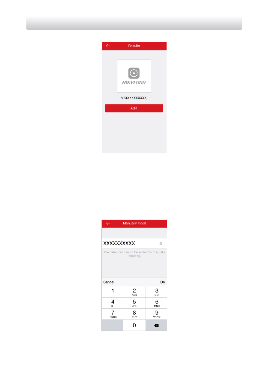
3. Tap Add to add the door station.
Figure 4-13 Device Result
Mode 2 Add Device via Serial No.
You can add the door station to the App by entering the device serial No. on the indoor
station interface.
Steps
1. On the App Home page, tap “+” on the upper-right corner to add the device.
2. Enter the device serial No., and click Add.
Figure 4-14 Enter Serial Number
Two-Wire Video Intercom Bundle·Quick Start Guide
23
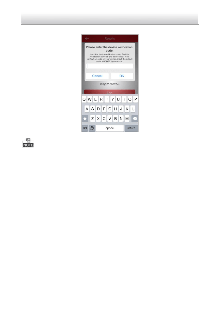
3. Enter the device verification code, and click OK.
Figure 4-15 Enter Verification Code
You can get the serial No. on the indoor station Maintenance page: Settings
->Maintenance.
The admin password of the indoor station is 123456.
The default device verification code is ABCDEF.

Two-Wire Video Intercom Bundle·Quick Start Guide
24
5 Video Intercom Operation
You can call the resident by pressing the call button.
Steps:
1. Press the call button of the doorbell.
2. The resident can receive/decline the video call, unlock the door, etc.
When the video intercom between you and the resident is realized, you can speak to
the resident, and the live view of door station will be displayed on the connected
indoor station.
When the door station is calling the resident, the door station will detect the
brightness of video automatically. When the brightness is lower than the expected
threshold, the supplement light will be enabled.
When the supplement light is enabled, the backlight of key will be auto-enabled,
otherwise, the door station will detect the brightness of live view and enable the
backlight of key when the brightness of live view is lower than expected threshold.
UD07733B-A

Two-Wire Video Intercom Bundle·Quick Start Guide
25
Appendix
Installation Notice
While installing the door station, please make sure that the distance between any two
devices is far as possible to avoid the howling and echo. The distance between two
devices is recommended to be longer than 10 meters.
Devices here refer to indoor station, door station, and video/audio distributor.

Two-Wire Video Intercom Bundle·Quick Start Guide
26