
Module Door Staon
User Manual

Legal Informaon
©2022 Hangzhou Hikvision Digital Technology Co., Ltd. All rights reserved.
About this Manual
The Manual includes instrucons for using and managing the Product. Pictures, charts, images and
all other informaon hereinaer are for descripon and explanaon only. The informaon
contained in the Manual is subject to change, without noce, due to rmware updates or other
reasons. Please nd the latest version of this Manual at the Hikvision website ( hps://
www.hikvision.com/ ).
Please use this Manual with the guidance and assistance of professionals trained in
supporng the
Product.
Trademarks
and other Hikvision's trademarks and logos are the properes of
Hikvision in various jurisdicons.
Other trademarks and logos menoned are the properes of their respecve owners.
Disclaimer
TO THE MAXIMUM EXTENT PERMITTED BY APPLICABLE LAW, THIS MANUAL AND THE PRODUCT
DESCRIBED, WITH ITS HARDWARE, SOFTWARE AND FIRMWARE, ARE PROVIDED "AS IS" AND "WITH
ALL FAULTS AND ERRORS". HIKVISION MAKES NO WARRANTIES, EXPRESS OR IMPLIED, INCLUDING
WITHOUT LIMITATION, MERCHANTABILITY, SATISFACTORY QUALITY, OR FITNESS FOR A PARTICULAR
PURPOSE. THE USE OF THE PRODUCT BY YOU IS AT YOUR OWN RISK. IN NO EVENT WILL HIKVISION
BE LIABLE TO YOU FOR ANY SPECIAL, CONSEQUENTIAL, INCIDENTAL, OR INDIRECT DAMAGES,
INCLUDING, AMONG OTHERS, DAMAGES FOR LOSS OF BUSINESS PROFITS, BUSINESS
INTERRUPTION, OR LOSS OF DATA, CORRUPTION OF SYSTEMS, OR LOSS OF DOCUMENTATION,
WHETHER BASED ON BREACH OF CONTRACT, TORT (INCLUDING NEGLIGENCE), PRODUCT LIABILITY,
OR OTHERWISE, IN CONNECTION WITH THE USE OF THE PRODUCT, EVEN IF HIKVISION HAS BEEN
ADVISED OF THE POSSIBILITY OF SUCH DAMAGES OR LOSS.
YOU ACKNOWLEDGE THAT THE NATURE OF THE INTERNET PROVIDES FOR INHERENT SECURITY
RISKS, AND HIKVISION SHALL NOT TAKE ANY RESPONSIBILITIES FOR ABNORMAL OPERATION,
PRIVACY LEAKAGE OR OTHER DAMAGES RESULTING FROM CYBER-ATTACK, HACKER ATTACK, VIRUS
INFECTION, OR OTHER INTERNET SECURITY RISKS; HOWEVER, HIKVISION WILL PROVIDE TIMELY
TECHNICAL SUPPORT IF REQUIRED.
YOU AGREE TO USE THIS PRODUCT IN COMPLIANCE WITH ALL APPLICABLE LAWS, AND YOU ARE
SOLELY RESPONSIBLE FOR ENSURING THAT YOUR USE CONFORMS TO THE APPLICABLE LAW.
ESPECIALLY, YOU ARE RESPONSIBLE, FOR USING THIS PRODUCT IN A MANNER THAT DOES NOT
INFRINGE ON THE RIGHTS OF THIRD PARTIES, INCLUDING WITHOUT LIMITATION, RIGHTS OF
PUBLICITY, INTELLECTUAL PROPERTY RIGHTS, OR DATA PROTECTION AND OTHER PRIVACY RIGHTS.
YOU SHALL NOT USE THIS PRODUCT FOR ANY PROHIBITED END-USES, INCLUDING THE
Module Door Staon User Manual
i

DEVELOPMENT OR PRODUCTION OF WEAPONS OF MASS DESTRUCTION, THE DEVELOPMENT OR
PRODUCTION OF CHEMICAL OR BIOLOGICAL WEAPONS, ANY ACTIVITIES IN THE CONTEXT RELATED
TO ANY NUCLEAR EXPLOSIVE OR UNSAFE NUCLEAR FUEL-CYCLE, OR IN SUPPORT OF HUMAN
RIGHTS ABUSES.
IN THE EVENT OF ANY CONFLICTS BETWEEN THIS MANUAL AND THE APPLICABLE LAW, THE LATTER
PREVAILS.
Data Protecon
During the use of device, personal data will be collected, stored and processed. To protect data,
the development of Hikvision devices incorporates privacy by design principles. For example, for
device with facial recognion features, biometrics data is stored in your device with encrypon
method; for ngerprint device, only ngerprint template will be saved, which is impossible to
reconstruct a ngerprint image.
As data controller, you are advised to collect, store, process and transfer data in accordance with
the applicable data
protecon laws and regulaons, including without limitaon, conducng
security controls to safeguard personal data, such as, implemenng reasonable administrave and
physical security controls, conduct periodic reviews and assessments of the
eecveness of your
security controls.
Module Door Staon User Manual
ii
Symbol Convenons
The symbols that may be found in this document are dened as follows.
Symbol Descripon
Danger
Indicates a hazardous situaon which, if not avoided, will or could
result in death or serious injury.
Cauon
Indicates a potenally hazardous situaon which, if not avoided, could
result in equipment damage, data loss, performance degradaon, or
unexpected results.
Note
Provides addional informaon to emphasize or supplement
important points of the main text.
Module Door Staon User Manual
iii

Regulatory Informaon
FCC Informaon
Please take aenon that changes or modicaon not expressly approved by the party responsible
for compliance could void the user's authority to operate the equipment.
FCC compliance: This equipment has been tested and found to comply with the limits for a Class B
digital device, pursuant to part 15 of the FCC Rules. These limits are designed to provide
reasonable
protecon against harmful interference in a residenal installaon. This equipment
generates, uses and can radiate radio frequency energy and, if not installed and used in accordance
with the
instrucons, may cause harmful interference to radio communicaons. However, there is
no guarantee that interference will not occur in a parcular installaon. If this equipment does
cause harmful interference to radio or television
recepon, which can be determined by turning
the equipment o and on, the user is encouraged to try to correct the interference by one or more
of the following measures:
—Reorient or relocate the receiving antenna.
—Increase the
separaon between the equipment and receiver.
—Connect the equipment into an outlet on a circuit
dierent from that to which the receiver is
connected.
—Consult the dealer or an experienced radio/TV technician for help
FCC
Condions
This device complies with part 15 of the FCC Rules. Operaon is subject to the following two
condions:
1. This device may not cause harmful interference.
2. This device must accept any interference received, including interference that may cause
undesired
operaon.
Module Door Staon User Manual
iv
EU Conformity Statement
This product and - if applicable - the supplied accessories too are marked with "CE"
and comply therefore with the applicable harmonized European standards listed
under the EMC Direcve 2014/30/EU, the RoHS Direcve 2011/65/EU
2012/19/EU (WEEE direcve): Products marked with this symbol cannot be disposed
of as unsorted municipal waste in the European Union. For proper recycling, return
this product to your local supplier upon the purchase of equivalent new equipment,
or dispose of it at designated
collecon points. For more informaon see:
www.recyclethis.info
2006/66/EC (baery direcve): This product contains a baery that cannot be
disposed of as unsorted municipal waste in the European Union. See the product
documentaon for specic baery informaon. The baery is marked with this
symbol, which may include
leering to indicate cadmium (Cd), lead (Pb), or mercury
(Hg). For proper recycling, return the
baery to your supplier or to a designated
collecon point. For more informaon see:www.recyclethis.info
Industry Canada ICES-003 Compliance
This device meets the CAN ICES-3 (B)/NMB-3(B) standards requirements.
This device complies with Industry Canada licence-exempt RSS standard(s).
Operaon is subject to
the following two condions:
1. this device may not cause interference, and
2. this device must accept any interference, including interference that may cause undesired
operaon of the device.
Le présent appareil est conforme aux CNR d'Industrie Canada applicables aux appareils
radioexempts de licence.
L'exploitaon est autorisée aux deux condions suivantes :
1. l'appareil ne doit pas produire de brouillage, et
2.
l'ulisateur de l'appareil doit accepter tout brouillage radioélectrique subi, même si le brouillage
est
suscepble d'en compromere le fonconnement.
Under Industry Canada regulaons, this radio transmier may only operate using an antenna of a
type and maximum (or lesser) gain approved for the
transmier by Industry Canada. To reduce
potenal radio interference to other users, the antenna type and its gain should be so chosen that
the equivalent isotropically radiated power (e.i.r.p.) is not more than that necessary for successful
communicaon.
Conformément à la réglementaon d'Industrie Canada, le présent émeeur radio peut fonconner
avec une antenne d'un type et d'un gain maximal (ou inférieur) approuvé pour l'émeeur par
Industrie Canada. Dans le but de réduire les risques de brouillage radioélectrique à l'intenon des
autres
ulisateurs, il faut choisir le type d'antenne et son gain de sorte que la puissance isotrope
Module Door Staon User Manual
v

rayonnée équivalente (p.i.r.e.) ne dépasse pas l'intensité nécessaire à l'établissement d'une
communicaon sasfaisante.
This equipment should be installed and operated with a minimum distance 20cm between the
radiator and your body.
Cet équipement doit être installé et ulisé à une distance minimale de 20 cm entre le radiateur et
votre corps.
Module Door Staon User Manual
vi

Contents
Chapter 1 Appearance ................................................................................................................ 1
Chapter 2 Terminal and Wiring ................................................................................................. 10
2.1 Terminal Descripon ............................................................................................................ 10
2.2 Module Door Staon Wiring ................................................................................................ 15
2.2.1 Door Lock Wiring ........................................................................................................ 15
2.2.2 Door Contact Wiring ................................................................................................... 17
2.2.3 Exit Buon Wiring ....................................................................................................... 18
Chapter 3 Installaon ............................................................................................................... 19
3.1
Congure Sub Module Address ........................................................................................... 19
3.2 One-Module Installaon ...................................................................................................... 20
3.2.1 One-Module Surface Mounng .................................................................................. 20
3.2.2 One-Module Flush
Mounng ...................................................................................... 26
3.3 Two-Module Installaon ...................................................................................................... 32
3.3.1 Two-Module Surface Mounng .................................................................................. 32
3.3.2 Two-Module Flush
Mounng ...................................................................................... 37
3.4 Three-Module Installaon ................................................................................................... 43
3.4.1 Three-Module Surface Installaon .............................................................................. 43
3.4.2 Three-Module Flush
Mounng ................................................................................... 50
3.5 More-Than-Three Module Installaon ................................................................................ 55
3.5.1 More-than-Three Module Surface Mounng ............................................................. 55
3.5.2 More-Than-Three Module Flush
Mounng ................................................................ 64
Chapter 4 Acvaon ................................................................................................................. 73
4.1 Acvate Device via Client Soware ...................................................................................... 73
4.2 Edit Network Parameters ..................................................................................................... 73
Chapter 5
Conguraon via Client Soware ............................................................................. 75
5.1 Device Management ............................................................................................................ 75
Module Door Staon User Manual
vii

5.1.1 Add Online Device ....................................................................................................... 75
5.1.2 Add Device by IP Address ............................................................................................ 77
5.1.3 Add Device by IP Segment .......................................................................................... 77
5.2 Live View via Door
Staon ................................................................................................... 77
5.3 Remote Conguraon .......................................................................................................... 77
5.3.1 Device Management ................................................................................................... 77
5.3.2 Local Parameters Sengs ........................................................................................... 78
5.3.3 System Sengs ........................................................................................................... 80
5.3.4 Network Sengs ......................................................................................................... 82
5.3.5 Video & Audio Sengs ............................................................................................... 87
5.3.6 Image Sengs ............................................................................................................. 89
5.3.7 Event Sengs .............................................................................................................. 92
5.3.8 Schedule
Sengs ........................................................................................................ 96
5.3.9 Intercom
Sengs ........................................................................................................ 97
5.3.10 Access Control Sengs ........................................................................................... 101
5.3.11 Theme Sengs ....................................................................................................... 103
5.4 Video Intercom
Sengs ..................................................................................................... 104
5.4.1 Receive Call from Door Staon ................................................................................. 104
5.4.2 Search Call Logs ......................................................................................................... 105
5.4.3 Upload Armed
Informaon ....................................................................................... 107
Appendix A. Communicaon Matrix and Device Command .................................................... 108
Module Door Staon User Manual
viii
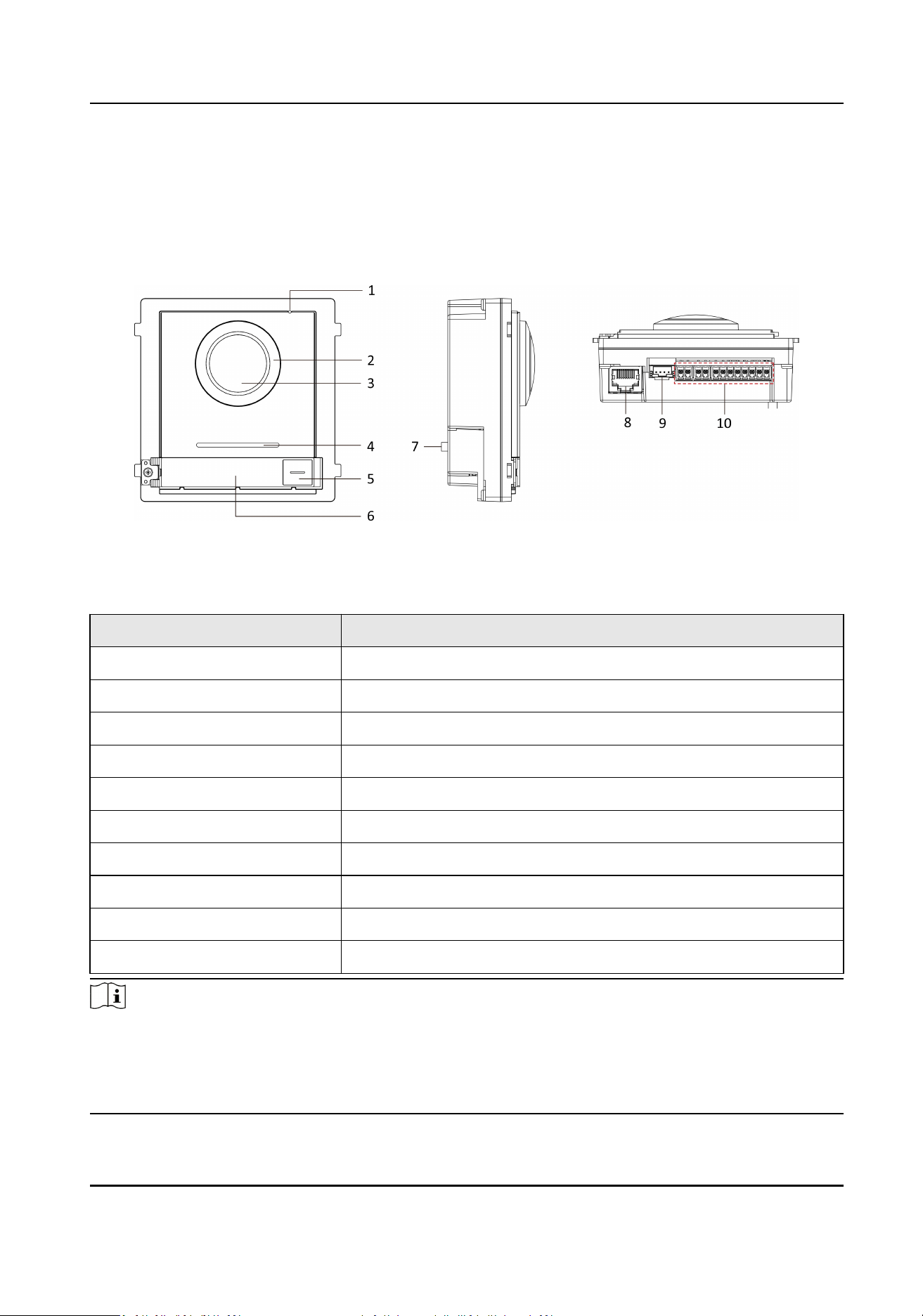
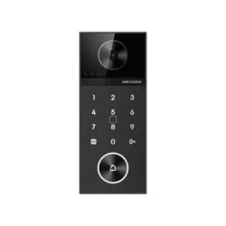
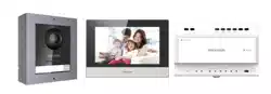
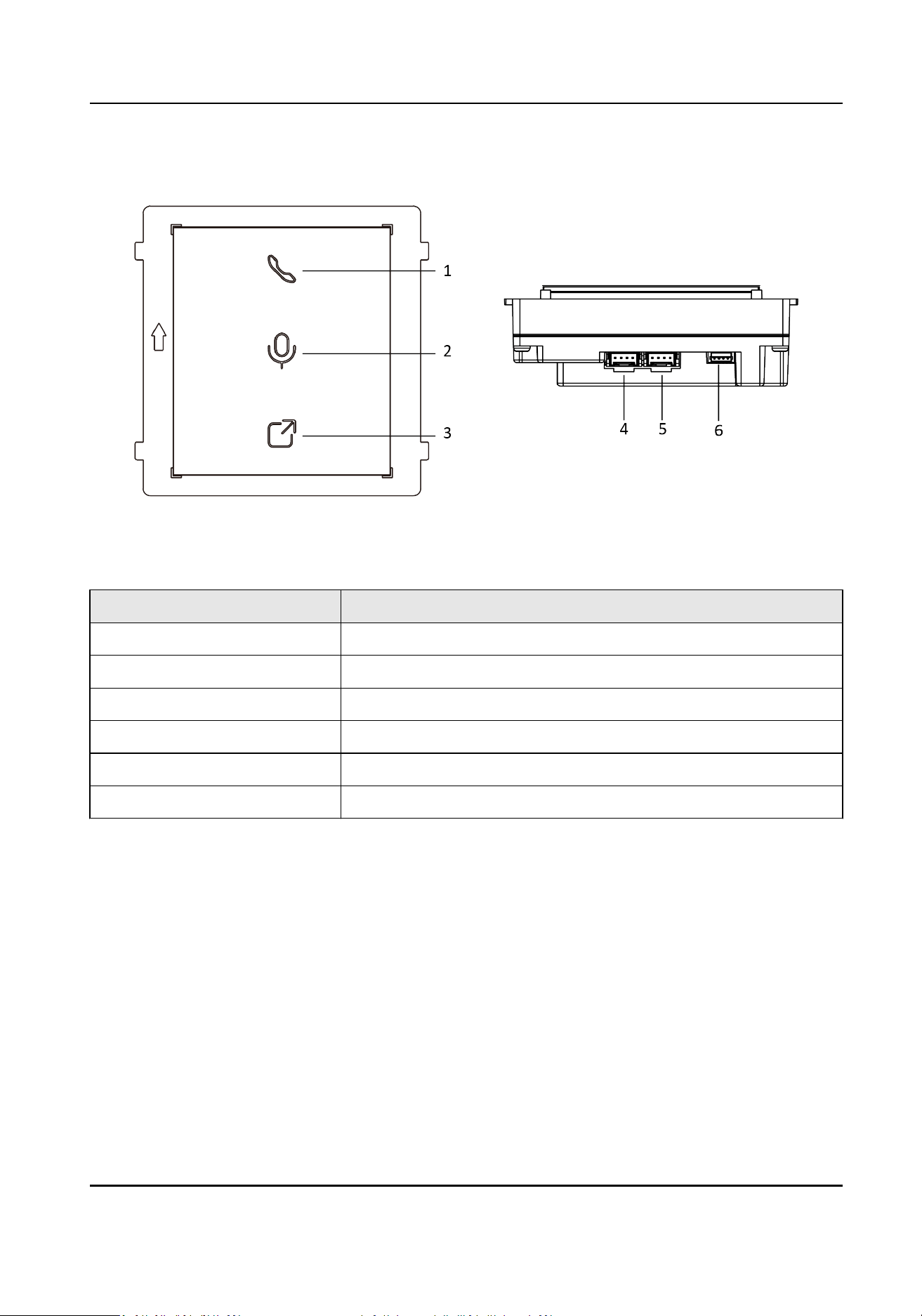
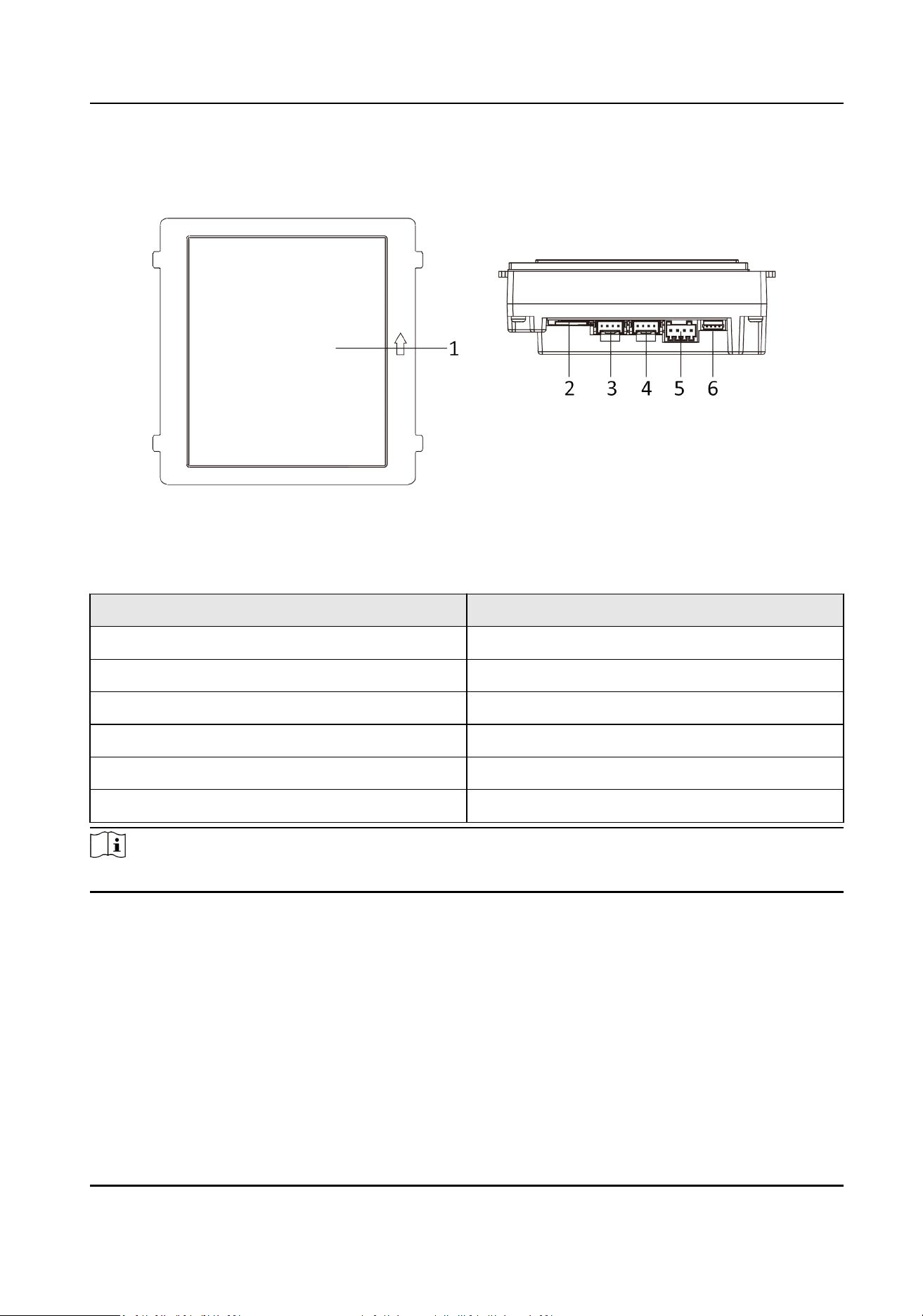
Chapter 1 Appearance
Main Unit
Figure 1-1 Main Unit Appearance
Table 1-1 Appearance Descripon
No. Descripon
1 Microphone
2 Low Illuminaon IR Supplement Light
3 Built-in Camera
4 Loudspeaker
5 Call Buon
6 Nametag
7 TAMPER
8 Network Interface
9 Module-Connecng Interface (output)
10 Terminals
Note
●
Nametag area supports insert customized name card. The suggested card size is: 58 (L) x 11.7(W)
mm.
●
The module connecng interface is used to connect other funcon module, such as nametag
module, keypad module, card reader module, etc. All these modules are known as sub module.
Module Door Staon User Manual
1
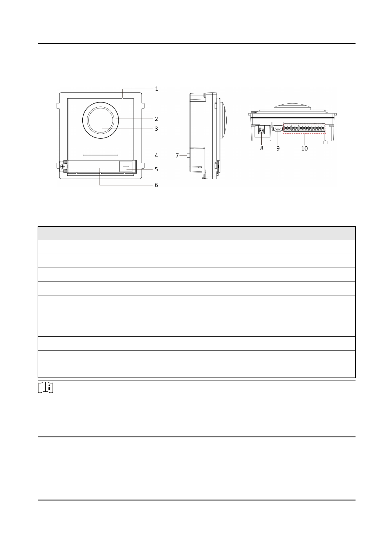
Two-Wire Main Unit
Figure 1-2 Two-Wire Main Unit
Table 1-2 Appearance Descripon
No. Descripon
1 Microphone
2 Low Illuminaon IR Supplement Light
3 Built-in Camera
4 Loudspeaker
5 Call Buon
6 Nametag
7 TAMPER
8 Two-Wire Interface (24 VDC Power Input)
9 Module-Connecng Interface (output)
10 Terminals
Note
●
Nametag area supports insert customized name card. The suggested card size is: 58 (L) x 11.7(W)
mm.
●
The module connecng interface is used to connect other funcon module, such as nametag
module, keypad module, card reader module, etc. All these modules are known as sub module.
Module Door Staon User Manual
2
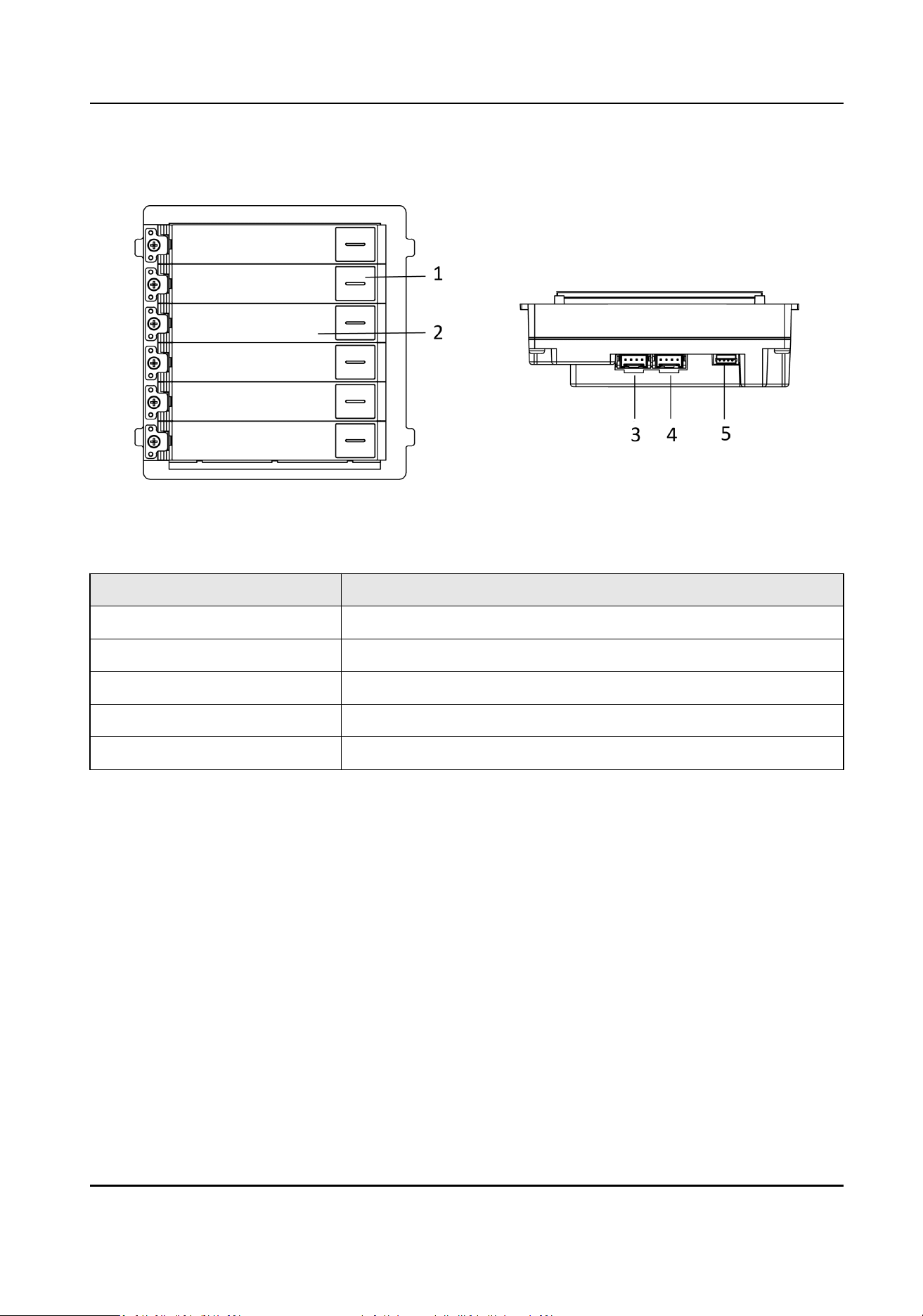
Nametag Module
Figure 1-3 Nametag Module Appearance
Table 1-3 Appearance Descripon
No. Descripon
1 Call Buon
2 Nametag
3 Module-Connecng Interface (output)
4 Module-Connecng Interface (input)
5 Debugging Port
Module Door Staon User Manual
3
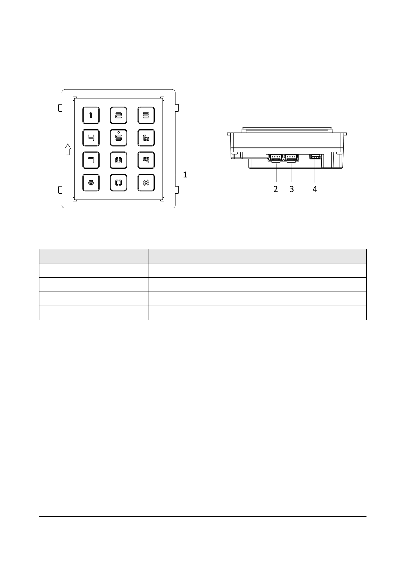
Keypad Module
Figure 1-4 Keypad Module Appearance
Table 1-4 Appearance Descripon
No. Descripon
1 Buon
2 Module-Connecng Interface (output)
3 Module-Connecng Interface (input)
4 Debugging Port
Module Door Staon User Manual
4
Indicator Module
Figure 1-5 Indicator Module
Table 1-5 Appearance Descripon
No. Descripon
1 Calling Indicator
2 Two-way Audio Indicator
3 Unlock Indicator
4 Module-connecng Interface (output)
5 Module-connecng Interface(input)
6 Debugging Port
Module Door Staon User Manual
5
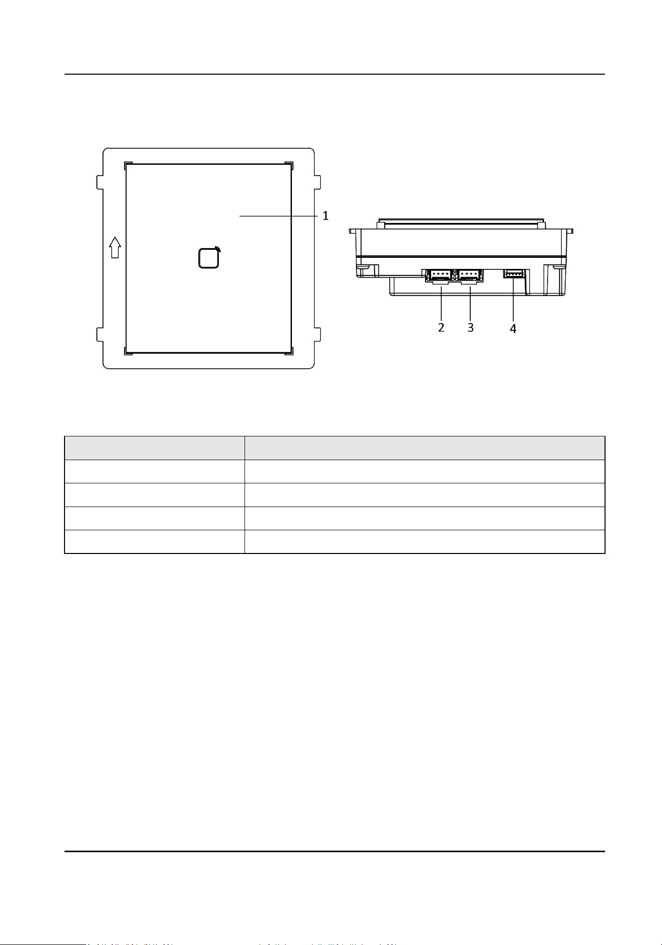
Card Reader Module
Figure 1-6 Card Reader Module
Table 1-6 Appearance Descripon
No. Descripon
1 Card Reading Area
2 Module-connecng Interface (output)
3 Module-connecng Interface(input)
4 Debugging Port
Module Door Staon User Manual
6
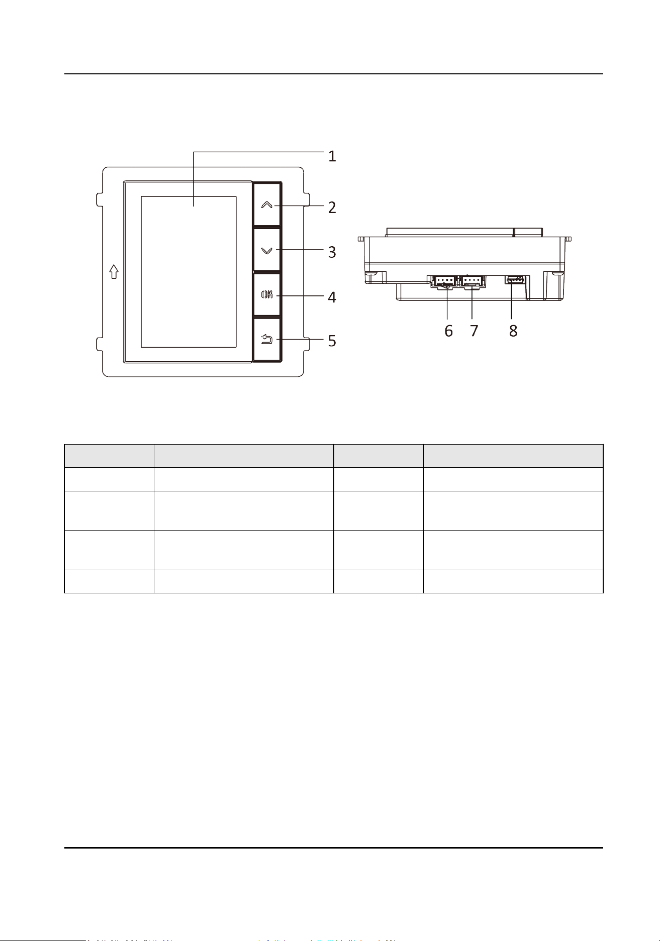
Display Module
Figure 1-7 Display Module
Table 1-7 Descripon
No. Descripon No. Descripon
1 Screen 5 Back Buon
2 Up Buon 6 Module-connecng Interface
(output)
3 Down Buon 7 Module-connecng Interface
(input)
4 Conrm Buon 8 Debug Port
Module Door Staon User Manual
7
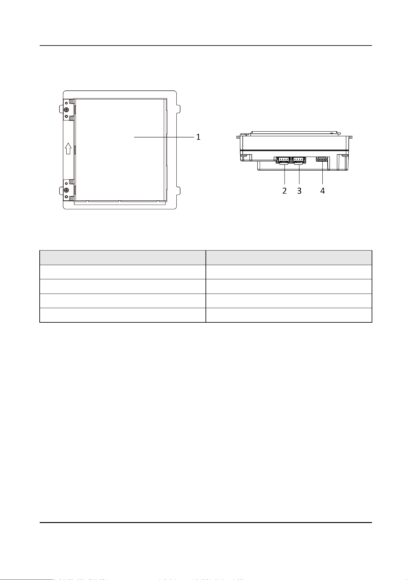
Informaon Module
Figure 1-8 Informaon Module
Table 1-8 Descripon
No. Descripon
1 Display Area
2 Module-connecng Interface (output)
3 Module-connecng Interface (input)
4 Debugging Port
Module Door Staon User Manual
8
Touch-Display Module
Figure 1-9 Touch-Display Module
Table 1-9 Descripon
No. Descripon
1 Touch-Display Area
2 TF Card Slot
3 Module-connecng Interface (output)
4 Module-connecng Interface (input)
5 Video & Audio Terminal
6 Debugging Port
Note
The debugging port is used for debugging only.
Module Door Staon User Manual
9
Chapter 2 Terminal and Wiring
2.1 Terminal Descripon
The power source should be qualied and meet limited power source or PS2 requirements
according to IEC 60950-1 or IEC 62368-1 standard.
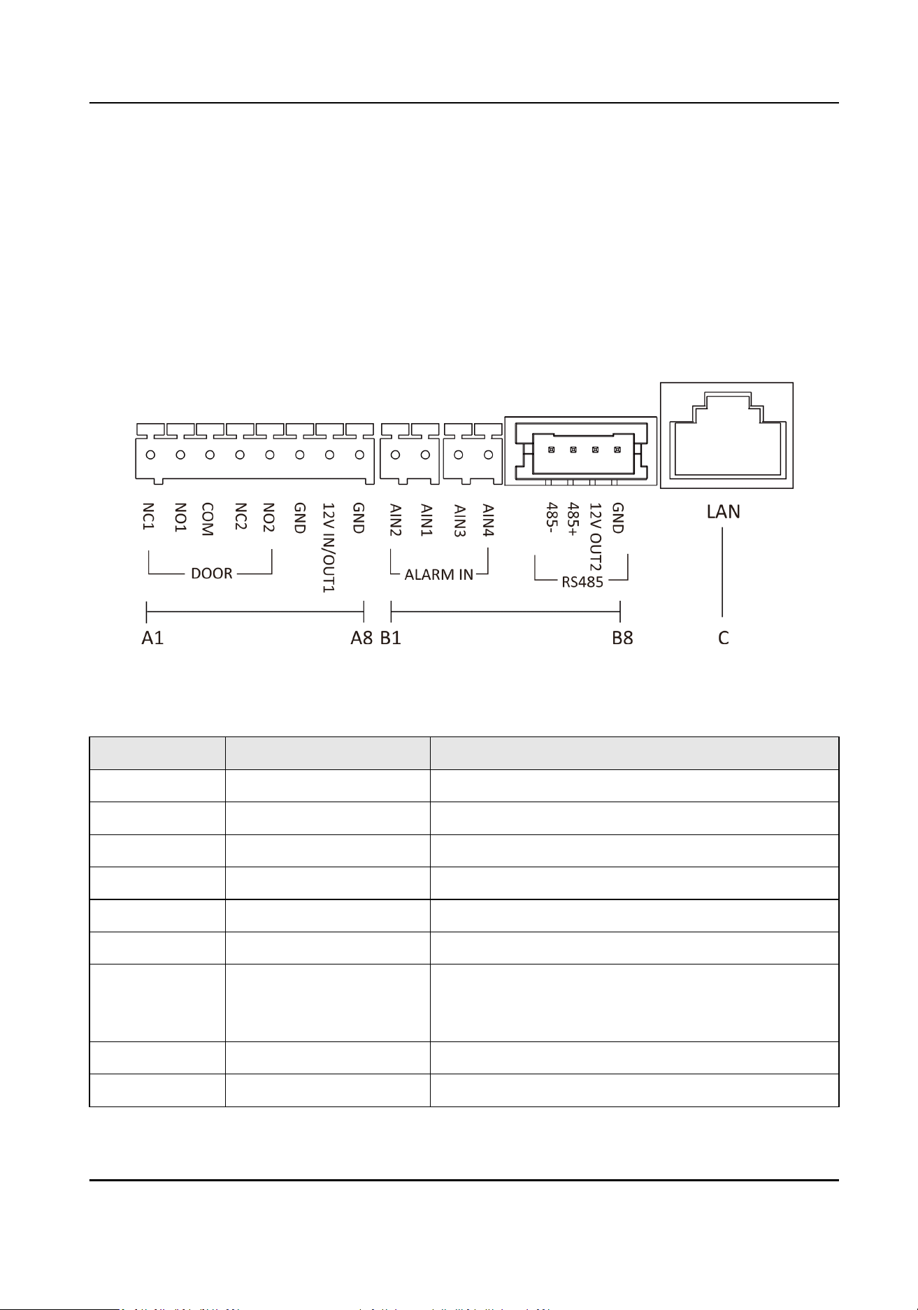
Main Unit Terminals
Figure 2-1 Main Unit Terminals
Table 2-1 Descripons of Terminals and Interfaces
No. Interface Descripon
A1 NC1 Door Lock Relay Output (NC)
A2 NO1 Door Lock Relay Output (NO)
A3 COM Common Interface
A4 NC2 Door Lock Relay Output (NC)
A5 NO2 Door Lock Relay Output (NO)
A6 GND Grounding
A7 12 V IN/OUT1
●
The power output is 12 V, 500mA.
●
When the device is powered by PoE, the 12V
IN/OUT interface can supply power to the lock.
A8 GND Grounding
B1 AIN2 For the access of Door Magnec 2
Module Door Staon User Manual
10
No. Interface Descripon
B2 AIN1 For the access of Door Magnec 1
B3 AIN3 For the access of Exit Buon 1
B4 AIN4 For the access of Exit Buon 2
B5 485- Module-connecng Interface
B6 485+
B7 12 V OUT2
B8 GND
C LAN PoE Network Interface(Supports IEEE 802.3af)
Table 2-2 Power Supply
Power Supply Door Staon Power Output
PoE (802.3af) DC 12V OUT1/DC 12V OUT2
6 W MAX in total
DC 12 V DC 12V OUT2
18 W MAX
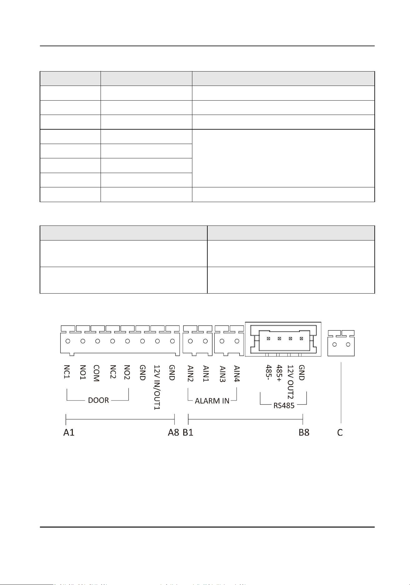
Two-Wire Main Unit Terminal
Figure 2-2 Two-Wire Main Unit Terminal
Module Door Staon User Manual
11
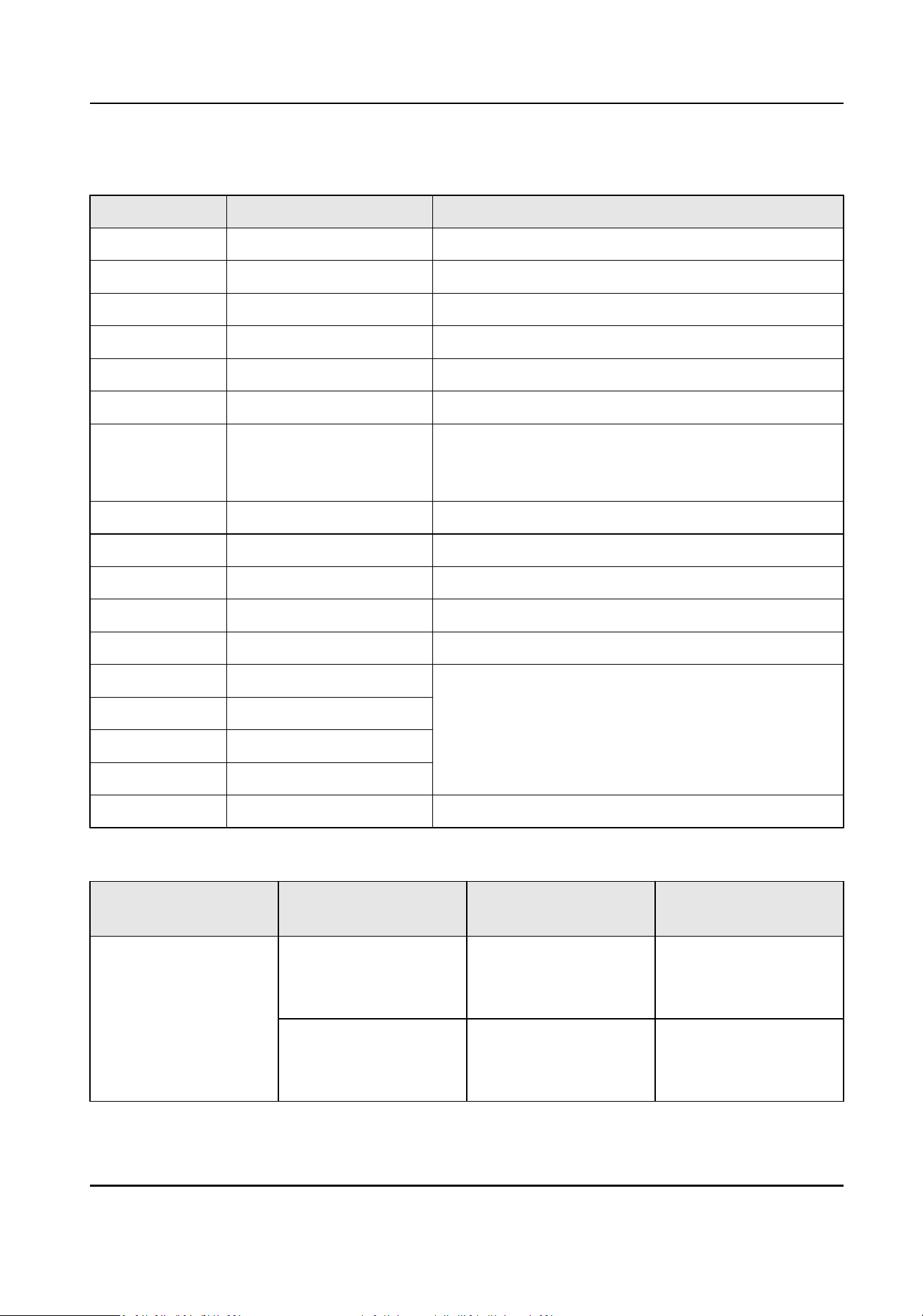
Table 2-3 Descripons of Terminals and Interfaces
No. Interface Descripon
A1 NC1 Door Lock Relay Output (NC)
A2 NO1 Door Lock Relay Output (NO)
A3 COM Common Interface
A4 NC2 Door Lock Relay Output (NC)
A5 NO2 Door Lock Relay Output (NO)
A6 GND Grounding
A7 12 V IN/OUT1
●
The power output is 12 V, 500mA.
●
When the device is powered by PoE, the 12V
IN/OUT 1 interface can supply power to the lock.
A8 GND Grounding
B1 AIN2 For the access of Door Magnec 2
B2 AIN1 For the access of Door Magnec 1
B3 AIN3 For the access of Exit Buon 1
B4 AIN4 For the access of Exit Buon 2
B5 485- Module-connecng Interface
B6 485+
B7 12 V OUT2
B8 GND
C Two-Wire Interface Two-Wire Interface
Table 2-4 Power Supply
Power Supply Distributor Model Distributor Power
Output
Door Staon Power
Output
DC 24 V DS-KAD704-Y DC 24 V OUT
8 W MAX
DC 12V OUT1/DC 12V
OUT2
3 W MAX in total
DS-KAD706-Y DC 24 V OUT
16 W MAX
DC 12V OUT1/DC 12V
OUT2
10 W MAX in total
Module Door Staon User Manual
12
Power Supply Distributor Model Distributor Power
Output
Door Staon Power
Output
DS-KAD706-YP(C) DC 24 V OUT
16 W MAX
DC 12V OUT1/DC 12V
OUT2
10 W MAX in total
DC 12 V / / DC 12V OUT2
18 W MAX
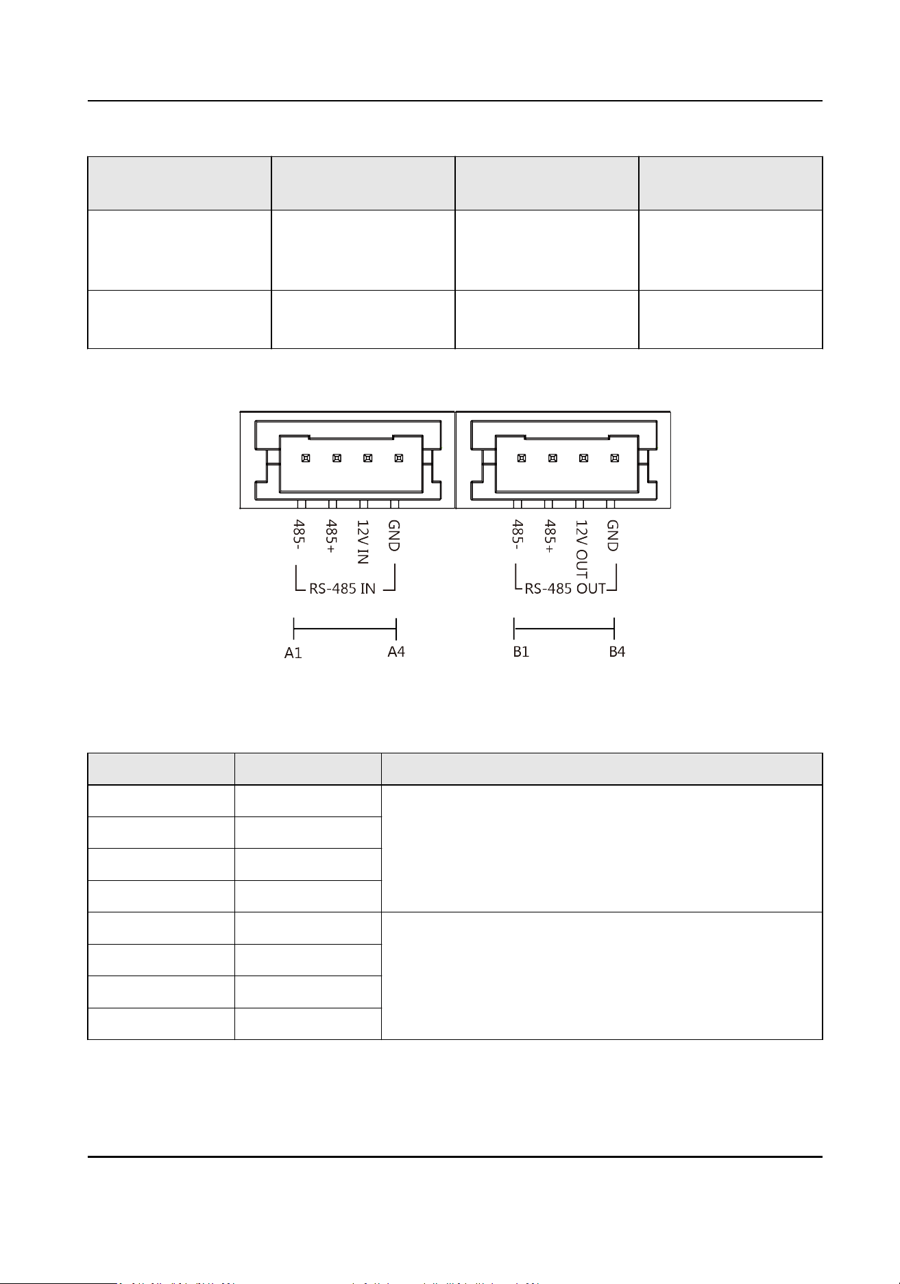
Sub Module Terminal (Except Touch-Display Module)
Figure 2-3 Sub Module Terminal (Except Touch-Display Module)
Table 2-5 Descripon
No. Interface Descripon
A1 485- Module-Connecng Interface (Input)
A2 485+
A3 12V IN
A4 GND
B1 485- Module-Connecng Interface (Output)
B2 485+
B3 12V OUT
B4 GND
Module Door Staon User Manual
13
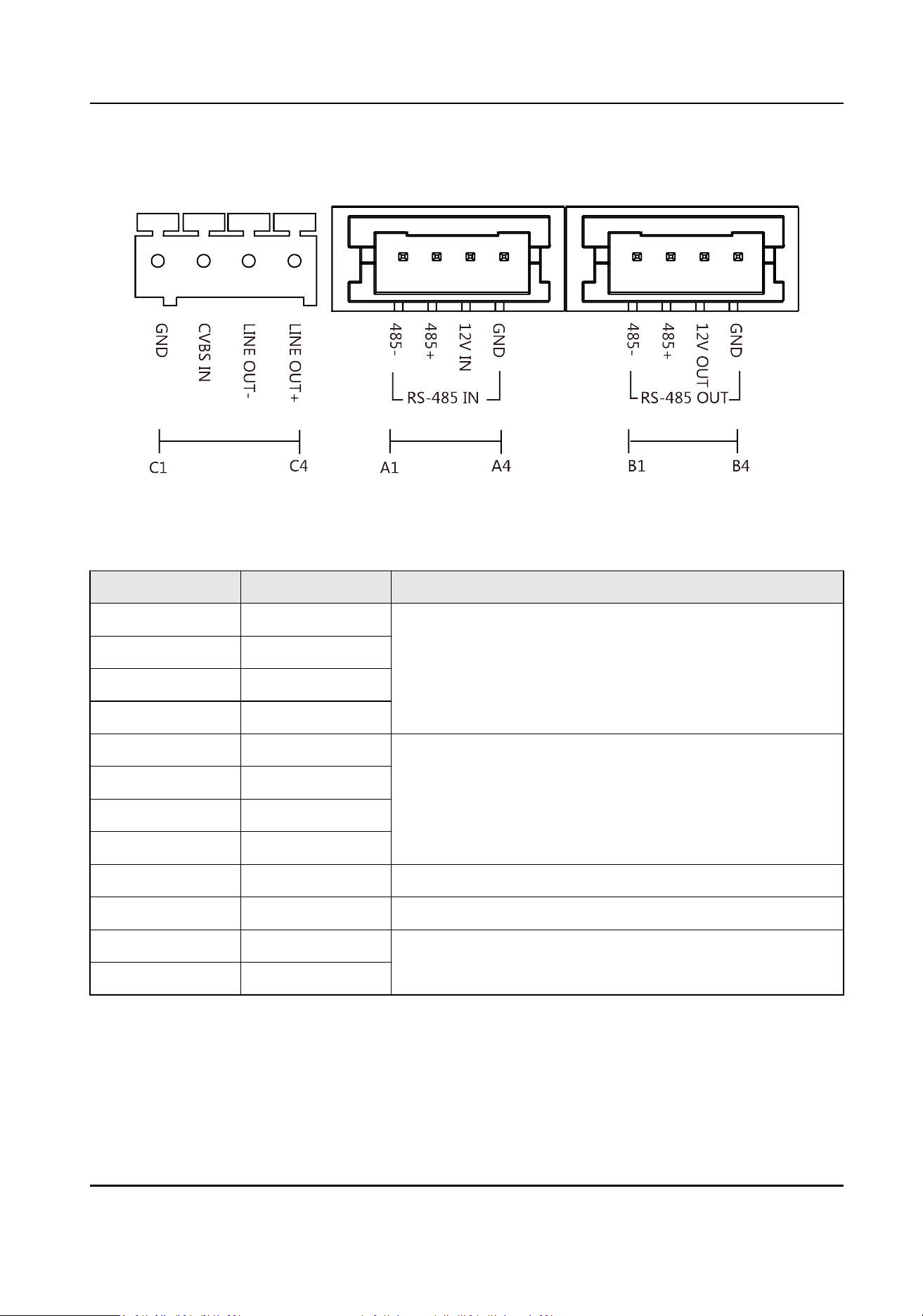
Touch-Display Module
Figure 2-4 Touch-Display Module
Table 2-6 Descripon
No. Interface Descripon
A1 485- Module-Connecng Interface (Input)
A2 485+
A3 12V IN
A4 GND
B1 485- Module-Connecng Interface (Output)
B2 485+
B3 12V OUT
B4 GND
C1 GND Grounding Interface
C2 CVSB IN Composite Video Broadcast Signal Input (Reserved)
C3 LINEOUT- Audio Output (Reserved)
C4 LINEOUT+
Module Door Staon User Manual
14
2.2 Module Door Staon Wiring
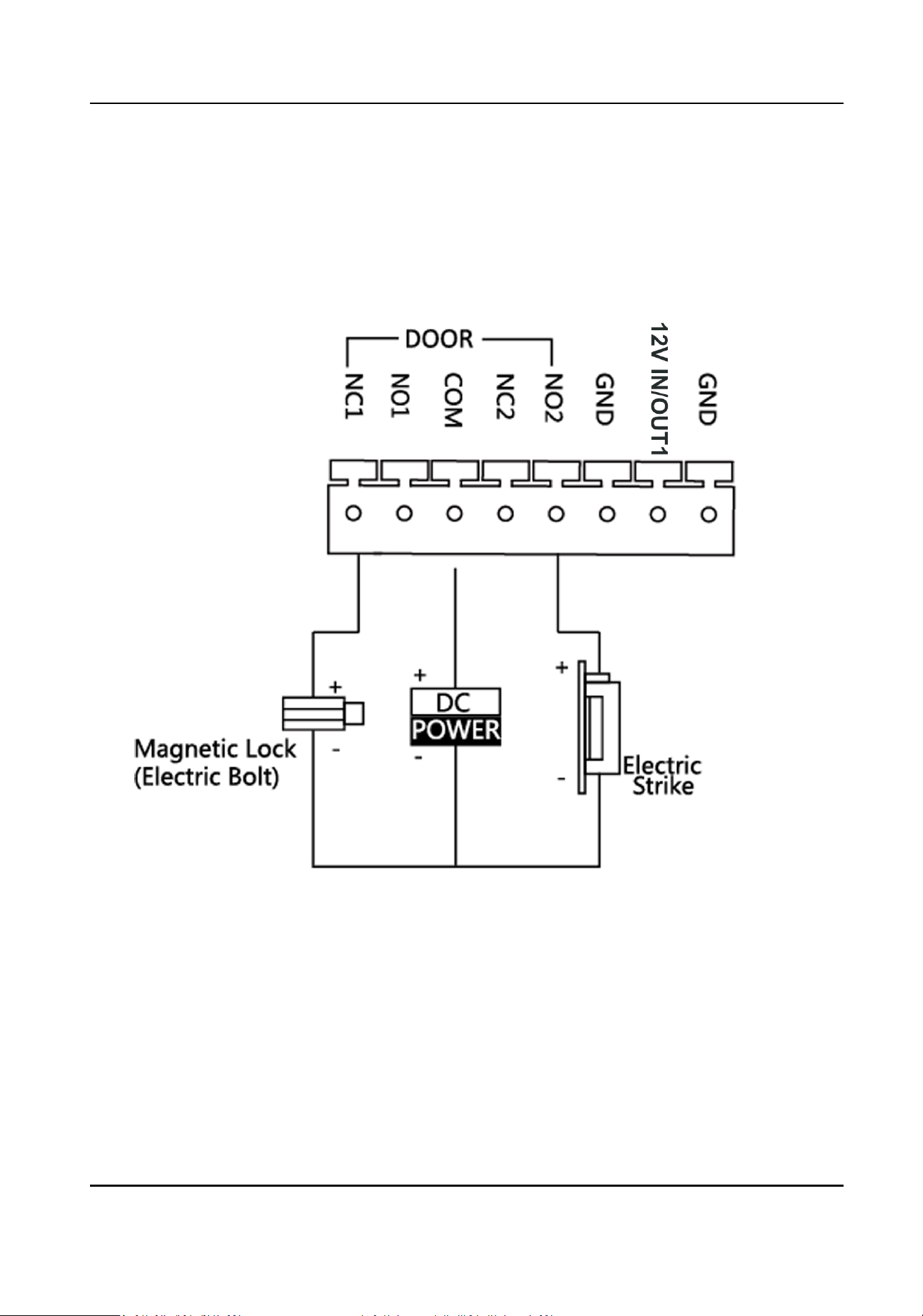
2.2.1 Door Lock Wiring
Figure 2-5 Door Lock Wiring
Module Door Staon User Manual
15
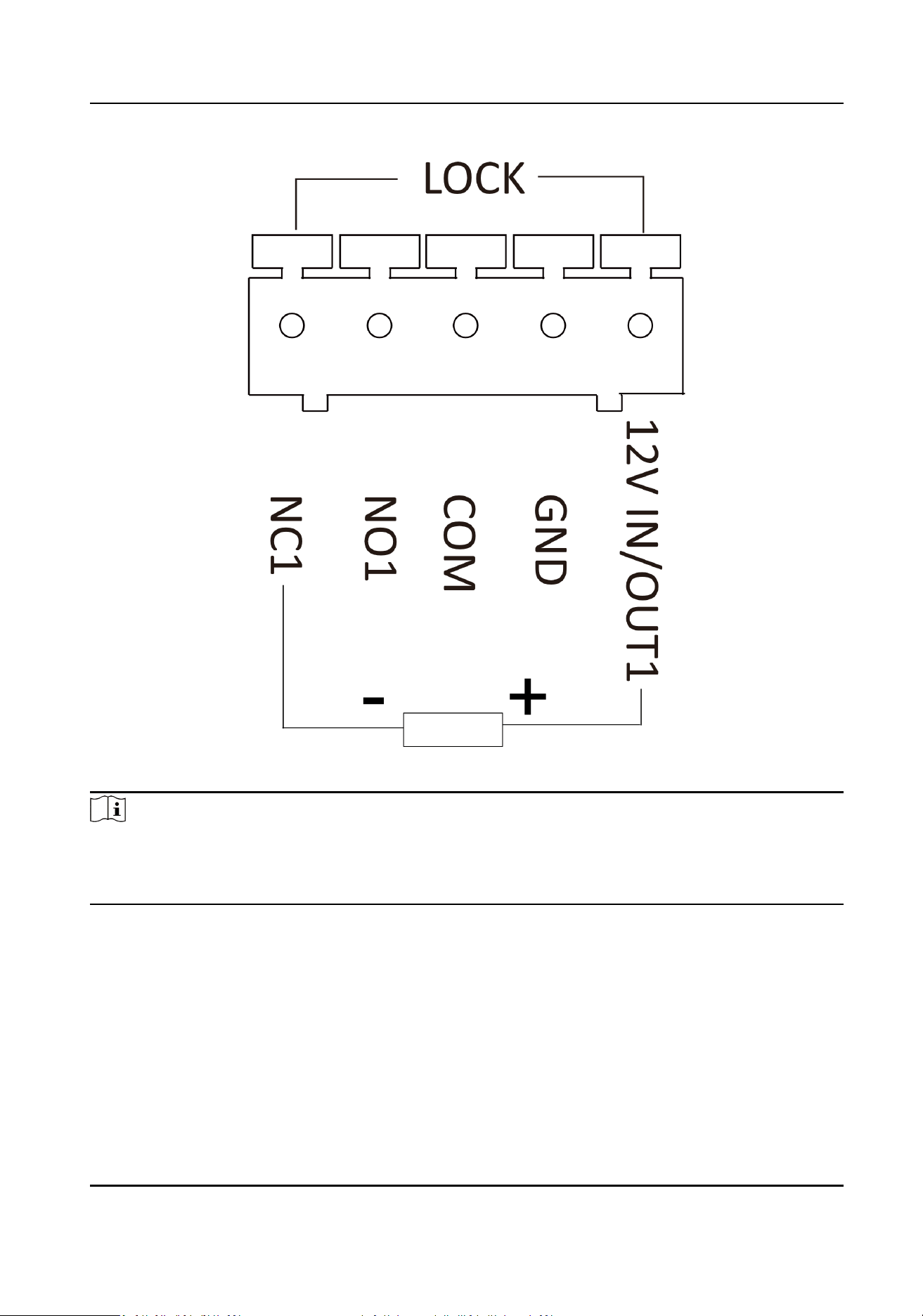
Figure 2-6 Lock Wiring when powered by PoE
Note
●
When the device is powered by PoE, the 12V IN/OUT interface can supply power to the lock.
●
Terminal NC1/COM is set as default for accessing magnec lock/electric bolt; terminal NO2/COM
is set as default for accessing electric strike.
Module Door Staon User Manual
16
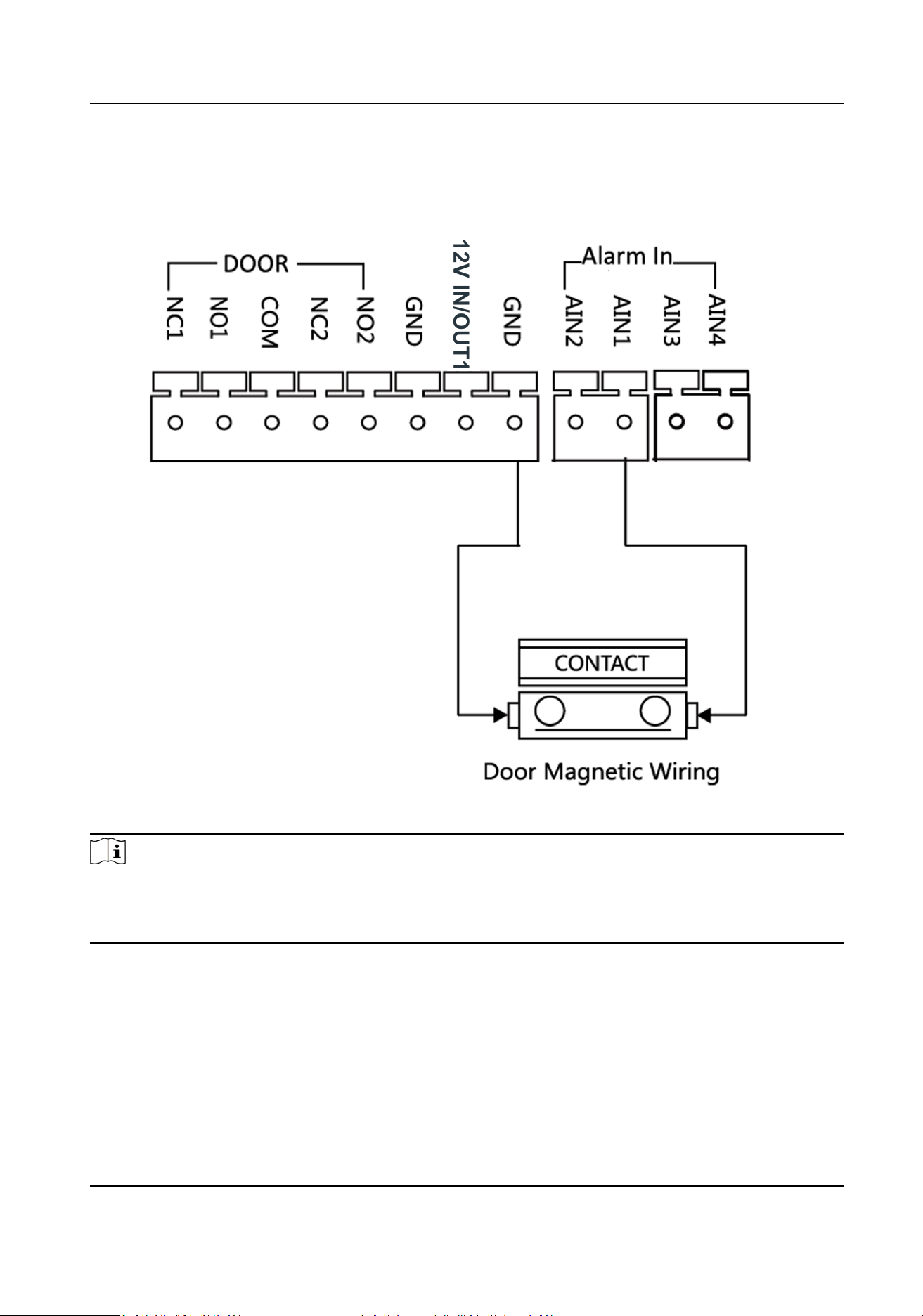
2.2.2 Door Contact Wiring
Figure 2-7 Door Contact Wiring
Note
AIN1 and AIN2 are defaulted to connect door contact. Door contact connected to AIN1 detects
status of the lock that connected to NC1/NO1; Door contact connected to AIN2 detects the status
of the lock connected to NC2/NO2.
Module Door Staon User Manual
17
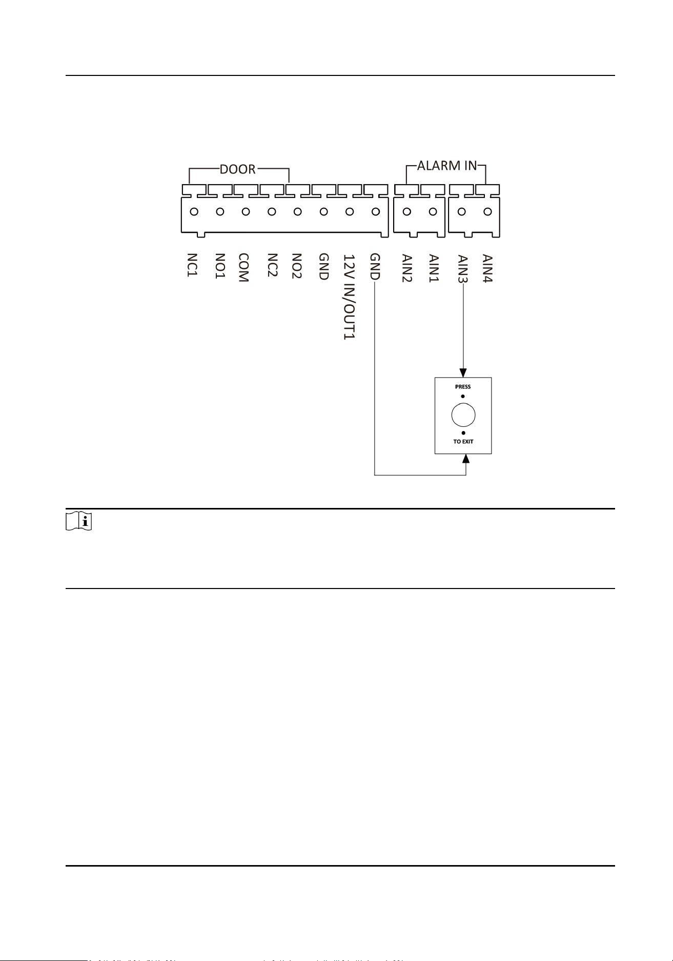
2.2.3 Exit Buon Wiring
Figure 2-8 Exit Buon Wiring
Note
AIN3 and AIN4 are set as default for connecng exit buon. Exit buon connected to AIN3 opens
the lock connected to NC1/NO1; Exit buon connected to AIN4 controls the lock that connected to
NC2/NO2.
Module Door Staon User Manual
18
Chapter 3 Installaon
Note
●
Make sure the device in the package is in good condion and all the assembly parts are included.
●
Sub module must work along with the main unit.
●
Set the sub module address before start the installaon steps.
●
Make sure the place for surface
mounng is at.
●
Make sure all the related equipment is
power-o during the installaon.
●
Tools that you need to prepare for installaon:
Drill (ø6), cross screwdriver (PH1*150 mm), and gradienter.
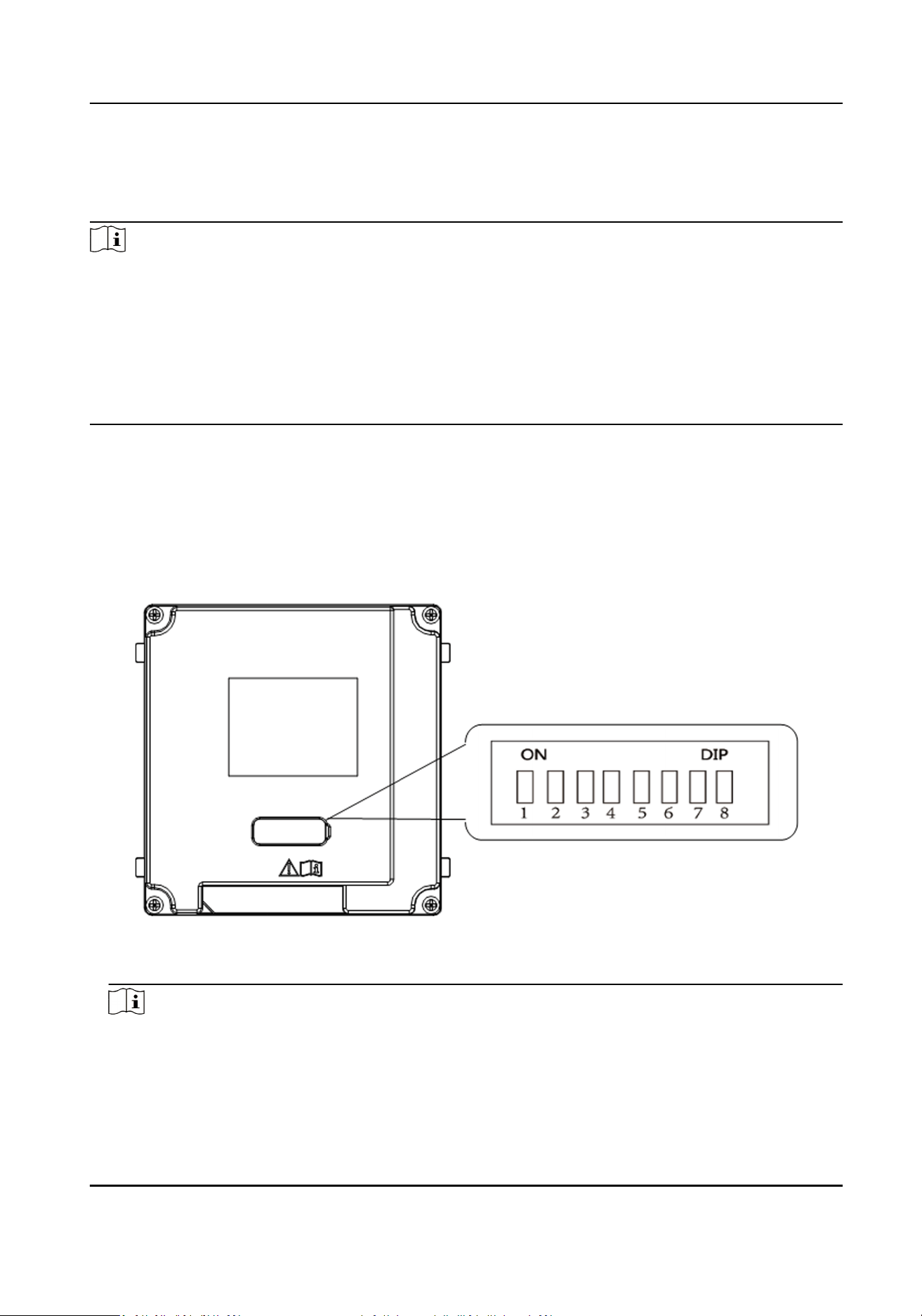
3.1 Congure Sub Module Address
You need to set the sub module address via DIP switch before installaon.
Steps
1.
Remove the rubber cover on the rear panel of the sub module to expose the DIP switch.
Figure 3-1 DIP Switch
2.
Set the sub module address according to the DIP rules, and install the rubber cover back.
Note
●
DIP 1, 2, 3, 4 are used to coding the sub module address. DIP 5, 6, 7, 8 are reserved.
●
Valid sub module address is from 1 to 8. The address should be unique for connecng to the
main unit.
The sub module address and its corresponding switch status are displayed as below.
Module Door Staon User Manual
19
Sub
Module
Address
DIP 1 DIP 2 DIP 3 DIP 4 DIP 5 DIP 6 DIP 7 DIP 8
Module 1 ON OFF OFF OFF OFF OFF OFF OFF
Module 2 OFF ON OFF OFF OFF OFF OFF OFF
Module 3 ON ON OFF OFF OFF OFF OFF OFF
Module 4 OFF OFF ON OFF OFF OFF OFF OFF
Module 5 ON OFF ON OFF OFF OFF OFF OFF
Module 6 OFF ON ON OFF OFF OFF OFF OFF
Module 7 ON ON ON OFF OFF OFF OFF OFF
Module 8 OFF OFF OFF ON OFF OFF OFF OFF
3.2 One-Module Installaon
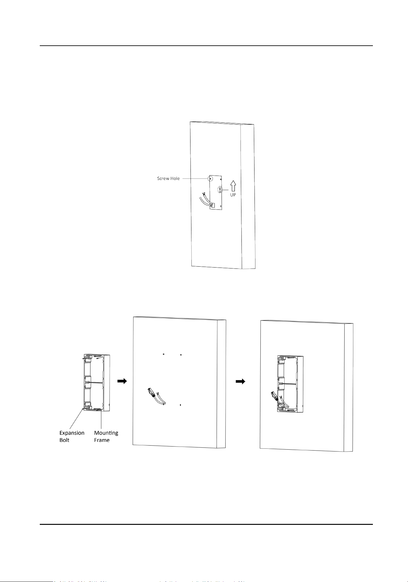
3.2.1 One-Module Surface Mounng
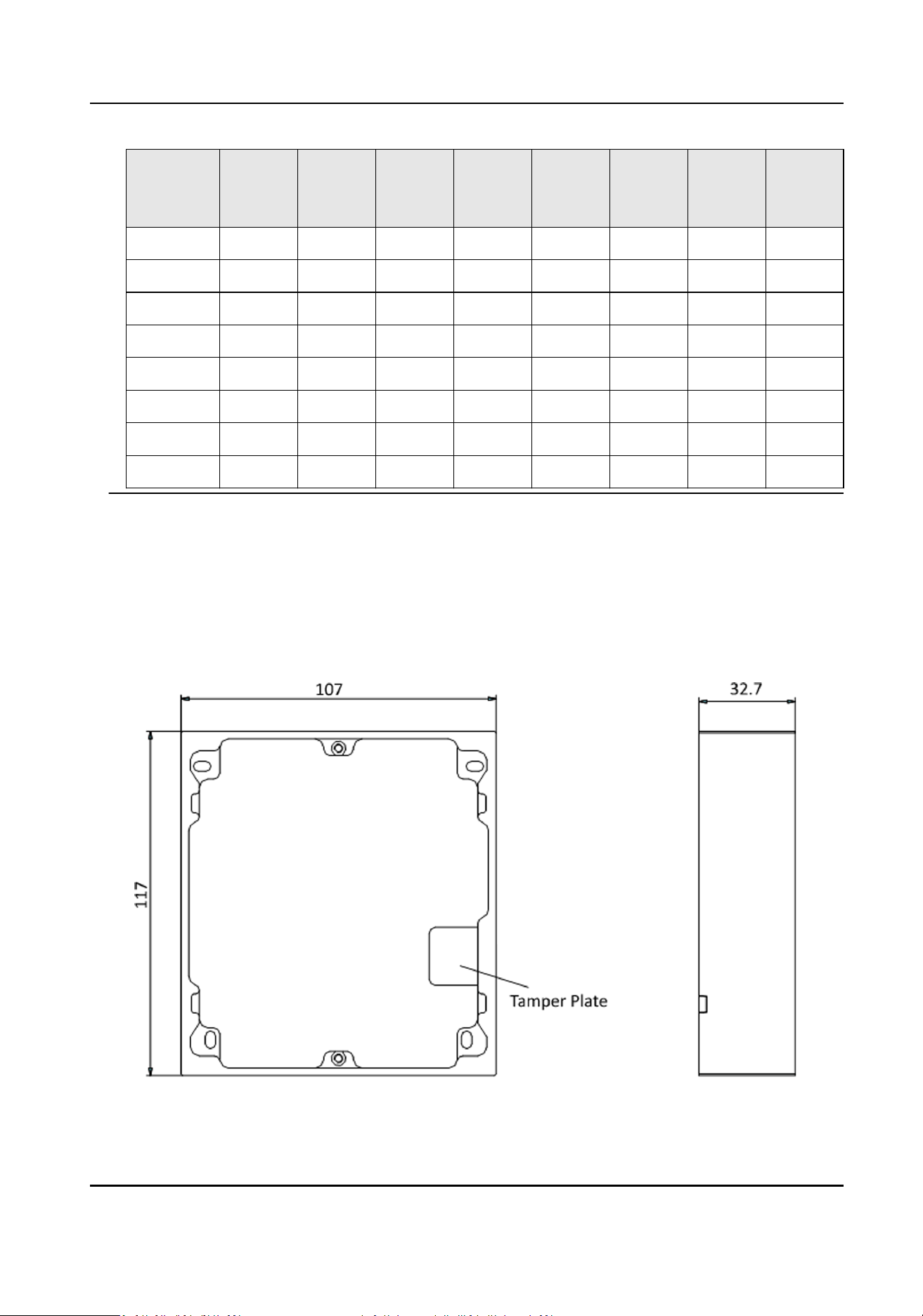
Before You Start
Figure 3-2 Mounng Frame
Module Door Staon User Manual
20
Note
●
The dimension of one module mounng frame (W × H × D) is: 117 mm × 107 mm × 32.7 mm.
●
The dimensions above are for reference only. The actual size can be slightly dierent from the
theorecal dimension.
Steps
1.
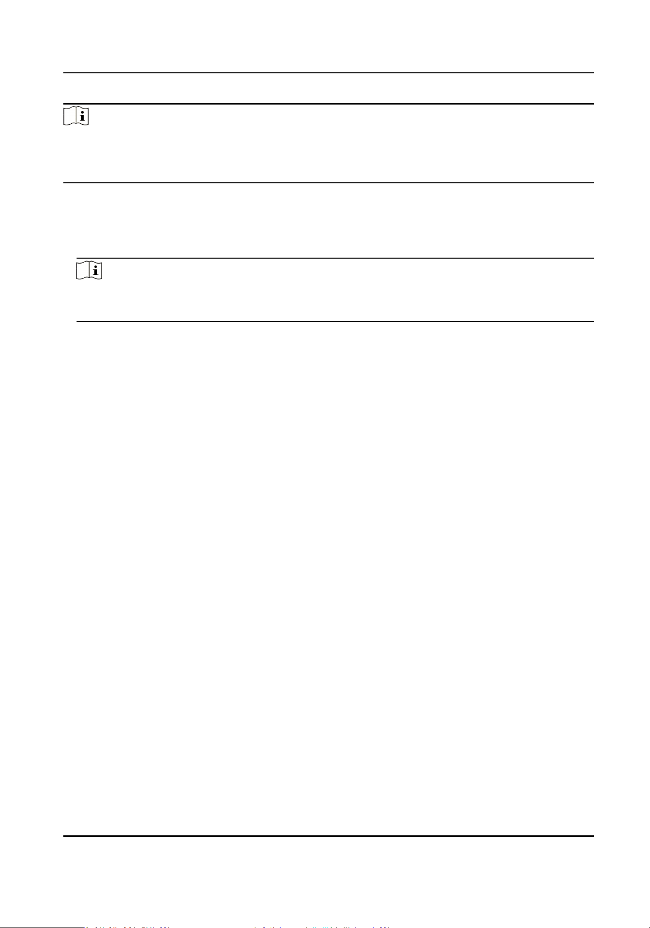
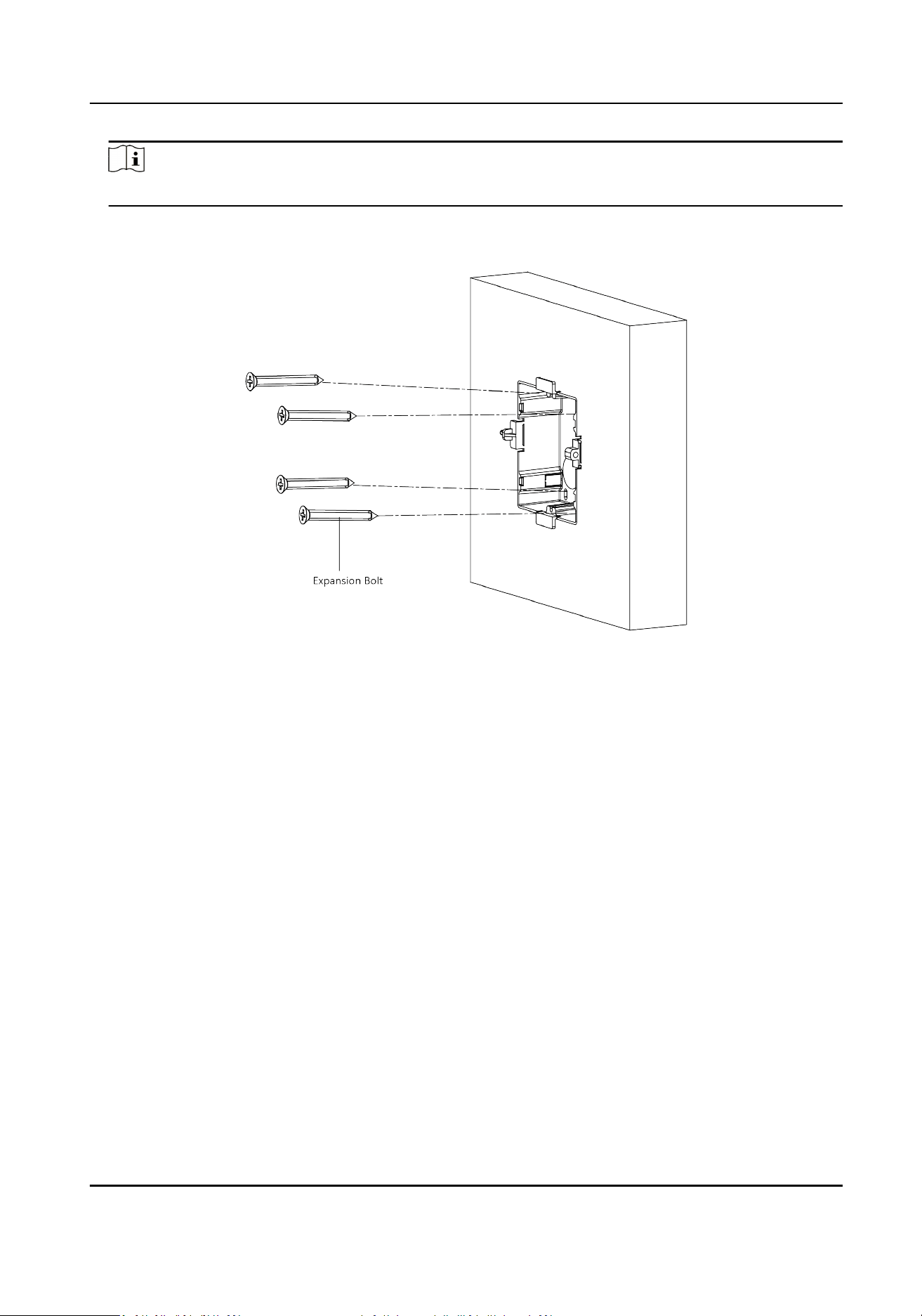
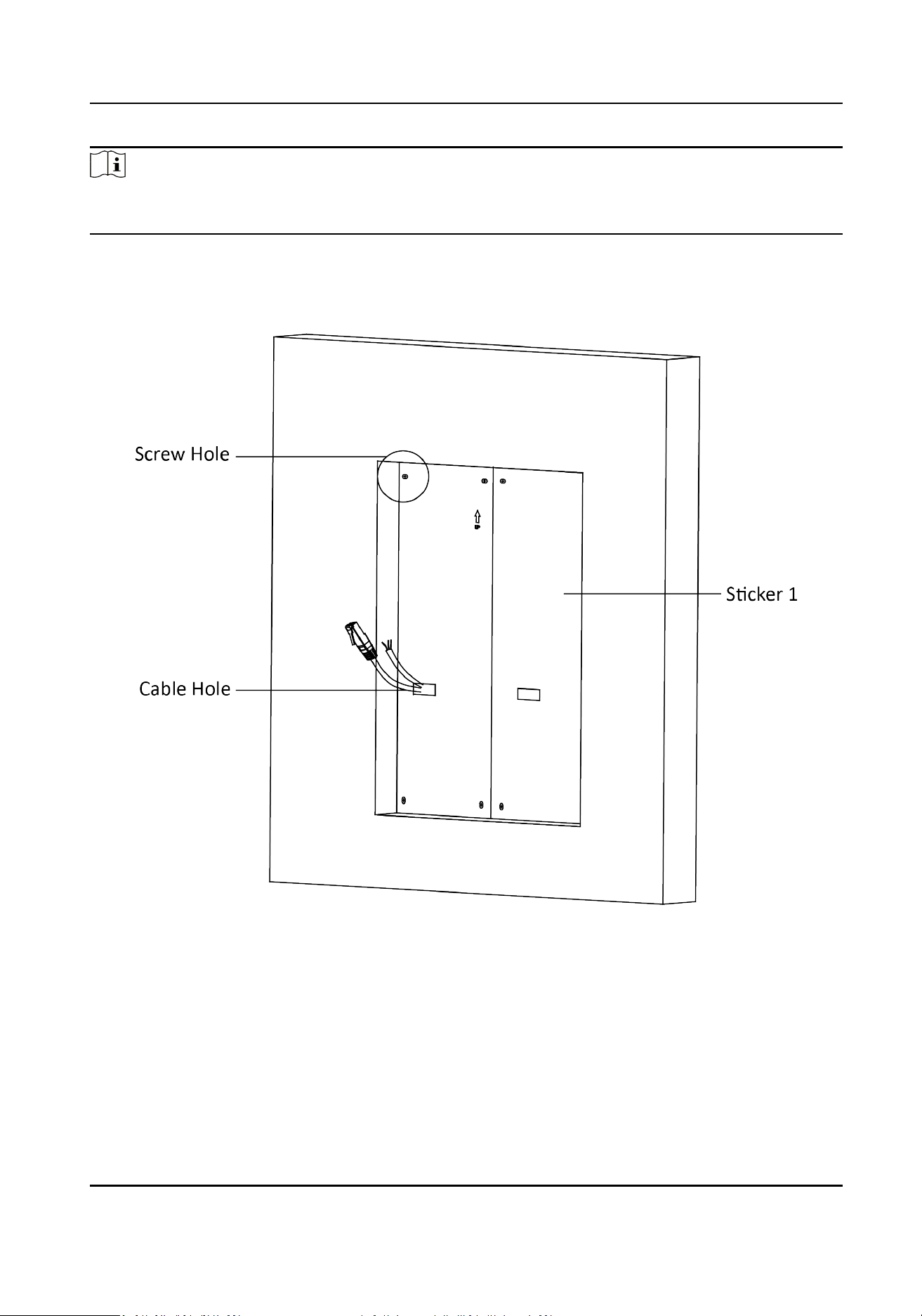
Paste the installaon Scker 1 onto the wall. Make sure the scker is placed horizontally via
measuring with the gradienter.
2.
Drill 4 holes according to the screw holes on the
scker.
Note
●
The suggested size of hole is 6 (diameter) × 25 (depth) mm.
●
The suggested length of cables le outside is 100 mm.
Module Door Staon User Manual
21
Figure 3-3 Drill Screw Holes
3.
Remove the stricker and insert the expansion sleeves into the screw holes.
4.
Fix the
mounng frame onto the wall with 4 expansion bolts.
Module Door Staon User Manual
22
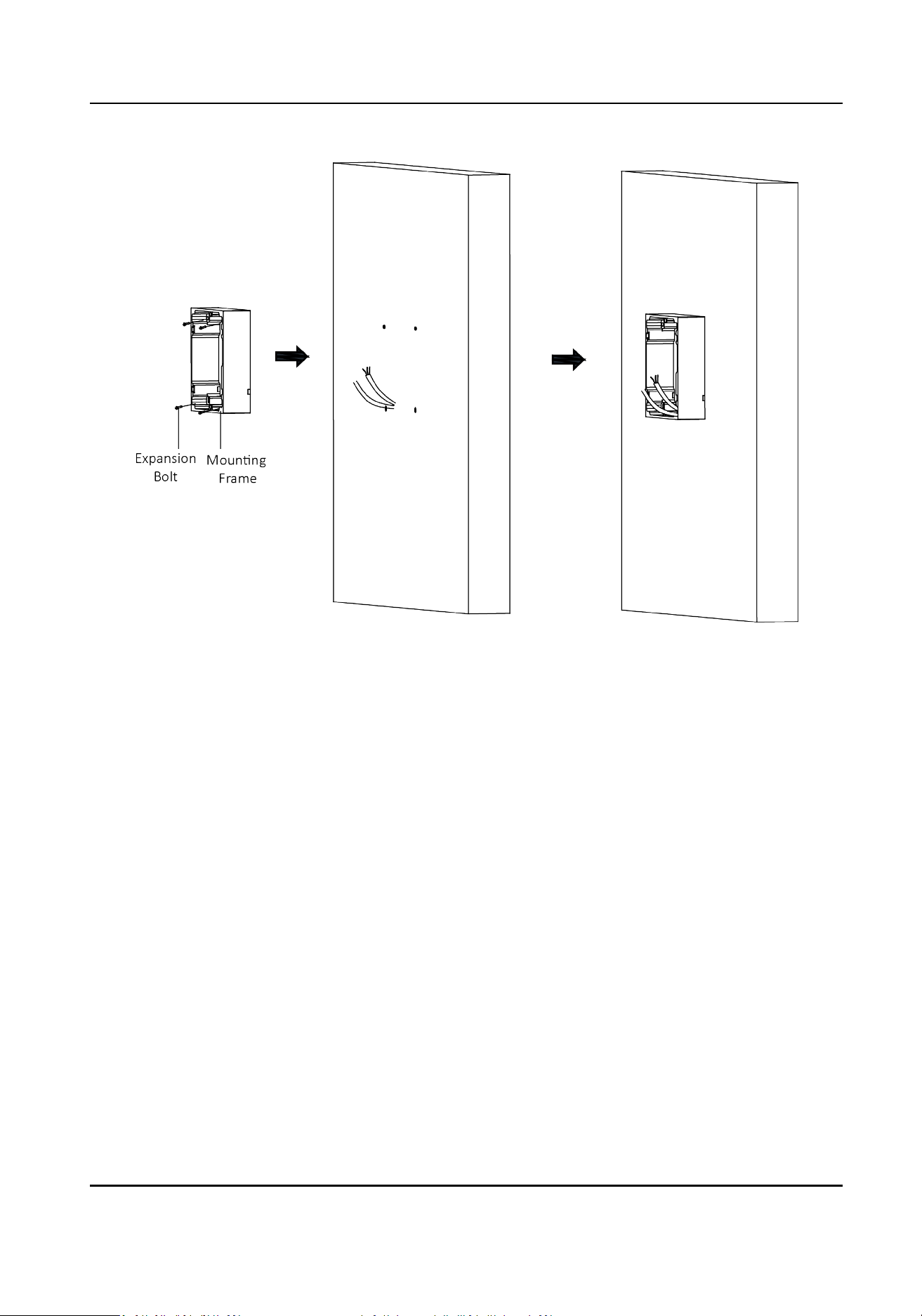
Figure 3-4 Fix the Mounng Frame
5.
Connect the cables to the corresponding interfaces of the main unit and insert the main unit
into the frame.
Module Door Staon User Manual
23
Figure 3-5 Insert the Main Unit
6.
Fix the cover onto the frame.
Module Door Staon User Manual
24
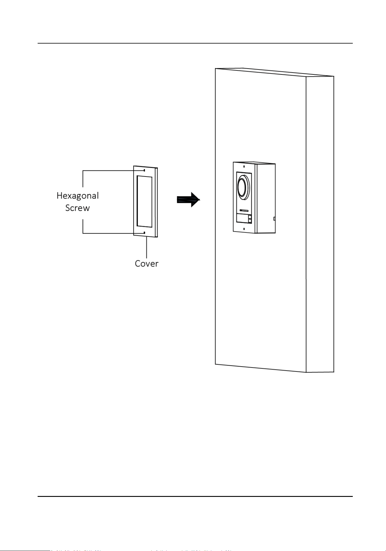
Figure 3-6 Fix the Cover
Module Door Staon User Manual
25
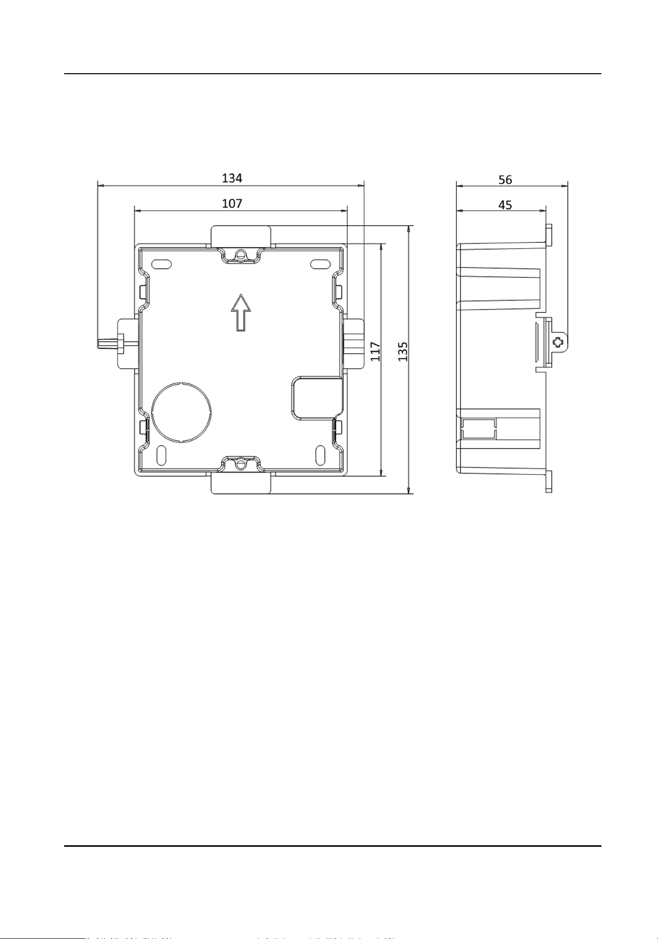
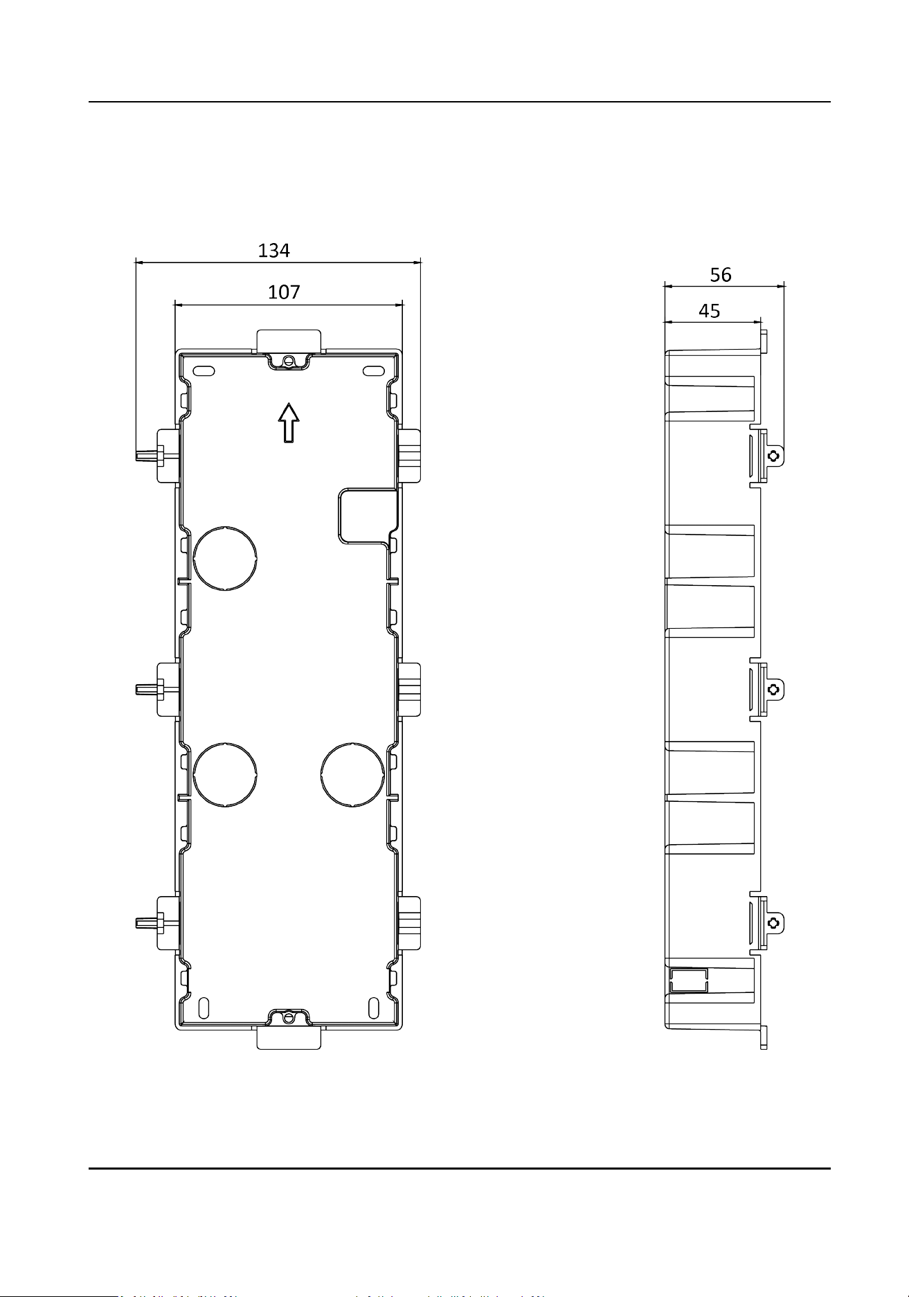
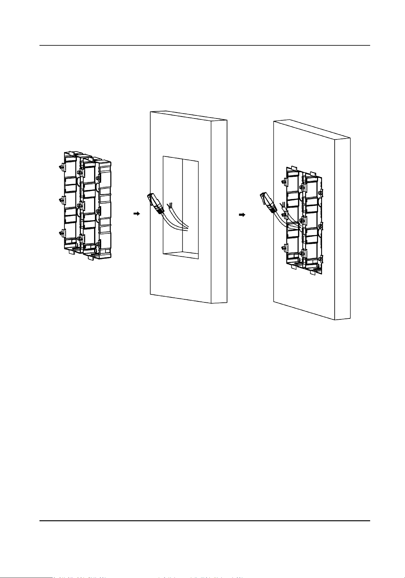
3.2.2 One-Module Flush Mounng
Before You Start
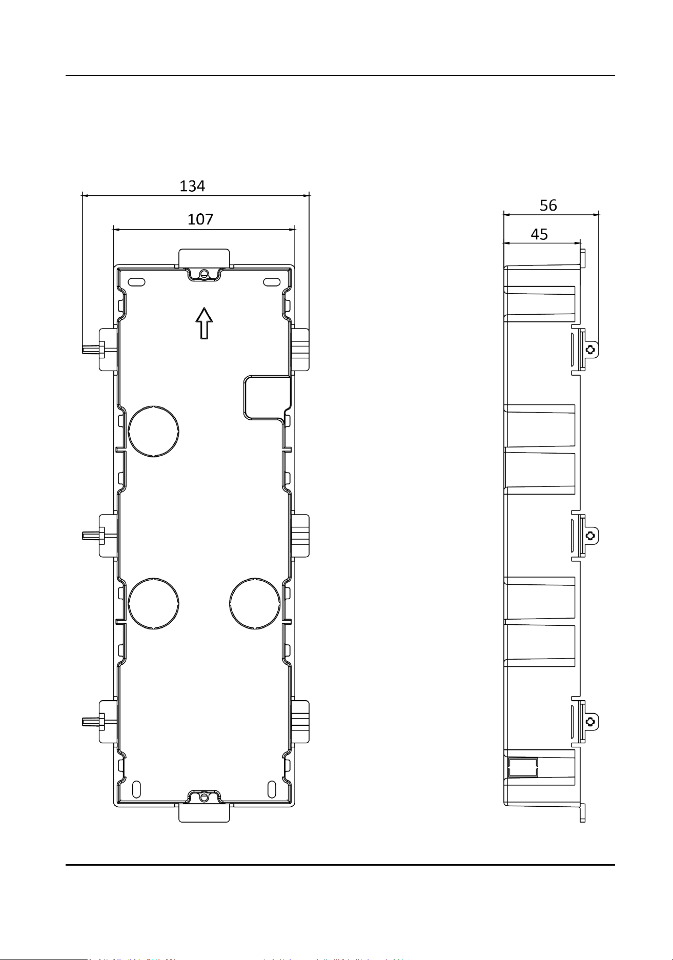
Figure 3-7 Front and Side View of the Gang Box
Module Door Staon User Manual
26
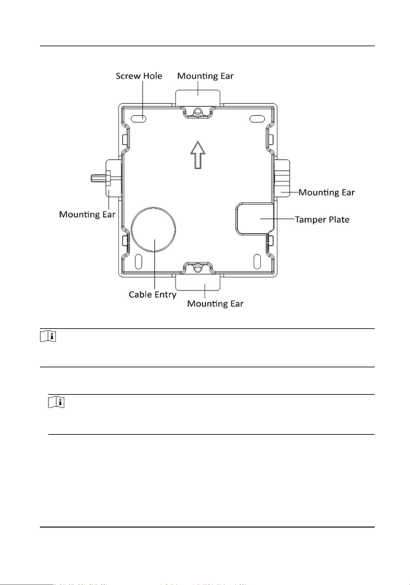
Figure 3-8 Gang Box
Note
The dimension of one-module gang box is: 115 (W) × 134 (H) × 56 (D) mm. The dimension is for
reference only.
Steps
1.
Drill an
installaon hole, and pull the cables out.
Note
●
The suggested dimension of installaon hole is 118 (W) × 108 (H) × 45.5 (D) mm.
●
The suggested length of cables le outside is 100 mm.
Module Door Staon User Manual
27
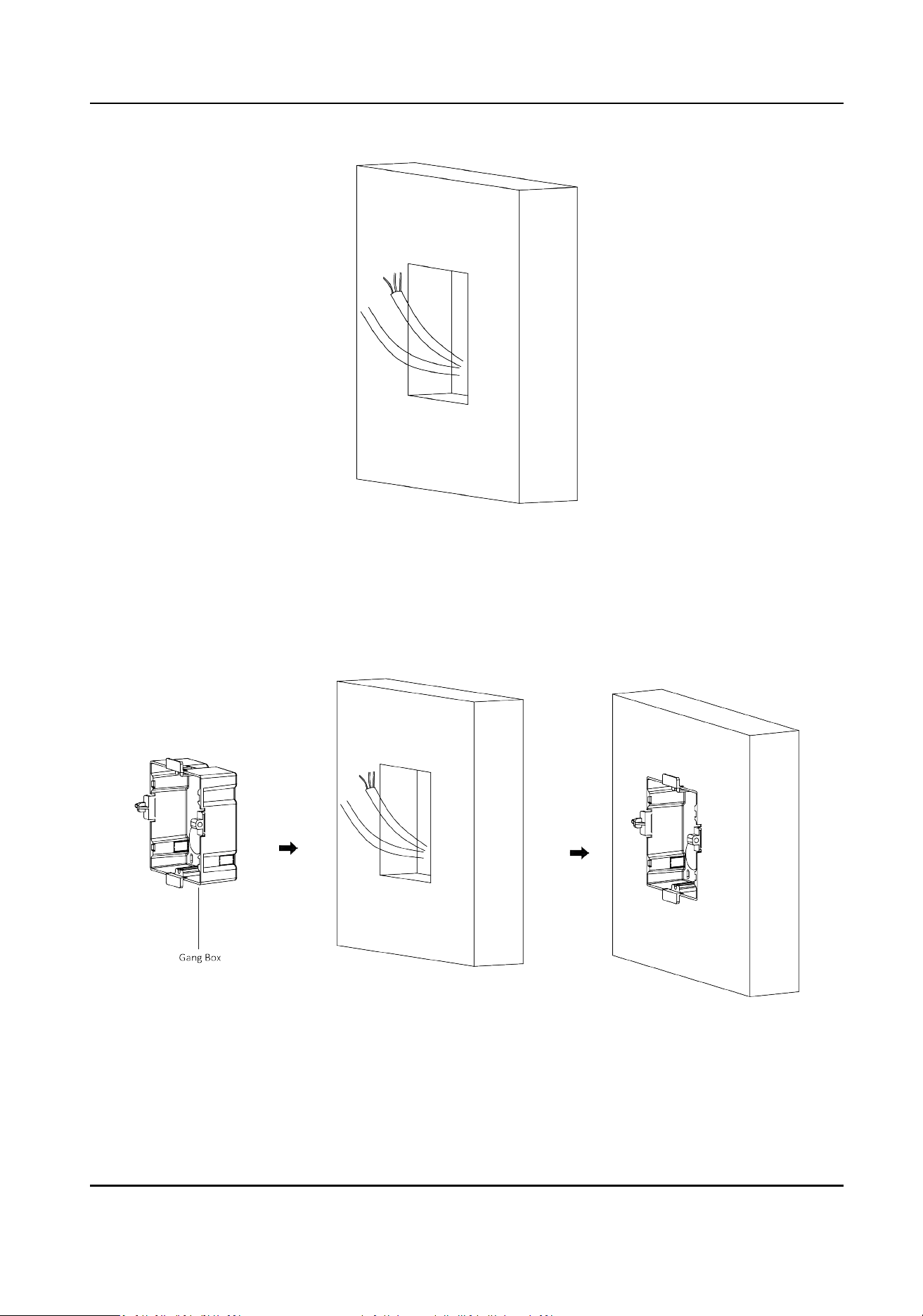
Figure 3-9 Drill Installaon Hole
2.
Remove the
plasc sheet of the cable entry.
3.
Mark the gang box screw holes on the wall.
1) Route the cables through the gang box hole.
2) Insert the gang box into the
installaon hole.
3) Mark the gang box screw holes' posion with a marker, and take out the gang box.
Figure 3-10 Mark the Screw Holes
4.
Drill 4 holes according to marks on the wall, and insert the expansion sleeves into the screw
holes.
Module Door Staon User Manual
28
Note
The suggested size of the hole is 6 (diameter) × 45 (depth) mm.
5.
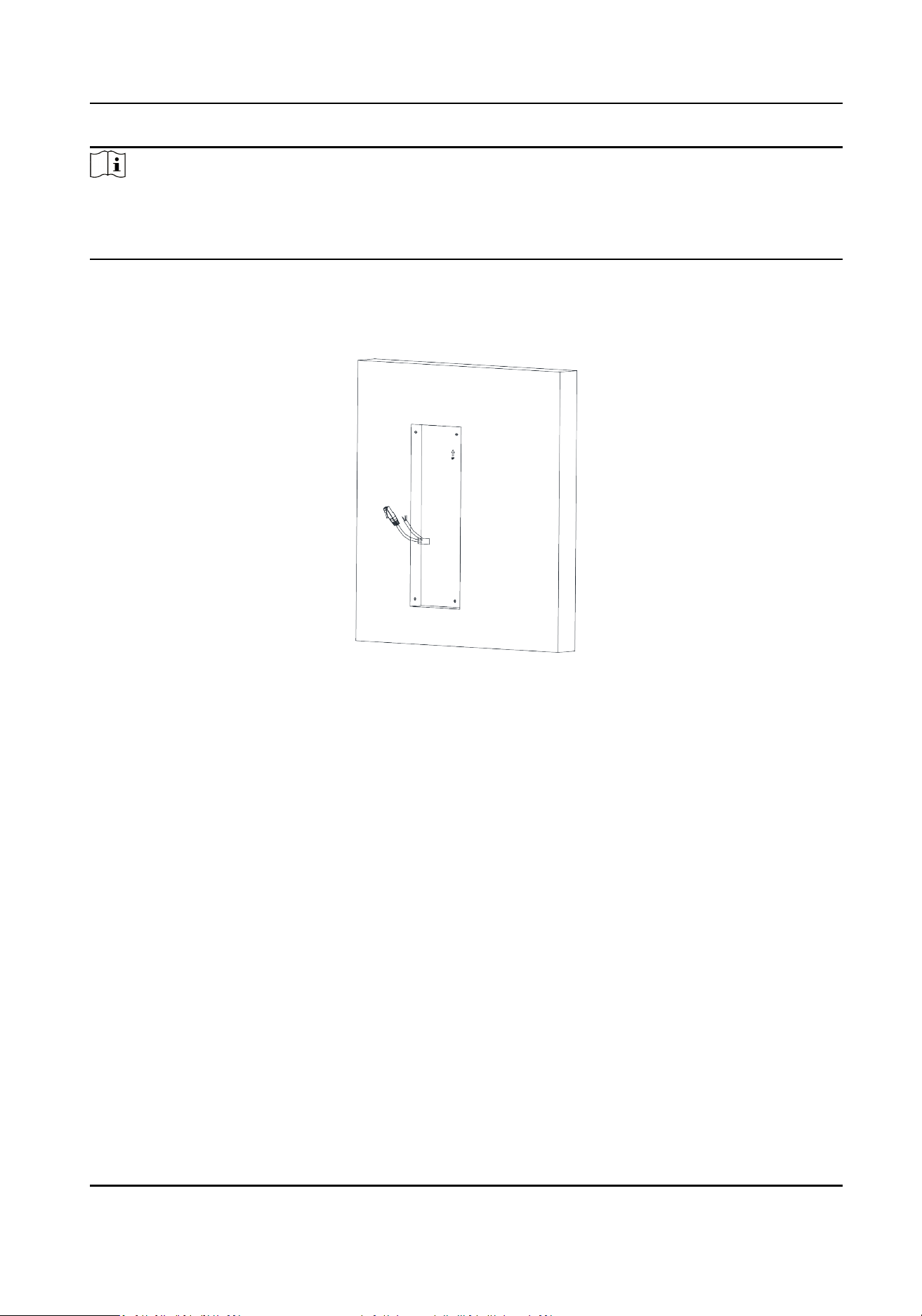
Route the cables through the gang box hole. Insert the gang box into the installaon hole. Fix
the gang box with 4 expansion bolts.
Figure 3-11 Fix the Gang Box
6.
Fill the gap between the gang box and the wall with concrete. Remove the 4 mounng ears with
tool aer concrete is dry.
Module Door Staon User Manual
29
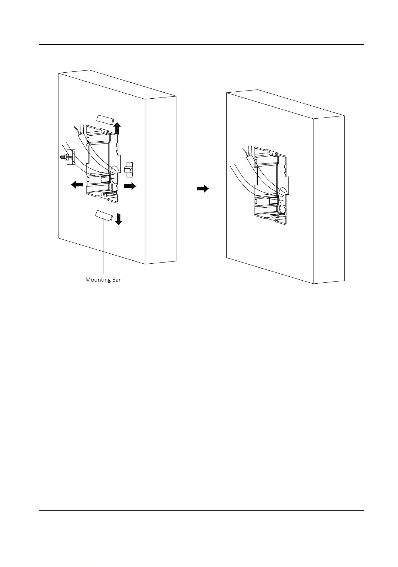
Figure 3-12 Remove the Mounng Ears
7.
Connect the cables to the corresponding interfaces of the main unit and insert the unit into the
gang box.
Module Door Staon User Manual
30
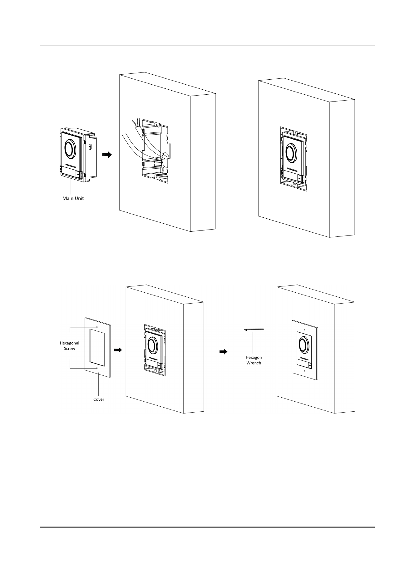
Figure 3-13 Insert the Main Unit
8.
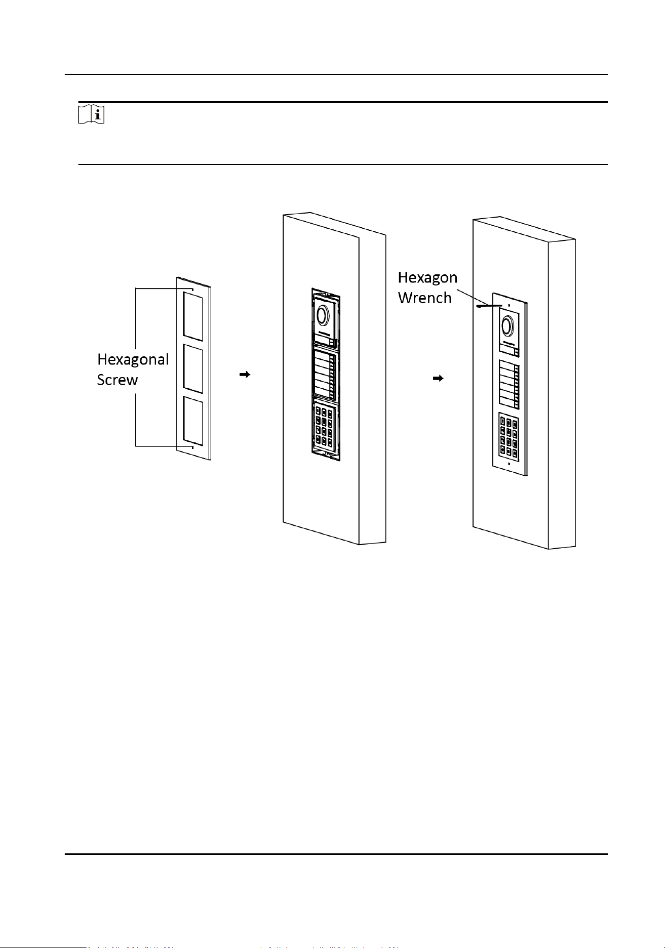
Fix the cover and the main unit with 2 socket head cap screws by using a hexagon wrench
(supplied).
Figure 3-14 Fix the Cover
Module Door Staon User Manual
31
3.3 Two-Module Installaon
3.3.1 Two-Module Surface Mounng
Before You Start
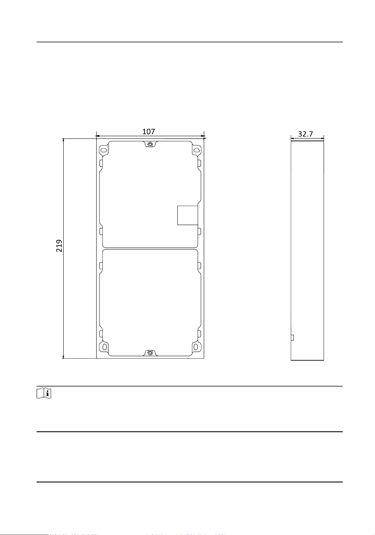
Figure 3-15 Mounng Frame
Note
●
The dimension of two-module mounng frame (W × H × D) is: 219 mm × 107 mm × 32.7 mm.
●
The dimensions above are for reference only. The actual size can be slightly dierent from the
theorecal dimension.
Module Door Staon User Manual
32
Steps
1.
Paste the installaon Scker 1 onto the wall. Make sure the scker is placed horizontally via
measuring with the gradienter.
2.
Drill 4 holes according to the screw holes on the
scker. The suggested size of hole is 6
(diameter) × 25 (depth) mm. The suggested length of cables
le outside is 270 mm.
Figure 3-16 Drill Screw Holes
3.
Remove the scker and insert the expansion sleeves into the screw holes.
4.
Fix the mounng frame onto the wall with 4 expansion bolts.
Figure 3-17 Fix the Mounng Frame
5.
Thread the module-connecng line across the thread hole of the frame. Pass the main unit
connecng lines across the thread hole to the upper grid.
Module Door Staon User Manual
33
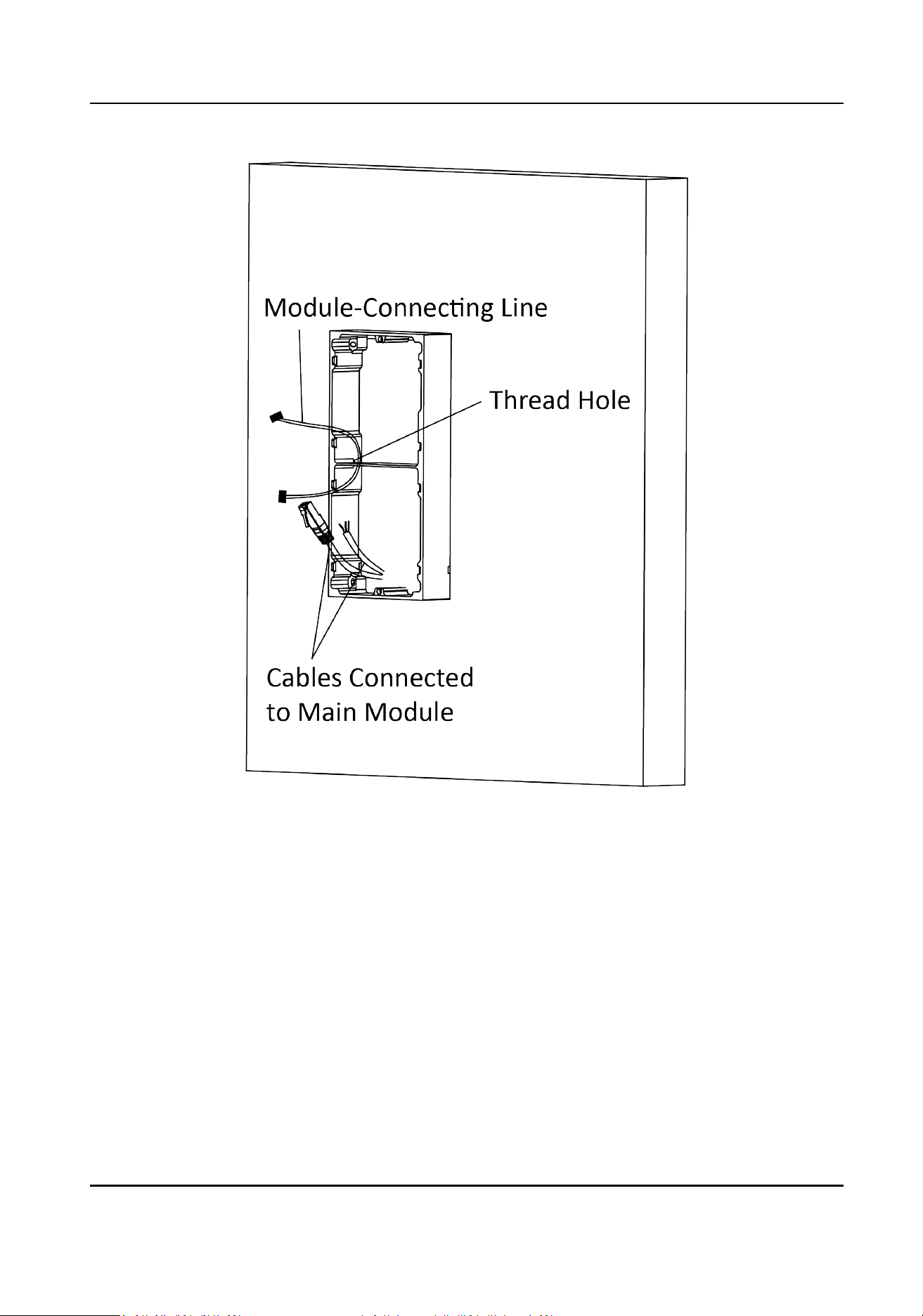
Figure 3-18 Placement of Lines
6.
Connect the cables.
1) Connect the lines and
module-connecng line to the corresponding interfaces of the main
unit, then place the main unit into the upper grid.
2) Connect the other end of the
module-connecng line to the input interface of the sub
module.
3) Organize the cable with cable
e in the package. The suggested cable connecon picture as
shown below.
Module Door Staon User Manual
34
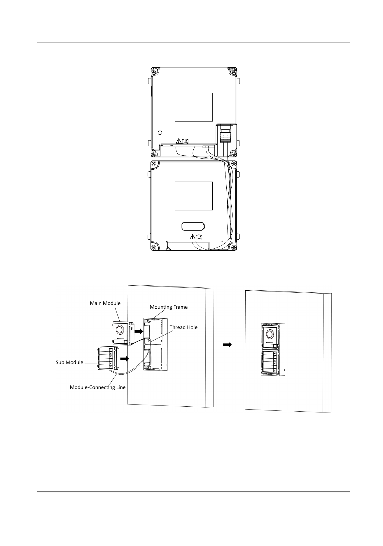
Figure 3-19 Line Connecon Eect Picture
7.
Insert the modules into the frame aer wiring. The main unit must be placed in the top grid.
Figure 3-20 Insert the Modules
8.
Use the hexagon wrench in the package to x the cover onto the frame.
Module Door Staon User Manual
35
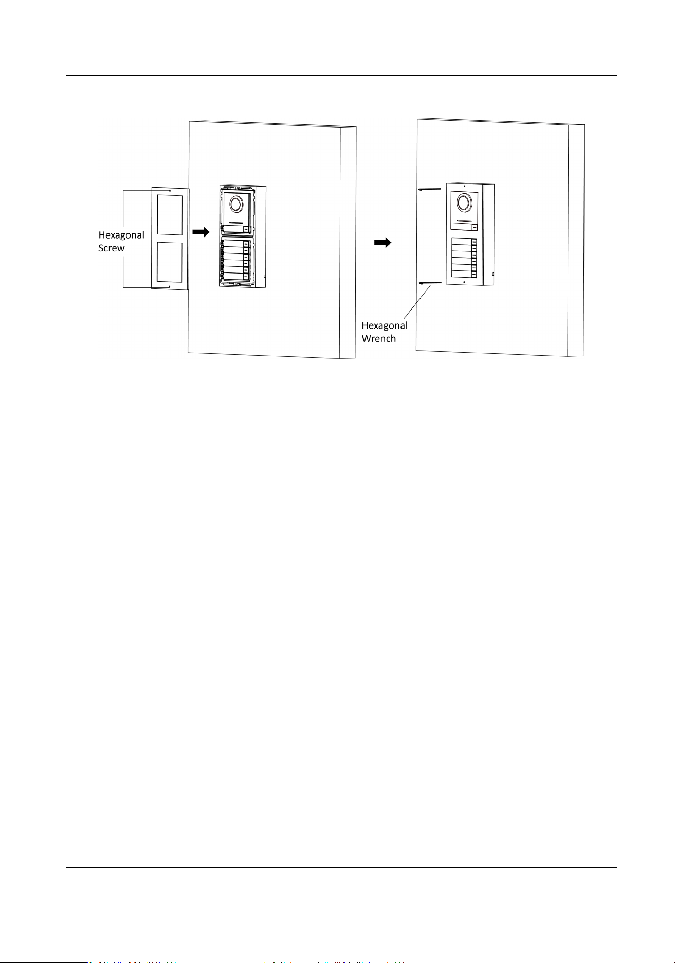
Figure 3-21 Fix the Cover
Module Door Staon User Manual
36
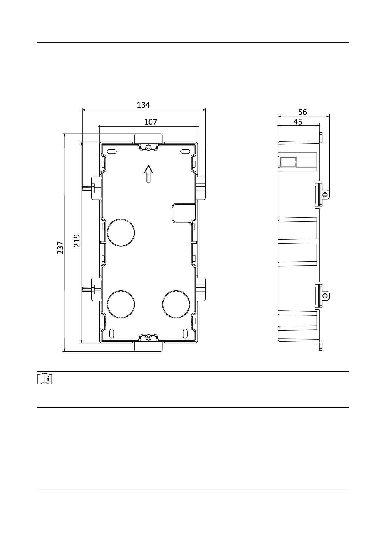
3.3.2 Two-Module Flush Mounng
Before You Start
Figure 3-22 Gang Box
Note
The dimension of two-module gang box is: 237 (W) × 134 (H) × 56 (D) mm. The dimension is for
reference only.
Steps
1.
Drill the installaon hole, and pull the cable out.
Module Door Staon User Manual
37
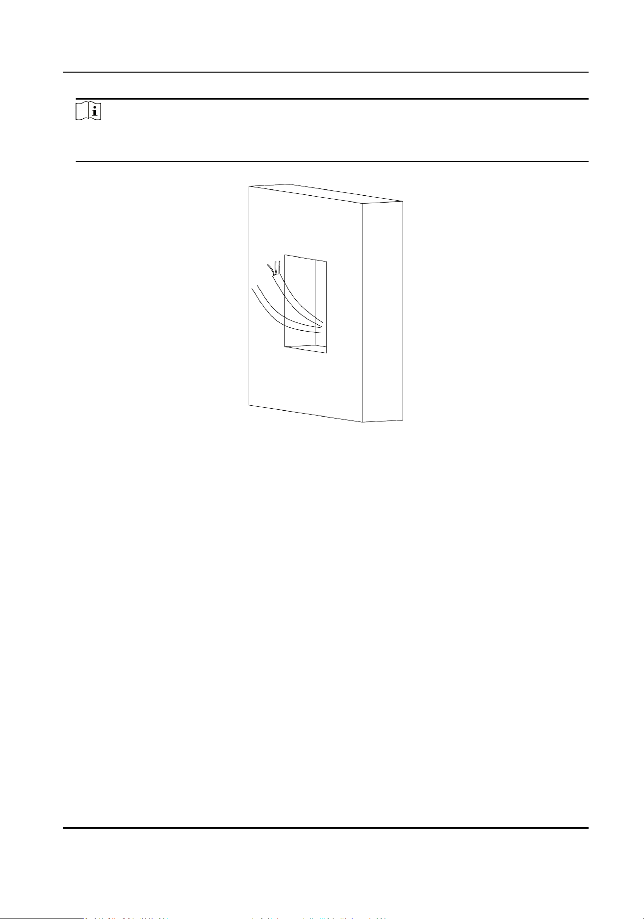
Note
●
The suggested dimension of installaon hole is 220 (W) × 108 (H) × 45.5 (D) mm.
●
The suggested length of cables le outside is 270 mm.
Figure 3-23 Drill the Installaon Hole
2.
Select a cable entry and remove the plasc sheet.
3.
Mark the gang box screw holes on the hole.
1) Routs the cables through the gang box hole.
2) Insert the gang box into the
installaon hole.
3) Mark the gang box screw holes'
posion with a marker, and take out the gang box.
Module Door Staon User Manual
38
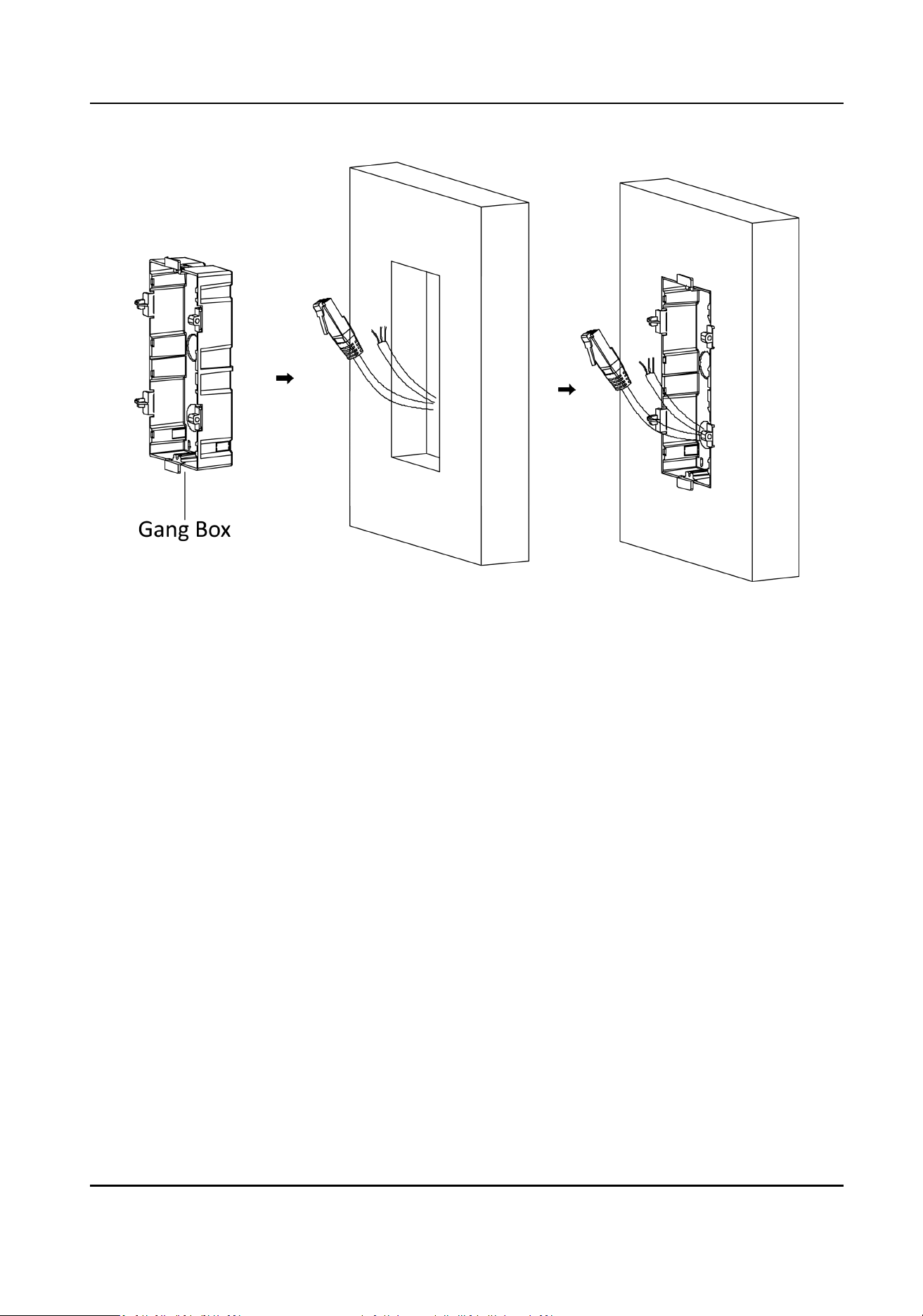
Figure 3-24 Mark the Screw Holes
4.
Drill 4 holes according to the marks on the wall, and insert the expansion sleeves into the screw
holes. The suggested size of hole is 6 (diameter) × 45 (depth) mm.
5.
Fix the gang box with 4 expansion bolts.
Module Door Staon User Manual
39
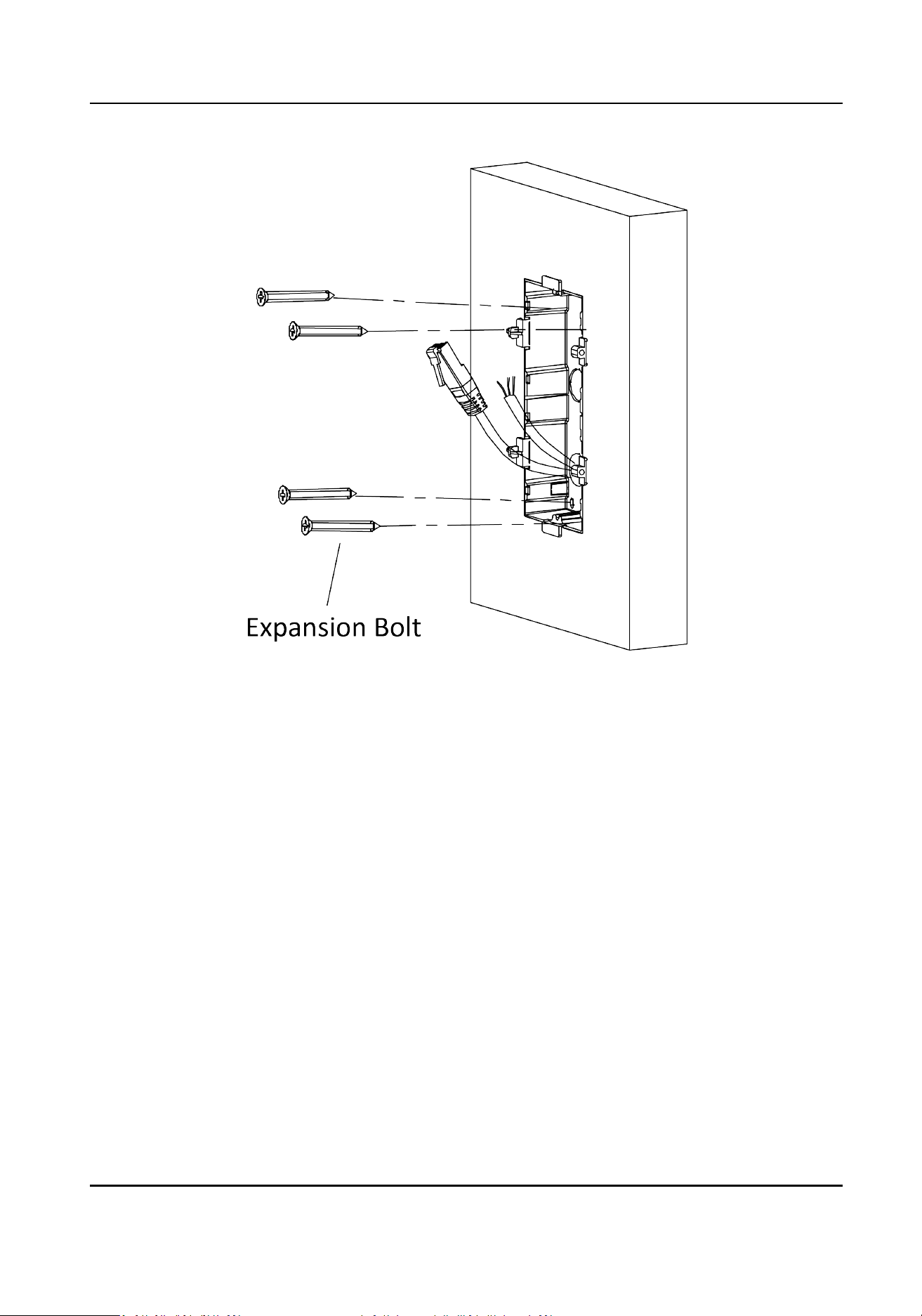
Figure 3-25 Fix the Gang Box
6.
Fill the gap between the gang box and the wall with concrete. Remove the mounng ears with
tool aer concrete is dry.
Module Door Staon User Manual
40
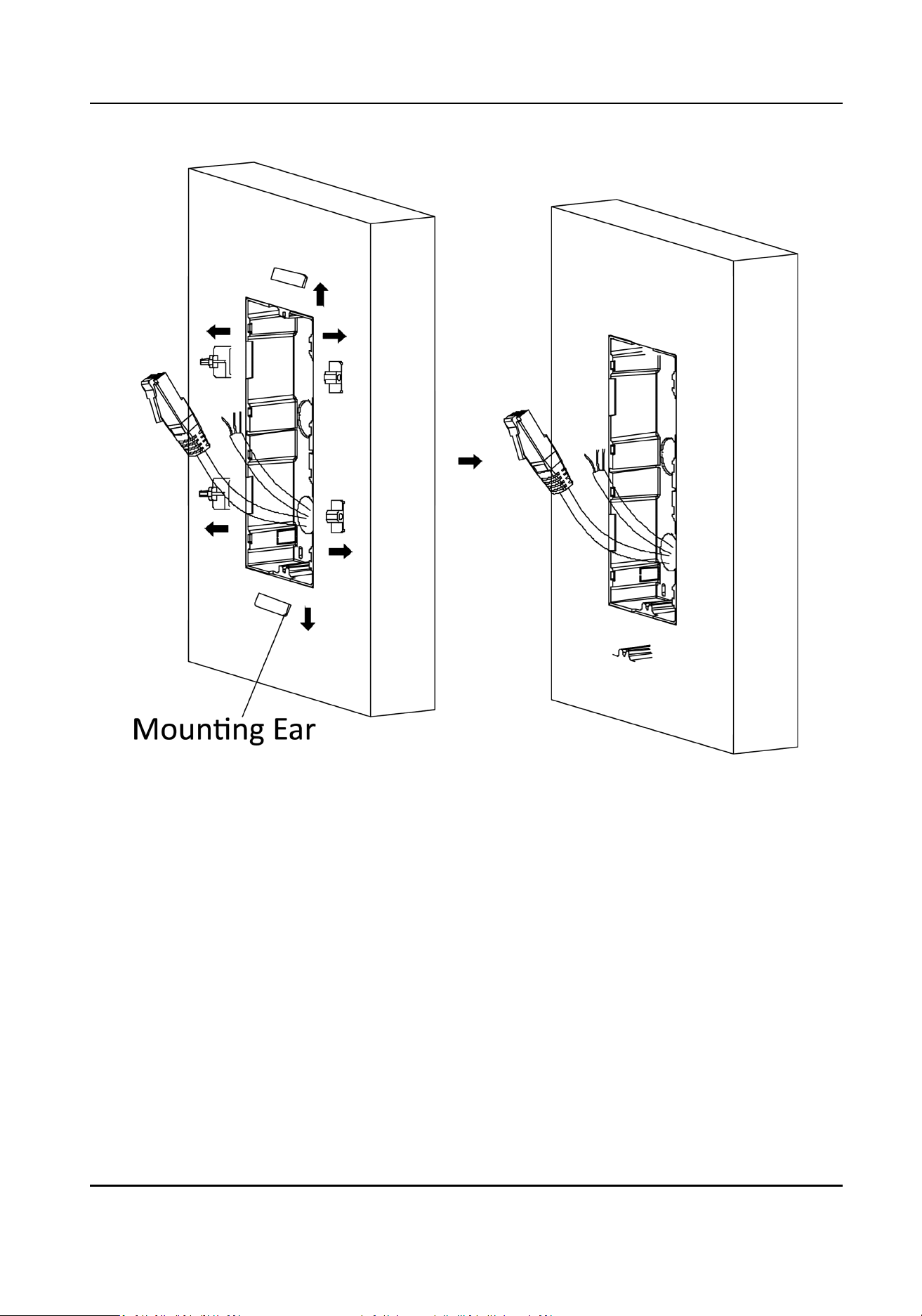
Figure 3-26 Remove the Mounng Ears
7.
Connect cables and insert the modules.
1) Connect Cable 1 and one end of Cable 2 to the corresponding interfaces of the main unit,
then insert the main unit into the upper grid.
2) Connect the other end of Cable 2 to the input interface of the sub module. Insert it into the
lower grid.
Module Door Staon User Manual
41
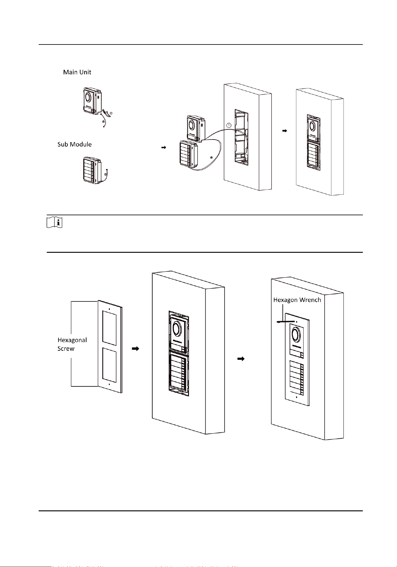
Figure 3-27 Connect Cables and Insert the Modules
Note
Cable 1 refers to the cables pulled out from the wall that connected to the main unit. Cable 2
refers to the module-connecng line in the accessory package.
8.
Fix the cover with 2 socket head cap screws by using a hexagon wrench (supplied).
Figure 3-28 Fix the Cover
Module Door Staon User Manual
42
3.4 Three-Module Installaon
3.4.1 Three-Module Surface Installaon
Before You Start
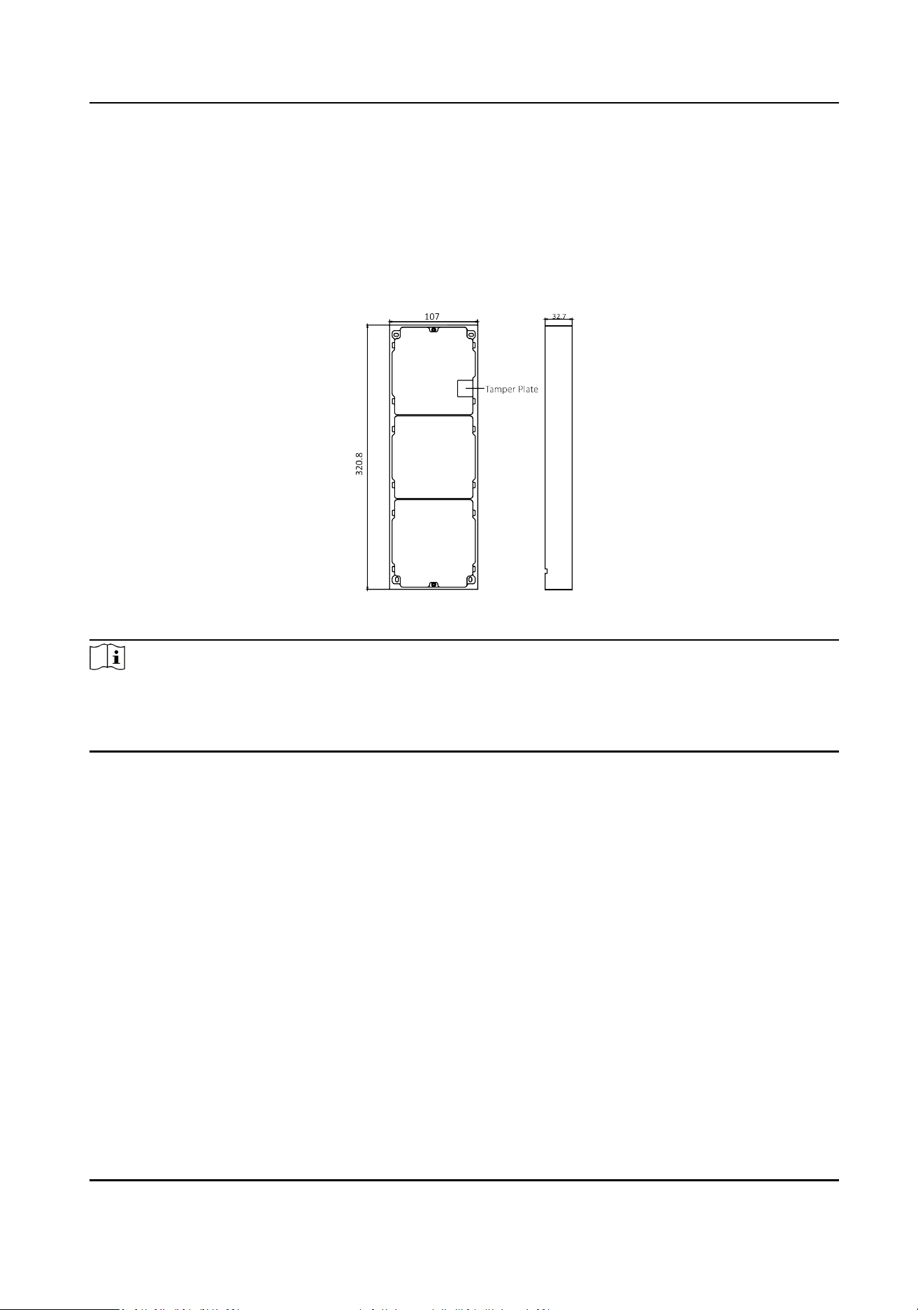
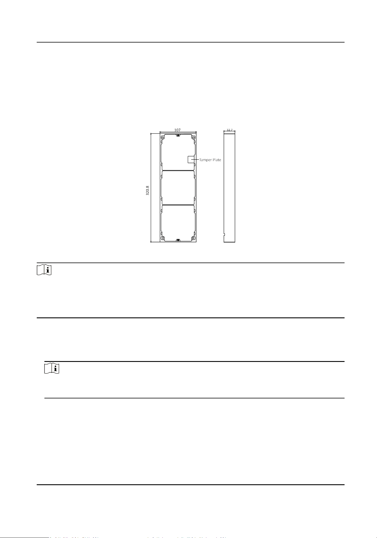
Figure 3-29 Mounng Frame
Note
●
The dimension of two-module mounng frame (W × H × D) is: 320.8 mm × 107 mm × 32.7 mm.
●
The dimensions above are for reference only. The actual size can be slightly dierent from the
theorecal dimension.
Steps
1.
Paste the
installaon scker 1 onto the wall. Make sure the scker is placed horizontally via
measuring with the gradienter.
2.
Drill 4 holes according to the screw holes on the
scker.The suggested size of hole is 6 (diameter)
× 25 (depth) mm. The suggested length of cables le outside is 270 mm.
Module Door Staon User Manual
43
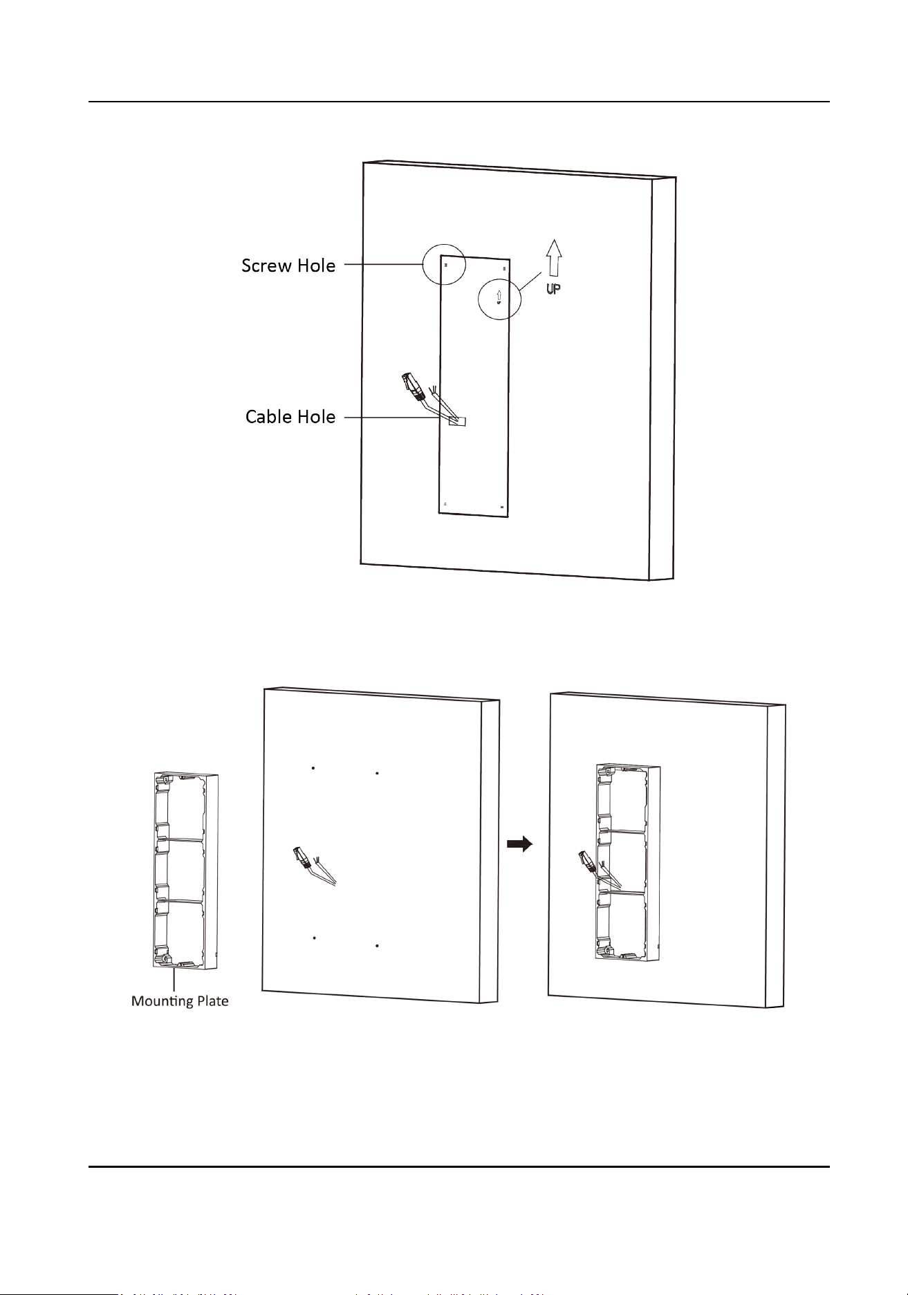
Figure 3-30 Drill Screw Holes
3.
Remove the scker and insert the expansion sleeves into the screw holes.
4.
Fix the
mounng frame onto the wall with 4 expansion bolts.
Figure 3-31 Fix the Mounng Frame
Module Door Staon User Manual
44
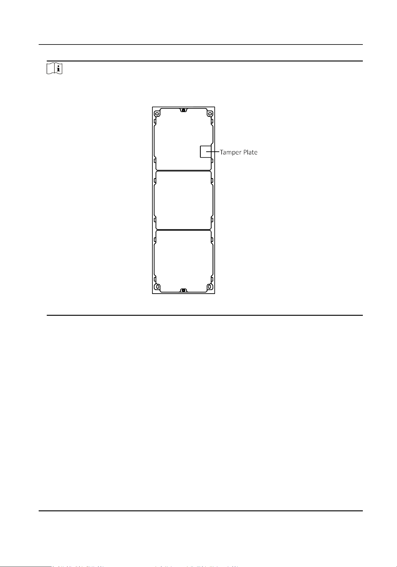
Note
The mounng frame should be placed exactly as shown below for this step. The tamper plate
should be at the low right of the rst grid.
Figure 3-32 Mounng Frame
5.
Thread the module-connecng line across the thread holes of the frame. Pass the main unit
connecng line across the thread hole to the top grid.
Module Door Staon User Manual
45
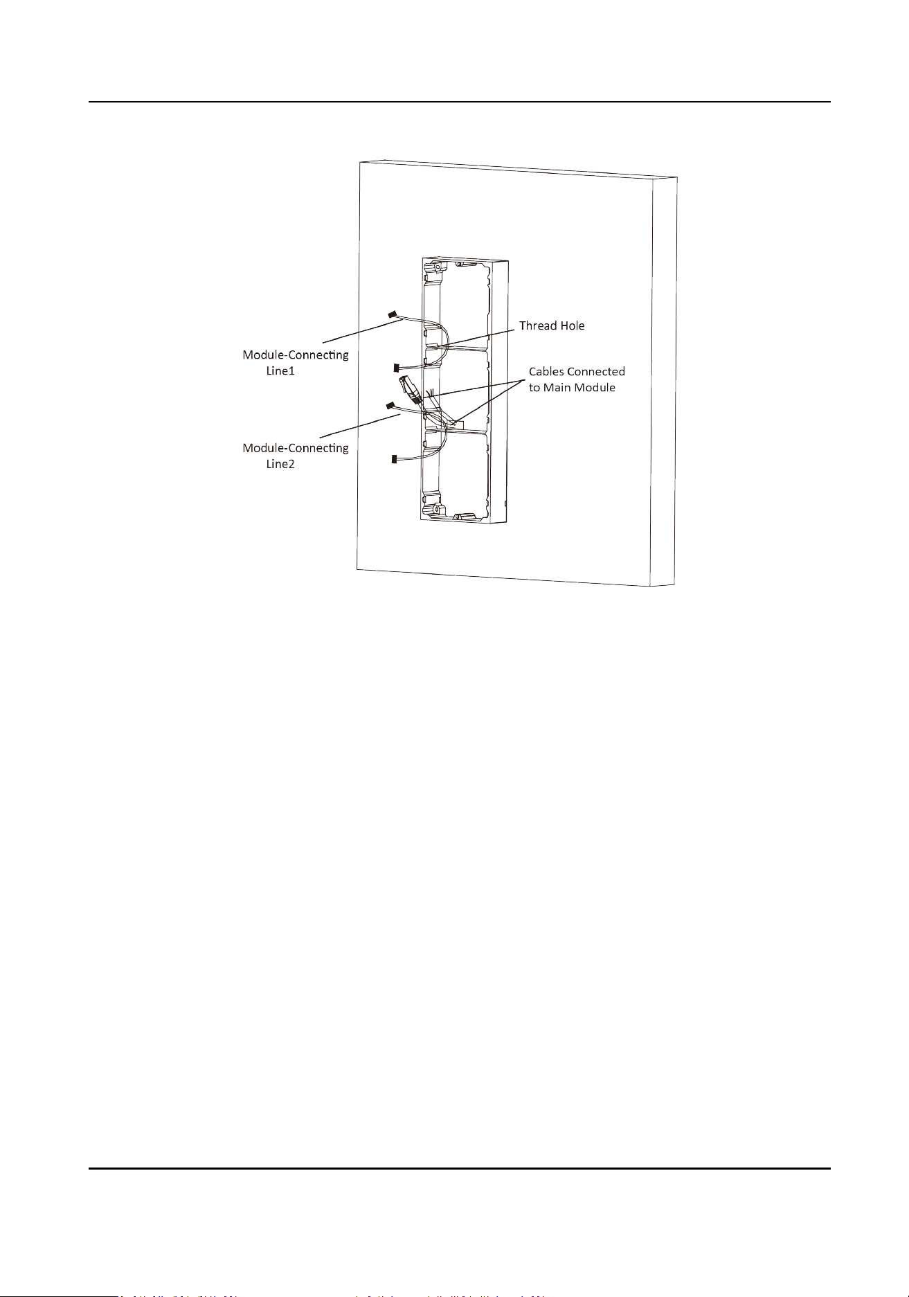
Figure 3-33 Placement of Lines
6.
Connect the cables.
1) Connect the lines and
module-connecng line 1 to the corresponding interfaces of the main
unit, then place the main unit into the upper grid.
2) Connect the other end of the
module-connecng line 1 to the input interface of the sub
module. Connect two sub modules via module-connecng line 2.
3) Organize the cables with cable e in the package. The suggested cable connecon picture as
shown below.
Module Door Staon User Manual
46
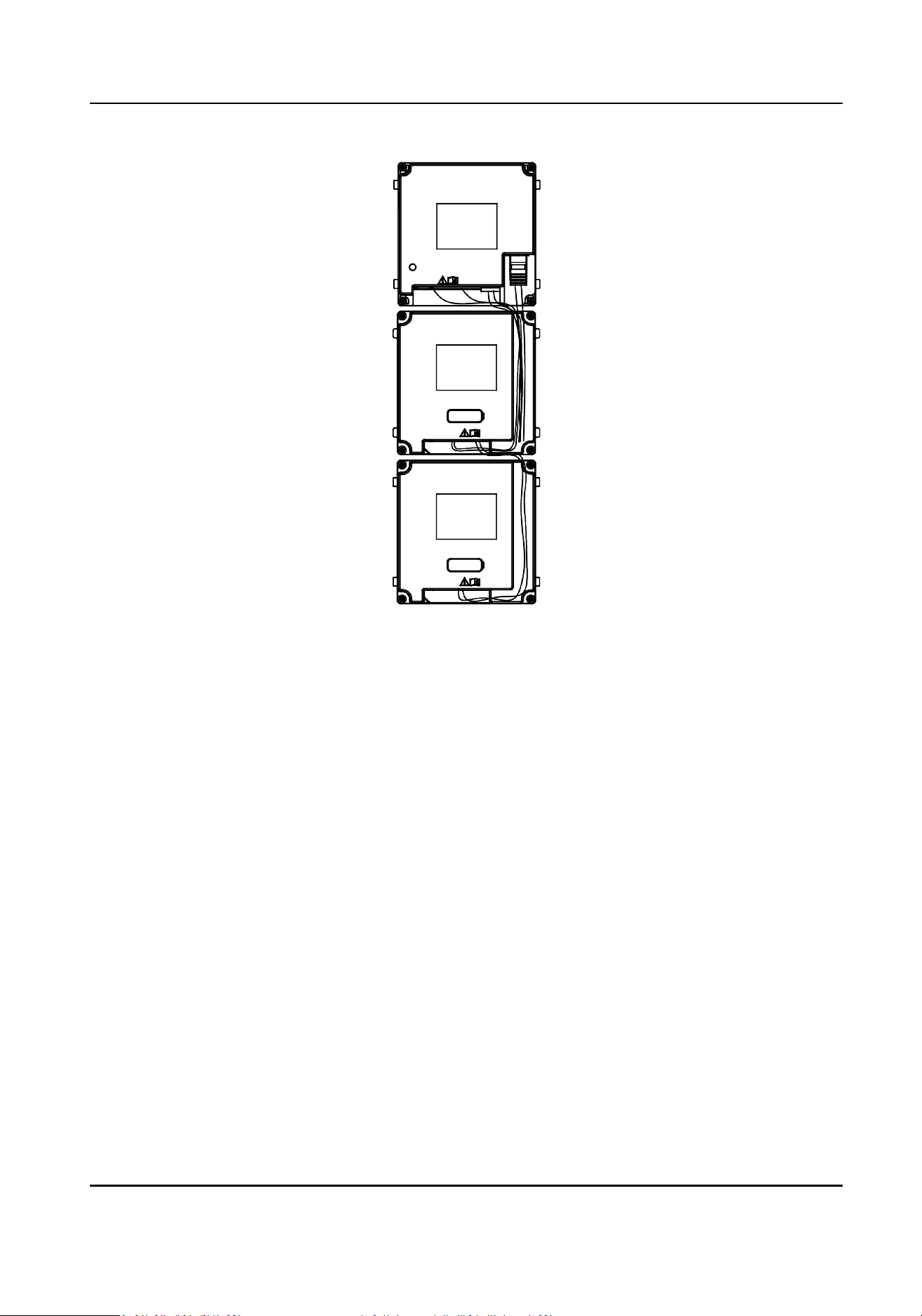
Figure 3-34 Line Connecon Eect Picture
7.
Insert the modules into the frame aer wiring. The main unit must be placed in the top grid.
Module Door Staon User Manual
47
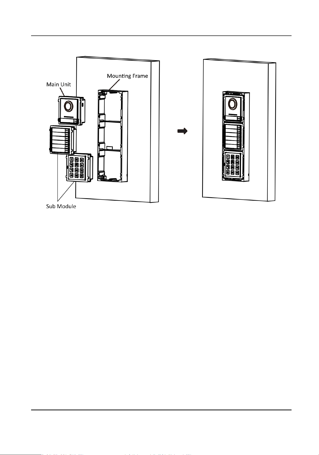
Figure 3-35 Insert the Modules into the Frame
8.
Use the hexagon wrench in the package to x the cover onto the frame.
Module Door Staon User Manual
48
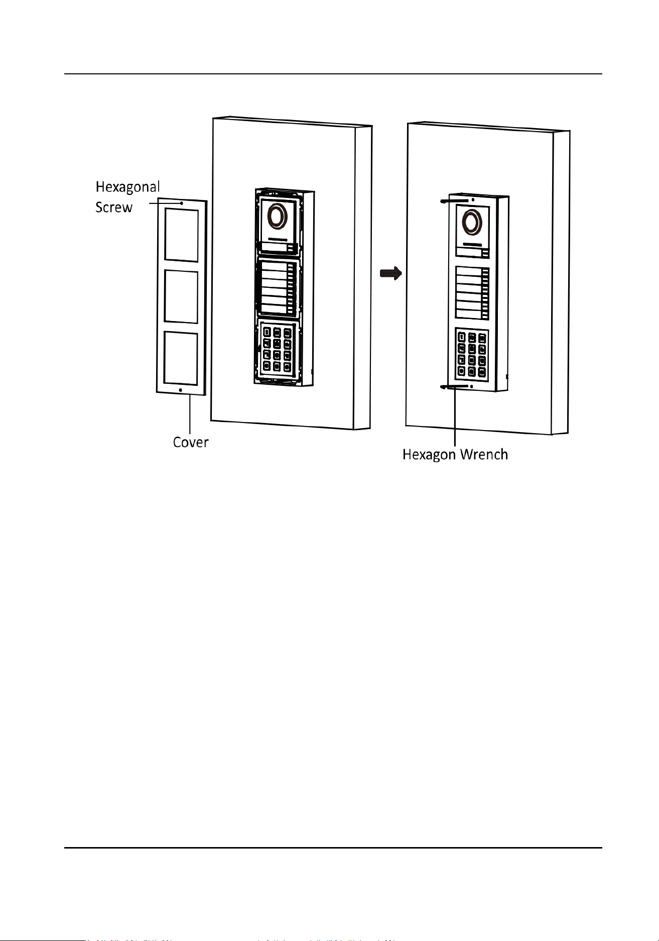
Figure 3-36 Fix the Cover
Module Door Staon User Manual
49
3.4.2 Three-Module Flush Mounng
Before You Start
Figure 3-37 Gang Box
Module Door Staon User Manual
50
Note
●
The dimension of one-module gang box is: 338.8(W)×134(H)×56(D) mm.
●
The dimensions above are for reference only. The actual size can be slightly dierent from the
theorecal dimension.
Steps
1.
Cave the installaon hole, and pull the cable out.The suggested dimension of installaon hole is
321.8(W)×108(H)×45.5(D) mm. The suggested length of cables
le outside is 270 mm.
Figure 3-38 Cave the Installaon Hole
2.
Select a cable entry and remove the plasc sheet.
3.
Mark the gang box screw holes on the wall.
1) Route the cables through the gang box hole.
2) Insert the gang box into the
installaon hole.
3) Mark the gang box screw holes' posion with a marker, and take out the gang box.
Module Door Staon User Manual
51

Figure 3-39 Mark the Screw Holes
4.
Drill 4 holes according to marks on the wall, and insert the expansion sleeves into the screw
holes. The suggested size of hole is 6 (diameter) × 45 (depth) mm.
5.
Fix the gang box with 4 expansion bolts.
Figure 3-40 Fix the Gang Box
6.
Fill the gap between the gang box and wall with concrete. Remove the mounng ears with tool
aer concrete is dry.
Module Door Staon User Manual
52
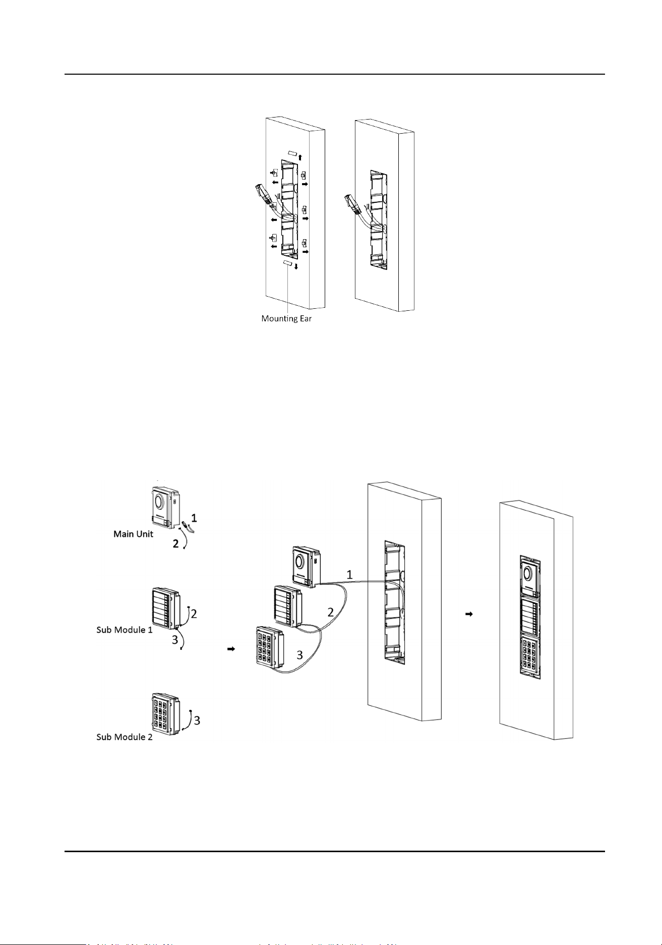
Figure 3-41 Remove the Mounng Ears
7.
Connect cables and insert the modules.
1) Connect Cable 1 and one end of Cable 2 to the corresponding interfaces of the main unit,
then insert the main unit into the upper grid.
2) Connect the other end of Cable 2 to the input interface of Sub Module 1. Connect one end of
Cable 3 to the output interface of Sub Module 1 and insert it into the middle grid.
3) Connect the other end of Cable 3 to the input interface of Sub Module 2. Insert it into the
boom grid.
Figure 3-42 Connect Cables and Insert Modules
Module Door Staon User Manual
53
Note
Cable 1 refers to the cables pulled out from the wall that connected to the main unit. Cable 2
and Cable 3 refer to the module-connecng line in the accessory package.
8.
Fix the cover and the main unit with 2 socket head cap screws by using a hexagon wrench
(supplied).
Figure 3-43 Fix the Cover
Module Door Staon User Manual
54
3.5 More-Than-Three Module Installaon
3.5.1 More-than-Three Module Surface Mounng
Before You Start
Figure 3-44 Mounng Frame
Note
●
It takes two three-module mounng frames. The dimension of three-module mounng frame
(W × H × D) is: 320.8 mm × 107 mm × 32.7 mm.
●
The dimensions above are for reference only. The actual size can be slightly dierent from the
theorecal dimension.
Steps
1.
Paste two Scker 1 onto the wall. Make sure the sckers are placed horizontally via measuring
with the gradienter.
2.
Drill 8 holes according to the screw holes on the
scker.
Note
●
The suggested size of hole is 6 (diameter) × 25 (depth) mm.
●
The suggested length of cables le outside is 270 mm.
3.
Pull out the cable through the cable hole of the le scker.
Module Door Staon User Manual
55
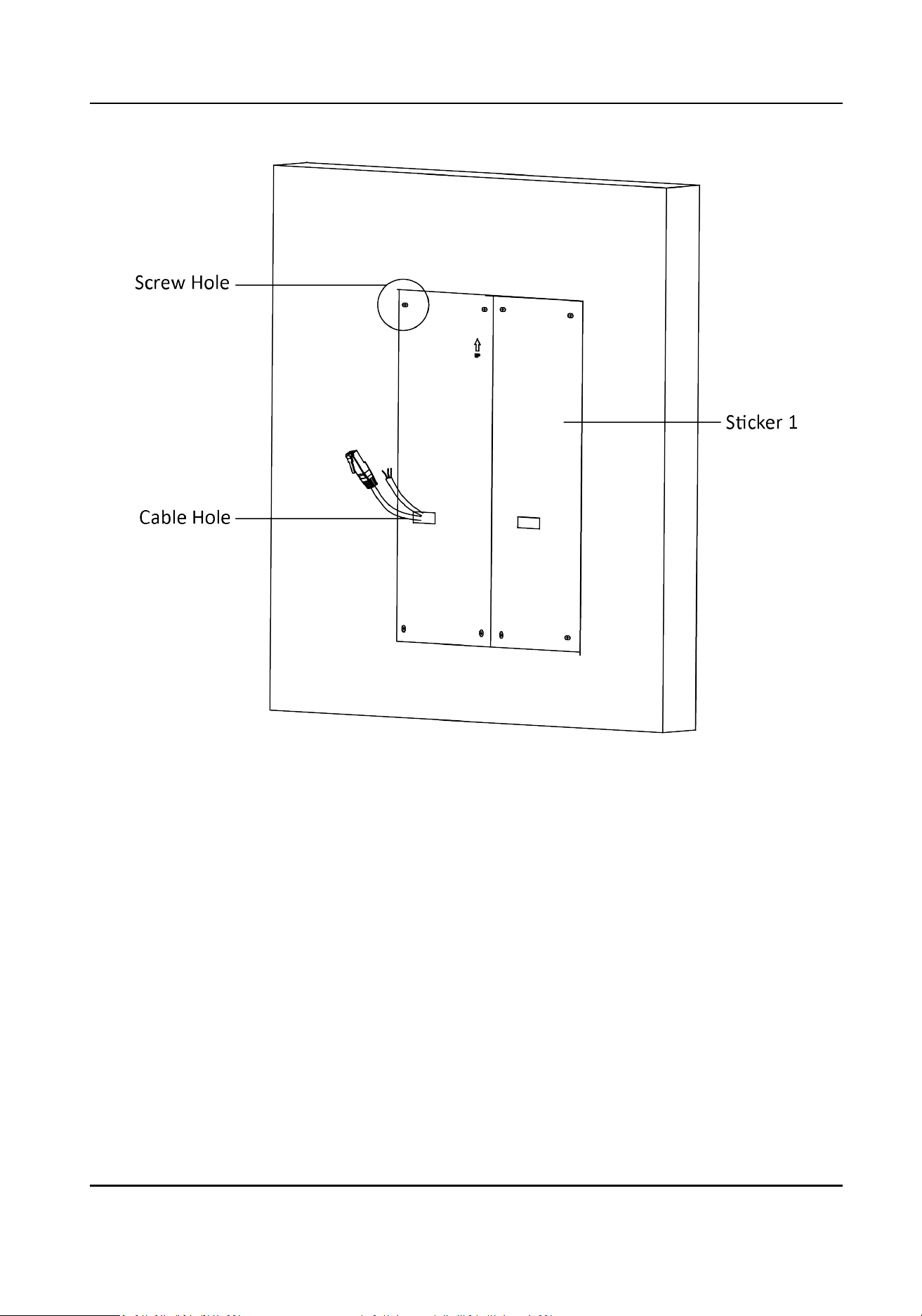
Figure 3-45 Drill Screw Holes
4.
Remove the sckers and insert the expansion sleeves into the screw holes.
5.
Thread the module-connecng line (400 mm) and grounding line across the thread hole of both
frames.
Module Door Staon User Manual
56
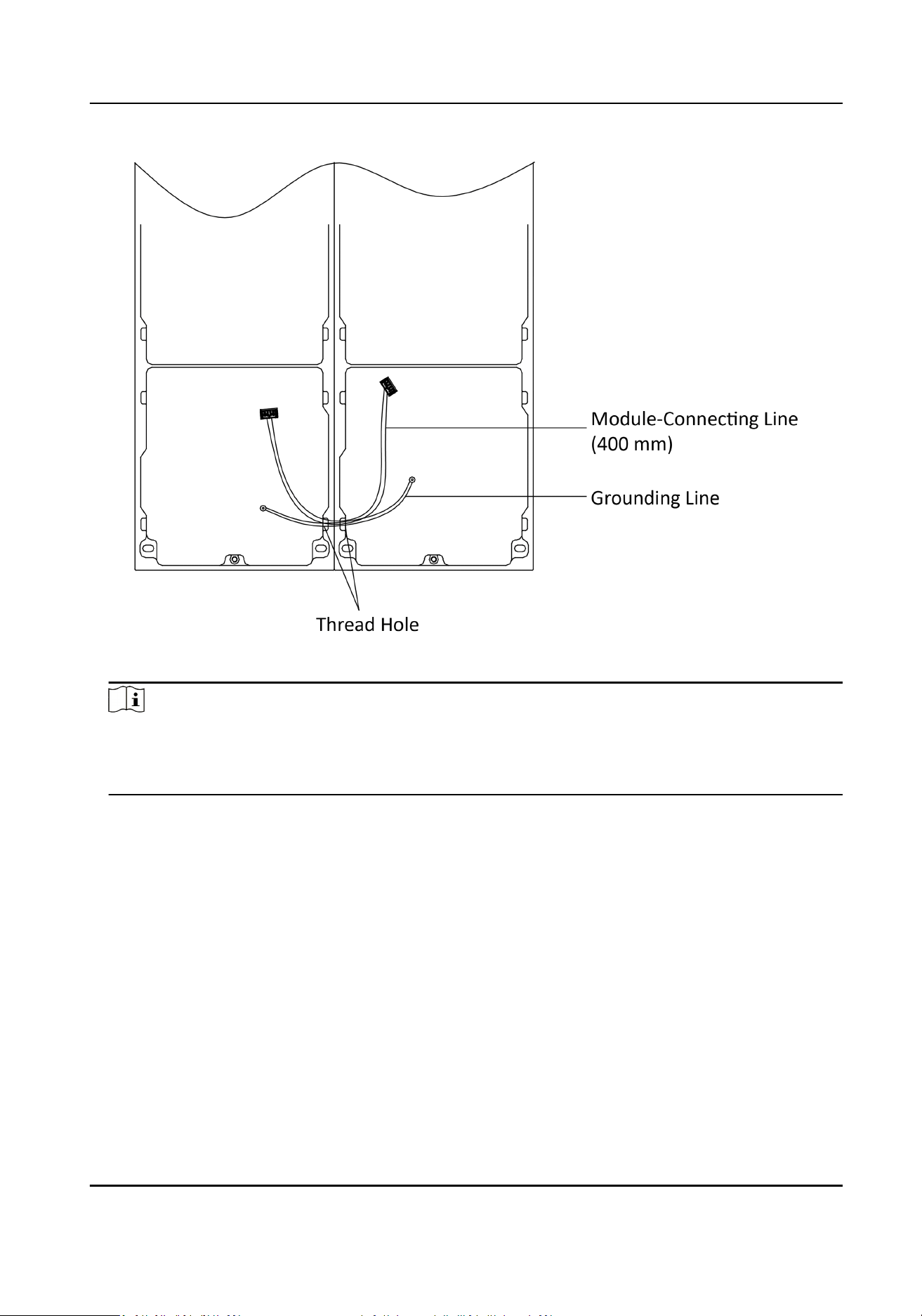
Figure 3-46 Place the Grounding Line and Module-Connecng Line
Note
●
There are 6 module-connecng lines in the package: 190 mm × 4 and 400 mm × 2.
●
Take the 400 mm module-connecng line for this step.
●
The green-yellow line in the package is for grounding.
6.
Fix the mounng frame onto the wall with 8 expansion bolts.
Module Door Staon User Manual
57
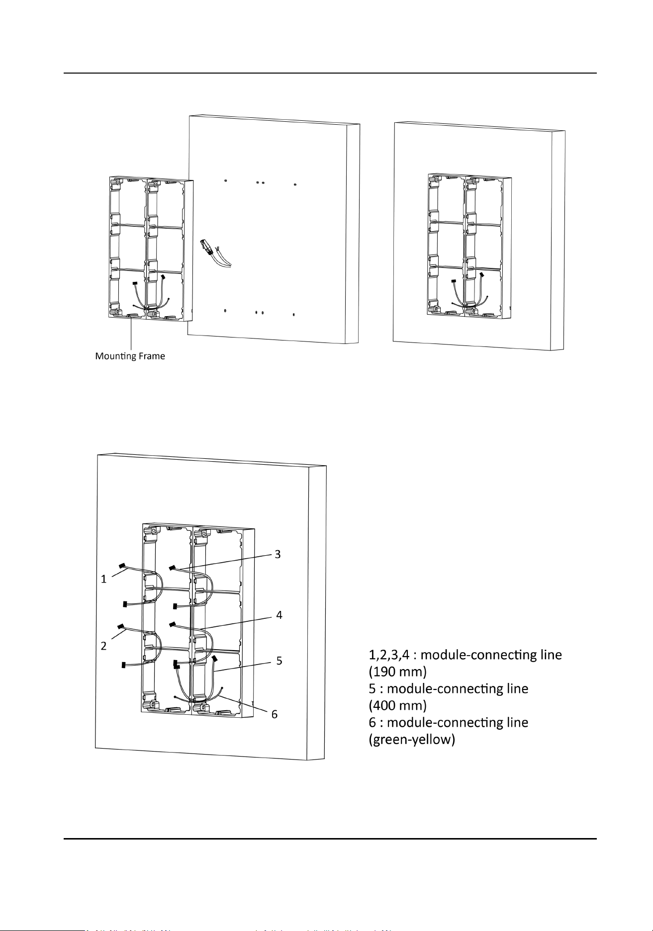
Figure 3-47 Fix the Mounng Frame
7.
Pass the main unit connecng line across the thread hole to the top grid of the le frame.
Thread the module-connecng line (190 mm) across the thread hole of the frame. The lines
should be placed as shown below.
Figure 3-48 Placement of Lines
Module Door Staon User Manual
58

8.
Connect the cables.
1) Connect the cables from the wall and module-connecng line 1 to the corresponding
interfaces of the main unit, then place the main unit into the upper grid.
2) Connect the other end of the
module-connecng line 1 to the input interface of the sub
module. Connect all sub modules via
module-connecng lines.
3) Organize the cable with cable
e in the package. The suggested cable connecon picture as
shown below.
Module Door Staon User Manual
59
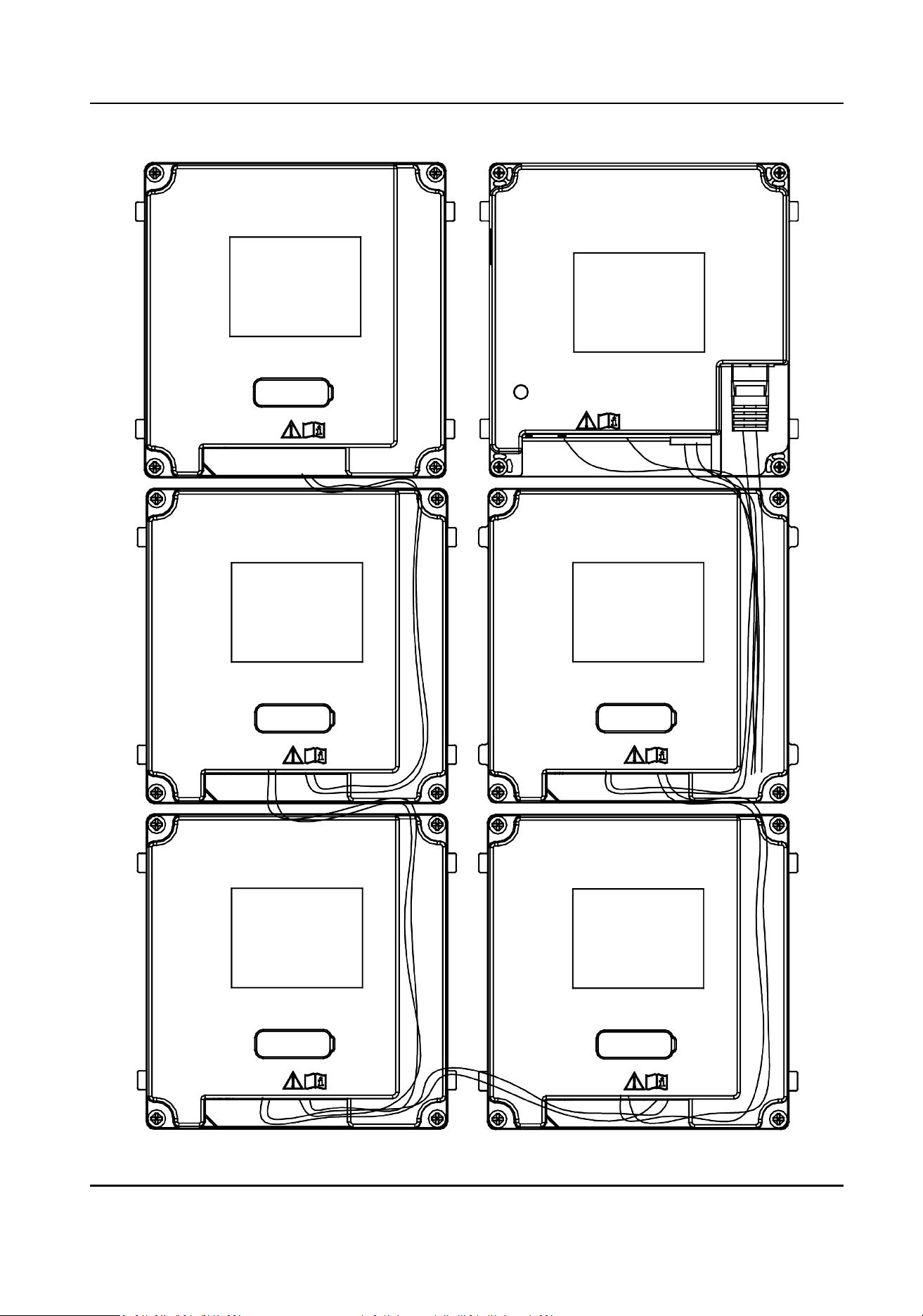
Figure 3-49 Line Connecon Eect Picture
Module Door Staon User Manual
60
9.
Insert the modules into the frame aer wiring. The main unit must be placed in the top grid on
the le.
Figure 3-50 Insert the Modules
10.
Pull the grounding line out and xed its two end to the screw on the cover.
Module Door Staon User Manual
61
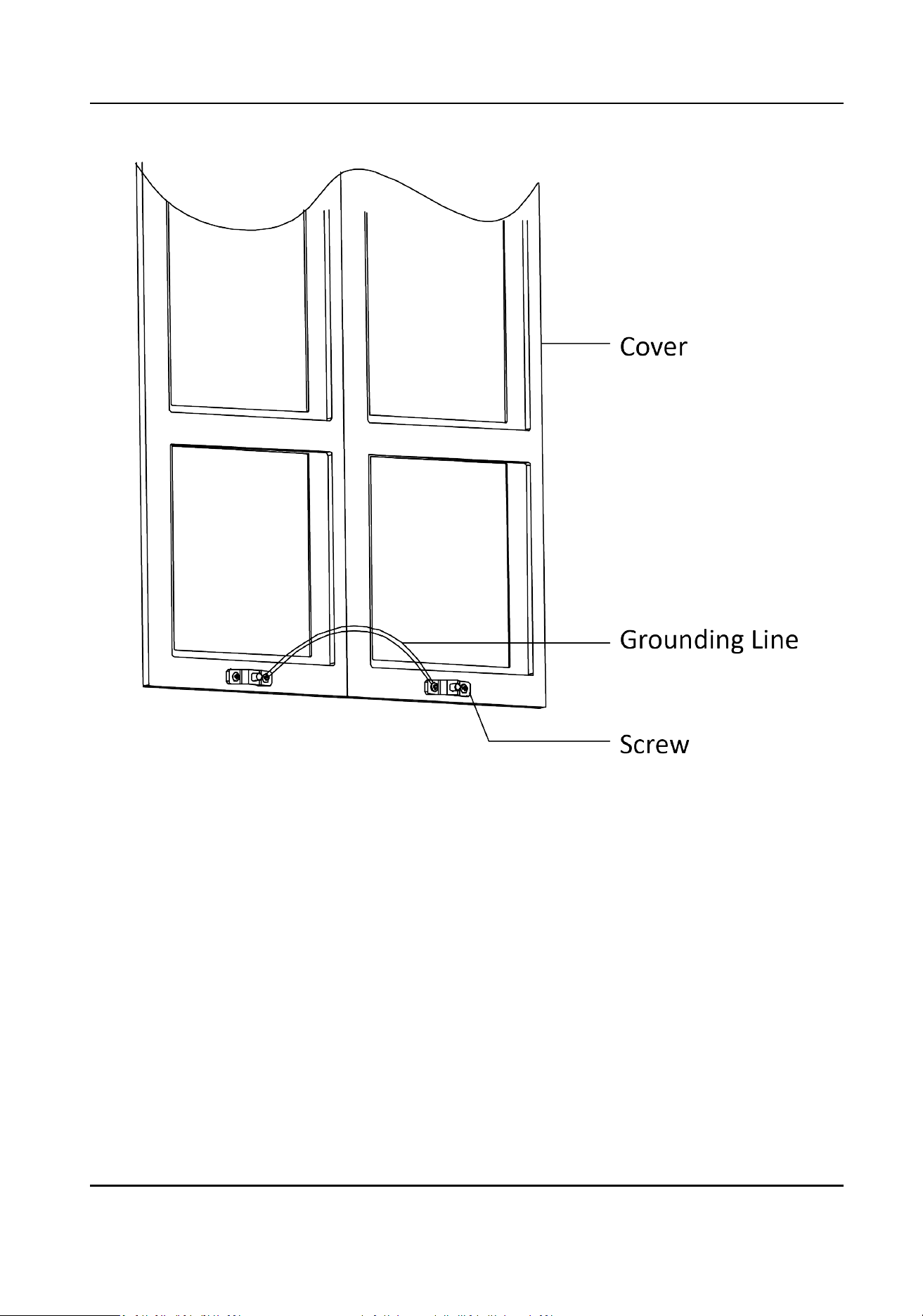
Figure 3-51 Connect the Grounding Line to the Cover
11.
Use the hexagon wrench in the package to x the cover onto the frame.
Module Door Staon User Manual
62
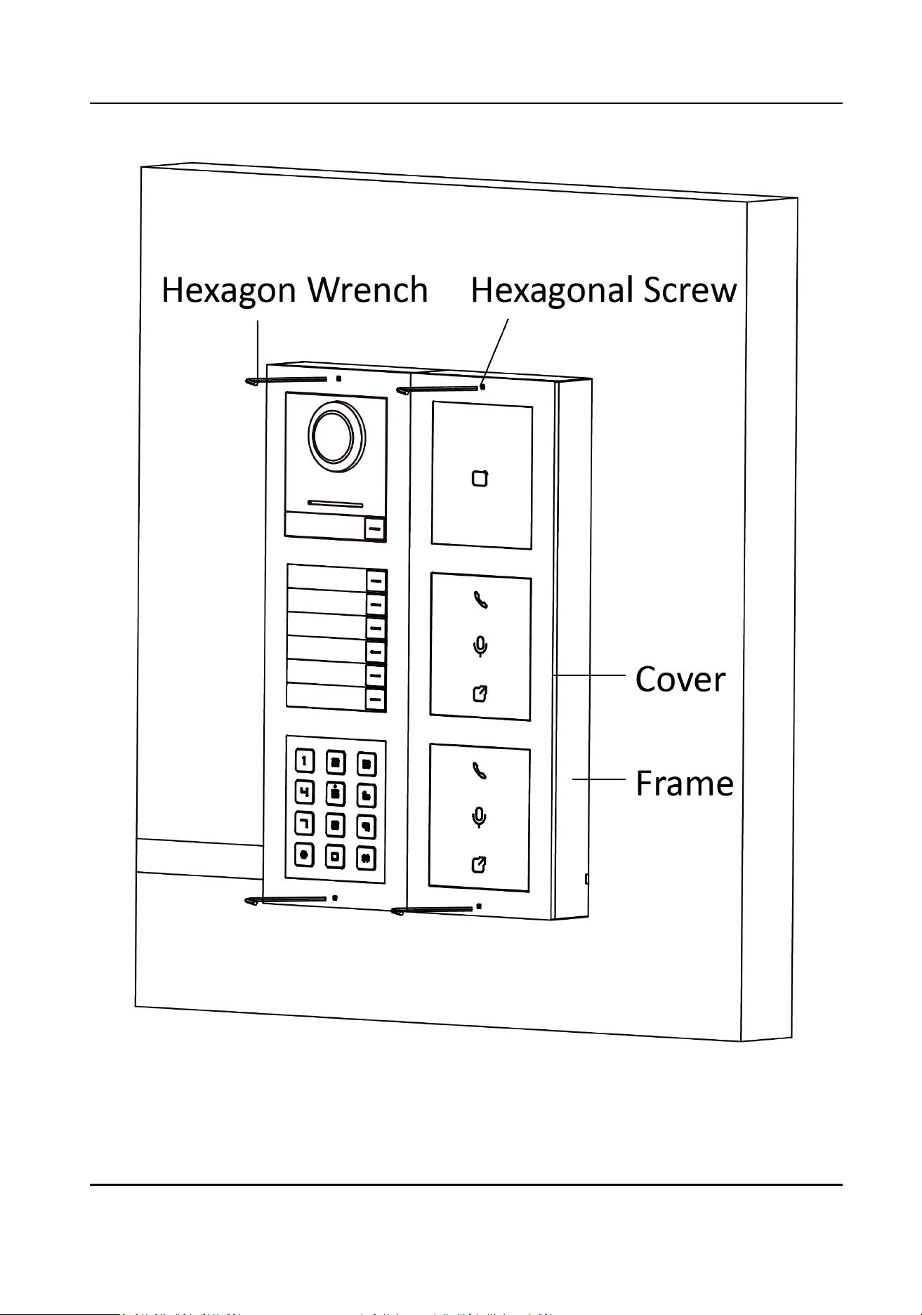
Figure 3-52 Fix the Cover
Module Door Staon User Manual
63
3.5.2 More-Than-Three Module Flush Mounng
Before You Start
Figure 3-53 Gang Box
Module Door Staon User Manual
64
Note
It takes two three-module gang boxes. The dimension of the gang box is: 338.8 (W) × 134 (H) × 56
(D) mm. The dimension is for reference only.
Steps
1.
Drill the installaon hole, and pull the cable out.The suggested dimension of installaon hole is
321.8 (W) × 315 (H) × 45.5 (D) mm. The suggested length of cables
le outside is 270 mm.
Figure 3-54 Cave the Installaon Hole
2.
Connect two gang boxes as below.
Module Door Staon User Manual
65
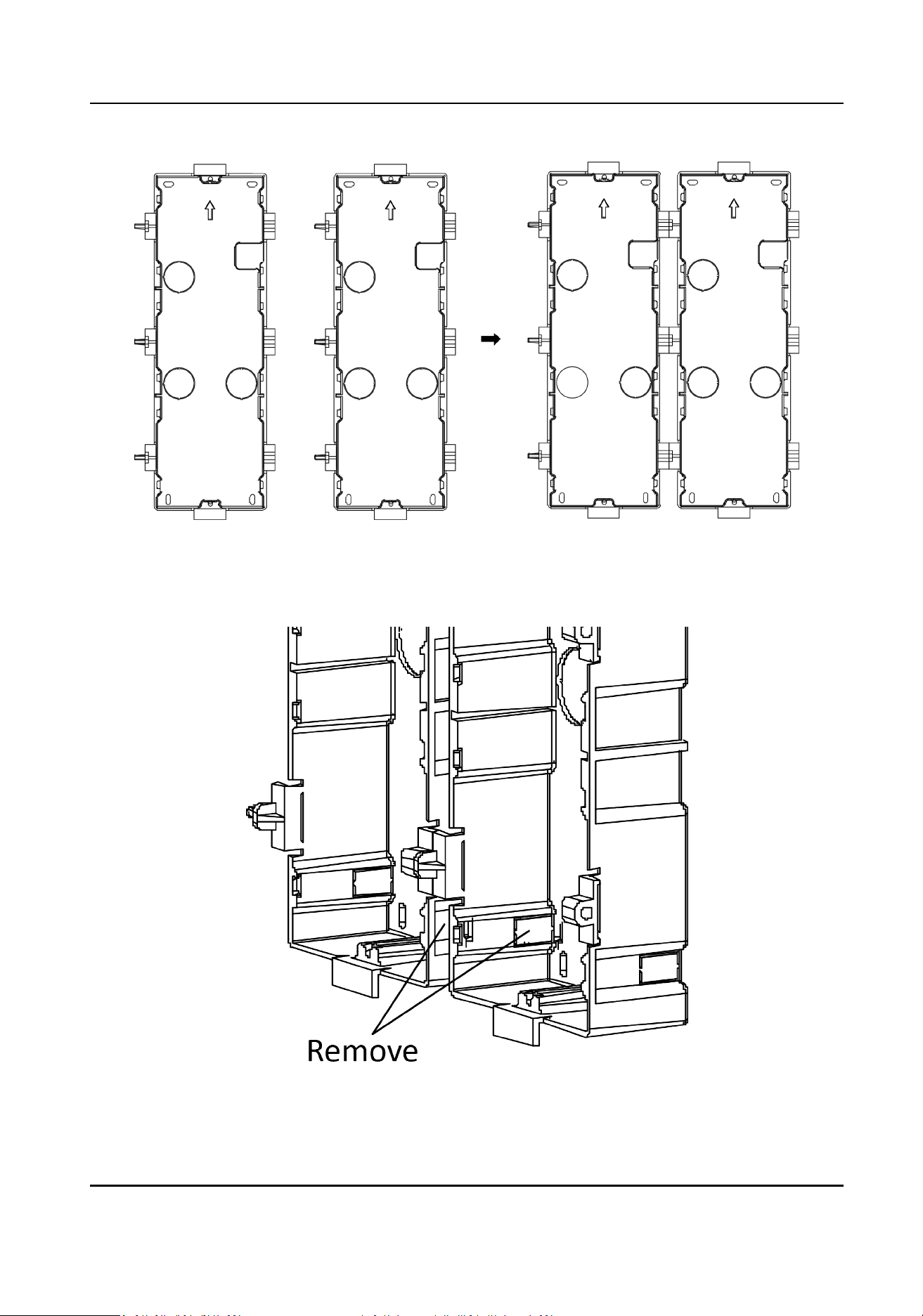
Figure 3-55 Connect Two Gang Boxes
3.
Select a cable entry and remove the plasc sheet.
4.
Remove the
plasc sheets on the side of the gang boxes (shown as 1 and 2) below:
Figure 3-56 Remove the Plasc Sheets
Module Door Staon User Manual
66
5.
Mark the gang box screw holes on the wall.
1) Route the cables through the gang box hole.
2) Insert the gang box into the installaon hole.
3) Mark the gang box screw holes'
posion with a marker, and take out the gang box.
Figure 3-57 Mark the Screw Holes
6.
Drill 8 holes according to the marks on the wall, and insert the expansion sleeves into the screw
holes. The suggested size of hole is 6 (diameter) × 45 (depth) mm.
7.
Fix the gang boxes with 8 expansion bolts.
Module Door Staon User Manual
67
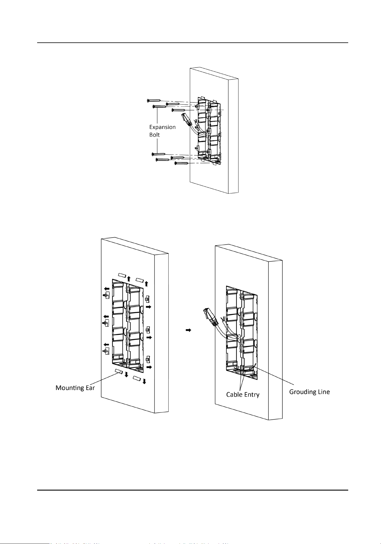
Figure 3-58 Fix the Gang Boxes
8.
Fill the gap between the gang box and wall with concrete. Remove the mounng ears with tool
aer concrete is dry. Route the grounding line through the cable entries.
Figure 3-59 Remove the Mounng Ears
Module Door Staon User Manual
68
Note
The green-yellow line in the package is for grounding.
9.
Connect cables and insert the modules.
1) Connect Cable 1 and one end of Cable 2 to the corresponding interfaces of the Main Unit,
then place the Main Unit into the upper grid of the le gang box.
2) Connect the other end of Cable 2 to the input interface of Sub Module 1. Connect one end of
Cable 3 to the output interface of Sub Module 1 and insert it into the middle grid of the le
gang box.
3) Finish the wiring and inserng according to the cable number and the posion shown as
below.
Figure 3-60 Install Mounng Frame
The cables connect to each module shown as below.
Module Door Staon User Manual
69
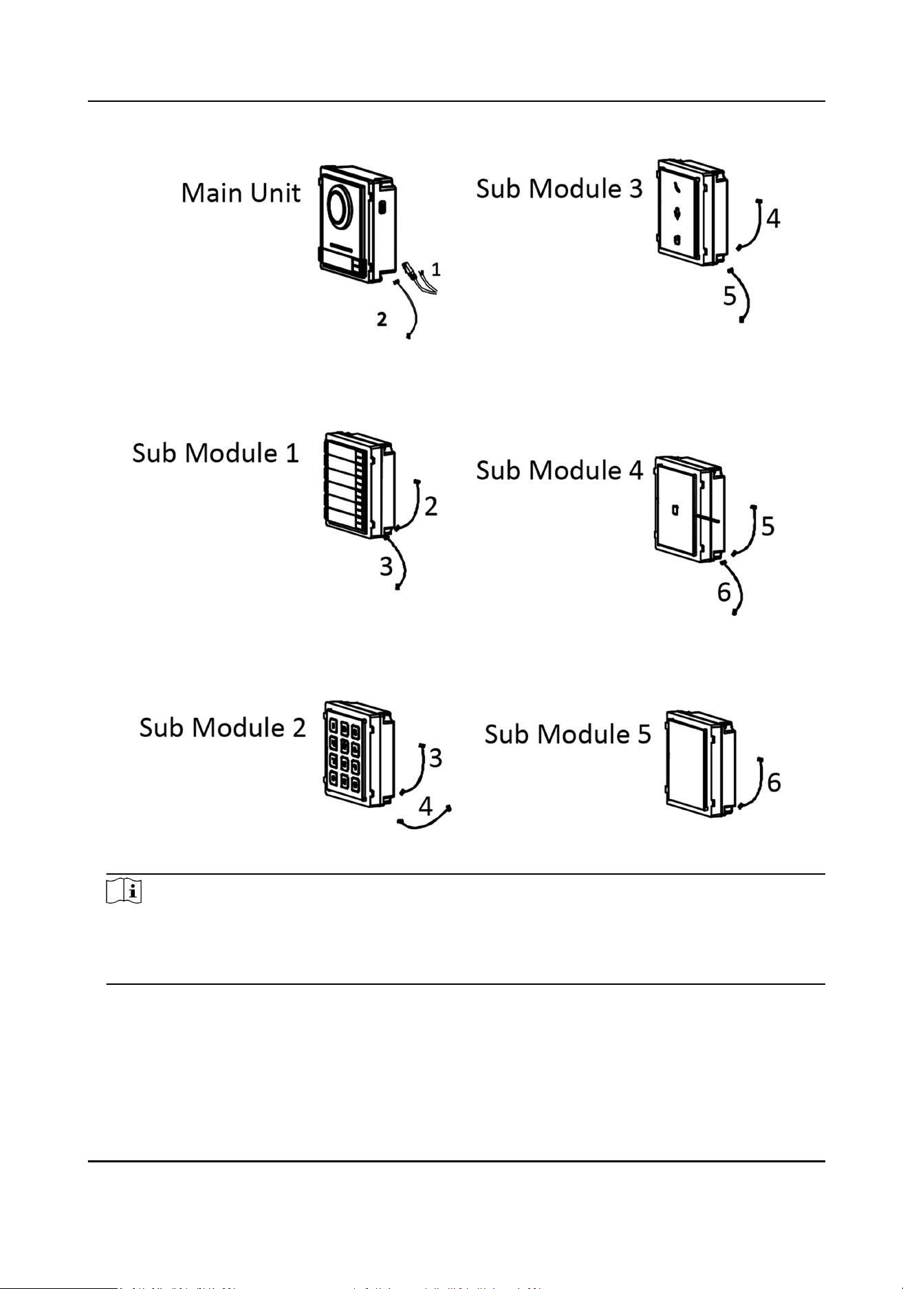
Figure 3-61 Cables Connecon
Note
●
Cable 2,3,5 and 6 are the module-connecng lines (190 mm) in the package.
●
Cable 4 is the module-connecng line (400 mm) in the package.
●
Main unit must be put in the top grid.
10.
Pull the grounding line out and xed its two end to the screw on the cover.
Module Door Staon User Manual
70

Figure 3-62 Connect the Grounding Line to the Cover
11.
Fix the cover with 2 socket head cap screws by using a hexagon wrench (supplied).
Module Door Staon User Manual
71
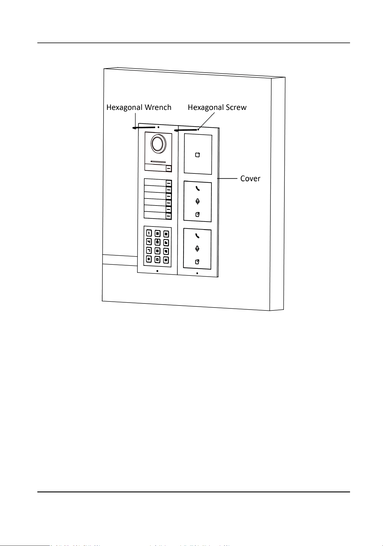
Figure 3-63 Fix the Cover
Module Door Staon User Manual
72
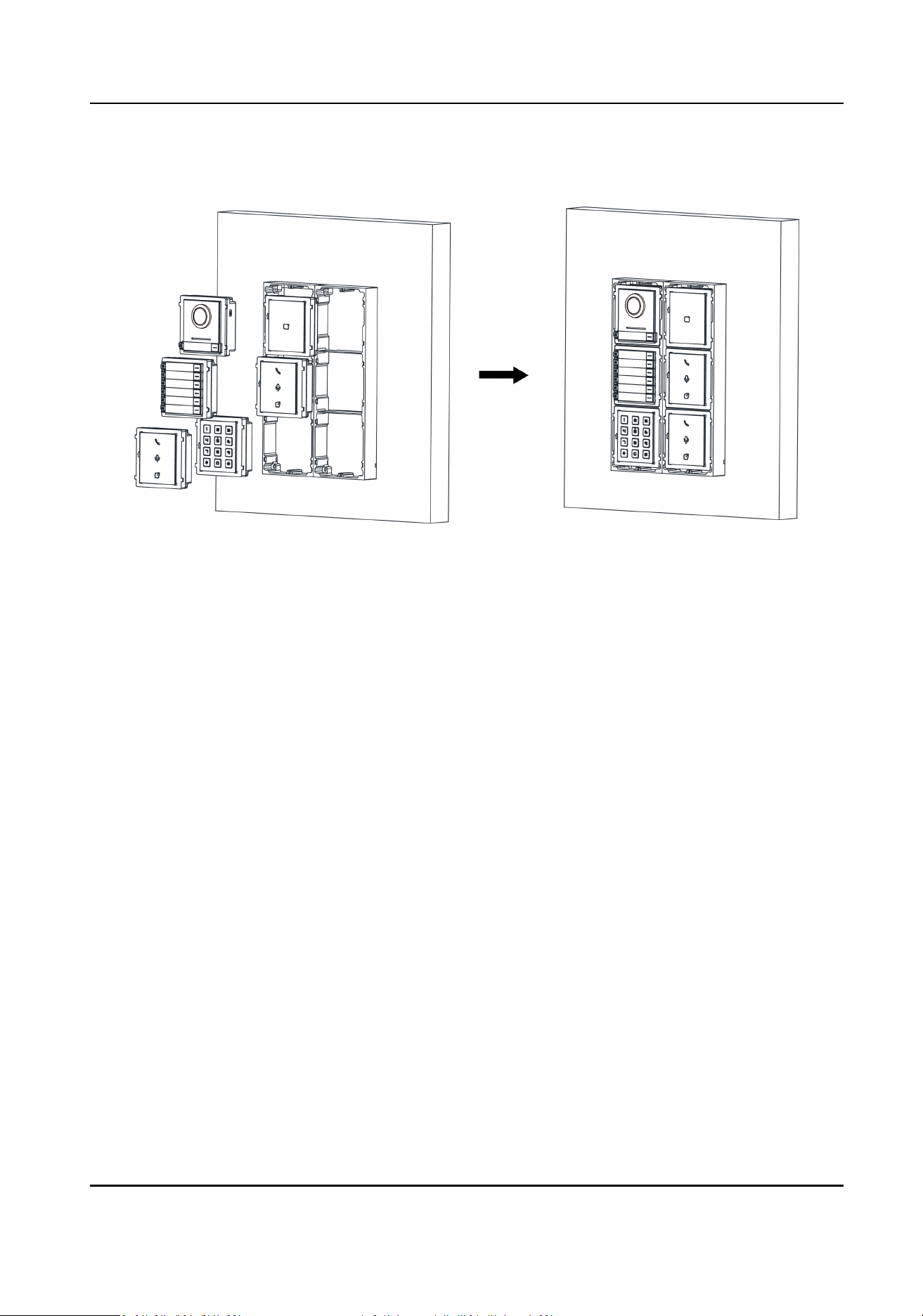
Chapter 4 Acvaon
4.1 Acvate Device via Client Soware
You can only congure and operate the door staon aer creang a password for the device
acvaon.
Default parameters of door staon are as follows:
●
Default IP Address: 192.0.0.65.
●
Default Port No.: 8000.
●
Default User Name: admin.
Steps
1.
Run the client
soware, click Maintenance and Management → Device Management → Device
to enter the page.
2.
Click Online Device.
3.
Select an
inacvated device and click Acvate.
4.
Create a password, and conrm the password.
Note
We highly recommend you to create a strong password of your own choosing (using a minimum
of 8 characters, including at least three kinds of following categories: upper case leers, lower
case leers, numbers, and special characters) in order to increase the security of your product.
And we recommend you change your password regularly, especially in the high security system,
changing the password monthly or weekly can beer protect your product.
5.
Click OK to acvate the device.
Note
●
When the device is not acvated, the basic operaon and remote operaon of device cannot
be performed.
●
You can hold the Ctrl or Shi key to select mulple devices in the online devices, and click the
Acvate buon to acvate devices in batch.
4.2 Edit Network Parameters
To operate and congure the device via LAN (Local Area Network), you need connect the device in
the same subnet with your PC. You can edit network parameters via iVMS-4200 client soware.
Steps
1.
Select an online
acvated device and click the Modify Nenfo.
2.
Edit the device IP address and gateway address to the same subnet with your computer.
3.
Enter the password and click OK to save the network parameters modicaon.
Module Door Staon User Manual
73

Note
●
The default port No. is 8000.
●
The default IP address of the door staon is 192.0.0.65.
●
Aer eding the network parameters of device, you should add the devices to the device list
again.
Module Door Staon User Manual
74

Chapter 5 Conguraon via Client Soware
5.1 Device Management
Device management includes device acvaon, adding device, eding device, and deleng device,
and so on.
Aer running the iVMS-4200, video intercom devices should be added to the client soware for
remote conguraon and management.
5.1.1 Add Online Device
Before You Start
Make sure the device to be added is in the same subnet with your computer. Otherwise, please
edit network parameters rst.
Steps
1.
Click Online Device to select an acve online device.
2.
Click Add.
3.
Enter corresponding
informaon, and click Add.
Module Door Staon User Manual
75
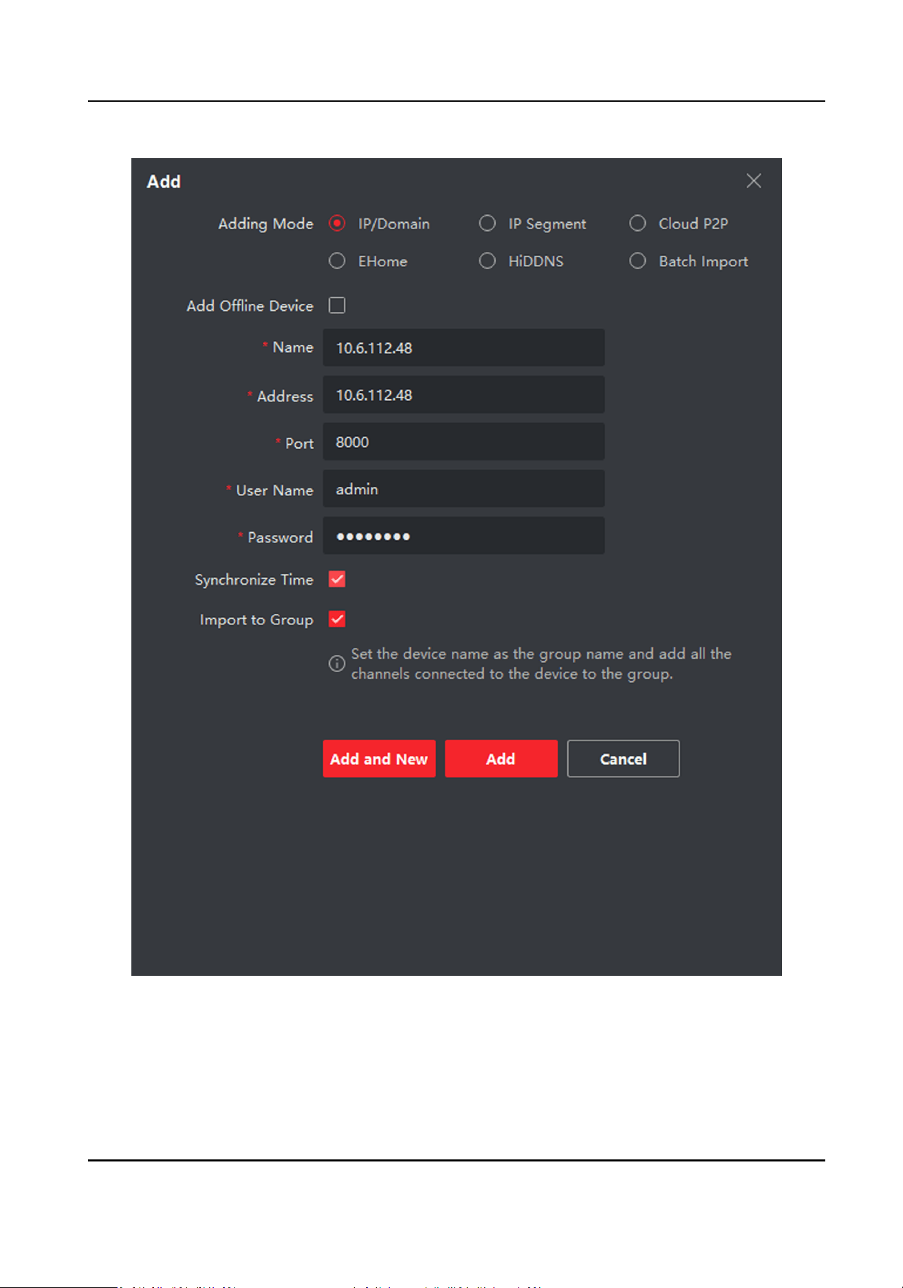
Figure 5-1 Add to the Client
Module Door Staon User Manual
76
5.1.2 Add Device by IP Address
Steps
1.
Click +Add to pop up the adding devices dialog box.
2.
Select IP/Domain as Adding Mode.
3.
Enter corresponding
informaon.
4.
Click Add.
5.1.3 Add Device by IP Segment
You can add many devices at once whose IP addresses are among the IP segment.
Steps
1.
Click +Add to pop up the dialog box.
2.
Select IP Segment as Adding Mode.
3.
Enter corresponding
informaon, and click Add.
5.2 Live View via Door
Staon
Steps
1.
On the main page of the client
soware, click Main View to enter the Live View page.
2.
In the le list of the window, double-click the device IP or click the play icon to live view.
3.
Oponal: On the Live View page, control-click and select Capture to get the picture of the live
view.
5.3 Remote
Conguraon
Click to set the parameters of the device.
Note
Run the browser, click → Internet Opons → Security to disable the Protected Mode.
5.3.1 Device Management
You can manage the linked device on the page.
Click Device Management to enter the sengs page.
Module Door Staon User Manual
77

Figure 5-2 Device Management
Add Device
●
Click Add to add the indoor staon or sub door staon. Enter the parameters and click OK to
add.
●
Click Import. Enter the
informaon of the device in the template to import devices in batch.
Export
Click Export to export the informaon to the PC.
Delete
Select the device and click Delete to remove the selected device from the list.
Refresh
Click Refresh to get the device informaon.
Oponal:
Set Device Informaon.
●
Click to edit device informaon.
●
Click to delete device informaon from the list.
●
Select Status and Device Type to search devices.
5.3.2 Local Parameters
Sengs
You can congure the parameters of the live view, record les and captured pictures. The record
les and captured pictures are the ones you record and capture by using the web browser. You can
also set and view the saving paths of the captured pictures and recorded videos on the PC that
running the web browser.
Module Door Staon User Manual
78
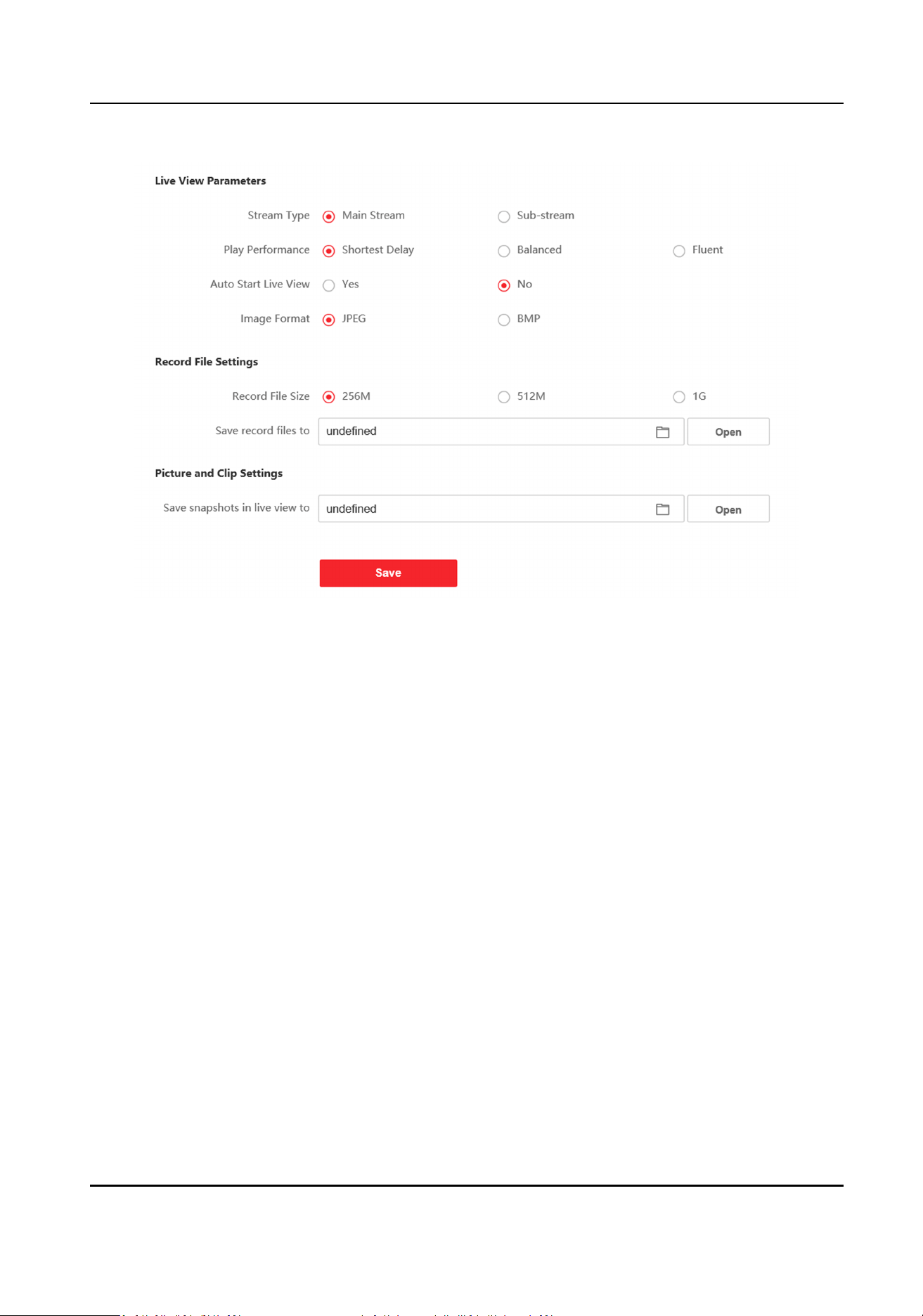
Figure 5-3 Local Parameters
Live View Parameters
Stream Type
Set the stream type as Main Stream or Sub-stream.
Play Performance
Set the live view performance to Shortest Delay, Balanced or Fluent.
Auto Start Live View
Check Yes to enable the funcon.
Image Format
Select the image format for picture capture.
Click Save to enable the sengs.
Record File Parameters
Record File Size
Select the packed size of the manually recorded and downloaded video les to 256M, 512M or
1G. Aer the selecon, the maximum record le size is the value you selected.
Save record les to
Set the saving path for the manually recorded video les.
Module Door Staon User Manual
79

Click Save to enable the sengs.
Picture and Clip Sengs
Save snapshots in live view to
Set the saving path of the manually captured pictures in live view mode.
Note
You can click Browse to change the directory for saving the clips and pictures, and click Open to
open the set folder of clips and picture saving.
Click Save to enable the sengs.
5.3.3 System
Sengs
Follow the instrucons below to congure the system sengs, include System Sengs,
Maintenance, Security, and User Management, etc.
Click System to enter the sengs page.
Basic
Informaon
Click System Sengs → Basic Informaon to enter the sengs page. On the page, you can edit
Device Name and Device No. Set the Language and System Type according to your needs.
Click Save to enable the
sengs.
Time
Sengs
Click System Sengs → Time Sengs to enter the sengs page. Select the Time Zone of your
locaon from the drop-down list.
●
Enable NTP, set the Server Address, NTP Port and Interval.
●
Enable Manual Time Sync., set the
me manually or check the Sync. with computer me.
Click Save to enable the
sengs.
DST
Click System Sengs → DST to check Enable DST. Set the parameters according to your needs and
click Save to enable the sengs.
About
Click System Sengs → About and click Open Source Soware Licenses to view the details.
Maintenance
Click
Maintenance → Upgrade & Maintenance to enter the sengs page.
Module Door Staon User Manual
80
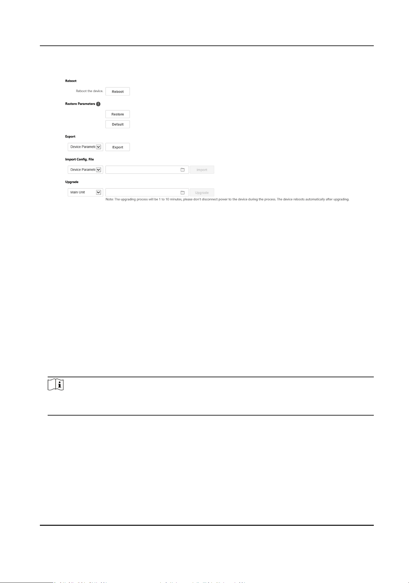
Figure 5-4 Maintenance
●
Reboot: Click Reboot to reboot the device.
●
Restore
Click Restore to reset all the parameters, except the IP parameters and user informaon, to
the default
sengs.
Default
Click Default to restore all parameters to default sengs.
●
Export parameters:
1. Select Device Parameters, and click Export to pop up the dialog box.
2. Set and
conrm the encrypon password.
3. Click OK to export parameters.
●
Import
Cong. File:
1. Click browse icon to select the conguraon le.
2. Click Import and enter the encrypon password to import.
●
Upgrade: Click browse icon to select the upgrade le.
Note
The upgrading process will last 1 to 10 minutes, do not power o during the upgrading. The
device reboots automacally aer upgrading.
Security Service
Click Security → Security Service to enter the sengs page. On the page, you can enable SSH
according to your actual needs.
Click Save to enable the
sengs.
User Management
Click User Management to enter the sengs page.
Module Door Staon User Manual
81
Administrator can edit the permission for the users.
Note
We highly recommend you to create a strong password of your own choosing (using a minimum of
8 characters, including at least three kinds of following categories: upper case leers, lower case
leers, numbers, and special characters) in order to increase the security of your product. And we
recommend you change your password regularly, especially in the high security system, changing
the password monthly or weekly can beer protect your product.
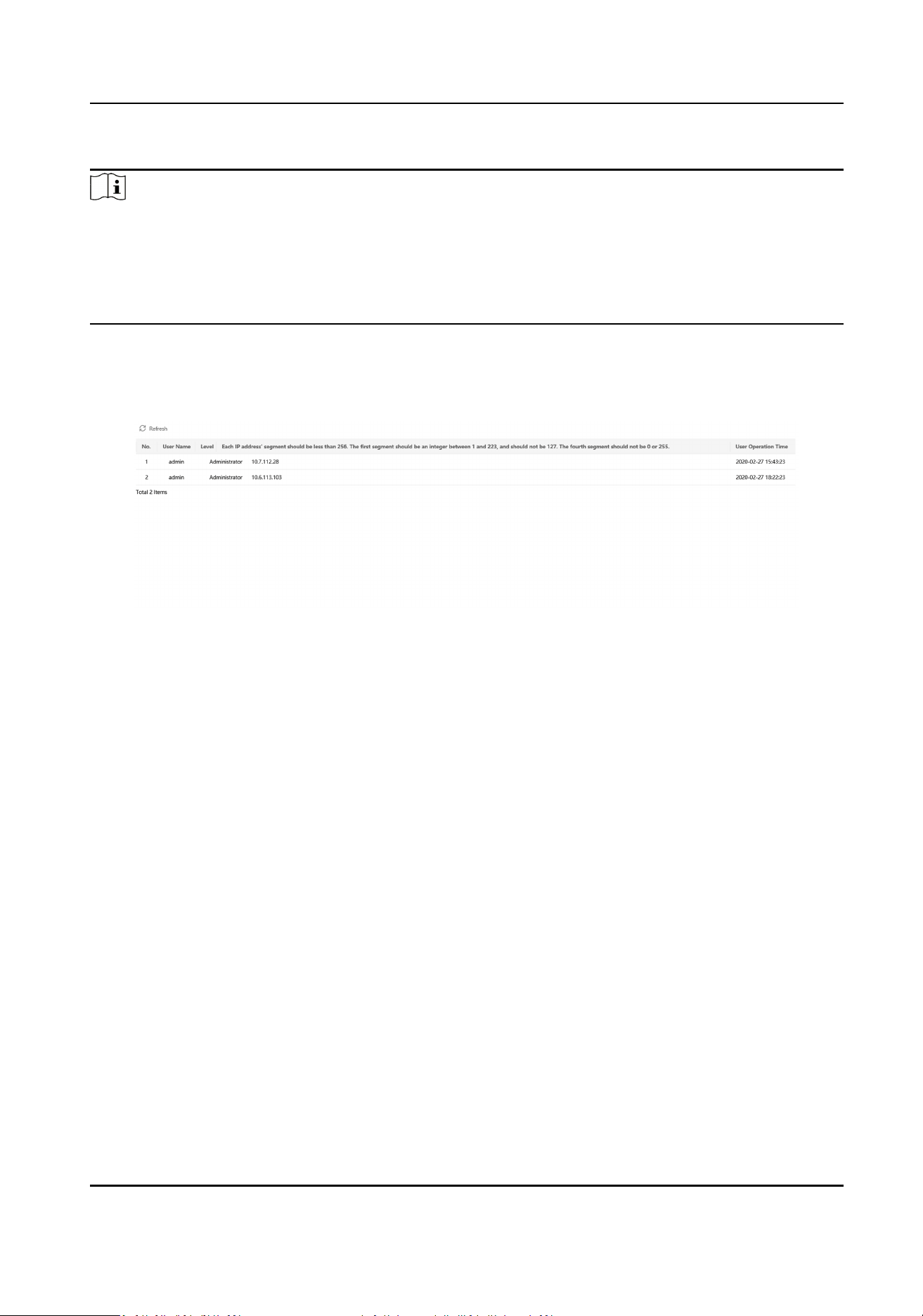
Online Users
Click
User Management → Online Users to enter the page.
Figure 5-5 Online Users
Click Refresh to get the present informaon.
Arming/Disarming
Informaon
Click User Management → Arming/Disarming Informaon to view the informaon. Click Refresh
to get the present
informaon.
5.3.4 Network
Sengs
TCP/IP Sengs
TCP/IP sengs must be properly congured before you operate the device over network. The
device supports IPv4.
Steps
1.
Click Network → Basic
Sengs → TCP/IP to enter the sengs page.
Module Door Staon User Manual
82
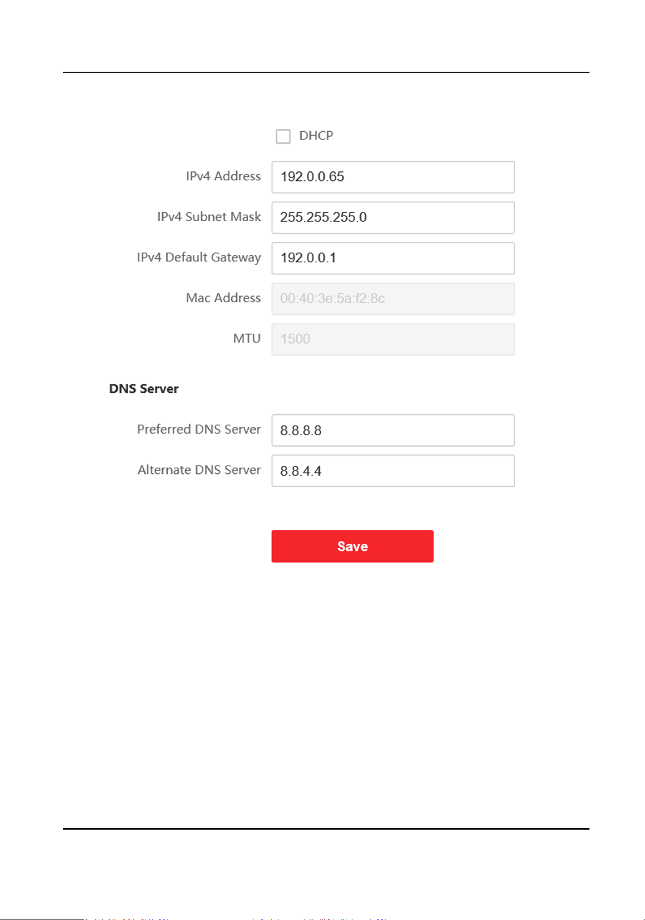
Figure 5-6 TCP/IP Sengs
2.
Congure the network parameters.
-
Check DHCP, the device will get the parameters automacally.
-
Set the IPv4 Address, IPv4 Subnet Mask and IPv4 Default Gateway manually.
3.
Congure the corresponding DNS server parameters.
4.
Click Save to enable the
sengs.
Port
Sengs
Steps
1.
Click Network → Basic Sengs → Port to enter the sengs page.
Module Door Staon User Manual
83
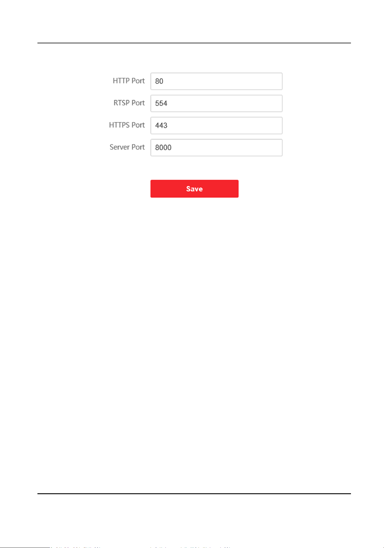
Figure 5-7 Port Sengs
2.
Set the ports of the device.
HTTP Port
The default port number is 80, and it can be changed to any port No. which is not occupied.
HTTPS Port
The default port number is 443, and it can be changed to any port No. which is not occupied.
RTSP Port
The default port number is 554.
Server Port
The default server port number is 8000, and it can be changed to any port No. ranges from
2000 to 65535.
3.
Click Save to enable the
sengs.
SIP
Seng
Steps
1.
Click Network → Basic
Sengs → SIP to enter the sengs page.
Module Door Staon User Manual
84
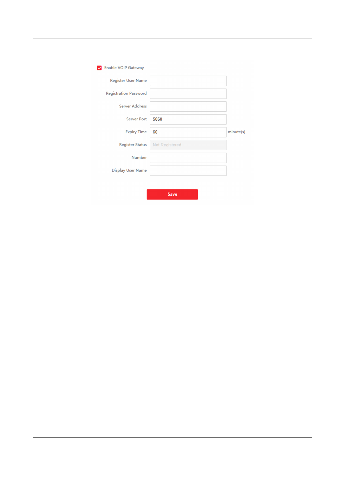
Figure 5-8 SIP Sengs
2.
Check Enable VOIP Gateway.
3.
Congure the SIP parameters.
4.
Click Save to enable the sengs.
FTP
Sengs
Steps
1.
Click Network → Advanced → FTP to enter the
sengs page.
Module Door Staon User Manual
85
Figure 5-9 FTP Sengs
Module Door Staon User Manual
86
2.
Check Enable FTP.
3.
Select Server Type.
4.
Input the Server IP Address and Port.
5.
Congure the FTP Sengs, and the user name and password are required for the server login.
6.
Set the Directory Structure, Parent Directory and Child Directory.
7.
Set the picture naming rules.
8.
Click Save to enable the sengs.
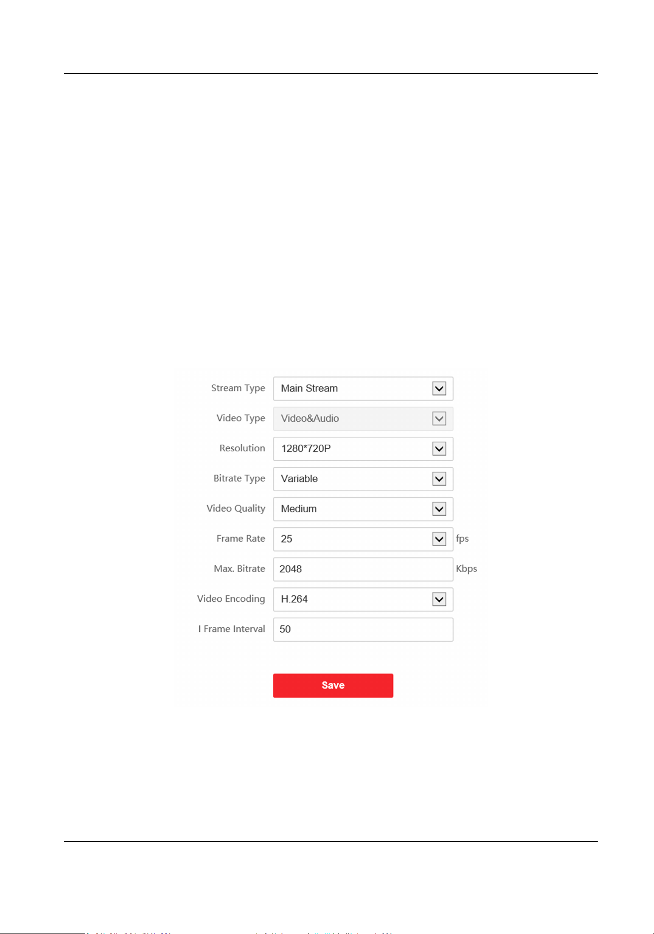
5.3.5 Video & Audio Sengs
Video Parameters
Steps
1.
Click Video/Audio → Video to enter the
sengs page.
Figure 5-10 Video Parameters
2.
Select the Stream Type.
3.
Congure the video parameters.
Stream Type
Module Door Staon User Manual
87

Select the stream type to main stream or sub stream.
Video Type
Select the stream type to video stream, or video & audio composite stream. The audio signal
will be recorded only when the Video Type is Video & Audio.
Resoluon
Select the resoluon of the video output.
Bitrate Type
Select the bitrate type to constant or variable.
Video Quality
When bitrate type is selected as Variable, 6 levels of video quality are selectable.
Frame Rate
Set the frame rate. The frame rate is to describe the frequency at which the video stream is
updated and it is measured by frames per second (fps). A higher frame rate is advantageous
when there is movement in the video stream, as it maintains image quality throughout.
Max. Bitrate
Set the max. bitrate from 32 to 16384 Kbps. The higher value corresponds to the higher video
quality, but the
beer bandwidth is required.
Video Encoding
The device supports H.264.
I Frame Interval
Set I Frame Interval from 1 to 400.
4.
Click Save to save the sengs.
Audio Parameters
Steps
1.
Click Video/Audio → Audio to enter the
sengs page.
Module Door Staon User Manual
88
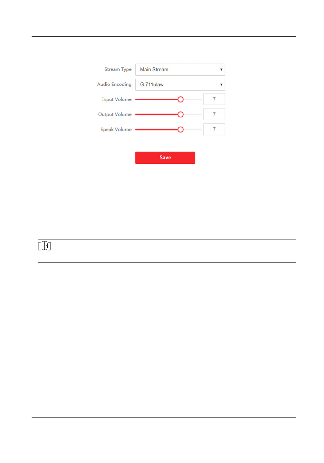
Figure 5-11 Audio Sengs
2.
Congure the stream type and the audio encoding type.
Stream Type
Select the stream type to main stream or sub stream.
Audio Encoding
The device support G.711ulaw and G.711 alaw.
3.
Adjust the Input Volume, Output Volume and Speak Volume.
Note
Available range of volume: 0 to 10.
4.
Click Save to save the sengs.
5.3.6 Image
Sengs
Display Sengs
Congure the image adjustment, backlight sengs and other parameters in display sengs.
Steps
1.
Click Image → Display
Sengs to enter the display sengs page.
Module Door Staon User Manual
89
Figure 5-12 Display Sengs
2.
Select the Format.
3.
Set the display parameters.
WDR
Wide Dynamic Range can be used when there is a high contrast of the bright area and the
dark area of the scene.
Brightness
Brightness describes bright of the image, which ranges from 1 to 100.
Contrast
Contrast describes the contrast of the image, which ranges from 1 to 100.
Saturaon
Saturaon describes the colorfulness of the image color, which ranges from 1 to 100.
Sharpness
Sharpness describes the edge contrast of the image, which ranges from 1 to 100.
4.
Set the Day/Night Mode.
Module Door Staon User Manual
90
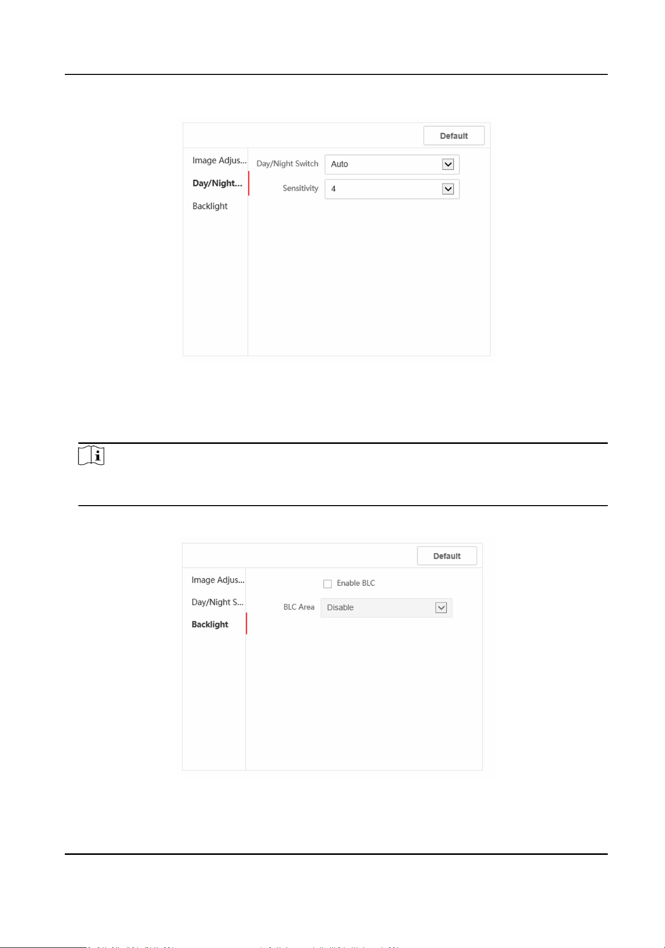
Figure 5-13 Day/Night Mode
-
Set Day Mode or Night Mode manually.
-
Set the mode as Auto and edit the
sensivity according to your needs.
-
Set the mode as Scheduled-Switch. Set the start
me and end me.
Note
Dayme is from congured start me to congured me. The rest of the me is set as night by
default.
5.
Set the backlight parameters.
Figure 5-14 Backlight
Module Door Staon User Manual
91
1) Check the checkbox to enable BLC.
2) Select BLC Area.
6.
Click Save to enable the sengs.
OSD Sengs
You can customize the camera name, me/date format, display mode, and OSD size displayed on
the live view.
Steps
1.
Click Image → OSD Sengs to enter the sengs page.
2.
Check the corresponding checkbox to select the display of camera name, date or week if
required.
3.
Edit the Camera Name.
4.
Select from the drop-down list to set the Time Format and Date Format.
5.
Adjust the OSD
posion.
6.
Click Save to enable the sengs.
Target Cropping
Steps
1.
Click Image → Crop to enter the page.
2.
Check Enable Target Cropping to enable the
funcon.
3.
Click to capture photo.
4.
Click
to start recording.
5.
Select Cropping Resoluon.
6.
Click Save.
Note
●
You can select Cropping Resoluon as 704*576, 1280*720, or 1920*1080.
●
You can zoom in or zoom out the image by selecng Cropping Resoluon aer clicking Save.
5.3.7 Event Sengs
Moon Detecon
Moon detecon detects the moving objects in the congured security area, and a series of
acons can be taken when the alarm is triggered.
Steps
1.
Click Event → Moon to enter the sengs page.
Module Door Staon User Manual
92
Figure 5-15 Moon Detecon
2.
Slide Enable Moon Detecon to enable the funcon.
3.
Click Draw Area. Click and drag the mouse on the live video to draw a moon detecon area.
Click Save to save the sengs.
Clear Area
Click X to clear all of the areas.
Adjust Sensivity Move the slider to set the sensivity of the detecon.
4.
Click Arming Schedule to edit the arming schedule.
Module Door Staon User Manual
93

5.
Click on the me bar and drag the mouse to select the me period. Click Save to save the
sengs.
Delete Schedule Click Delete to delete the current arming schedule.
6.
Click Linkage Method to enable the linkages.
Nofy Security Center
Send an excepon or alarm signal to the remote management soware when an event
occurs.
7.
Click Save to enable the
sengs.
Event Linkage
Steps
1.
Click Event → Basic Event → Event Linkage to enter the
sengs page.
Module Door Staon User Manual
94
Figure 5-16 Event Linkage
Module Door Staon User Manual
95
2.
Select the Major Type as Device Event or Door Event.
3.
Select the type of the Normal Linkage for the event.
4.
Click Save to enable the sengs.
5.3.8 Schedule Sengs
You can create call schedule, or else the device will call indoor staon all day by default.
Steps
1.
Click Schedule → Video Intercom → Call Schedule .
2.
Click the next row below Enable Indoor Staon All Day by Default.
3.
Enter Schedule Name.
4.
Select Call Type.
5.
Set Weekly Schedule.
1) Click Weekly Schedule.
Figure 5-17 Weekly Schedule
2) Drag mouse to set the schedule according to the actual needs.
3)
Oponal: Click the copy icon to copy the schedule to other days according to the actual
needs.
4) Click Save.
6.
Set Holiday Schedule.
1) Click Holiday Schedule.
Module Door Staon User Manual
96
Figure 5-18 Holiday Schedule
2) Click Add.
3) Set Start Time and End Time.
4) Select Call Type.
5) Drag mouse to set the schedule according to the actual needs.
6) Click OK.
7) You can edit or delete the schedule according to the actual needs.
8) Click Save.
Note
The holiday schedule have higher priority than weekly schedule when you set the two
schedule at the same me.
5.3.9 Intercom Sengs
Device No. Sengs
Steps
1.
Click Device No. to enter the page.
Module Door Staon User Manual
97
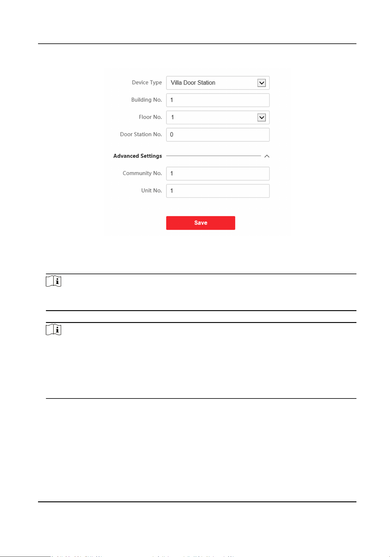
Figure 5-19 Villa Door Staon No. Sengs
2.
Select the device type from the drop-down list, and set the corresponding informaon including
Building No., Floor No., Door Staon No., Community No. and Unit No.
Note
When you select Doorphone as Device Type, only Community No., Building No. and Unit No.
can be set.
3.
Click Save to enable the device number conguraon.
Note
●
For main door staon (D series or V series), the No. is 0.
●
For sub door staon (D series or V series), the No. cannot be 0. The No.of sub door staon
ranges from 1 to 99.
●
For each villa or building, at least one main door
staon (D series or V series) should be
congured, and one sub door staons (D series or V series) can be customized.
●
For one main door staon (D series or V series), up to 8 sub door staons can be congured.
Linked Network Sengs
Steps
1.
Go to Intercom → Session
Sengs to enter the sengs page.
2.
Set Register Number and Registraon Password.
3.
Set Main
Staon IP and VideoIntercom Server IP.
Module Door Staon User Manual
98
4.
Enable Protocol 1.0.
5.
Click Save to enable the sengs.
Time Parameters
Go to Intercom → Time Parameters to enter the page.
Congure Max. Call Duraon, Max. Message Duraon, Max. Ring Duraon, and click Save.
Note
●
Max. call duraon between the module indoor staon and client ranges from 90 s to 120 s. The
call will end automacally when the actual calling duraon is longer than the congured one.
●
Max. message duraon ranges from 30 s to 60 s. The message will end automacally when the
actual message
duraon is longer than the congured one.
●
Max. ring
duraon refers to the maximum duraon of the module indoor staon when it is
called without being accepted. Max. ring
duraon ranges from 65 s to 255 s.
Ring-Back Tone Sengs
Click Intercom → Ringbacktone Sengs to enter the sengs page.
Click Add to select the ring tone from PC.
Note
Available Audio Format: WAV、AAC, Size: Less than 600 KB, Sample Rate: 8000Hz, Mono.
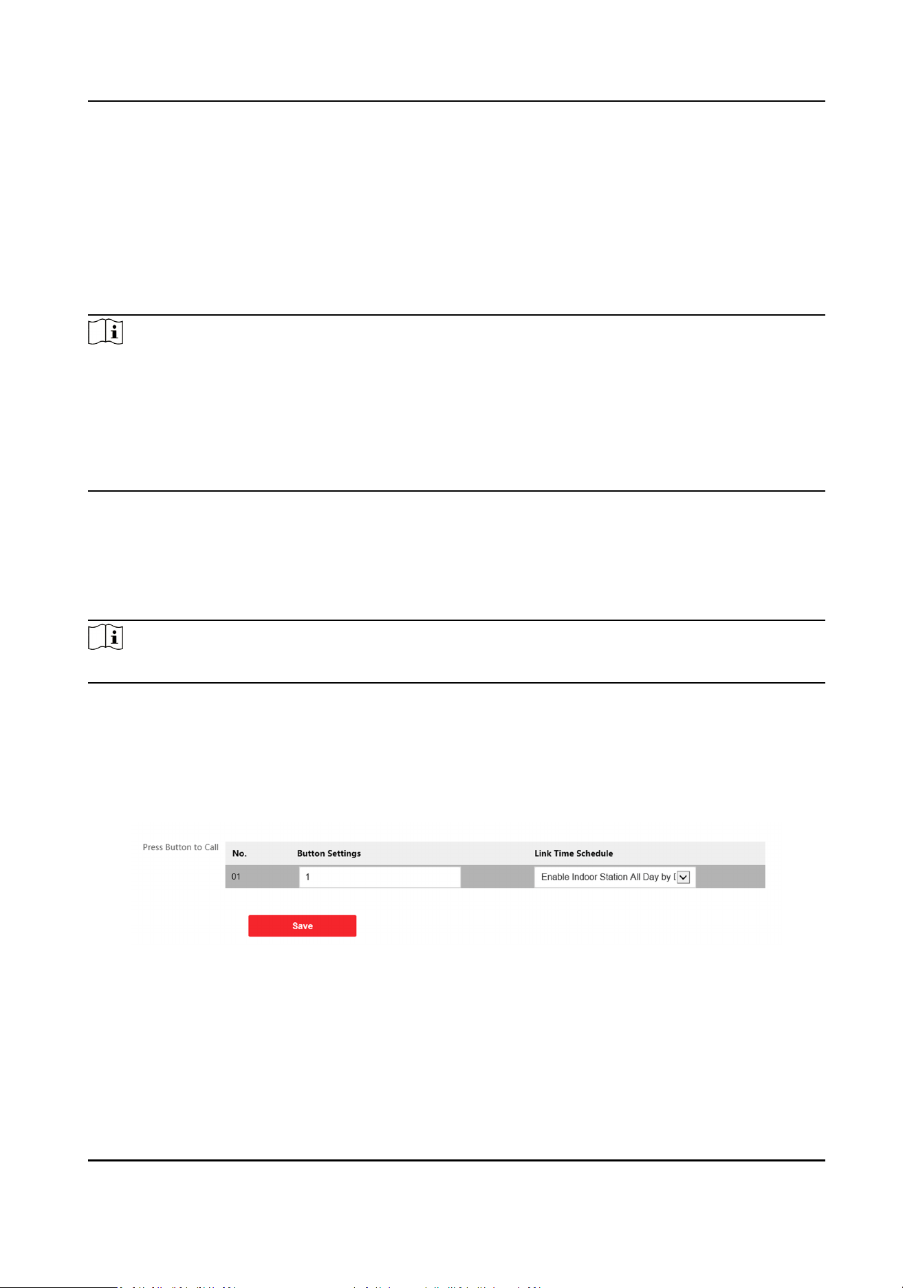
Press Buon to Call
Steps
1.
Go to Intercom → Press Buon to Call to enter the sengs page.
Figure 5-20 Press Buon to Call
2.
Edit room No. in the buon sengs and select Link Time Schedule.
Module Door Staon User Manual
99
Note
●
The number of buons may vary with dierent models. Please refer to the actual product.
●
The schedule sengs refers to Schedule Sengs for details.
3.
Click Save to enable the sengs.
Input and Output
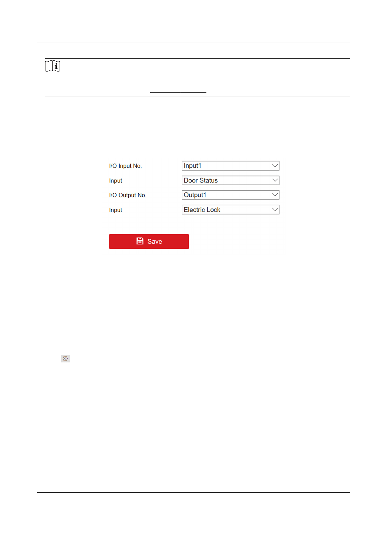
Go to Intercom → I/O Sengs to enter the sengs page.
Figure 5-21 IO Input and Output
Select I/O Input No., Input, I/O Output No. and Output.
Click Save to enable the
sengs.
Sub Module
Conguraon
Steps
1.
Click Intercom → Sub Module
Conguraon , and you can view the sub module informaon,
including No., module type, status, and version.
2.
Click
to edit the sub module.
Display Module
●
Slide to adjust Screen Backlight Brightness.
●
Slide Enable Buzzer to enable the
funcon.
Touch-Display Module
●
Slide to adjust Screen Backlight Brightness.
●
Slide Enable Buzzer to enable the funcon.
●
Select Address Book Display Mode according to actual needs.
●
Enable Homepage Shortcut Dial, you can tap contact on the main page to call.
●
Click Add to add custom
buons.
Module Door Staon User Manual
100
Note
●
The module address is used to dierenate the sub modules. See Congure Sub Module
Address for detailed conguraon instrucons.
●
For the other sub modules (indicator module, keypad module and card reader module), it
prompts Not supported.
●
The room No. for the main unit's call buon is 1 by default; and the room No. for the nametag
modules call
buons are 2 to 7 by default.
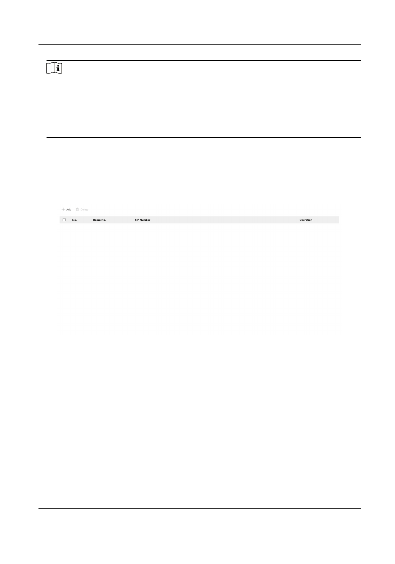
Number Sengs
Link the room No. and SIP numbers.
Click Number
Sengs to enter the page.
Figure 5-22 Number Sengs
Click Add, set the Room No. and SIP numbers in the pop-up dialog box.
5.3.10 Access Control
Sengs
Permission Password
Steps
1.
Click Access Control → Permission Password to enter the sengs page.
Module Door Staon User Manual
101
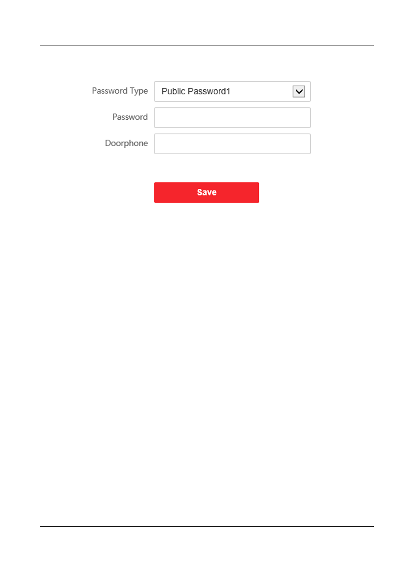
Figure 5-23 Permission Password
2.
Select the password type.
3.
Change the password.
4.
Set the number of doorphone.
5.
Click Save to enable the
sengs.
Door Parameters
Steps
1.
Click Access Control → Door Parameters to enter the
sengs page.
Module Door Staon User Manual
102
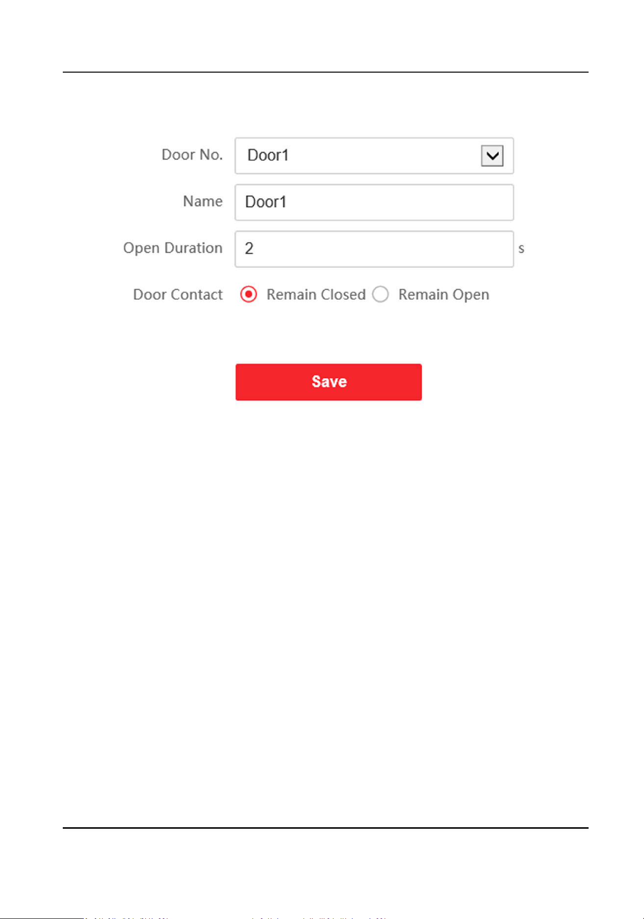
Figure 5-24 Door Parameters
2.
Select the door and edit the door name.
3.
Edit Open Duraon.
4.
Set door contact status.
5.
Click Save to enable the
sengs.
Card Security
Go to Access Control → Card Security to enter the sengs page.
Slide to enable card encrypon parameters and CPU card reading content. Click Save to enable the
sengs.
5.3.11 Theme
Sengs
Set the adversement on the main page of the device.
Steps
1.
Click Conguraon → Theme to enter the sengs page.
2.
Check to enable screen saving
funcon.
3.
Set the adversement theme.
1) Click + Add Theme.
Module Door Staon User Manual
103
2) Create a theme name, and select the adversement body as picture.
Note
●
The supported image format is .jpg. The upper-case .JPG is not supported.
●
The le name should contain only leers and digits with a length limit of 32 characters.
●
The maximum le size is 1 MB and the maximum resoluon is 3000*3000 px.
3) Click Save.
4.
Click + to select a picture from the local as the material to be played in standby, and click upload.
5.
Set the play schedule.
1) Select a theme and drag the
me interval to be played on the meline.
2) Oponal: Click the drawn area to edit the me manually.
3) Click Delete to delete the selected area. Click Delete All to delete all selected areas.
6.
Adjust Slide Show Interval.
Drag the block or enter the number to set the slide show interval. The picture will be changed
according to the interval.
7.
Oponal: Slide to enable show custom content and edit custom content.
The custom content displays on the main page of the device.
8.
Click Save.
5.4 Video Intercom
Sengs
The Video Intercom Management module provides the funcon of video intercom, checking call
logs and managing
noce via the iVMS-4200 Client Soware.
Note
For the user with access control module permissions, the user can enter the Access Control
module and manage video intercom and search informaon.
You should add the device to the soware and congure the person to link the device in Access
Control module before your
conguraon remotely.
On the main page, click AccessControlInfo → Video Intercom → Video Intercom on the le
bar to enter the Video Intercom page.
5.4.1 Receive Call from Door
Staon
Steps
1.
Select the client
soware in the page to start calling the client and an incoming call dialog will
pop up in the client soware.
2.
Click Answer to answer the call. Or click Hang Up to decline the call.
3.
Aer you answer the call, you will enter the In Call page.
Module Door Staon User Manual
104
Adjust the Volume of
Loudspeaker
Click to adjust the volume of loudspeaker.
Hang Up Click Hang Up to hang up.
Adjust the Volume of
Microphone
Click to adjust the volume of microphone.
Unlock Remotely For door staon, you can click to open the door
remotely.
Note
●
One video intercom device can only connect with one client soware.
●
The maximum ring duraon can be set from 15s to 60s via the Remote Conguraon of the
video intercom device.
●
The maximum speaking
duraon between indoor staon and iVMS-4200 can be set from 120s
to 600s via the Remote
Conguraon of indoor staon.
●
The maximum speaking duraon between door staon and iVMS-4200 can be set from 90s to
120s via the Remote Conguraon of door staon.
5.4.2 Search Call Logs
Steps
1.
On the Video Intercom page, click Call Log to enter the page.
Module Door Staon User Manual
105
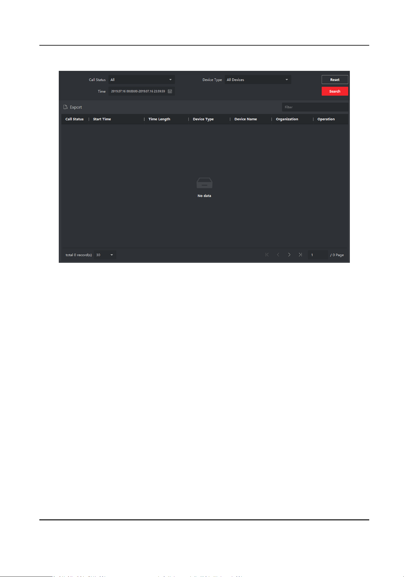
Figure 5-25 Search Call Logs
2.
Set the search condions, including call status, device type, start me and end me.
Call Status
Click ˅ to unfold the drop-down list and select the call status as Dialed, Received or Missed.
Or select All to search logs with all statuses.
Device Type
Click ˅ to unfold the drop-down list and select the device type as Indoor
Staon, Door
Staon, Outer Door Staon or Analog Indoor Staon. Or select All Devices to search logs
with all device types.
Start Time/End Time
Click the
me icon to specify the start me and end me of a me period to search the logs.
Reset the
Sengs Click Reset to reset all the congured search condions.
3.
Click Search and all the matched call logs will display on this page.
4.
Oponal: Check the detailed informaon of searched call logs, such as call status, ring/speaking
duraon, device name, resident organizaon, etc.
5.
Oponal: Input keywords in the Search eld to lter the desired log.
6.
Oponal: Click Export to export the call logs to your PC.
Module Door Staon User Manual
106
5.4.3 Upload Armed Informaon
Steps
1.
On the main page, click upper right
→ Tool → DeviceGuard to enter the page.
2.
Enable to arm or disarm the device.
Note
●
While device has been added to the client soware, the device armed by default.
●
When the device is armed, the alarm logs upload to the client soware automacally.
●
Click Alarm Applicaon → Event Search to search the alarm logs.
3.
Oponal: Click Arm All or Disarm All to arm or disarm all the device.
Module Door Staon User Manual
107
Appendix A. Communicaon Matrix and Device
Command
Communicaon Matrix
Scan the following QR code to get the device communicaon matrix.
Note that the matrix contains all
communicaon ports of Hikvision access control and video
intercom devices.
Figure A-1 QR Code of Communicaon Matrix
Device Command
Scan the following QR code to get the device common serial port commands.
Note that the command list contains all commonly used serial ports commands for all Hikvision
access control and video intercom devices.
Figure A-2 Device Command
Module Door Staon User Manual
108

UD29094B-A