
Video Intercom Analog Bundle
User Manual

Legal Informaon
©2021 Hangzhou Hikvision Digital Technology Co., Ltd. All rights reserved.
About this Manual
The Manual includes instrucons for using and managing the Product.
Pictures, charts, images and all other informaon hereinaer are for
descripon and explanaon only. The informaon contained in the Manual
is subject to change, without
noce, due to rmware updates or other
reasons. Please nd the latest version of this Manual at the Hikvision
website ( hps://www.hikvision.com/ ).
Please use this Manual with the guidance and assistance of professionals
trained in
supporng the Product.
Trademarks
and other Hikvision's trademarks and logos are the
properes of Hikvision in various jurisdicons.
Other trademarks and logos menoned are the properes of their
respecve owners.
Disclaimer
TO THE MAXIMUM EXTENT PERMITTED BY APPLICABLE LAW, THIS MANUAL
AND THE PRODUCT DESCRIBED, WITH ITS HARDWARE, SOFTWARE AND
FIRMWARE, ARE PROVIDED "AS IS" AND "WITH ALL FAULTS AND ERRORS".
HIKVISION MAKES NO WARRANTIES, EXPRESS OR IMPLIED, INCLUDING
WITHOUT LIMITATION, MERCHANTABILITY, SATISFACTORY QUALITY, OR
FITNESS FOR A PARTICULAR PURPOSE. THE USE OF THE PRODUCT BY YOU IS
AT YOUR OWN RISK. IN NO EVENT WILL HIKVISION BE LIABLE TO YOU FOR
ANY SPECIAL, CONSEQUENTIAL, INCIDENTAL, OR INDIRECT DAMAGES,
INCLUDING, AMONG OTHERS, DAMAGES FOR LOSS OF BUSINESS PROFITS,
BUSINESS INTERRUPTION, OR LOSS OF DATA, CORRUPTION OF SYSTEMS, OR
LOSS OF DOCUMENTATION, WHETHER BASED ON BREACH OF CONTRACT,
TORT (INCLUDING NEGLIGENCE), PRODUCT LIABILITY, OR OTHERWISE, IN
Video Intercom Analog Bundle User Manual
i

CONNECTION WITH THE USE OF THE PRODUCT, EVEN IF HIKVISION HAS
BEEN ADVISED OF THE POSSIBILITY OF SUCH DAMAGES OR LOSS.
YOU ACKNOWLEDGE THAT THE NATURE OF THE INTERNET PROVIDES FOR
INHERENT SECURITY RISKS, AND HIKVISION SHALL NOT TAKE ANY
RESPONSIBILITIES FOR ABNORMAL OPERATION, PRIVACY LEAKAGE OR
OTHER DAMAGES RESULTING FROM CYBER-ATTACK, HACKER ATTACK, VIRUS
INFECTION, OR OTHER INTERNET SECURITY RISKS; HOWEVER, HIKVISION
WILL PROVIDE TIMELY TECHNICAL SUPPORT IF REQUIRED.
YOU AGREE TO USE THIS PRODUCT IN COMPLIANCE WITH ALL APPLICABLE
LAWS, AND YOU ARE SOLELY RESPONSIBLE FOR ENSURING THAT YOUR USE
CONFORMS TO THE APPLICABLE LAW. ESPECIALLY, YOU ARE RESPONSIBLE,
FOR USING THIS PRODUCT IN A MANNER THAT DOES NOT INFRINGE ON THE
RIGHTS OF THIRD PARTIES, INCLUDING WITHOUT LIMITATION, RIGHTS OF
PUBLICITY, INTELLECTUAL PROPERTY RIGHTS, OR DATA PROTECTION AND
OTHER PRIVACY RIGHTS. YOU SHALL NOT USE THIS PRODUCT FOR ANY
PROHIBITED END-USES, INCLUDING THE DEVELOPMENT OR PRODUCTION
OF WEAPONS OF MASS DESTRUCTION, THE DEVELOPMENT OR
PRODUCTION OF CHEMICAL OR BIOLOGICAL WEAPONS, ANY ACTIVITIES IN
THE CONTEXT RELATED TO ANY NUCLEAR EXPLOSIVE OR UNSAFE NUCLEAR
FUEL-CYCLE, OR IN SUPPORT OF HUMAN RIGHTS ABUSES.
IN THE EVENT OF ANY CONFLICTS BETWEEN THIS MANUAL AND THE
APPLICABLE LAW, THE LATTER PREVAILS.
Data Protecon
During the use of device, personal data will be collected, stored and
processed. To protect data, the development of Hikvision devices
incorporates privacy by design principles. For example, for device with facial
recognion features, biometrics data is stored in your device with
encrypon method; for ngerprint device, only ngerprint template will be
saved, which is impossible to reconstruct a ngerprint image.
As data controller, you are advised to collect, store, process and transfer
data in accordance with the applicable data
protecon laws and regulaons,
including without limitaon, conducng security controls to safeguard
personal data, such as, implemenng reasonable administrave and
physical security controls, conduct periodic reviews and assessments of the
eecveness of your security controls.
Video Intercom Analog Bundle User Manual
ii
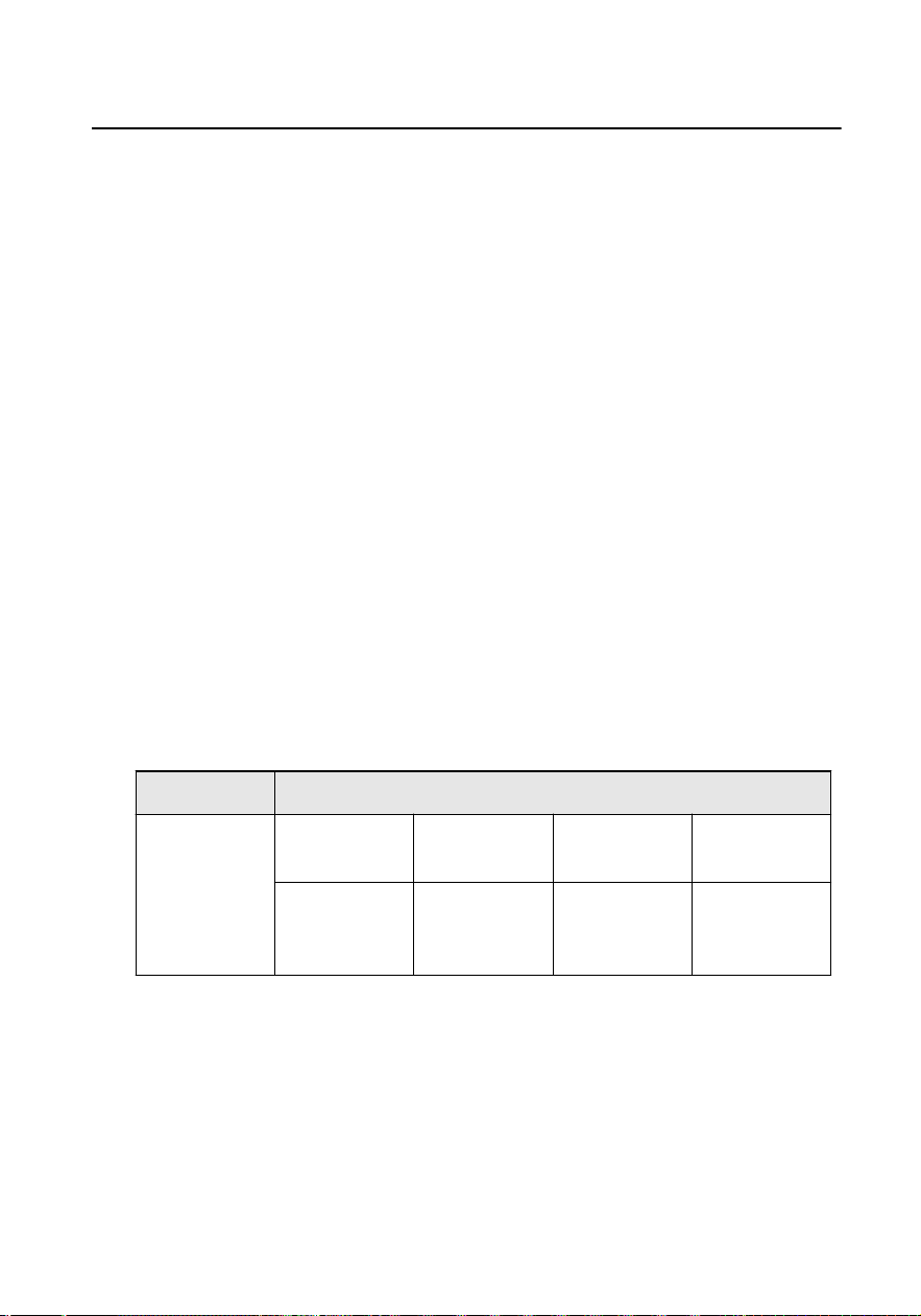
Symbol Convenons
The symbols that may be found in this document are dened as follows.
Symbol Descripon
Danger
Indicates a hazardous situaon which, if not avoided, will or
could result in death or serious injury.
Cauon
Indicates a potenally hazardous situaon which, if not
avoided, could result in equipment damage, data loss,
performance degradaon, or unexpected results.
Note
Provides addional informaon to emphasize or
supplement important points of the main text.
Video Intercom Analog Bundle User Manual
iii

Safety Instrucon
Warning
●
All the electronic operaon should be strictly compliance with the electrical safety
regulaons, re prevenon regulaons and other related regulaons in your local
region.
●
Please use the power adapter, which is provided by normal company. The power
consumpon cannot be less than the required value.
●
Do not connect several devices to one power adapter as adapter overload may
cause over-heat or re hazard.
●
Please make sure that the power has been disconnected before you wire, install or
dismantle the device.
●
When the product is installed on wall or ceiling, the device shall be
rmly xed.
●
If smoke, odors or noise rise from the device, turn
o the power at once and
unplug the power cable, and then please contact the service center.
●
If the product does not work properly, please contact your dealer or the nearest
service center. Never aempt to disassemble the device yourself. (We shall not
assume any responsibility for problems caused by unauthorized repair or
maintenance.)
Cauon
●
Do not drop the device or subject it to physical shock, and do not expose it to high
electromagnesm radiaon. Avoid the equipment installaon on vibraons
surface or places subject to shock (ignorance can cause equipment damage).
●
Do not place the device in extremely hot (refer to the specicaon of the device
for the detailed operang temperature), cold, dusty or damp locaons, and do not
expose it to high electromagnec radiaon.
●
The device cover for indoor use shall be kept from rain and moisture.
●
Exposing the equipment to direct sun light, low venlaon or heat source such as
heater or radiator is forbidden (ignorance can cause
re danger).
●
Do not aim the device at the sun or extra bright places. A blooming or smear may
occur otherwise (which is not a malfuncon however), and aecng the
endurance of sensor at the same me.
Video Intercom Analog Bundle User Manual
iv
●
Please use the provided glove when open up the device cover, avoid direct contact
with the device cover, because the acidic sweat of the ngers may erode the
surface coang of the device cover.
●
Please use a so and dry cloth when clean inside and outside surfaces of the
device cover, do not use alkaline detergents.
●
Please keep all wrappers aer unpack them for future use. In case of any failure
occurred, you need to return the device to the factory with the original wrapper.
Transportaon without the original wrapper may result in damage on the device
and lead to
addional costs.
●
Improper use or replacement of the baery may result in hazard of explosion.
Replace with the same or equivalent type only. Dispose of used baeries
according to the instrucons provided by the baery manufacturer.
●
Input voltage should meet both the SELV and the Limited Power Source according
to 60950-1 standard.
●
The power supply must conform to LPS. The recommended adaptor models and
manufacturers are shown as below. Use the aached adapter, and do not change
the adaptor randomly.
Model Manufacturer Standard
ADS-24S-12 1224GPCN SHENZHEN HONOR
ELECTRONIC CO.,LTD
CEE
G0549-240-050 SHENZHEN GOSPELL DIGITAL
TECHNOLOGY CO.,LTD
CEE
TS-A018-120015Ec SHENZHEN TRANSIN
TECHNOLOGIES CO., LTD
CEE
Video Intercom Analog Bundle User Manual
v

Regulatory Informaon
FCC Informaon
Please take aenon that changes or modicaon not expressly approved
by the party responsible for compliance could void the user's authority to
operate the equipment.
FCC compliance: This equipment has been tested and found to comply with
the limits for a Class B digital device, pursuant to part 15 of the FCC Rules.
These limits are designed to provide reasonable protecon against harmful
interference in a residenal installaon. This equipment generates, uses and
can radiate radio frequency energy and, if not installed and used in
accordance with the instrucons, may cause harmful interference to radio
communicaons. However, there is no guarantee that interference will not
occur in a parcular installaon. If this equipment does cause harmful
interference to radio or television recepon, which can be determined by
turning the equipment o and on, the user is encouraged to try to correct
the interference by one or more of the following measures:
—Reorient or relocate the receiving antenna.
—Increase the separaon between the equipment and receiver.
—Connect the equipment into an outlet on a circuit dierent from that to
which the receiver is connected.
—Consult the dealer or an experienced radio/TV technician for help
This equipment should be installed and operated with a minimum distance
20cm between the radiator and your body.
FCC
Condions
This device complies with part 15 of the FCC Rules. Operaon is subject to
the following two condions:
1. This device may not cause harmful interference.
2. This device must accept any interference received, including interference
that may cause undesired
operaon.
Video Intercom Analog Bundle User Manual
vi
EU Conformity Statement
This product and - if applicable - the supplied accessories too are
marked with "CE" and comply therefore with the applicable
harmonized European standards listed under the EMC Direcve
2014/30/EU, RE Direcve 2014/53/EU,the RoHS Direcve 2011/
65/EU
2012/19/EU (WEEE direcve): Products marked with this symbol
cannot be disposed of as unsorted municipal waste in the
European Union. For proper recycling, return this product to your
local supplier upon the purchase of equivalent new equipment, or
dispose of it at designated collecon points. For more informaon
see: www.recyclethis.info
2006/66/EC (baery direcve): This product contains a baery
that cannot be disposed of as unsorted municipal waste in the
European Union. See the product documentaon for specic
baery informaon. The baery is marked with this symbol,
which may include leering to indicate cadmium (Cd), lead (Pb),
or mercury (Hg). For proper recycling, return the
baery to your
supplier or to a designated collecon point. For more informaon
see:www.recyclethis.info
Industry Canada ICES-003 Compliance
This device meets the CAN ICES-3 (B)/NMB-3(B) standards requirements.
This device complies with Industry Canada licence-exempt RSS standard(s).
Operaon is subject to the following two condions:
1.
this device may not cause interference, and
2.
this device must accept any interference, including interference that may
cause undesired operaon of the device.
Le présent appareil est conforme aux CNR d'Industrie Canada applicables
aux appareils radioexempts de licence. L'exploitaon est autorisée aux deux
condions suivantes :
Video Intercom Analog Bundle User Manual
vii

1.
l'appareil ne doit pas produire de brouillage, et
2.
l'ulisateur de l'appareil doit accepter tout brouillage radioélectrique
subi, même si le brouillage est suscepble d'en compromere le
fonconnement.
Under Industry Canada regulaons, this radio transmier may only operate
using an antenna of a type and maximum (or lesser) gain approved for the
transmier by Industry Canada. To reduce potenal radio interference to
other users, the antenna type and its gain should be so chosen that the
equivalent isotropically radiated power (e.i.r.p.) is not more than that
necessary for successful communicaon.
Conformément à la réglementaon d'Industrie Canada, le présent émeeur
radio peut fonconner avec une antenne d'un type et d'un gain maximal (ou
inférieur) approuvé pour l'émeeur par Industrie Canada. Dans le but de
réduire les risques de brouillage radioélectrique à l'intenon des autres
ulisateurs, il faut choisir le type d'antenne et son gain de sorte que la
puissance isotrope rayonnée équivalente (p.i.r.e.) ne dépasse pas l'intensité
nécessaire à l'établissement d'une communicaon sasfaisante.
This equipment should be installed and operated with a minimum distance
20cm between the radiator and your body.
Cet équipement doit être installé et
ulisé à une distance minimale de 20
cm entre le radiateur et votre corps.
Video Intercom Analog Bundle User Manual
viii

Contents
1 About this Maunal ...................................................................................... 1
2 Appearance Descripon ............................................................................. 2
2.1 Appearance of Door Staon .............................................................................. 2
2.2 Appearance of Indoor Staon ........................................................................... 3
3 Terminal and Wiring Descripon ................................................................ 5
3.1 Terminal Descripon ......................................................................................... 5
3.2 Wiring Descripon ............................................................................................ 7
3.2.1 Door Lock Wiring ...................................................................................... 7
3.2.2 Door Contact Wiring ................................................................................. 9
3.2.3 Exit
Buon Wiring .................................................................................. 10
3.3 Typical Applicaon .......................................................................................... 11
4 Installaon ................................................................................................ 13
4.1 Door Staon Installaon ................................................................................. 13
4.1.1 DIP Switch Sengs ................................................................................. 13
4.1.2 Accessory Introducon ........................................................................... 14
4.1.3 Surface Mounng without Gang Box ..................................................... 16
4.1.4 Flush Mounng with Juncon Box ......................................................... 17
4.1.5 Flush Mounng with Gang Box(Type I) ................................................... 18
4.1.6 Flush Mounng with Gang Box(Type II) .................................................. 19
4.2 Indoor Staon Installaon .............................................................................. 20
4.2.1 Congure Ringtone ................................................................................. 20
4.2.2 Wall Mounng ........................................................................................ 21
Video Intercom Analog Bundle User Manual
ix

5 Local Operaon ........................................................................................ 24
A. Cables ...................................................................................................... 26
B. Communicaon Matrix and Device Command ....................................... 28
Video Intercom Analog Bundle User Manual
x
2 Appearance Descripon
2.1 Appearance of Door Staon
Figure 2-1 Appearance
Table 2-1
Descripon
No. Descripon No. Descripon
1 Camera 6 Terminals
2 Loudspeaker 7 Debugging Port
3 Call Buon 8 DIP Switch
4 Microphone 9 Screw for Volume
Adjustment
5 TAMPER
Note
The debugging port is used for debugging only.
Video Intercom Analog Bundle User Manual
2
2.2 Appearance of Indoor Staon
Front Panel
Figure 2-2 Front Panel
Table 2-2
Descripon
No. Descripon No. Descripon
1 Screen 5 Receive/Decline
2 Microphone 6 Unlock Door 2
3 Volume- 7 Unlock Door 1
4 Volume+ 8 View/Switch
Video Intercom Analog Bundle User Manual
3
Rear Panel
Figure 2-3 Rear Panel
Table 2-3
Descripon
No. Descripon No. Descripon
9 Terminals 12 DIP Switch
10 Loudspeaker 13 Debugging Port
11 Power Supply Terminal
Note
●
The appearance of the device varies according to dierent models. Refers
to the actual device for detailed informaon.
●
The debugging port is used for debugging only.
Video Intercom Analog Bundle User Manual
4
3 Terminal and Wiring Descripon
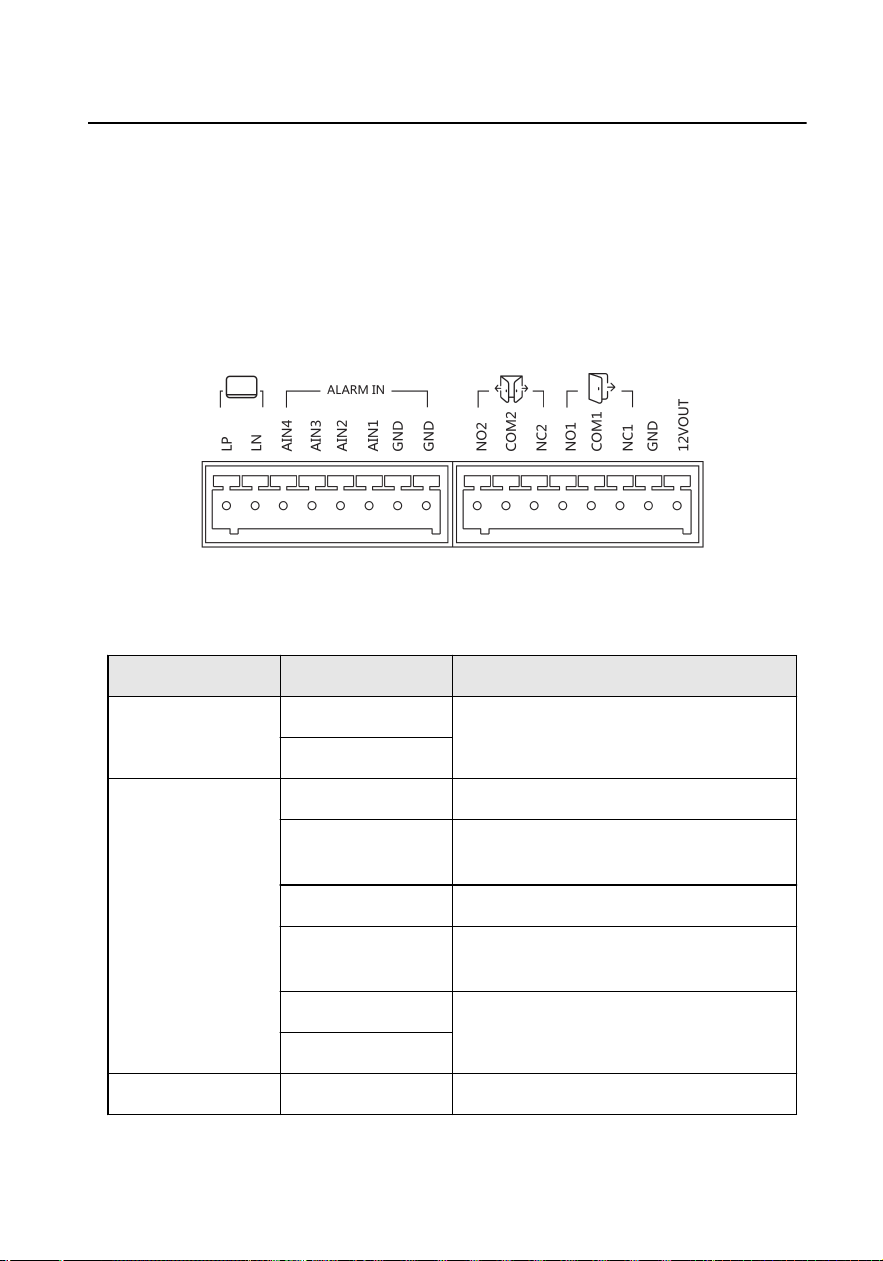
3.1 Terminal Descripon
Terminal of Door Staon
Figure 3-1 Terminal Descripon
Table 3-1 Terminal of Door Staon
Type Name Descripon
Cascade LP For the access of Indoor Staon
LN
ALARM IN AIN1 For the access of Exit Buon of Door 1.
AIN2 For the access of Door Contact of Door
1.
AIN3 For the access of Exit Buon of Door 2.
AIN4 For the access of Door Contact of Door
2.
GND Grounding
GND
Door Lock NO1 For the access of Door Lock 1
Video Intercom Analog Bundle User Manual
5
Type Name Descripon
NC1
COM1
NO2 For the access of Door Lock 2
NC2
COM2
Power Output 12VOUT 12 VDC output
GND Grounding
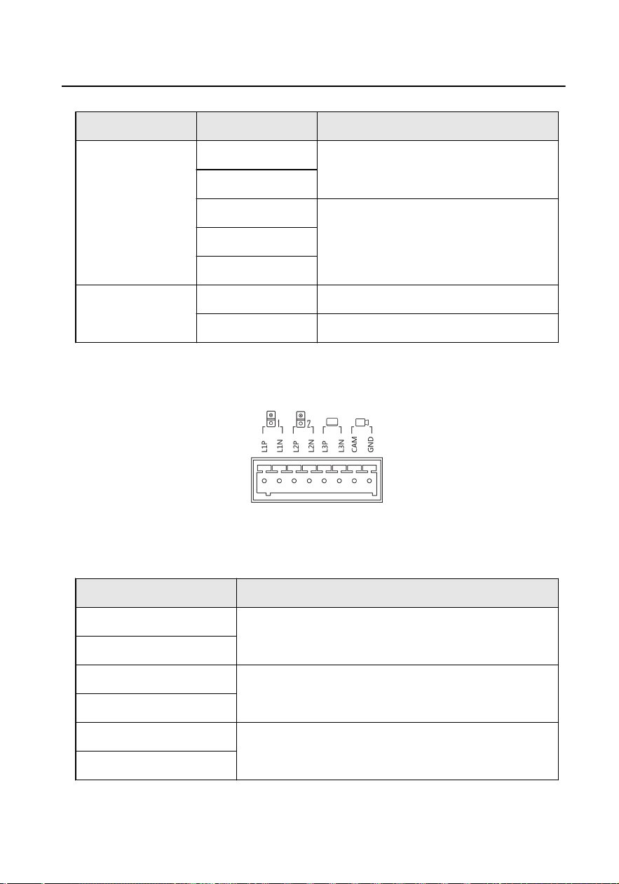
Terminal of Indoor Staon
Figure 3-2 Terminal Descripon
Table 3-2 Terminal of Indoor Staon
Name Descripon
L1P For the access of Doorbell 1.
L1N
L2P For the access of Doorbell 2.
L2N
L3P For the access of Door Staon (DS-KV1101-ME2)/
Indoor Staon (DS-KH1200).
L3N
Video Intercom Analog Bundle User Manual
6
Name Descripon
Note
●
This terminal of the indoor staon supports
connecng to the main door staon.
●
This terminal of the indoor staon supports
cascade connecng to other indoor staons.
CAM For the access of Camera
GND
3.2 Wiring Descripon
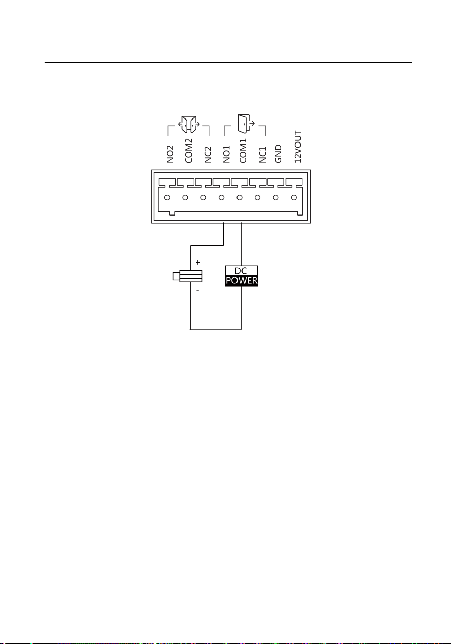
3.2.1 Door Lock Wiring
Up to 2 door locks can be connected to the door staon. You can unlock the door
lock remotely via indoor staon when you connected the door lock.
Note
Terminal NC/COM is set as default for accessing magnec lock/electric bolt; terminal
NO/COM is set as default for accessing electric strike.
Video Intercom Analog Bundle User Manual
7
Electric Strike Wiring
Figure 3-3 Electric Strike Wiring
Video Intercom Analog Bundle User Manual
8
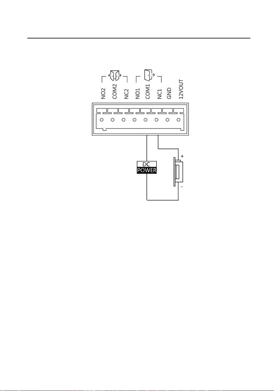
Magnec Lock Wiring
Figure 3-4 Magnec Lock Wiring
3.2.2 Door Contact Wiring
AIN2 and AIN4 are used to connect door contact. AIN2 is used to connect door
contact of the door 1. AIN4 is used to connect door contact of the door 2.
Here takes door contact wiring with AIN2 for example.
Video Intercom Analog Bundle User Manual
9
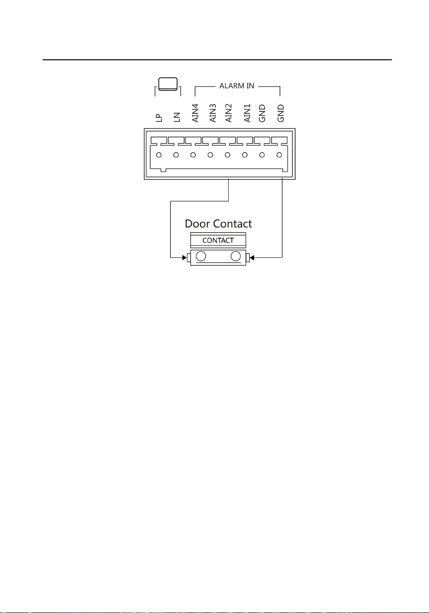
Figure 3-5 Door Contact Wiring
3.2.3 Exit Buon Wiring
AIN1 and AIN3 are used to connect door contact. AIN1 is used to connect door
contact of the door 1. AIN3 is used to connect door contact of the door 2.
Here takes door contact wiring with AIN1 for example.
Video Intercom Analog Bundle User Manual
10
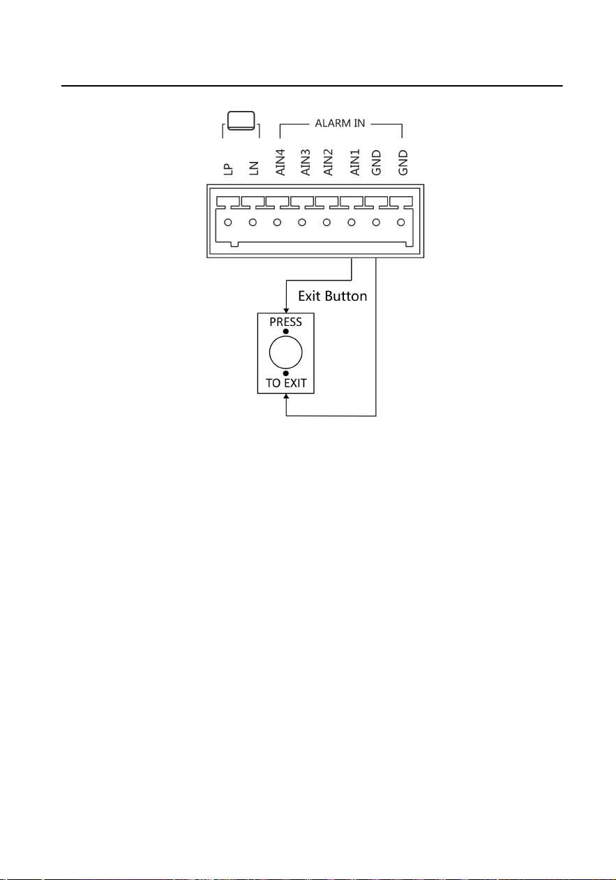
Figure 3-6 Exit Buon Wiring
3.3 Typical
Applicaon
The typical applicaon is shown as below.
Up to 2 door staons can be connected to the indoor staon.
Support up to two-three hand in hand topology.
Video Intercom Analog Bundle User Manual
11
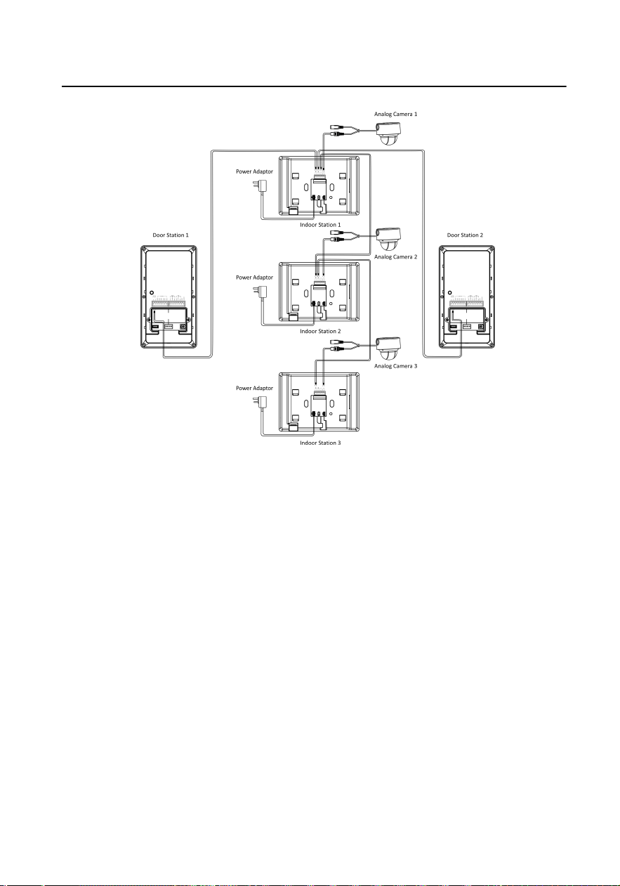
Figure 3-7 Typical Applicaon
Video Intercom Analog Bundle User Manual
12
4 Installaon
4.1 Door Staon Installaon
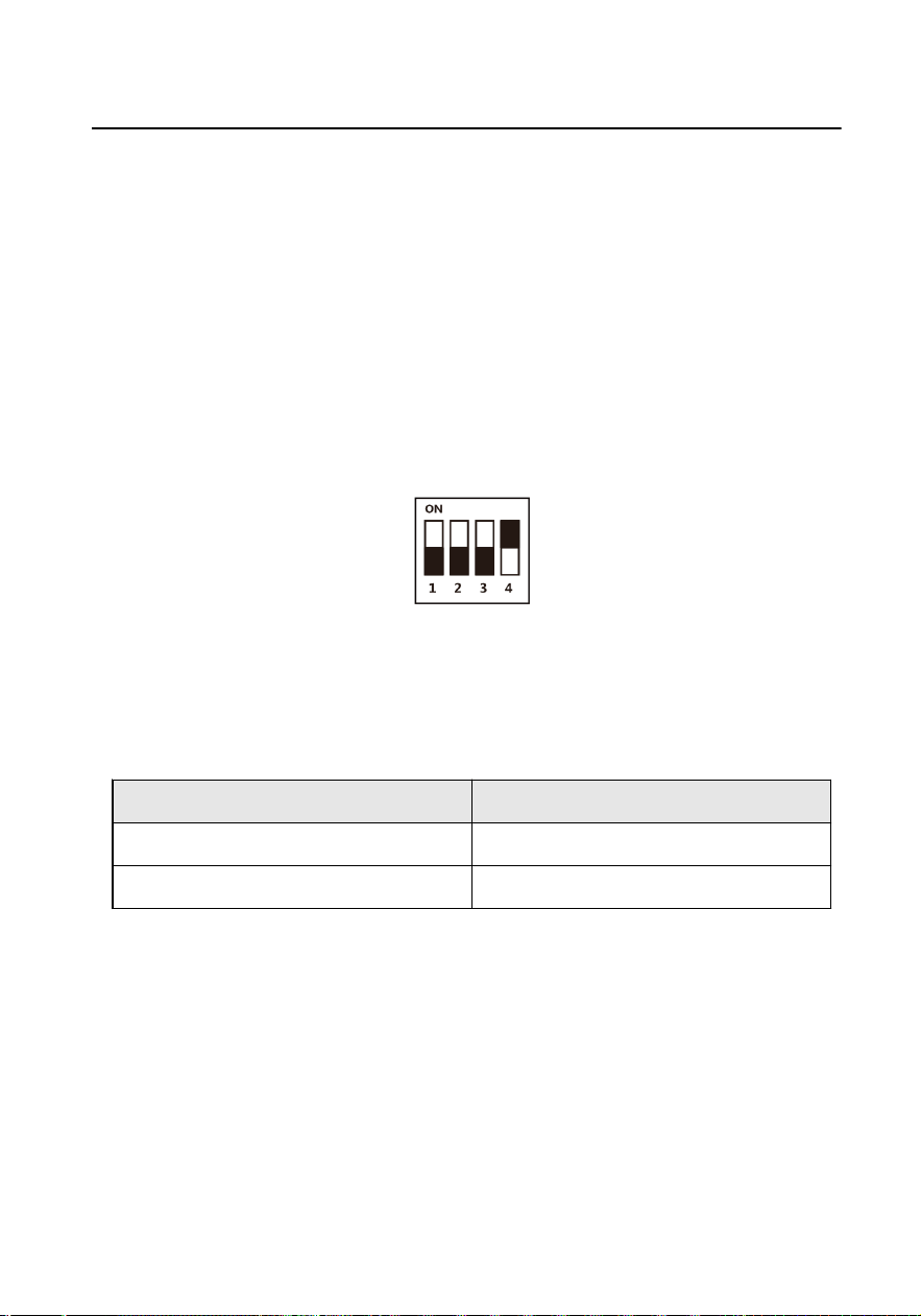
4.1.1 DIP Switch Sengs
DIP switch 1 is used to coding the room No. of door staon. The No. should be
unique.
DIP switch 2,3,4 are used to coding the unlock
duraon of the door staon.
Figure 4-1 DIP Switch
The
relaonship between address of door staon and DIP switches is shown as
below.
Table 4-1 Door
Staon Address
DIP 1 Address
OFF 1
ON 2
The relaonship between unlock duraon and DIP switches is shown as below.
Video Intercom Analog Bundle User Manual
13

Table 4-2 Unlock Duraon
Unlock
Dura
on(s)
1 2 3 4 5 6 7 8
DIP2 OFF ON OFF ON OFF ON OFF ON
DIP3 OFF OFF ON ON OFF OFF ON ON
DIP4 OFF OFF OFF OFF ON ON ON ON
4.1.2 Accessory Introducon
The installaon of door staon needs accessories, including juncon box, gang box
(Type I & Type II),
mounng plate and so on.
There are 2 size of the gang boxes adapted to the device.
●
Size 1: 75 mm (width) × 75 mm (length) × 46 mm (depth).
●
Size 2: 55 mm (width) × 101 mm (length) × 38.5 mm (depth).
Mounng Plate
The dimension of mounng plate is 82.87 mm × 142 mm × 43.38 mm.
Video Intercom Analog Bundle User Manual
14
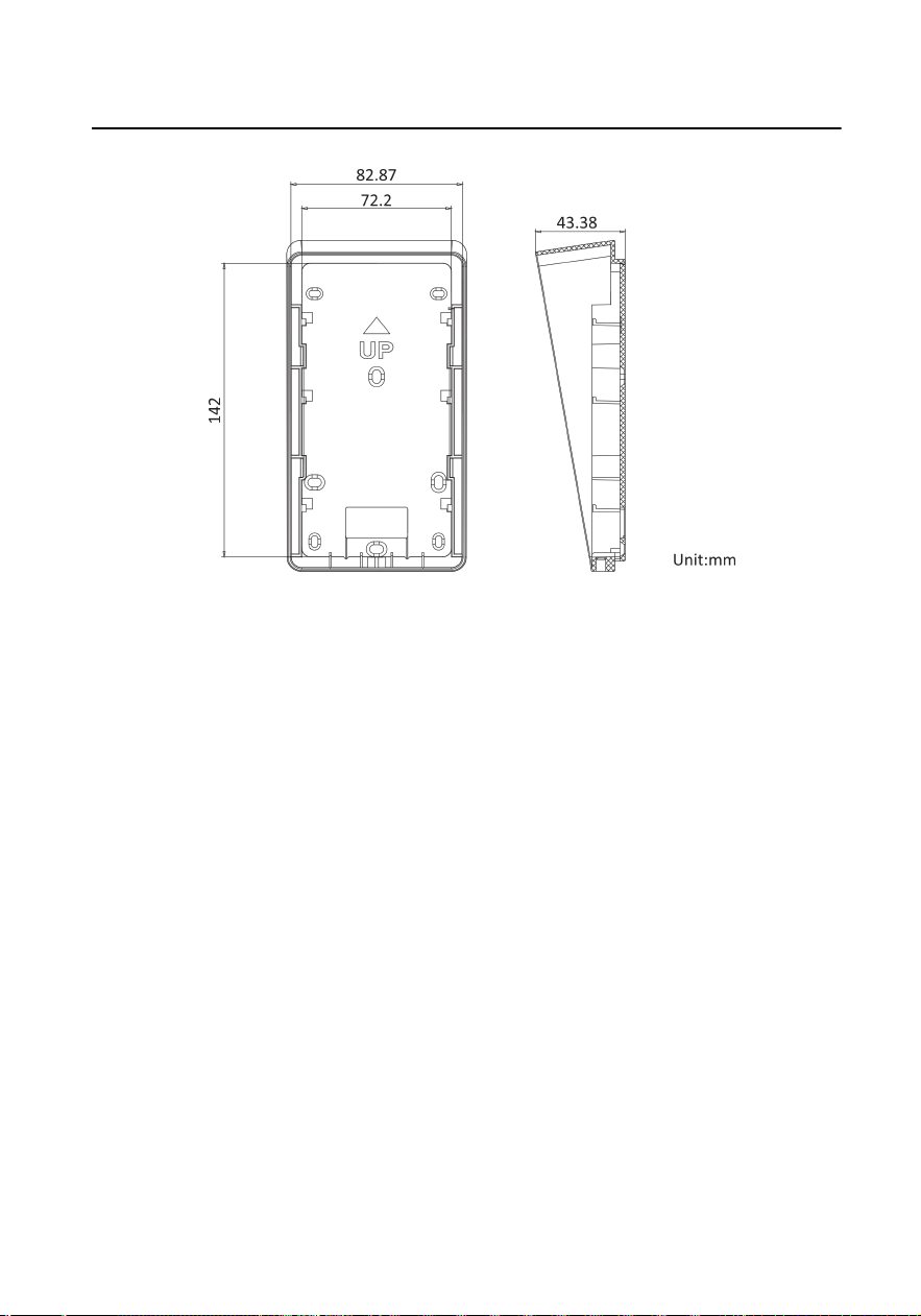
Figure 4-2 Mounng Plate
Juncon Box
The dimension of juncon box is 86.7 mm × 159.91 mm × 53.59 mm.
Video Intercom Analog Bundle User Manual
15
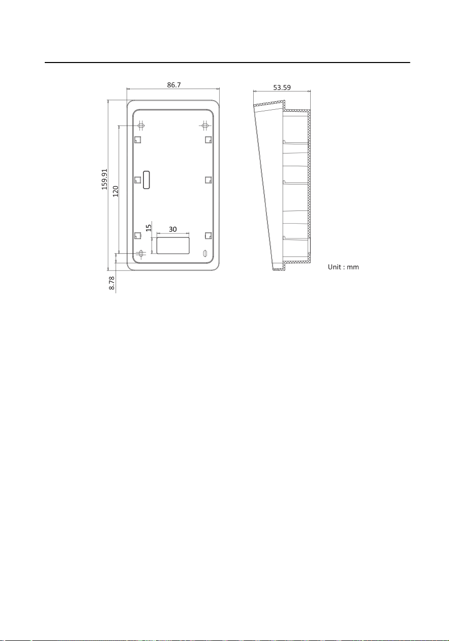
Figure 4-3 Juncon Box
4.1.3 Surface Mounng without Gang Box
Video intercom villa door staon supports surface mounng.
Before You Start
●
Make sure all related equipments are power-o during the installaon.
●
Accessories that you need to prepare for installaon: Mounng plate and
mounng template.
●
Tools that you need to prepare for installaon: Drill (ø2.846) and gradienter.
●
Purchase the
protecve shield before installaon.
Steps
1. Sck the mounng template on the wall. Drill the screw holes according to the
mounng template. Remove the mounng template from the wall.
2. Align and secure the mounng plate on the wall with 4 supplied screws according
to the screw holes.
3. Install the door staon to the mounng plate. Fix the device on the mounng
plate with the set screw.
Video Intercom Analog Bundle User Manual
16
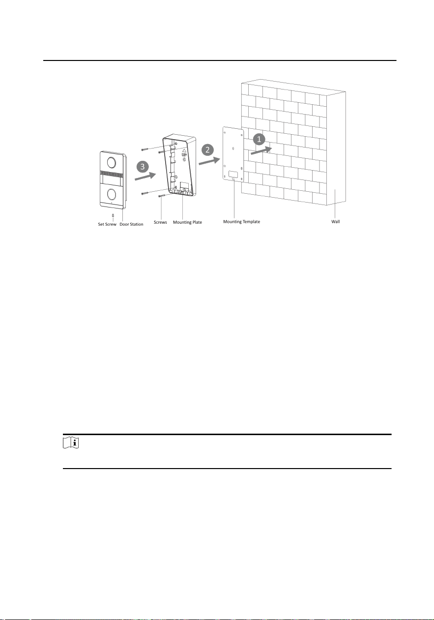
Figure 4-4 Surface Mounng without Gang Box
4.1.4 Flush Mounng with Juncon Box
The device supports ush mounng with juncon box.
Before You Start
●
Make sure all related equipments are
power-o during the installaon.
●
Accessories that you need to prepare for installaon: Juncon box and mounng
template.
●
Tools that you need to prepare for
installaon: Drill (ø2.846) and gradienter.
●
Purchase the protecve shield before installaon.
Steps
1. Cave the installaon hole and pull the cable out.
Note
The dimension of the installaon hole should be larger than the juncon box.
2. Sck the mounng template into the installaon hole.
3. Insert the juncon box into the hole and x it with 4 screws according to the
screw holes.
4. Insert the door
staon into the juncon box, and x it with set screw.
Video Intercom Analog Bundle User Manual
17
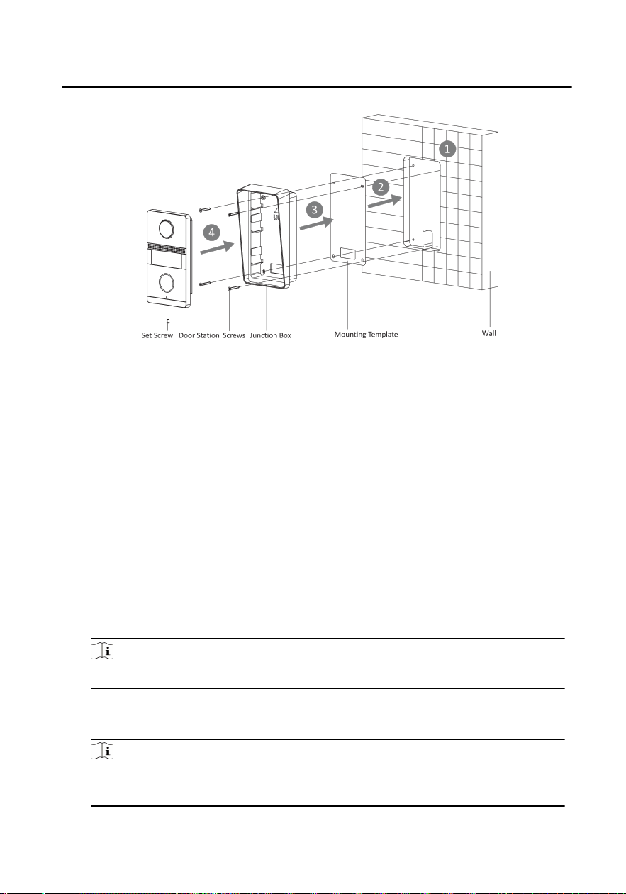
Figure 4-5 Flush Mounng with Juncon Box
4.1.5 Flush Mounng with Gang Box(Type I)
The device supports ush mounng with gang box.
Before You Start
●
Make sure all related equipments are
power-o during the installaon.
●
Accessories that you need to prepare for
installaon: Gang box and mounng
plate.
●
Tools that you need to prepare for
installaon: Drill (ø2.846) and gradienter.
●
Purchase the protecve shield before installaon.
Steps
1. Cave the installaon hole in the wall.
Note
The dimension of the installaon hole should be larger than the gang box.
2. Insert the gang box to the hole chiseled on the wall.
3. Fix the
mounng plate to the gang box with 2 screws.
Note
The dimension of the gang box is 75mm(width) × 75 mm(length) × 46 mm(depth),
the le and right holes will be applies.
Video Intercom Analog Bundle User Manual
18

4. Secure the door staon to the mounng plate with the set screw.
Figure 4-6 Flush Mounng with Gang Box (Type I)
4.1.6 Flush Mounng with Gang Box(Type II)
The device supports ush mounng with gang box.
Before You Start
●
Make sure all related equipments are
power-o during the installaon.
●
Accessories that you need to prepare for installaon: Gang box and mounng
plate.
●
Tools that you need to prepare for installaon: Drill (ø2.846) and gradienter.
●
Purchase the
protecve shield before installaon.
Steps
1. Cave the
installaon hole in the wall.
Note
The dimension of the installaon hole should be larger than the gang box.
2. Insert the gang box to the hole chiseled on the wall.
3. Fix the mounng plate to the gang box with 2 screws.
Note
The dimension of the gang box is 55mm(width) × 101 mm(length) × 38.5
mm(depth), the upper and lower holes will be applies.
4. Secure the door staon to the mounng plate with the set screw.
Video Intercom Analog Bundle User Manual
19
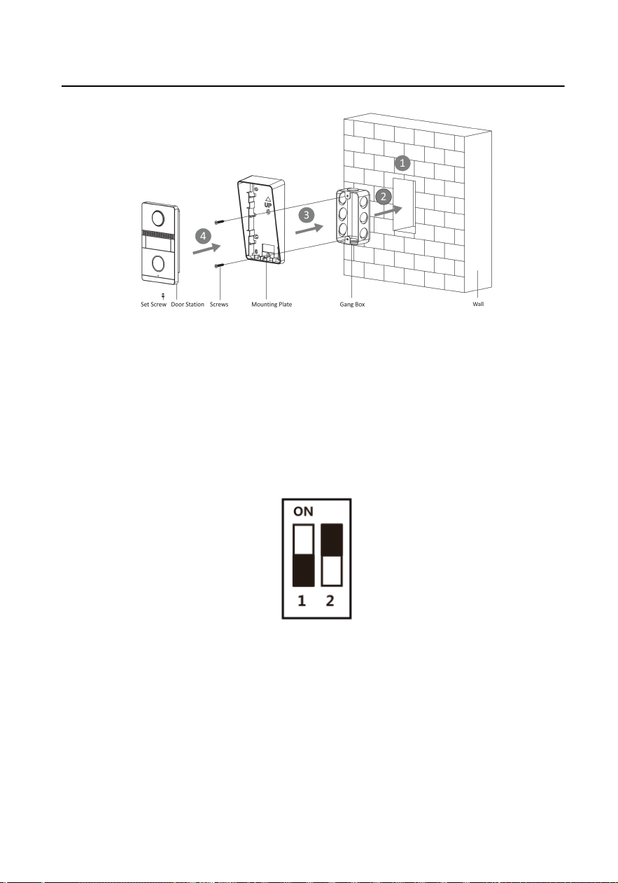
Figure 4-7 Flush Mounng with Gang Box (Type II)
4.2 Indoor
Staon Installaon
4.2.1 Congure Ringtone
DIP switch 1 and 2 are used to coding the ringtone of the indoor staon.
Figure 4-8 DIP Switch
The relaonship between the ringtone and DIP switches is shown as below.
Video Intercom Analog Bundle User Manual
20

Table 4-3 Ringtone
Ringtone DIP 1 DIP 2
Ringtone 1 OFF OFF
Ringtone 2 ON OFF
Ringtone 3 OFF ON
Mute ON ON
4.2.2 Wall Mounng
It supports wall mounng. There are two installaon modes.
Before You Start
●
Make sure the device in the package is in good
condion and all the assembly
parts are included.
●
The power supply the indoor staon supports is 48 VDC. Please make sure your
power supply matches your indoor staon.
●
Make sure all related equipments are power-o during the installaon.
●
Check the product specicaon for the installaon environment.
There are 2 size of the gang boxes adapted to the device.
●
Size 1: 75 mm (width) × 75 mm (length) × 50 mm (depth).
●
Size 2: 55 mm (width) × 101 mm (length) × 38.5 mm (depth).
The dimension of
mounng plate is shown as below.
Video Intercom Analog Bundle User Manual
21
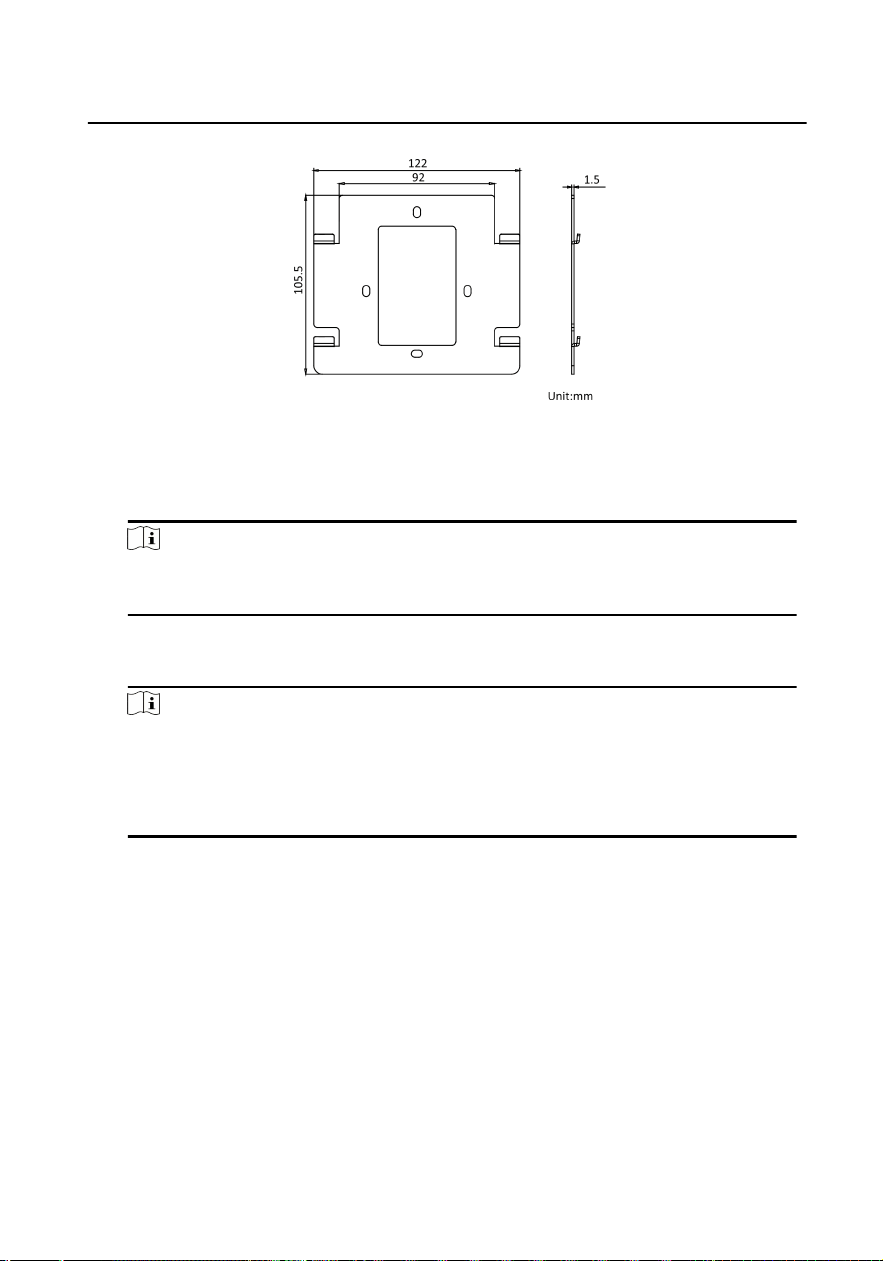
Figure 4-9 Mounng Plate
Steps
1. Cave a hole in the wall.
Note
The suggested dimension fo the installaon hole should be larger than the gang
box.
2. Insert a gang box to the hole chiseled on the wall.
3. Fix the wall mounng plate to the gang box with 2 screws.
Note
●
If you install the device with a gang box (75 mm(width) × 75 mm(length) × 46
mm(depth)), the le and right holes will be applied.
●
If you install the device with a gang box (55 mm(width) × 101 mm(length) × 48.5
mm(depth)), the upper and lower holes will be applied.
4. Hook the indoor staon to the wall mounng plate ghtly by inserng the plate
hooks into the slots on the rear panel of the indoor staon, during which the lock
catch will be locked automacally.
Video Intercom Analog Bundle User Manual
22
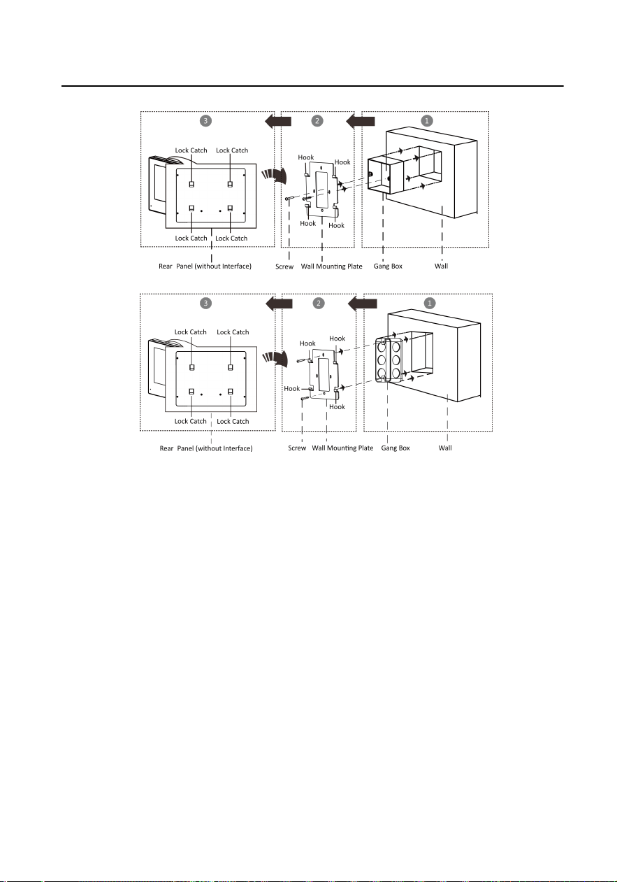
Figure 4-10 Wall Mounng
Video Intercom Analog Bundle User Manual
23
5 Local Operaon
Communicaon
You can call the resident by pressing the call buon on the door staon.
Press the call buon of the door staon, all linked indoor staon start
ringing.
Note
While one of linked indoor staons receive the call, the others will stop
ringing.
When indoor staon receive the call from door staon, tap Receive/Decline
buon on the indoor staon to accept the call and tap Receive/Decline
buon again to hang up the call.
Unlock
You can tap Unlock Door 1 buon on the indoor staon to unlock the door 1
when
communicang with the door staon or outer door staon.
You can tap Unlock Door 2 buon on the indoor staon to unlock the door 2
when communicang with the door staon or outer door staon.
Live View
Tap View/Switch buon on the indoor staon to start live viewing the door
staon. And tap View/Switch buon to exit.
Note
Indoor staon only supports view the main door staon.
Volume Adjustment
Tap Volume+ buon on the indoor staon to turn up the volume of indoor
staon.
Video Intercom Analog Bundle User Manual
24

Tap Volume- buon on the indoor staon to turn down the volume of
indoor staon.
Video Intercom Analog Bundle User Manual
25
A. Cables
Cables and Wiring
●
When there are mulple cores in one parallel line, only one pair of closed
cores are allowed to transmit signal. It is not allowed to use mulple pair
of cores in one cable to transmit signal.
●
When using parallel lines, it is suggested to use those with shielding layer.
If dual core or mulple core parallel lines without shielding layer are
routed, stability of signal transmission can be eected. You need to run a
test before installaon.
●
Impedance of cable should not be over suggested value, or distributor
cannot transmit enough power to indoor staon or door staon.
●
Strong electricity and weak electricity cannot be wired in the same route,
they need to be wired separately and the distance should be more than
0.5 meter.
●
All the cables used need to follow the
restricon in the following table.
Table A-1 Wiring Cables A
Roung Path Twisted Pair
Door Staon-
Indoor Staon
24AWG (0.2
mm
2
)
20AWG (0.5
mm
2
)
18AWG (0.8
mm
2
)
16AWG (1
mm
2
)
Transmission
Distance ≤ 70
m
Transmission
Distance ≤
100 m
Transmission
Distance ≤
100 m
Transmission
Distance ≤
100 m
Video Intercom Analog Bundle User Manual
26

Table A-2 Wiring Cables B
Roung Path Parallel lines
Door Staon-
Indoor Staon
24AWG (0.2
mm
2
)
20AWG (0.5
mm
2
)
18AWG (0.8
mm
2
)
16AWG (1
mm
2
)
Transmission
Distance ≤ 50
m
Transmission
Distance ≤
100 m
Transmission
Distance ≤
100 m
Transmission
Distance ≤
100 m
Device Installaon
●
Installaon environment (temperature, moisture etc.) need to follow
requirements in specicaon or power output can be eected.
●
Power consumpon of modular door staon (main module and sub
modules) should be less than 12W. Please reach local technical support if
you are not sure about power consumpon of each module. Door staon
should be connected to CH1 of the video/audio distributor.
●
Power supply must be cered by Hikvision.
Video Intercom Analog Bundle User Manual
27

B. Communicaon Matrix and Device
Command
Communicaon Matrix
Scan the following QR code to get the device communicaon matrix.
Note that the matrix contains all communicaon ports of Hikvision access
control and video intercom devices.
Figure B-1 QR Code of Communicaon Matrix
Device Command
Scan the following QR code to get the device common serial port
commands.
Note that the command list contains all commonly used serial ports
commands for all Hikvision access control and video intercom devices.
Figure B-2 Device Command
Video Intercom Analog Bundle User Manual
28

UD28777B
