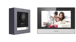

Video Intercom Kit
User Manual

Legal Informaon
©2023 Hangzhou Hikvision Digital Technology Co., Ltd. All rights reserved.
About this Manual
The Manual includes instrucons for using and managing the Product. Pictures, charts, images and
all other informaon hereinaer are for descripon and explanaon only. The informaon
contained in the Manual is subject to change, without noce, due to rmware updates or other
reasons. Please nd the latest version of this Manual at the Hikvision website ( hps://
www.hikvision.com/ ).
Please use this Manual with the guidance and assistance of professionals trained in supporng the
Product.
Trademarks
and other Hikvision's trademarks and logos are the properes of
Hikvision in various jurisdicons.
Other trademarks and logos menoned are the properes of their respecve owners.
Disclaimer
TO THE MAXIMUM EXTENT PERMITTED BY APPLICABLE LAW, THIS MANUAL AND THE PRODUCT
DESCRIBED, WITH ITS HARDWARE, SOFTWARE AND FIRMWARE, ARE PROVIDED "AS IS" AND "WITH
ALL FAULTS AND ERRORS". HIKVISION MAKES NO WARRANTIES, EXPRESS OR IMPLIED, INCLUDING
WITHOUT LIMITATION, MERCHANTABILITY, SATISFACTORY QUALITY, OR FITNESS FOR A PARTICULAR
PURPOSE. THE USE OF THE PRODUCT BY YOU IS AT YOUR OWN RISK. IN NO EVENT WILL HIKVISION
BE LIABLE TO YOU FOR ANY SPECIAL, CONSEQUENTIAL, INCIDENTAL, OR INDIRECT DAMAGES,
INCLUDING, AMONG OTHERS, DAMAGES FOR LOSS OF BUSINESS PROFITS, BUSINESS
INTERRUPTION, OR LOSS OF DATA, CORRUPTION OF SYSTEMS, OR LOSS OF DOCUMENTATION,
WHETHER BASED ON BREACH OF CONTRACT, TORT (INCLUDING NEGLIGENCE), PRODUCT LIABILITY,
OR OTHERWISE, IN CONNECTION WITH THE USE OF THE PRODUCT, EVEN IF HIKVISION HAS BEEN
ADVISED OF THE POSSIBILITY OF SUCH DAMAGES OR LOSS.
YOU ACKNOWLEDGE THAT THE NATURE OF THE INTERNET PROVIDES FOR INHERENT SECURITY
RISKS, AND HIKVISION SHALL NOT TAKE ANY RESPONSIBILITIES FOR ABNORMAL OPERATION,
PRIVACY LEAKAGE OR OTHER DAMAGES RESULTING FROM CYBER-ATTACK, HACKER ATTACK, VIRUS
INFECTION, OR OTHER INTERNET SECURITY RISKS; HOWEVER, HIKVISION WILL PROVIDE TIMELY
TECHNICAL SUPPORT IF REQUIRED.
YOU AGREE TO USE THIS PRODUCT IN COMPLIANCE WITH ALL APPLICABLE LAWS, AND YOU ARE
SOLELY RESPONSIBLE FOR ENSURING THAT YOUR USE CONFORMS TO THE APPLICABLE LAW.
ESPECIALLY, YOU ARE RESPONSIBLE, FOR USING THIS PRODUCT IN A MANNER THAT DOES NOT
INFRINGE ON THE RIGHTS OF THIRD PARTIES, INCLUDING WITHOUT LIMITATION, RIGHTS OF
PUBLICITY, INTELLECTUAL PROPERTY RIGHTS, OR DATA PROTECTION AND OTHER PRIVACY RIGHTS.
YOU SHALL NOT USE THIS PRODUCT FOR ANY PROHIBITED END-USES, INCLUDING THE
Video Intercom Kit User Manual
i

DEVELOPMENT OR PRODUCTION OF WEAPONS OF MASS DESTRUCTION, THE DEVELOPMENT OR
PRODUCTION OF CHEMICAL OR BIOLOGICAL WEAPONS, ANY ACTIVITIES IN THE CONTEXT RELATED
TO ANY NUCLEAR EXPLOSIVE OR UNSAFE NUCLEAR FUEL-CYCLE, OR IN SUPPORT OF HUMAN
RIGHTS ABUSES.
IN THE EVENT OF ANY CONFLICTS BETWEEN THIS MANUAL AND THE APPLICABLE LAW, THE LATTER
PREVAILS.
Data Protecon
During the use of device, personal data will be collected, stored and processed. To protect data,
the development of Hikvision devices incorporates privacy by design principles. For example, for
device with facial recognion features, biometrics data is stored in your device with encrypon
method; for ngerprint device, only ngerprint template will be saved, which is impossible to
reconstruct a ngerprint image.
As data controller, you are advised to collect, store, process and transfer data in accordance with
the applicable data protecon laws and regulaons, including without limitaon, conducng
security controls to safeguard personal data, such as, implemenng reasonable administrave and
physical security controls, conduct periodic reviews and assessments of the eecveness of your
security controls.
Video Intercom Kit User Manual
ii
Symbol Convenons
The symbols that may be found in this document are dened as follows.
Symbol Descripon
Danger
Indicates a hazardous situaon which, if not avoided, will or could
result in death or serious injury.
Cauon
Indicates a potenally hazardous situaon which, if not avoided, could
result in equipment damage, data loss, performance degradaon, or
unexpected results.
Note
Provides addional informaon to emphasize or supplement
important points of the main text.
Video Intercom Kit User Manual
iii
Safety Instrucon
Warning
●
All the electronic operaon should be strictly compliance with the electrical safety regulaons,
re prevenon regulaons and other related regulaons in your local region.
●
Please use the power adapter, which is provided by normal company. The power consumpon
cannot be less than the required value.
●
Do not connect several devices to one power adapter as adapter overload may cause over-heat
or re hazard.
●
Please make sure that the power has been disconnected before you wire, install or dismantle the
device.
●
When the product is installed on wall or ceiling, the device shall be rmly xed.
●
If smoke, odors or noise rise from the device, turn o the power at once and unplug the power
cable, and then please contact the service center.
●
If the product does not work properly, please contact your dealer or the nearest service center.
Never aempt to disassemble the device yourself. (We shall not assume any responsibility for
problems caused by unauthorized repair or maintenance.)
Cauon
●
Do not drop the device or subject it to physical shock, and do not expose it to high
electromagnesm radiaon. Avoid the equipment installaon on vibraons surface or places
subject to shock (ignorance can cause equipment damage).
●
Do not place the device in extremely hot (refer to the specicaon of the device for the detailed
operang temperature), cold, dusty or damp locaons, and do not expose it to high
electromagnec radiaon.
●
The device cover for indoor use shall be kept from rain and moisture.
●
Exposing the equipment to direct sun light, low venlaon or heat source such as heater or
radiator is forbidden (ignorance can cause re danger).
●
Do not aim the device at the sun or extra bright places. A blooming or smear may occur
otherwise (which is not a malfuncon however), and aecng the endurance of sensor at the
same me.
●
Please use the provided glove when open up the device cover, avoid direct contact with the
device cover, because the acidic sweat of the ngers may erode the surface coang of the device
cover.
●
Please use a so and dry cloth when clean inside and outside surfaces of the device cover, do
not use alkaline detergents.
●
Please keep all wrappers aer unpack them for future use. In case of any failure occurred, you
need to return the device to the factory with the original wrapper. Transportaon without the
original wrapper may result in damage on the device and lead to addional costs.
Video Intercom Kit User Manual
iv
●
Improper use or replacement of the baery may result in hazard of explosion. Replace with the
same or equivalent type only. Dispose of used baeries according to the instrucons provided by
the baery manufacturer.
●
Input voltage should meet both the SELV and the Limited Power Source according to 60950-1
standard.
●
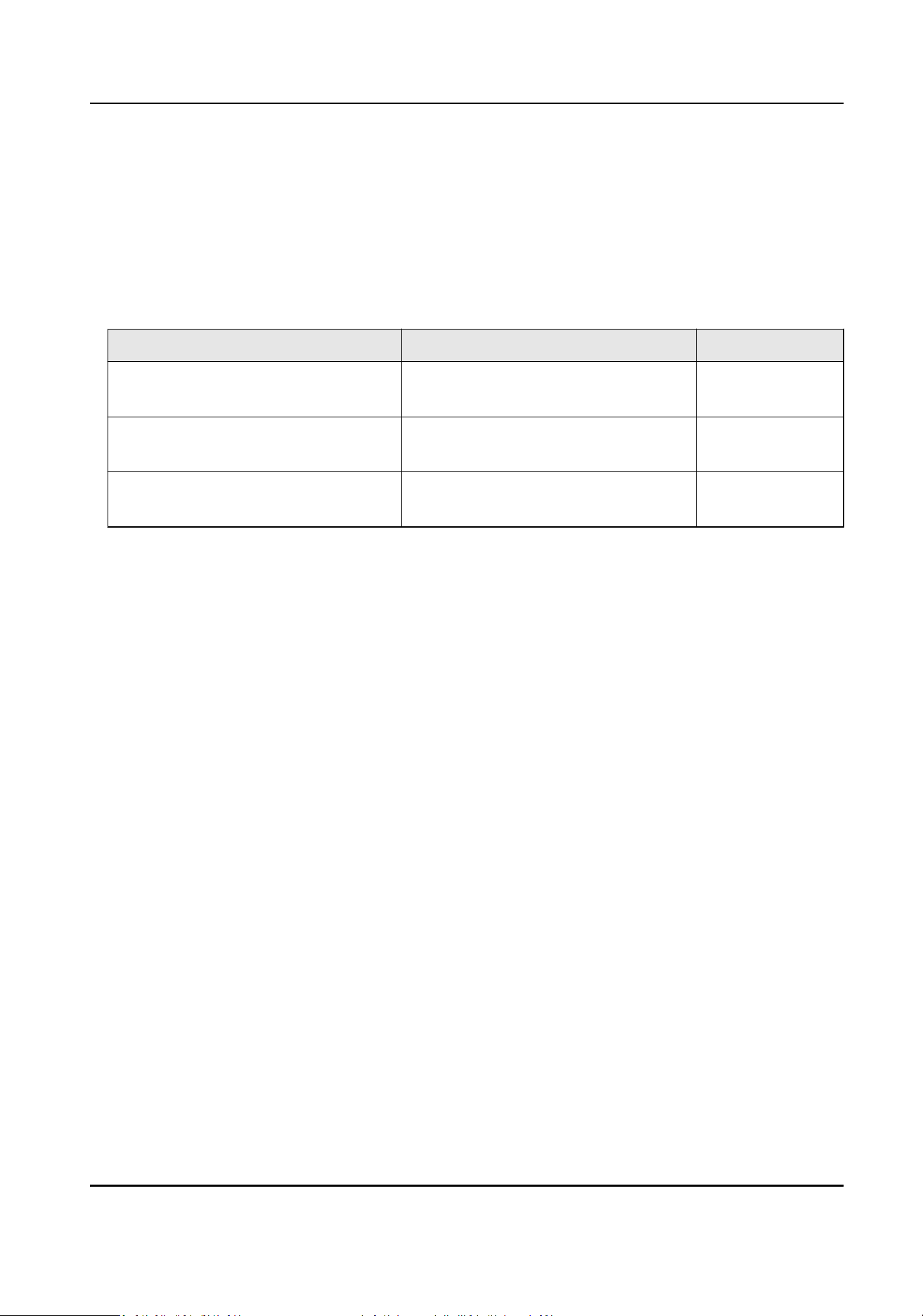
The power supply must conform to LPS. The recommended adaptor models and manufacturers
are shown as below. Use the aached adapter, and do not change the adaptor randomly.
Model Manufacturer Standard
ADS-24S-12 1224GPCN SHENZHEN HONOR ELECTRONIC
CO.,LTD
CEE
G0549-240-050 SHENZHEN GOSPELL DIGITAL
TECHNOLOGY CO.,LTD
CEE
TS-A018-120015Ec SHENZHEN TRANSIN TECHNOLOGIES
CO., LTD
CEE
Video Intercom Kit User Manual
v
Regulatory Informaon
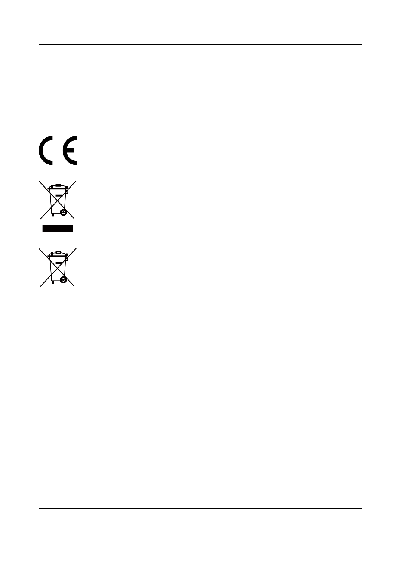
EU Conformity Statement
This product and - if applicable - the supplied accessories too are marked with "CE"
and comply therefore with the applicable harmonized European standards listed
under the EMC Direcve 2014/30/EU, RE Direcve 2014/53/EU,the RoHS Direcve
2011/65/EU
2012/19/EU (WEEE direcve): Products marked with this symbol cannot be disposed
of as unsorted municipal waste in the European Union. For proper recycling, return
this product to your local supplier upon the purchase of equivalent new equipment,
or dispose of it at designated collecon points. For more informaon see:
www.recyclethis.info
2006/66/EC (baery direcve): This product contains a baery that cannot be
disposed of as unsorted municipal waste in the European Union. See the product
documentaon for specic baery informaon. The baery is marked with this
symbol, which may include leering to indicate cadmium (Cd), lead (Pb), or mercury
(Hg). For proper recycling, return the baery to your supplier or to a designated
collecon point. For more informaon see:www.recyclethis.info
Industry Canada ICES-003 Compliance
This device meets the CAN ICES-3 (B)/NMB-3(B) standards requirements.
This device complies with Industry Canada licence-exempt RSS standard(s). Operaon is subject to
the following two condions:
1. this device may not cause interference, and
2. this device must accept any interference, including interference that may cause undesired
operaon of the device.
Le présent appareil est conforme aux CNR d'Industrie Canada applicables aux appareils
radioexempts de licence. L'exploitaon est autorisée aux deux condions suivantes :
1. l'appareil ne doit pas produire de brouillage, et
2. l'ulisateur de l'appareil doit accepter tout brouillage radioélectrique subi, même si le brouillage
est suscepble d'en compromere le fonconnement.
Under Industry Canada regulaons, this radio transmier may only operate using an antenna of a
type and maximum (or lesser) gain approved for the transmier by Industry Canada. To reduce
potenal radio interference to other users, the antenna type and its gain should be so chosen that
the equivalent isotropically radiated power (e.i.r.p.) is not more than that necessary for successful
communicaon.
Video Intercom Kit User Manual
vi

Conformément à la réglementaon d'Industrie Canada, le présent émeeur radio peut fonconner
avec une antenne d'un type et d'un gain maximal (ou inférieur) approuvé pour l'émeeur par
Industrie Canada. Dans le but de réduire les risques de brouillage radioélectrique à l'intenon des
autres ulisateurs, il faut choisir le type d'antenne et son gain de sorte que la puissance isotrope
rayonnée équivalente (p.i.r.e.) ne dépasse pas l'intensité nécessaire à l'établissement d'une
communicaon sasfaisante.
This equipment should be installed and operated with a minimum distance 20cm between the
radiator and your body.
Cet équipement doit être installé et ulisé à une distance minimale de 20 cm entre le radiateur et
votre corps.
Video Intercom Kit User Manual
vii

Contents
Chapter 1 About this Manual ...................................................................................................... 1
Chapter 2 Introducon ............................................................................................................... 2
Chapter 3 Appearance ................................................................................................................ 3
Chapter 4 Terminal and Wiring Descripon ................................................................................. 5
4.1 Terminal Descripon .............................................................................................................. 5
4.2 Wiring Descripon ................................................................................................................. 9
Chapter 5 Installaon ............................................................................................................... 11
5.1 Install Indoor Staon ............................................................................................................ 11
5.1.1 Wall Mounng with Juncon Box ............................................................................... 11
5.1.2 Mounng Indoor Staon without Juncon Box .......................................................... 12
5.2 Install Doorbell ..................................................................................................................... 13
Chapter 6 Acvaon ................................................................................................................. 16
6.1 Acvate Indoor Staon ........................................................................................................ 16
Chapter 7 Conguraon ........................................................................................................... 17
7.1 Local Operaon .................................................................................................................... 17
7.1.1 Quick Operaon .......................................................................................................... 17
7.1.2 Basic Sengs .............................................................................................................. 23
7.1.3 Password Sengs ....................................................................................................... 34
7.1.4 Synchronize Time ........................................................................................................ 36
7.1.5 Sound Sengs ............................................................................................................ 37
7.1.6 Link to the Mobile Client ............................................................................................. 40
7.1.7 System Sengs ........................................................................................................... 41
7.1.8 Output Sengs ........................................................................................................... 44
7.1.9 Device Informaon ..................................................................................................... 45
Chapter 8 Operaon ................................................................................................................. 46
8.1 Local Operaon .................................................................................................................... 46
Video Intercom Kit User Manual
viii

8.1.1 Call Sengs ................................................................................................................. 46
8.1.2 Leave Message ............................................................................................................ 49
8.1.3 Live View ..................................................................................................................... 49
8.1.4 Arm/Disarm ................................................................................................................ 51
8.1.5 Call Elevator ................................................................................................................ 53
8.1.6 Relay Sengs .............................................................................................................. 54
8.1.7 Informaon Management ........................................................................................... 54
Appendix A. Cables ................................................................................................................... 56
Video Intercom Kit User Manual
ix

Chapter 1 About this Manual
Get the manual and related soware from or the ocial website (hp://www.hikvision.com).
Product Model
Network Indoor Staon DS-KH6320-WTDE1
Doorphone DS-KB2421T-IM
Video Intercom Kit User Manual
1

Chapter 2 Introducon
Features of the hybrid video intercom products:
●
User-friendly control with a convenient touch screen.
●
Convenient management via the Hik-Connect mobile client.
●
More cost-eecve opons with analog doorbells.
●
Easy installaon as the doorbell requires no exclusive power supply.
Video Intercom Kit User Manual
2
Chapter 3 Appearance
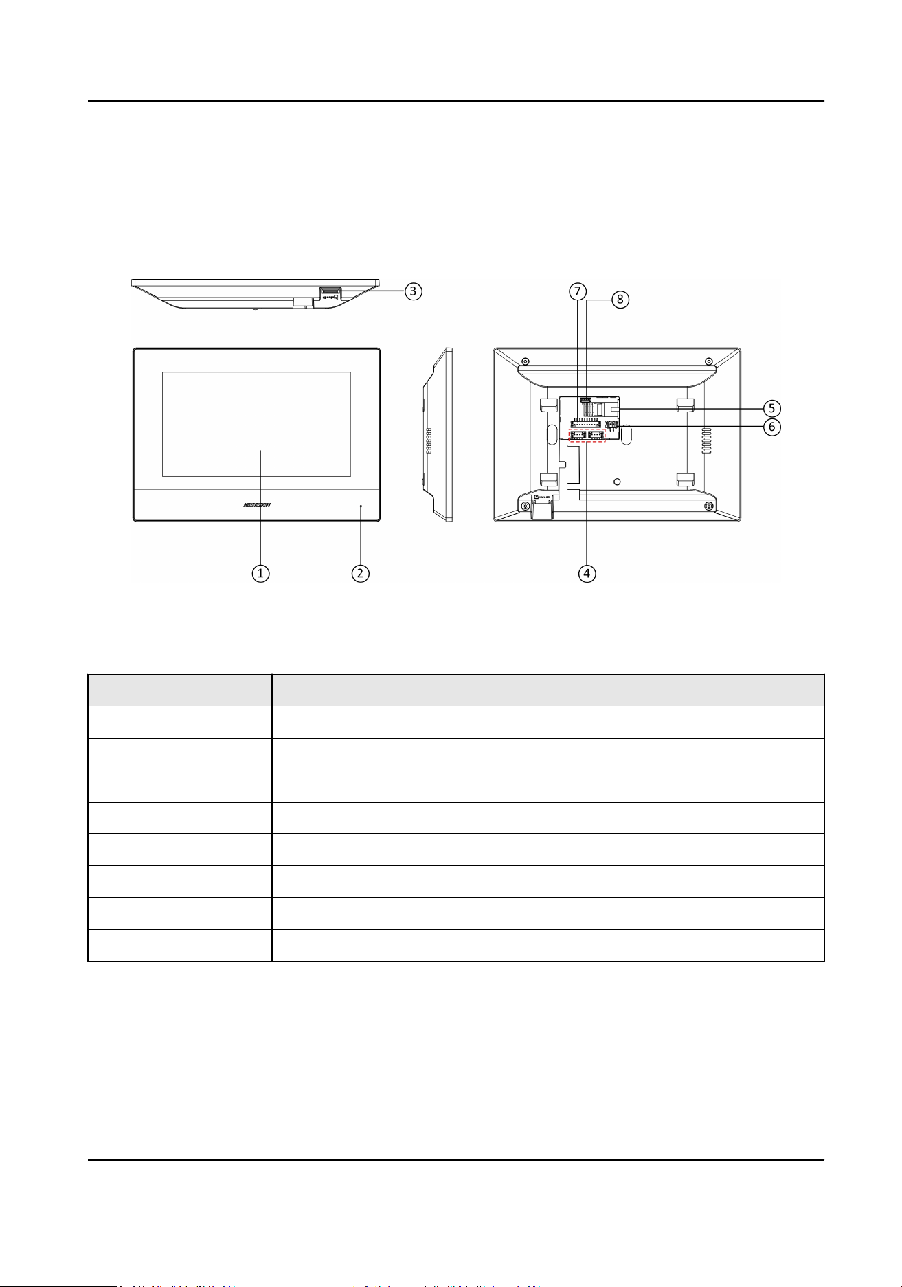
Network Indoor Staon
Figure 3-1 Appearance of Indoor Staon
Table 3-1 Descripon
No. Descripon
1 Screen
2 Microphone
3 SD Card Slot
4 Four-Wire Terminals
5 Network Interface
6 Power Supply Interface
7 Alarm Input/Relay Output/RS-485 Interface
8 Serial Port (For Debugging Use Only)
Video Intercom Kit User Manual
3
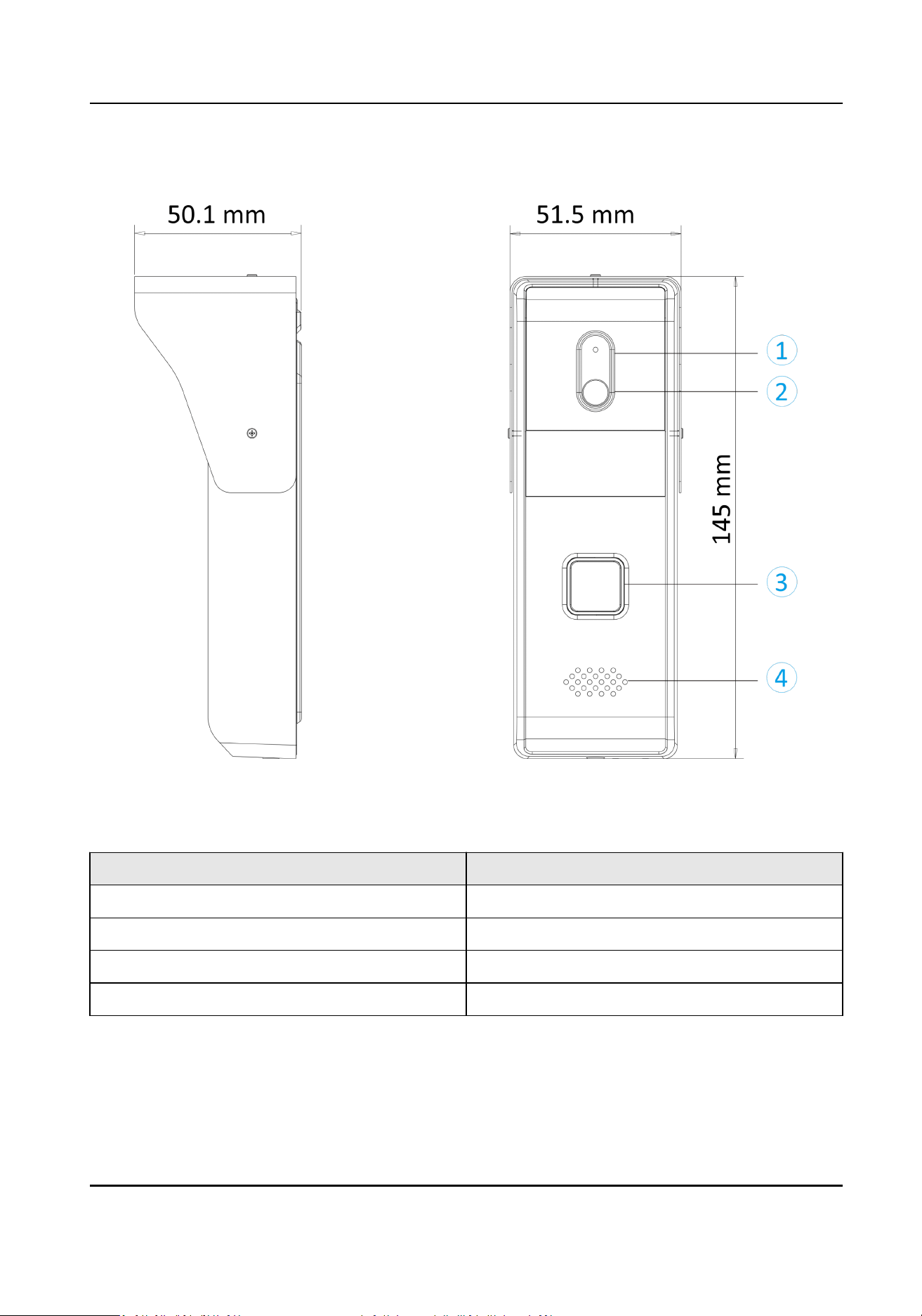
Doorphone
Figure 3-2 Appearance of Doorphone
Table 3-2 Descripon
No. Descripon
1 Microphone
2 Built-in Camera
3 Call Buon
4 Loud Speaker
Video Intercom Kit User Manual
4
Chapter 4 Terminal and Wiring Descripon
4.1 Terminal Descripon
Note
You can refer to Appendix for more details about cable specicaon.
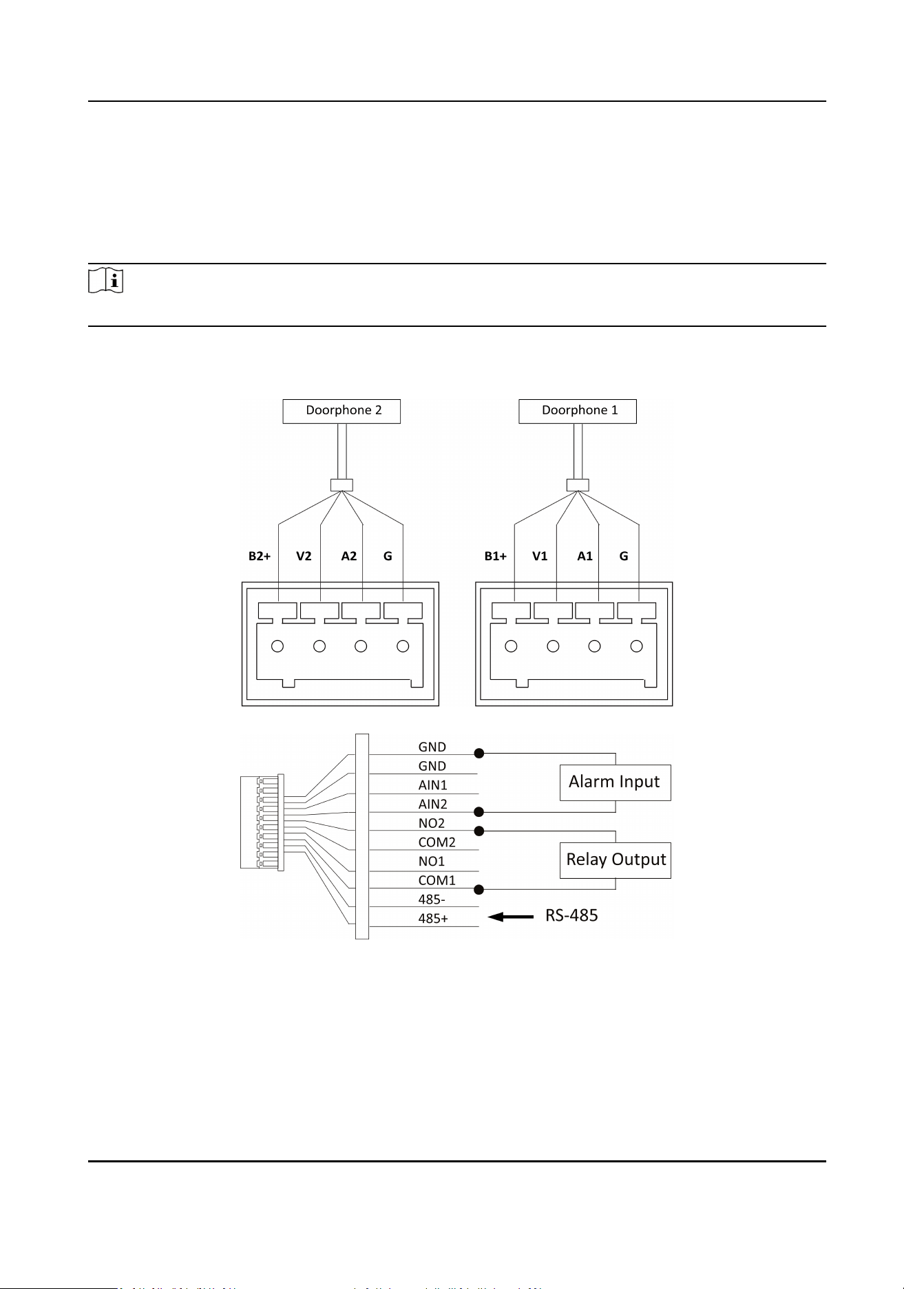
Network Indoor Staon Wiring
Figure 4-1 Terminal of Indoor Staon
Video Intercom Kit User Manual
5
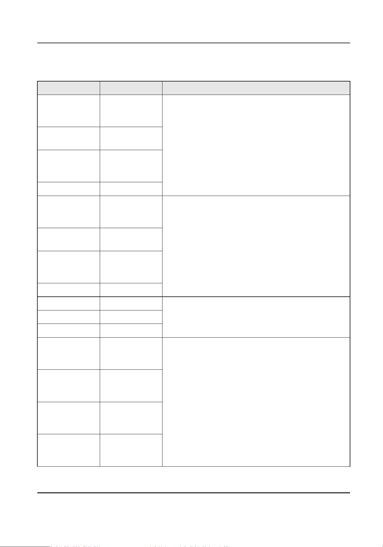
Table 4-1 Descripons of Terminal and Interfaces
Interface Descripon Funcon
B1+ 12 VDC Power
supply for
doorphone 1
For the connecon of doorphone 1
V1 Video input of
doorphone 1
A1 Audio input/
output of
doorphone 1
G Grounding
B2+ 12 VDC Power
supply for
doorphone 2
For the connecon of doorphone 2
V2 Video input of
doorphone 2
A2 Audio input/
output of
doorphone 2
G Grounding
GND Grounding For the connecon of alarm input devices
AIN1 Alarm input 1
AIN2 Alarm input 2
COM1 Door lock relay
output 1
(common)
For the connecon of door locks
NO1 Door lock relay
output 1
(normally open)
COM2 Door lock relay
output 2
(common)
NO2 Door lock relay
output 2
(normally open)
Video Intercom Kit User Manual
6
Interface Descripon Funcon
485+ RS-485+ Interface For the connecon of devices via RS-485
485- RS-485- Interface
Video Intercom Kit User Manual
7
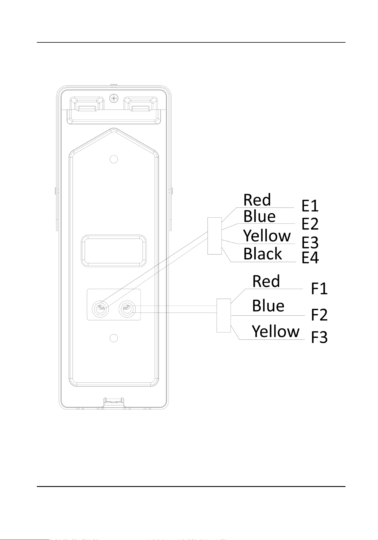
Doorphone Wiring
Figure 4-2 Terminal of Doorphone
Video Intercom Kit User Manual
8
Table 4-2 Descripons of Terminal and Interfaces
Interface Descripon Funcon
E1 5V: Power Supply
(from Indoor
Staon)
For the connecon of indoor staon
E2 CVBS: Video
Output
E3 AUDIO: Audio
Input/Output
E4 GND: Grounding
Signal
F1 NO: Door Lock
Relay Output/
Normally Open
For the connecon of door lock
F2 COM: Door Lock
Relay Output/
Common
F3 NC: Door Lock
Relay Output/
Normally Closed
4.2 Wiring Descripon
The Typical applicaon is shown as below.
Cauon
Make sure all the related equipment is power-o during the wiring and installaon.
Video Intercom Kit User Manual
9
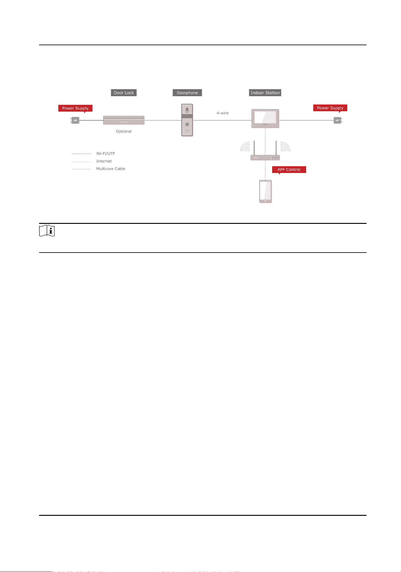
Typical Applicaon
Figure 4-3 Topology
Note
●
Network indoor staon can be connected to LAN(PoE) with Network Cable.
Video Intercom Kit User Manual
10
Chapter 5 Installaon
5.1 Install Indoor Staon
5.1.1 Wall Mounng with Juncon Box
Before You Start
Note
●
Make sure the device in the package is in good condion and all the assembly parts are included.
●
The power supply the indoor staon supports is 12 VDC. Please make sure your power supply
matches your indoor staon.
●
Make sure all the related equipment is power-o during the installaon.
●
Check the product specicaon for the installaon environment.
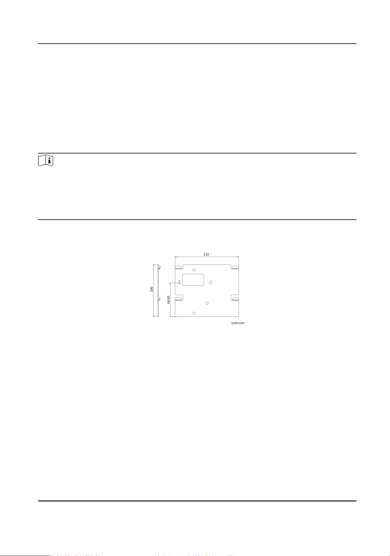
The dimension of juncon box should be 75 mm (width) × 75 mm (length) × 50 mm (depth). The
dimension of wall mounng plate is shown.
Figure 5-1 Wall Mounng Plate
Steps
1.
Chisel a hole in the wall. The size of the hole should be 76 mm (width) × 76 mm (length) × 50
mm (depth).
2.
Insert the juncon box to the hole chiseled on the wall.
3.
Fix the wall mounng plate to the juncon box with 2 screws.
4.
Hook the indoor staon to the wall mounng plate ghtly by inserng the plate hooks into the
slots on the rear panel of the indoor staon, during which the lock catch will be locked
automacally.
Video Intercom Kit User Manual
11
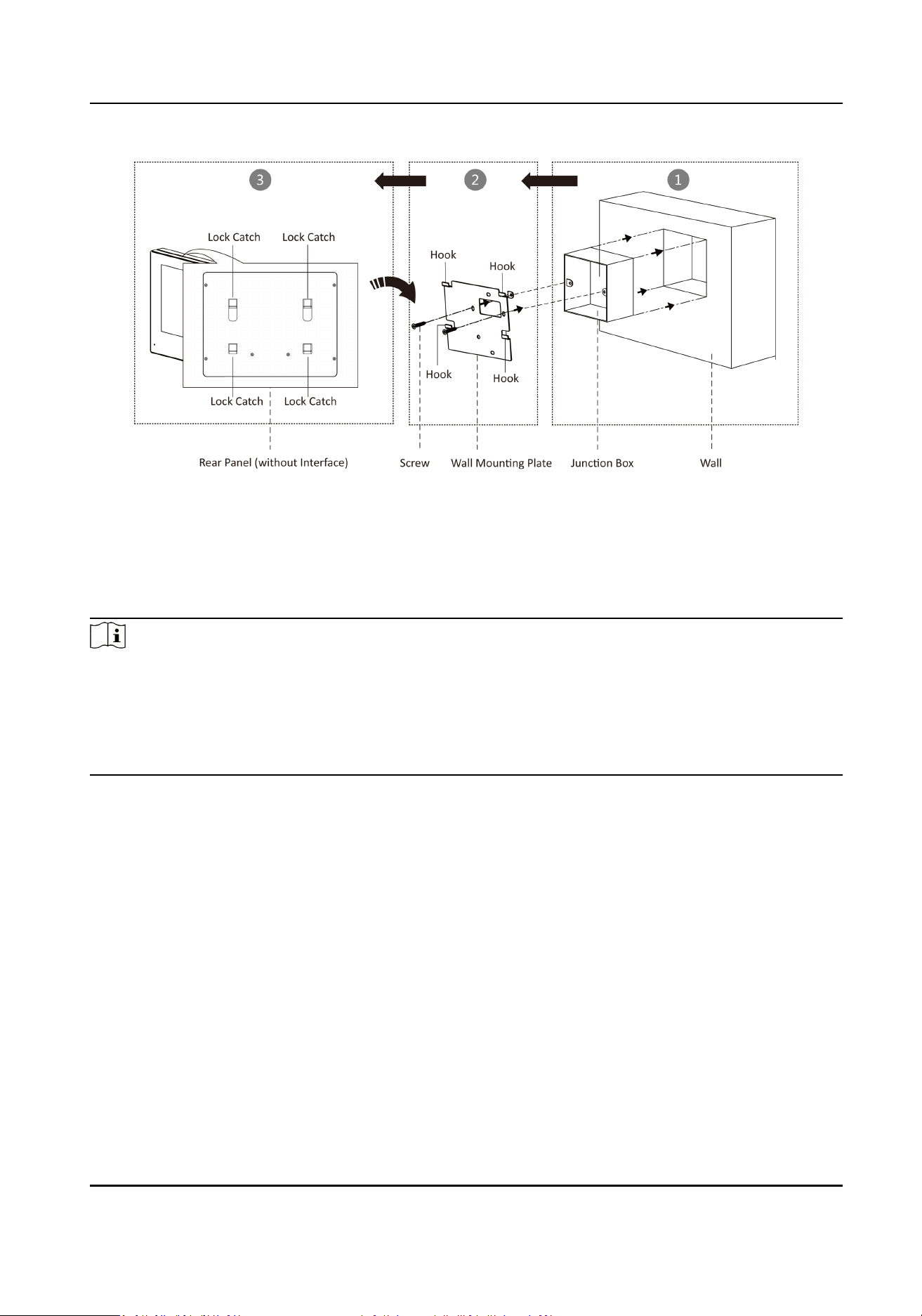
Figure 5-2 Wall Mounng with Juncon Box
5.1.2 Mounng Indoor Staon without Juncon Box
Before You Start
Note
●
Make sure the device in the package is in good condion and all the assembly parts are included.
●
The power supply the indoor staon supports is 12 VDC. Please make sure your power supply
matches your indoor staon.
●
Make sure all the related equipment is power-o during the installaon.
●
Check the product specicaon for the installaon environment.
Steps
1.
Insert 2 expension tubes into the wall.
2.
Fix the wall mounng plate to the juncon box with 2 screws.
3.
Hook the indoor staon to the wall mounng plate ghtly by inserng the plate hooks into the
slots on the rear panel of the indoor staon, during which the lock catch will be locked
automacally.
Video Intercom Kit User Manual
12
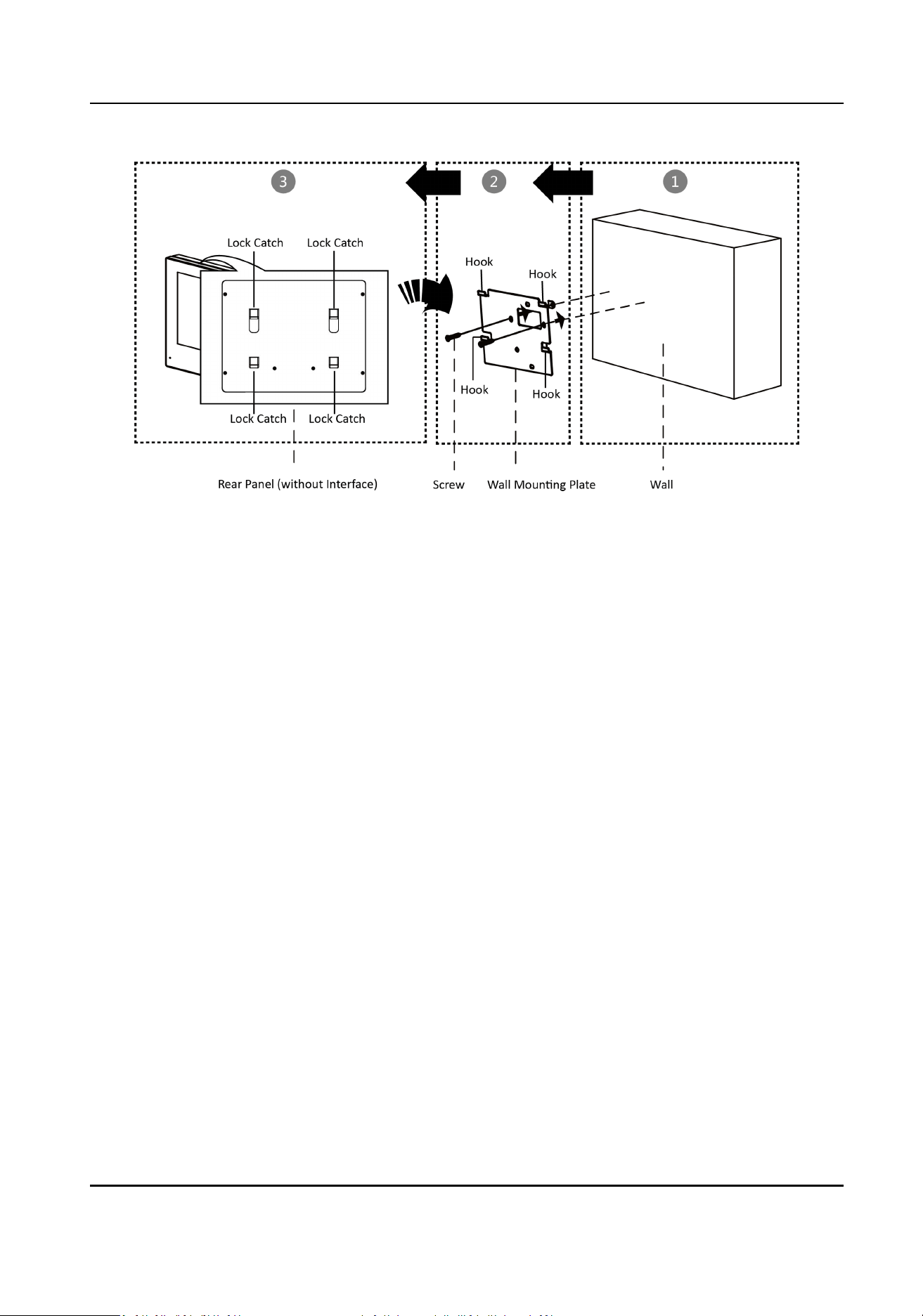
Figure 5-3 Wall Mounng without Juncon Box
5.2 Install Doorbell
Before You Start
●
Make sure you have powered o the main power switch of your home.
●
Make sure you have connected power cables of the doorbell.
The Dimension of the wall mounng plate is shown below.
Video Intercom Kit User Manual
13
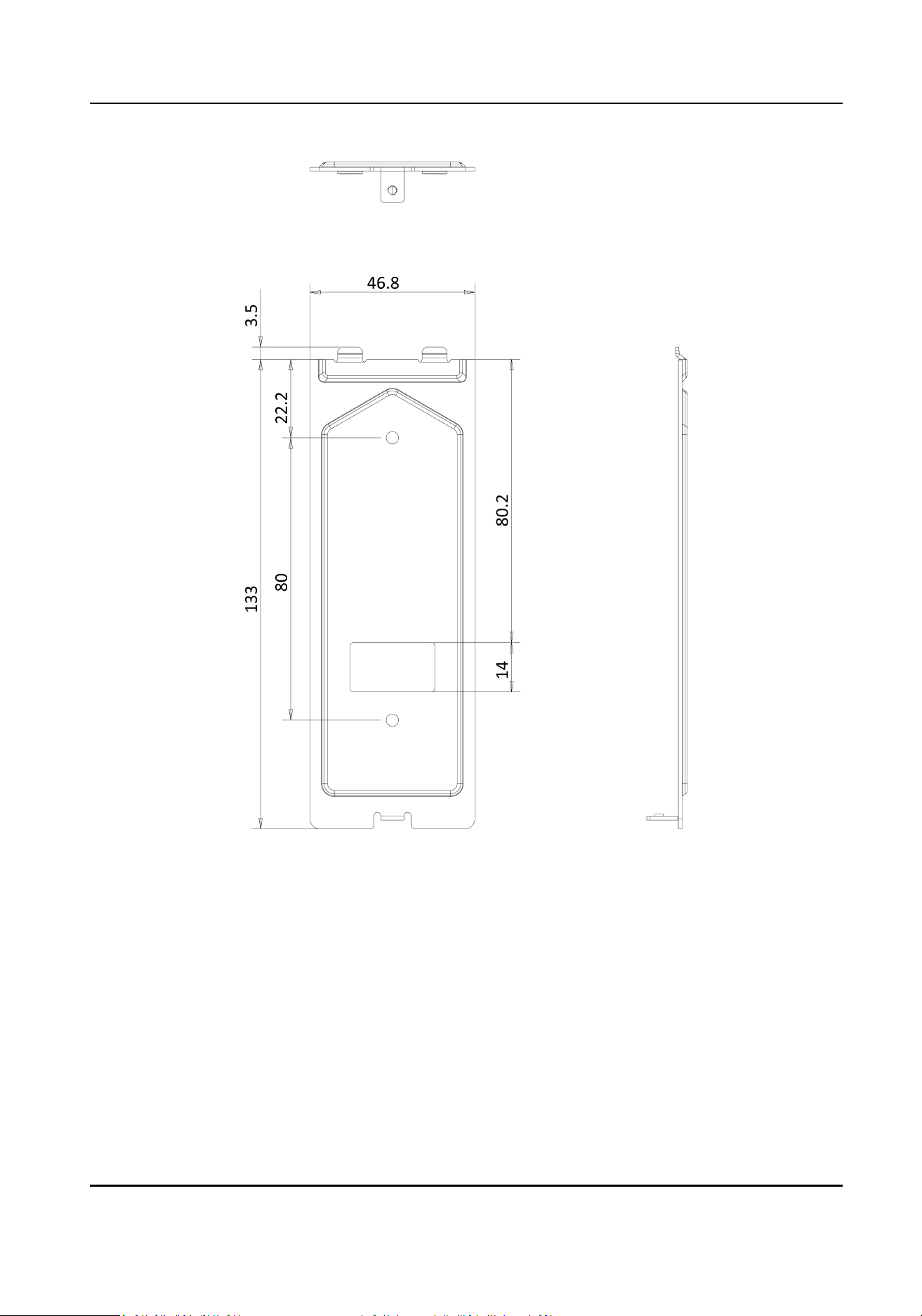
Figure 5-4 Wall Mounng Plate
Steps
1.
Fix the wall mounng shield to the wall with 2 screws.
2.
Hook the door staon to the shield ghtly by inserng the hooks of shield panel into the slots on
the rear panel of the door staon.
3.
Secure the door staon with the mounng shield with the set screw.
Video Intercom Kit User Manual
14
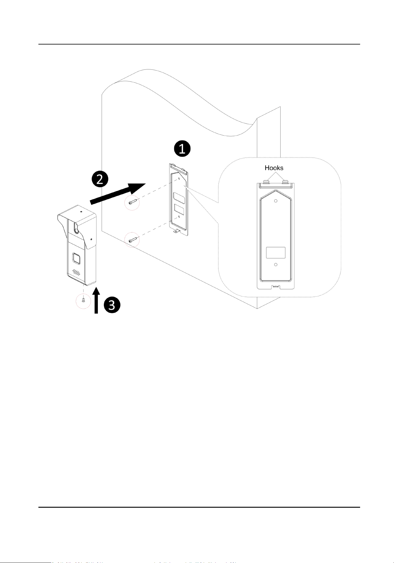
Figure 5-5 Wall Mounng
Video Intercom Kit User Manual
15
Chapter 6 Acvaon
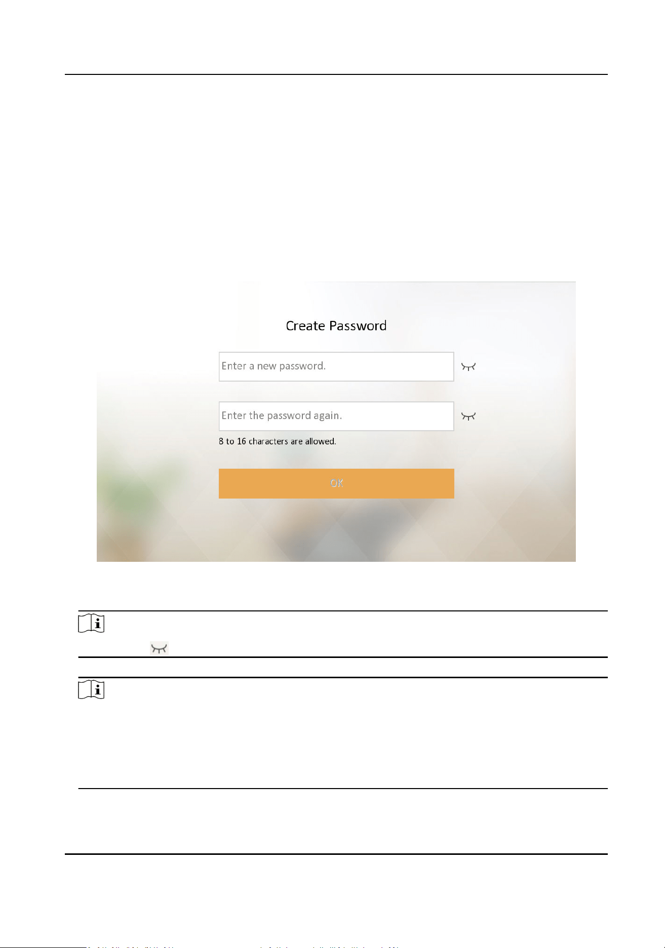
6.1 Acvate Indoor Staon
You can congure and operate the indoor staon aer creang a password for the device
acvaon.
Steps
1.
Power on the device. It will enter the acvaon page.
Figure 6-1 Acvaon Page
2.
Create a password and conrm it.
Note
You can click to enable or disable password reveal.
3.
Tap OK to acvate the indoor staon.
Note
We highly recommend you to create a strong password of your own choosing (using a minimum
of 8 characters, including at least three kinds of following categories: upper case leers, lower
case leers, numbers, and special characters) in order to increase the security of your product.
And we recommend you change your password regularly, especially in the high security system,
changing the password monthly or weekly can beer protect your product.
Aer device acvaon, the wizard page will pop up.
Video Intercom Kit User Manual
16
Chapter 7 Conguraon
7.1 Local Operaon
7.1.1 Quick Operaon
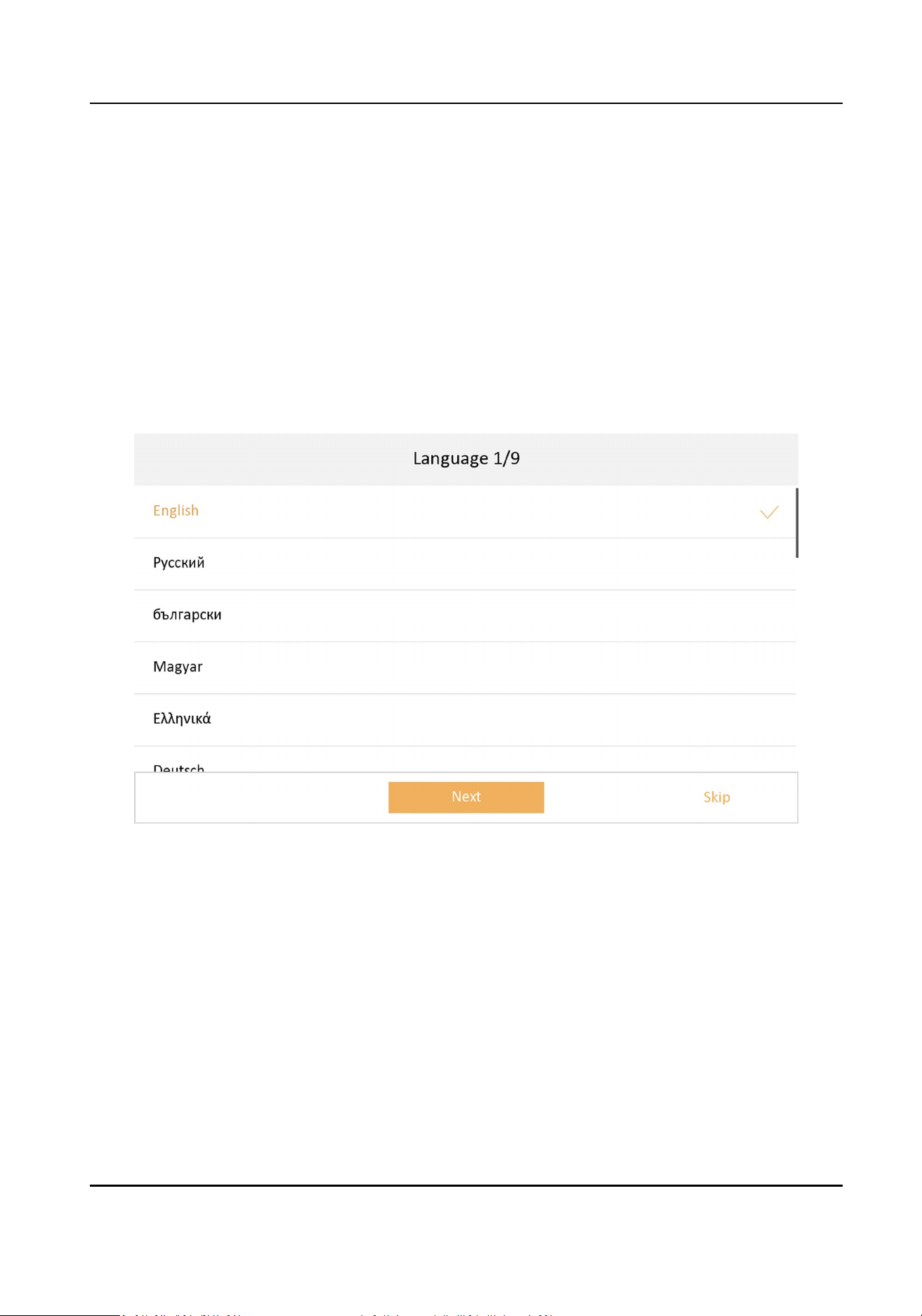
Aer device acvaon, the wizard page will pop up. The descripon is for other indoor staons.
Steps
1.
Choose language and tap Next.
Figure 7-1 Language Sengs
2.
Set password reset methods and tap Next.
-
Bind an email address. If you forget your admin and acvaon password, you can change the
password via the reserved email address.
-
Tap Change to Security Queson to select security quesons and enter the answers. If you
forget your admin and acvaon password, you can change the password via answering the
quesons.
Video Intercom Kit User Manual
17
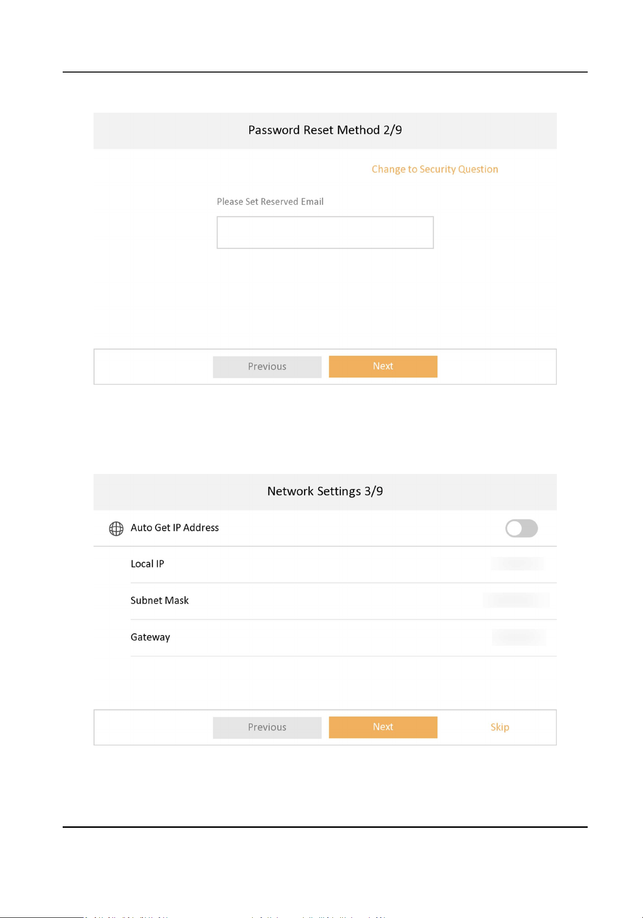
Figure 7-2 Password Reset Methods
3.
Set network parameters and tap Next.
-
Edit Local IP, Subnet Mask and Gateway parameters manually.
-
Enable Auto Get IP address, the device will get network parameters automacally.
Figure 7-3 Network Parameters
Video Intercom Kit User Manual
18
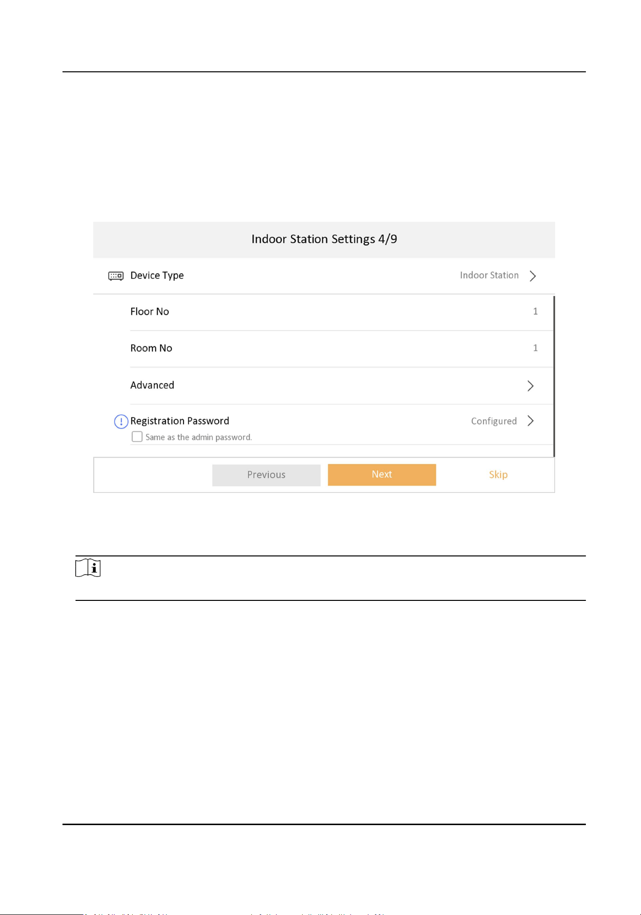
4.
Congure the indoor staon.
1) Select Device Type as Indoor Staon or Indoor Extension.
2) Set Floor No..
3) Set Room No..
4) Congure advanced sengs. Set Comminity No., Building No. and Unit No.
5) Set Registraon Password.
6) Tap Next.
Figure 7-4 Indoor Staon Sengs
5.
Enable the Wi-Fi funcon. Select a Wi-Fi from the list and enter the Wi-Fi's password to get
connected. Tap Next.
Note
The device should support Wi-Fi.
Video Intercom Kit User Manual
19
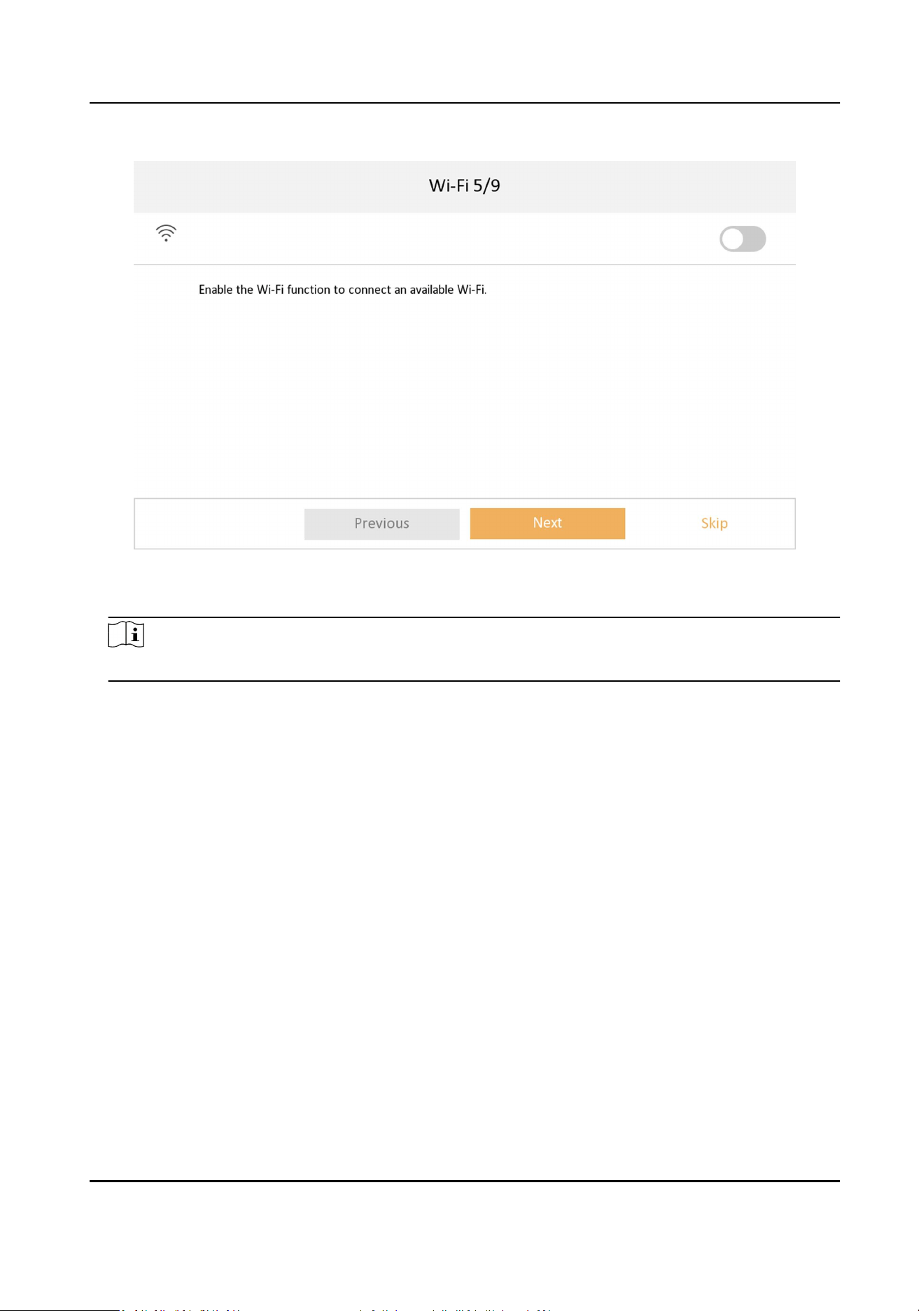
Figure 7-5 Wi-Fi
6.
Set me and tap Next.
Note
The me can be synchronized to door staons.
1) Select the Time Zone.
2) Tap Date Format and Time Format to set the me format.
3) Tap Time to set me manually.
4) Enable DST.Set the DST start me, end me and bias me.
Video Intercom Kit User Manual
20
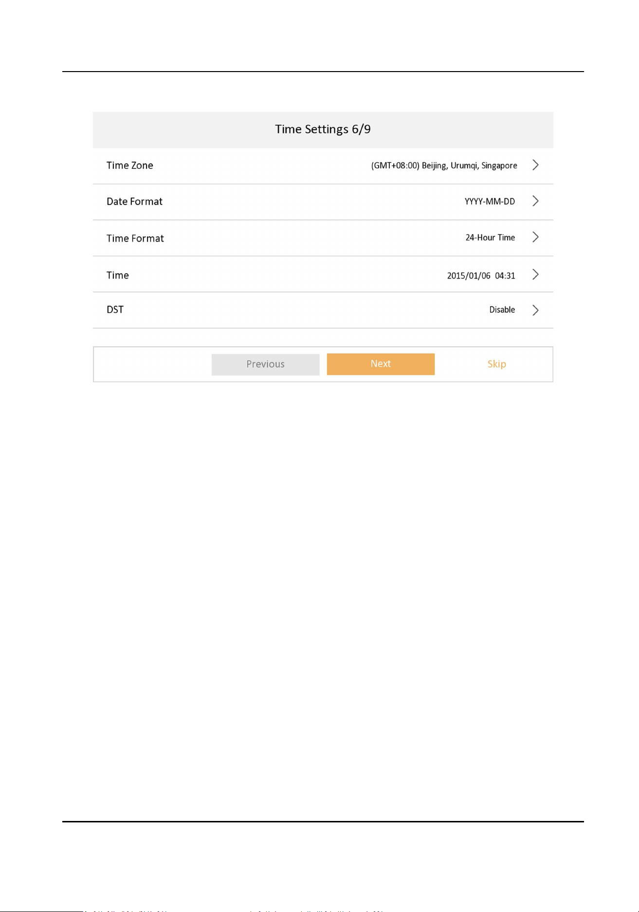
Figure 7-6 Time Sengs
7.
Congure the Hik-Connect service sengs.
1) Enable Hik-Connect service.
2) Edit vericaon code or use the acvaon password by default.
3) View Hik-Connect Server Status.
4) Scan the rst QR Code to download the APP of Hik-Connect. Scan the second QR Code to add
your device to the APP. Aer adding the device to the APP, you can congure the device
remotely.
5) Tap Next.
Video Intercom Kit User Manual
21
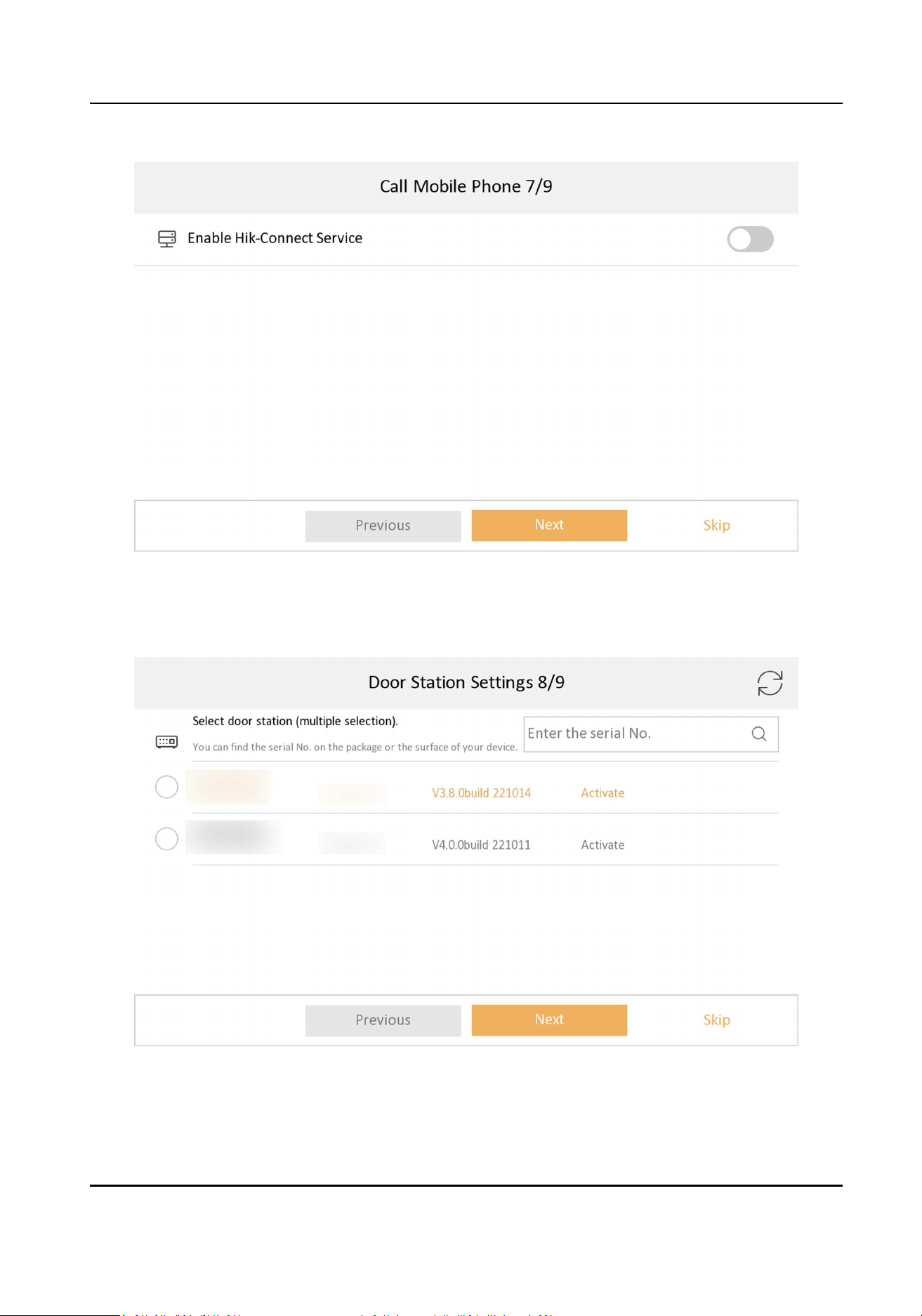
Figure 7-7 Hik-Connect Service Sengs
8.
Link related devices and tap Next. If the device and the indoor staon are in the same LAN, the
device will be displayed in the list.
Figure 7-8 Related Device
1) Tap the door staon in the list to link.
Video Intercom Kit User Manual
22
Note
If the door staon is inacve, the system will pop up the dialog to acvate the door staon.
2) Edit the network parameters of the door staon manually.
3) Tap Next.
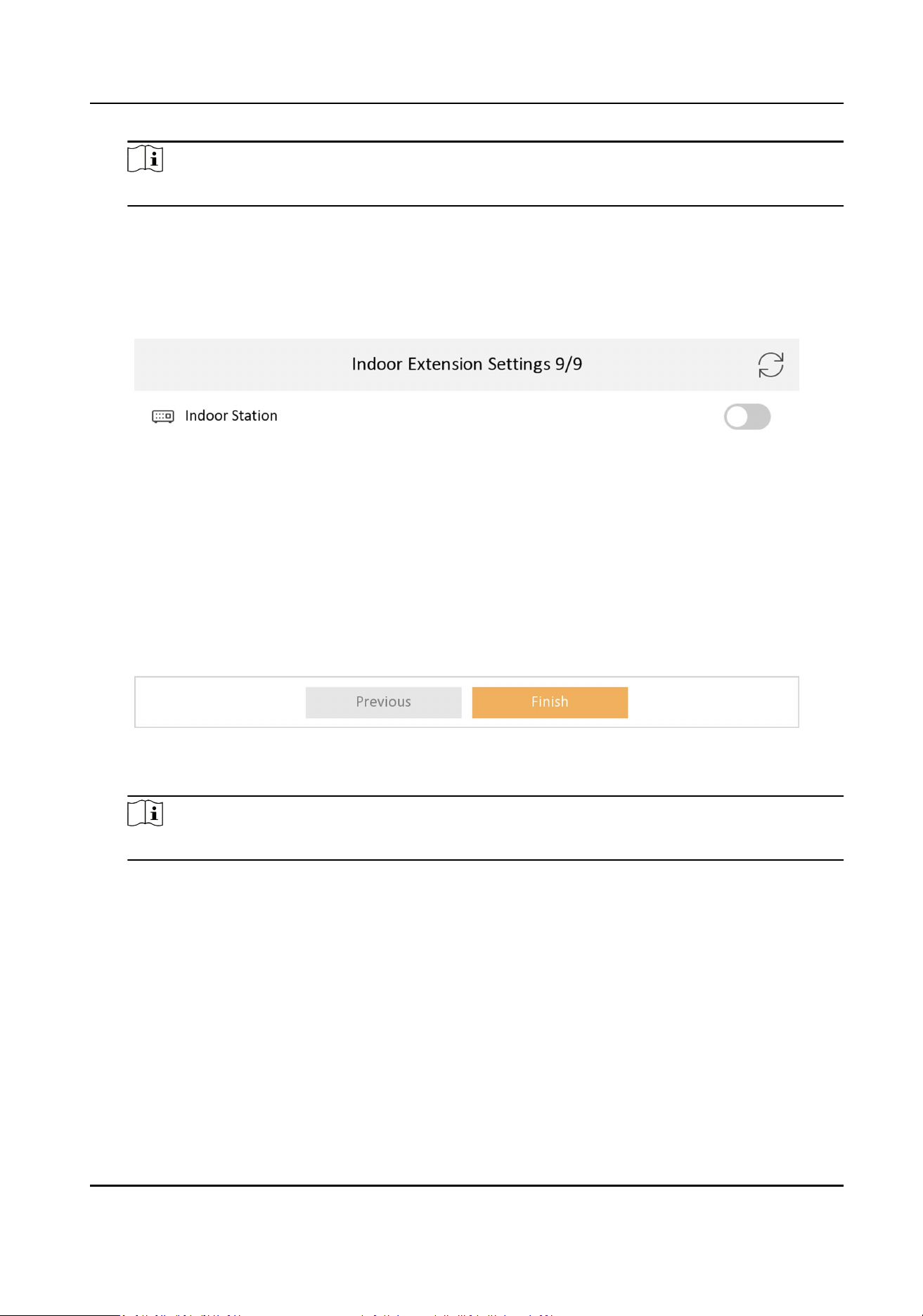
9.
Oponal: Enable Indoor Staon and link related indoor extension devices. Tap Finish. If the
indoor extension and the indoor staon are in the same LAN, the device will be displayed in the
list. Tap the device or enter the serial No. to link.
Figure 7-9 Related Device
1) Tap the indoor extension in the list to link.
Note
If the indoor extension is inacve, the system will pop up the dialog to acvate the device.
10.
Tap Finish to save the sengs.
7.1.2 Basic Sengs
Basic sengs is required before starng using the indoor staon. It is necessary to set the indoor
staon network, room No., linked devices, device me display, and so on.
Video Intercom Kit User Manual
23
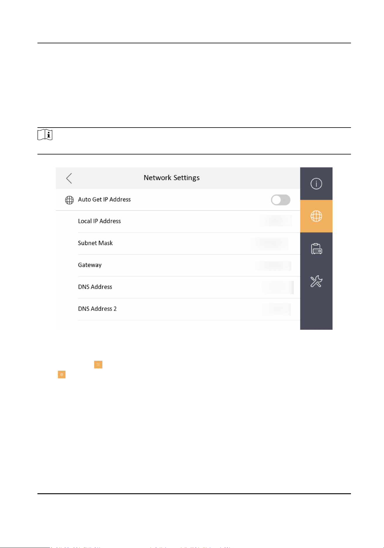
Set Indoor Staon Network Parameters
Network connecon is mandatory for the use of the indoor staon. Set the network parameters
aer acvang the indoor staon. Only when the IP address of the indoor staon is in the same
network segment as other devices, it can work properly in the same system.
Steps
Note
The default IP address of the indoor staon is 192.0.0.64.
Figure 7-10 Network Informaon
Two ways are available for you to set IP address: DHCP, and set IP address manually.
1.
Tap Sengs →
→ Conguraon , and enter admin (acvaon) password.
2.
Tap to enter the network sengs page.
3.
Set the network parameters.
-
Enable DHCP, and the system can assign an IP address of the indoor staon automacally.
-
Disable the DHCP funcon, and set the IP address manually. You should set the device IP
address, the gateway, the DNS address.
Connect to Wi-Fi
Set Wi-Fi connecon.
Video Intercom Kit User Manual
24
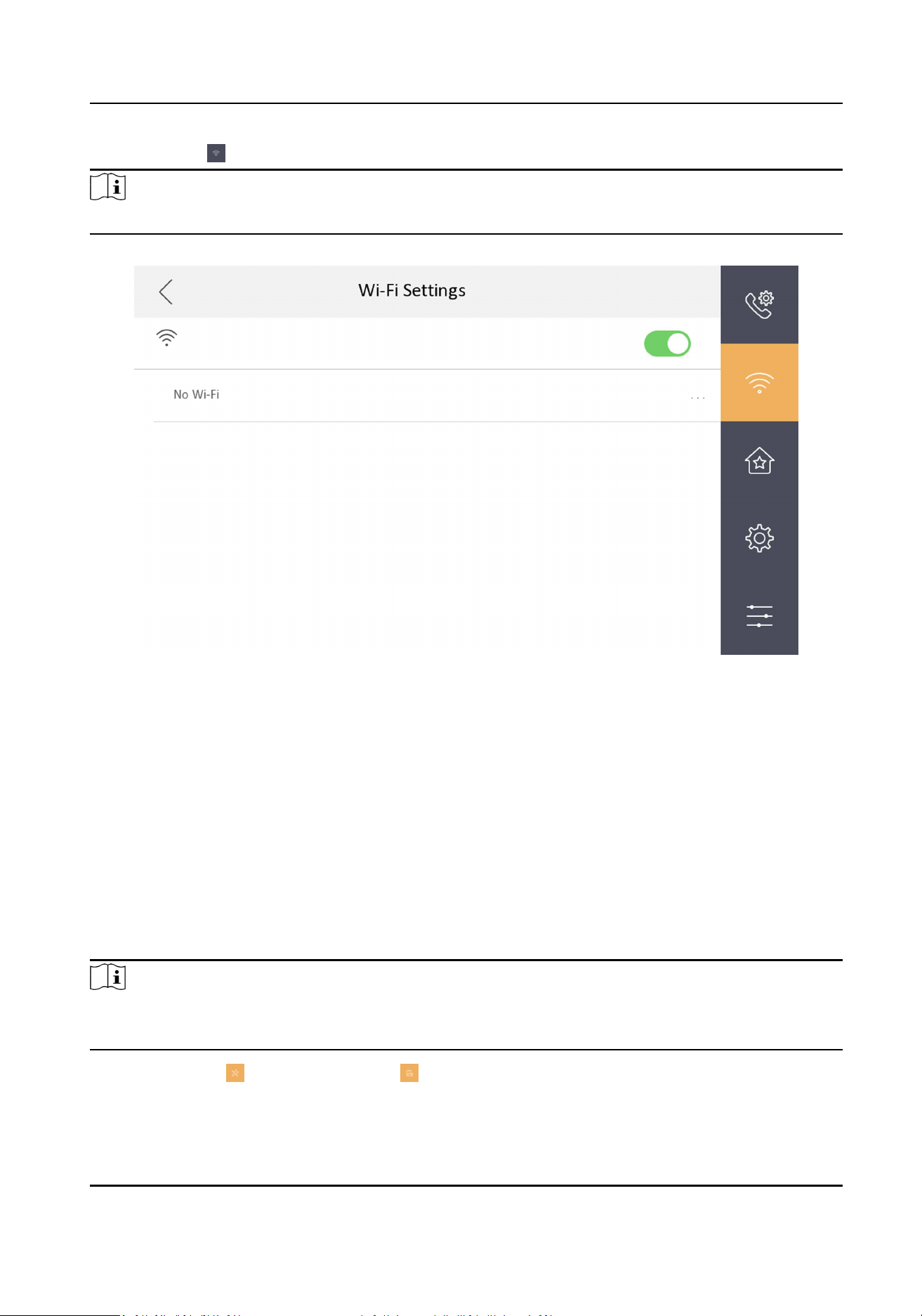
Tap Sengs → . Enable Wi-Fi, and the indoor staon will search available Wi-Fi automacally.
Note
The Wi-Fi IP can be changed.
Figure 7-11 Wi-Fi Sengs
Select an Wi-Fi and connect.
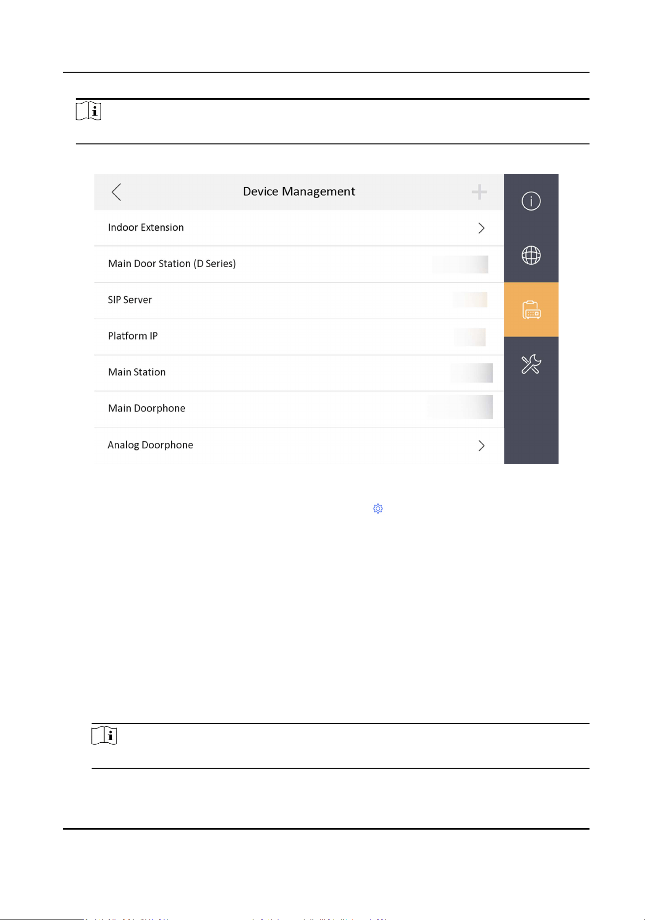
Set Linked Device IP
Linked network parameters refers to the network parameters of devices (like door staon,
doorphone, main staon, center, etc.), to which the indoor staon is linked. Linked devices for the
indoor staon refers to door staon, center, main staon, and doorphone.
With the private SIP protocol, intercom can be realized only when all these devices are in the same
network segment with the indoor staon.
Steps
Note
●
The doorphone does not support adding with the standard SIP protocol.
●
Here take main door staon network sengs as example.
1.
Tap Sengs → → Conguraon → to enter the device management page.
Video Intercom Kit User Manual
25
Note
Default admin password is the acvaon password.
2.
Tap Main Door Staon to pop up the device informaon dialog.
Figure 7-13 Device Informaon
Set the parameters of the linked door staon. Tap
to set parameters of the door staon.
3.
Select a device to link. Edit the following parameters.
Name
You can edit the name of the device.
Language
Select a language from the drop-down list for the device.
Network
Enable Auto Get IP Address and the system will assign IP address, subnet mask, and gateway
automacally. Or edit the IP address, subnet mask, and gateway manually.
Door Lock Parameters
Aer wire the lock with the door staon, you can set name and door opening duraon
according to your needs.
Note
Up to 2 locks can be congured.
Video Intercom Kit User Manual
26
Volume Sengs
Set microphone volume and output volume.
Call Number Sengs
The call No. should be the same as the indoor staon's room No. If press the call buon of
the door staon, you can call the indoor staon directly.
Public Password
You can use the public password to open the door staon related door lock. Select the public
password type. Enter the old password and new password and then conrm the new
password. Tap OK to save the sengs.
Restore to Default Sengs
Restore All
All parameters will be restored to the factory sengs. The system will reboot to take
eect.
Device Reboot
Reboot the device.
Set Local Informaon
Indoor staon No. and the indoor extension No. are numbers, which can be dialed by other devices
to call the indoor staon and the indoor extension in an intercom system. The indoor staon No., is
composed of the oor No., room No., community No., building No. and unit No.
The indoor extension No. Should be a numeric from 1 to 5.
Up to 5 indoor extensions can be set for 1 indoor staon.
Steps
1.
Tap Sengs →
→ Conguraon → to enter the indoor staon No. sengs page.
Note
Default admin password is the acvaon password.
Video Intercom Kit User Manual
27
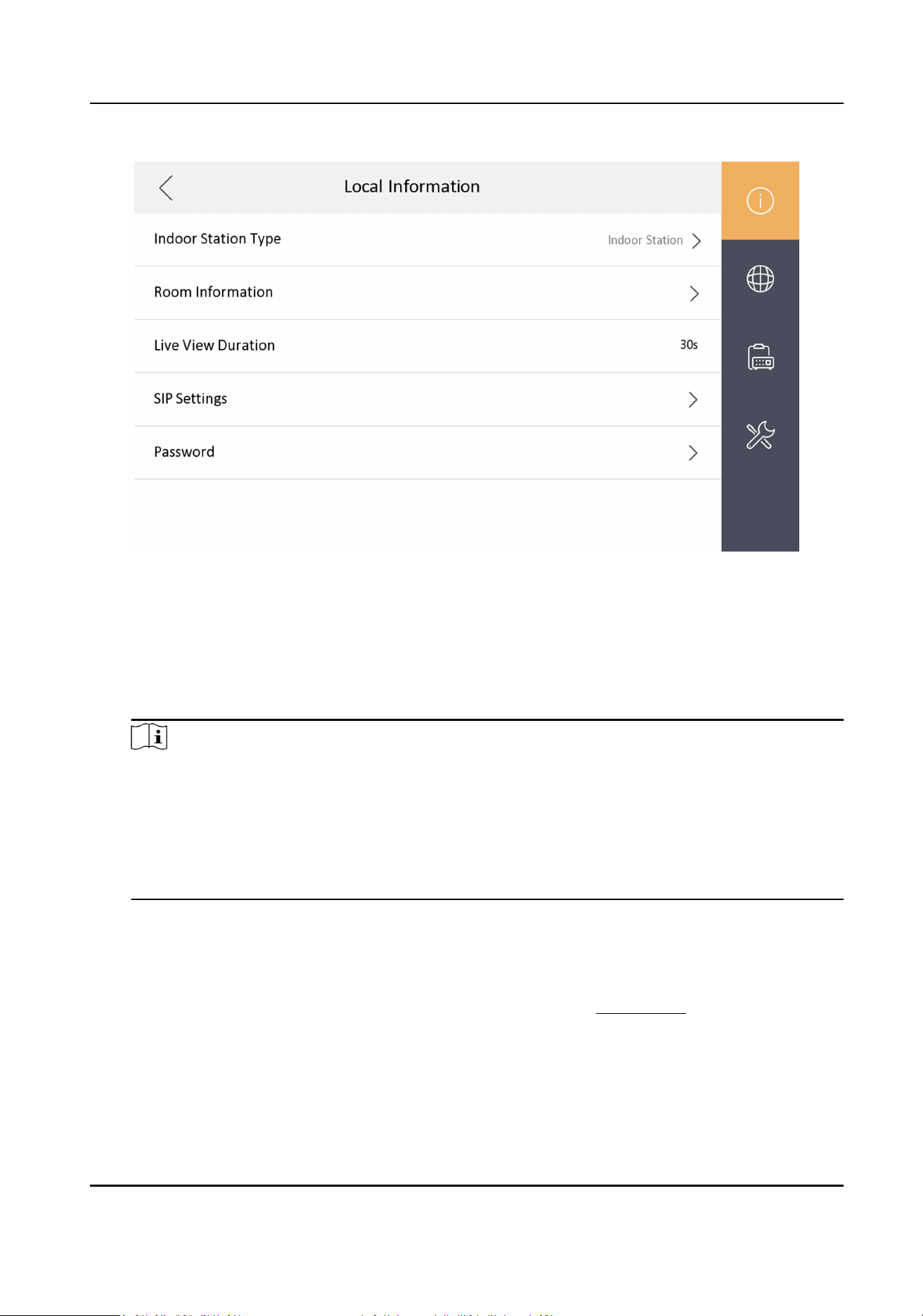
Figure 7-14 Set Indoor Staon No.
2.
Select Indoor Staon to set the room informaon, live view duraon, SIP parameters and
password.
Room Informaon
You can set room name, oor No., and room No. Tap Advanced Sengs to set community
No., building No. and unit No. if you need.
Note
●
Community No., building No., and unit No. can be omied if there is no such informaon.
●
If there are two indoor staons that are in the same building, and should call each other,
enter the the room No. directly to call.
●
If there are two indoor staons that are in two buildings, and should call each other, enter
the building No. and the room No. to call. For examle, call 1-405 to call room 405 in
building 1.
Live View Duraon
You can set the duraon of live view.
SIP Sengs
You can set SIP parameters. For more details, please refer to: SIP Sengs
Password Sengs
You can set unlock password and duress code.
3.
Select Indoor Extension to set the room informaon, live view duraon, registraon password
and enable SIP 1.0 according to your needs.
Video Intercom Kit User Manual
28

Room Informaon
You can set room name and No. Tap Advanced to set the community No., building No., and
unit No. if you need.
When calling the indoor staon and the two devices are in the same building, you can call the
room No. directly.
Live View Duraon
You can set the duraon of live view.
Registraon Password
You can create a new registraon password.
Enable SIP 1.0
You can enable SIP 1.0 protocol according to your needs.
Analog Doorphone Sengs
The analog doorphone and sub doorphone share the capacity quanty. You can add maximum 1
doorphone + 14 sub doorphone + 2 analog doorphone to one indoor staon. (If there is no analog
doorphone, you can add 1 doorphone + 16 sub doorphone to one indoor staon.)
Steps
1.
Tap Sengs → → Conguraon , and enter admin (acvaon) password.
2.
Tap to enter the device management page.
3.
Tap Analog Doorphone.
4.
Set the name and the unlock me. Click OK to save the sengs.
Video Intercom Kit User Manual
29
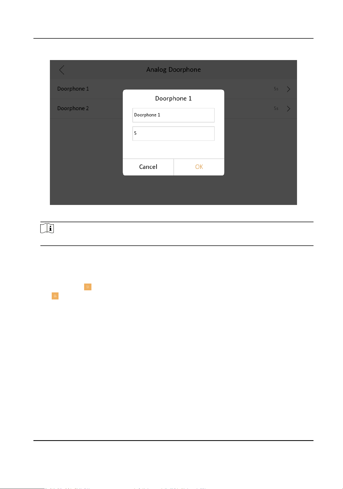
Figure 7-15 Analog Doorphone
Note
The unlock me is between 1 s to 255 s.
Add Camera
Steps
1.
Tap Sengs → → Conguraon , and enter admin (acvaon) password.
2.
Tap to enter the device management page.
3.
Tap + to pop up the dialog box.
4.
Select a protocol to add the camera.
-
Select HIK Protocol and you can add the camera depended on the HIK protocol.
Enter the device name, IP address, user name and the password of the camera. Edit port No.
and channel No.
Exit the page to save the sengs.
-
Select Open Network Video Interface to add the camera.
Enter the device name, IP address, user name and the password of the camera.
Exit the page to save the sengs.
Video Intercom Kit User Manual
30
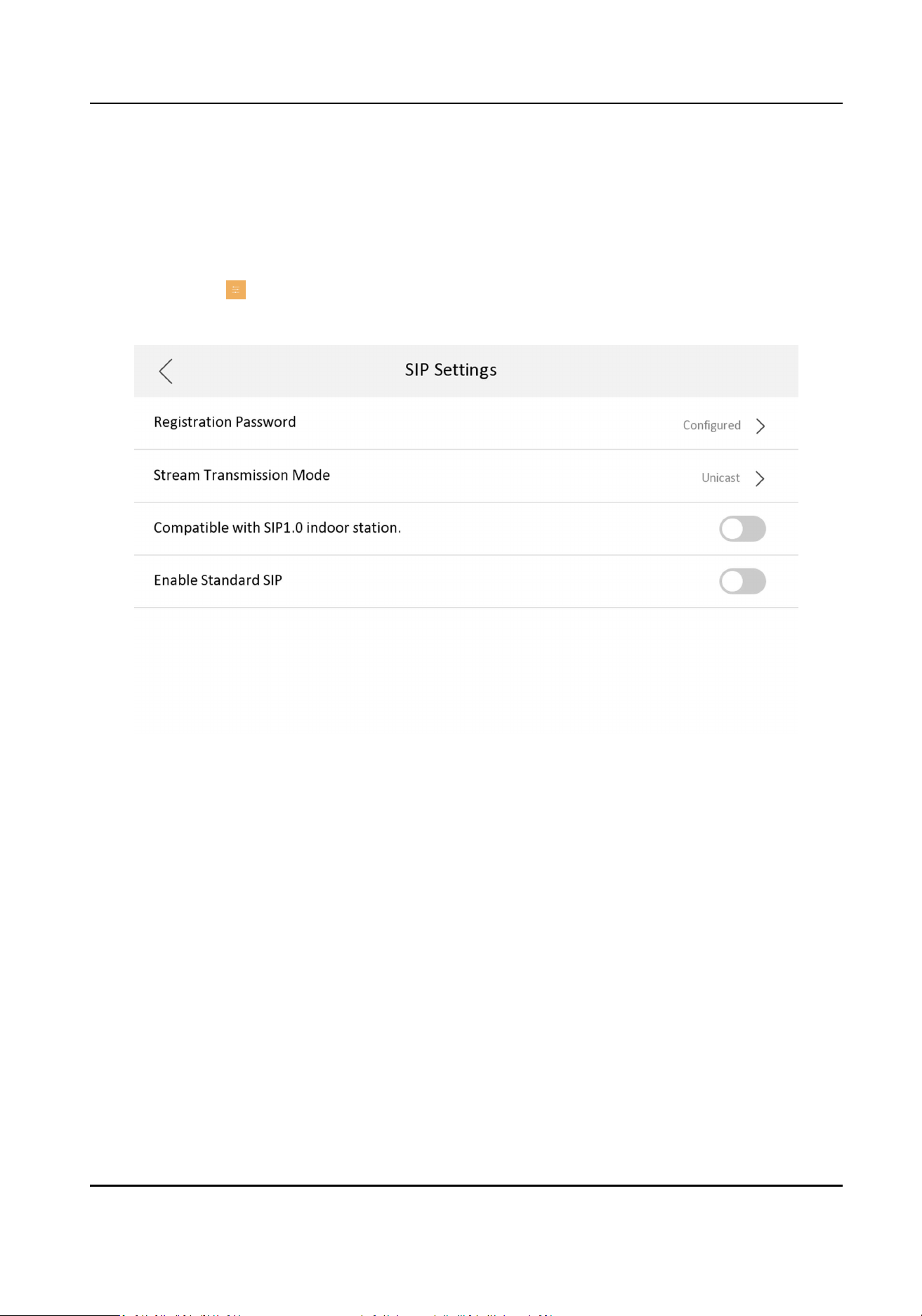
SIP Sengs
Devices can communicate with each other via SIP protocol. You create set the SIP register
password, enable standard SIP and set VOIP account.
Steps
1.
Tap Sengs → → Conguraon , and enter admin (acvaon) password.
2.
Tap SIP Sengs in Local Informaon Page.
Figure 7-16 SIP Sengs
3.
Set SIP registraon password.
1) Tap Registraon Password.
2) Create a new SIP registraon password and conrm the password.
3) Tap OK.
4.
Oponal: Enable standard SIP.
1) Slide to Enable Standard SIP.
2) Tap VOIP Account Sengs and congure the account informaon, including the user name,
the phone number, the registered user name, the password, the domain, the port No., and
the expiraon date.
Video Intercom Kit User Manual
31
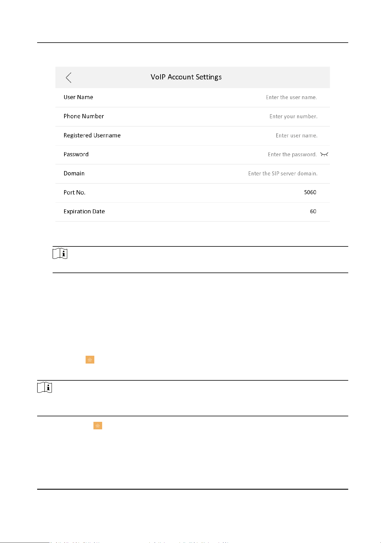
Figure 7-17 VOIP Account Sengs
Note
Up to 32 characters are allowed in the user name.
Zone and Alarm Sengs
Zone Sengs
You can set the zone type, alarm type and delay me and other parameters of 2 zones.
Before You Start
Tap Sengs → to enable Alarm.
Steps
Note
Arming status page and zone sengs page are hidden by default. You should enable alarm funcon
rst.
1.
Tap Sengs → → Zone Sengs to enter the zone sengs page.
Video Intercom Kit User Manual
32
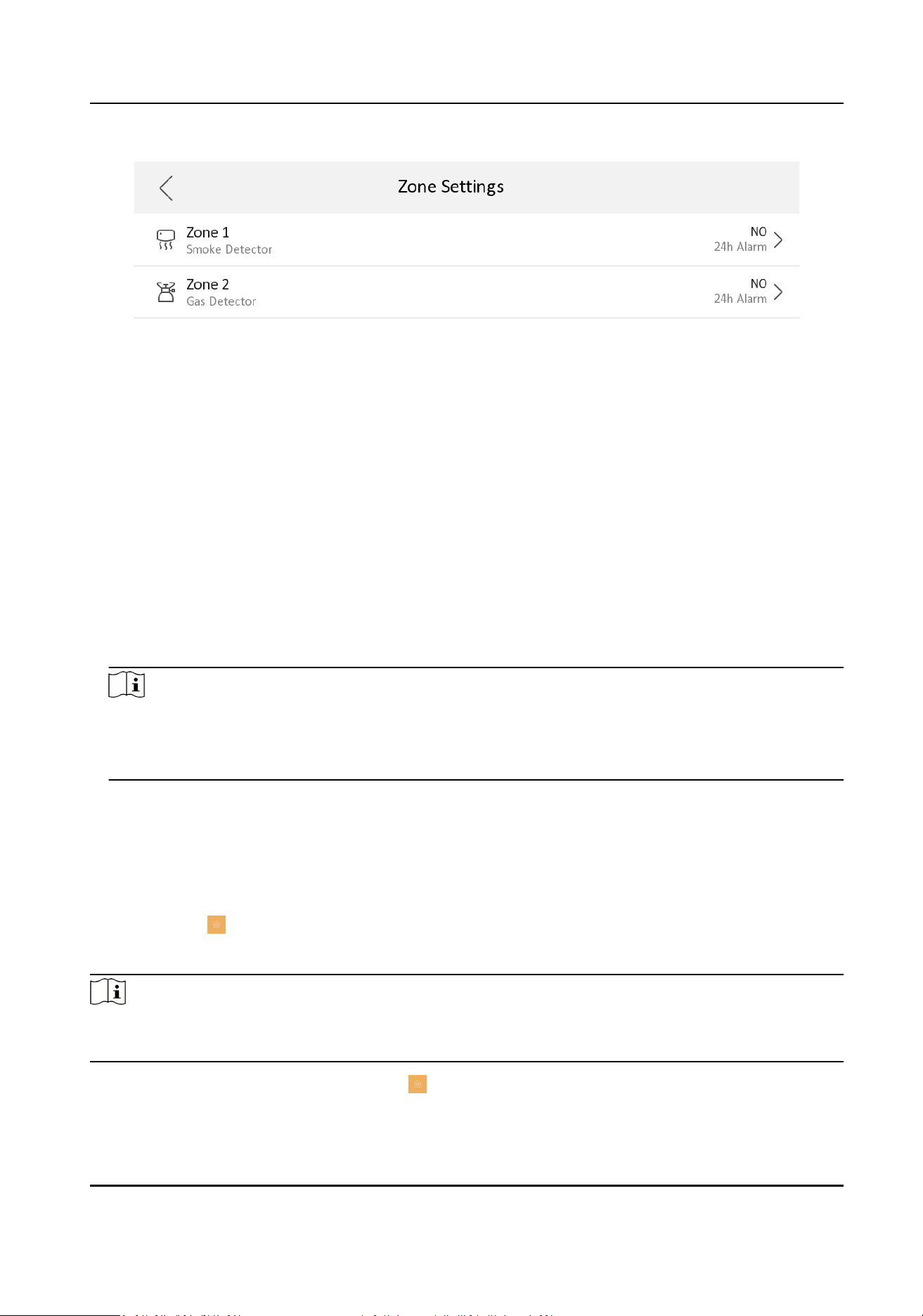
Figure 7-18 Zone Sengs
2.
Press a zone to pop up the zone eding dialogue box.
3.
Set the zone type, alarm type, status of arming status, entering delay, and exing delay.
4.
Tap OK to save the sengs.
Note
●
2 zone types are selectable: Smoke Detector and Gas Detector.
●
For Gas Detector and Smoke Detector, the alarm type is set as default 24h alarm. The alarm
type of them can not be changed.
Arming Mode Sengs
4 arming modes can be congured: stay mode, away mode, sleeping mode and custom mode.
Before You Start
Tap Sengs →
→ Shortcut Sengs to enable Alarm.
Steps
Note
On the home page, the arming status funcon and zone sengs funcon are hidden by default.
You should enable the alarm funcon rst.
1.
Back to the home page, tap Sengs → → Scene Sengs to enter the arming mode sengs
page.
Video Intercom Kit User Manual
33
2.
Tap Stay Mode, Away Mode, Sleeping Mode, or Custom to enter the page.
3.
Arm the selected zone.
Note
●
Zones are congurable on the arming mode page.
●
Smoke detector zone and gas detector zone will be triggered even if they are disabled.
7.1.3 Password Sengs
Modify Admin Password
You can reset admin password via reserved email or security quesons.
If you only set the email address or security quesons, the admin password can be reset via the
method you choose by default.
If you set both the email address and security quesons, you can choose either method to reset
the admin password.
Change by Email
You can change admin password via email.
Before You Start
●
The funcon of the device varies according to different models. Refers to the actual device for
detailed informaon.
●
You need to set a reserved email address at the wizard or tap Sengs → → Conguraon →
→ Security Sengs → Email Address to set or change the reserved email address.
Note
Admin password is required to enter the conguraon page.
Steps
1.
Tap Sengs → → Conguraon .
2.
Tap Forgot Password at the pop up window.
3.
Change your admin password via reserved email address.
Note
Make sure the device has added to the Hik-Connect account.
1) Download Hik-Connect app.
2) Go to More → Reset Device Password .
3) Scan the QR code on the device and a vericaon code will be popped up.
4) Enter the vericaon code on the device page.
Video Intercom Kit User Manual
34
5) Tap OK.
4.
Create a new password and conrm it.
5.
Tap OK.
Change by Security Queson
You can change admin password via security quesons.
Before You Start
You need to security quesons at the wizard or tap Sengs → → Conguraon → →
Security Sengs → Security Queson to set or change the answers to the quesons.
Note
Admin password is required to enter the conguraon page.
Steps
1.
Tap Sengs → → Conguraon .
2.
Tap Forgot Password at the pop up window.
3.
Answer the security quesons.
4.
Tap OK.
Modify Arm/Disarm Password
You can create and edit the arm/disarm password of the indoor staon.
Steps
1.
Tap Sengs → → Password to enter the sengs page.
2.
Tap Arm/Disarm Password. Create the indoor staon's arm/disarm password. You should enter
the arm/disarm password to enable or disable the funcon.
3.
When you slide to disable Scene Password, there is no needs to enter password during scene
mode switching.
Modify Unlock/Duress Code
You can create and edit the duress code and unlock password of the indoor staon.
Steps
1.
Tap Sengs →
→ Conguraon , and enter admin (acvaon) password.
2.
Tap → Password to enter the password sengs page.
3.
Tap Unlock Password or Duress Code to pop up the password sengs dialog box.
Unlock Password
Create the indoor staon's unlock password. If the device has connected to a lock, enter the
password to unlock.
Video Intercom Kit User Manual
35
Duress Code
When you are hijacked and forced to open the door, you can enter the duress code. An alarm
will be triggered to nofy the management center secretly.
Note
The duress code and the unlock password cannot be the same.
4.
Create a new password and conrm it.
5.
Tap OK to save the sengs.
Modify SIP Password
You can change the SIP password.
Steps
1.
Tap Sengs → → Conguraon , and enter admin (acvaon) password.
2.
Tap → SIP Sengs to enter the page.
3.
Tap Registraon Password to pop up the SIP registraon password sengs dialog box.
4.
Create a new password and conrm it.
5.
Tap OK to save the sengs.
7.1.4 Synchronize Time
Steps
1.
Tap Sengs → → Time and Date to enter the me synchronizaon page.
2.
Tap Date Format and Time Format to set the me format.
3.
Oponal: Tap Time to set me manually.
4.
Tap Sync Time.
Video Intercom Kit User Manual
36
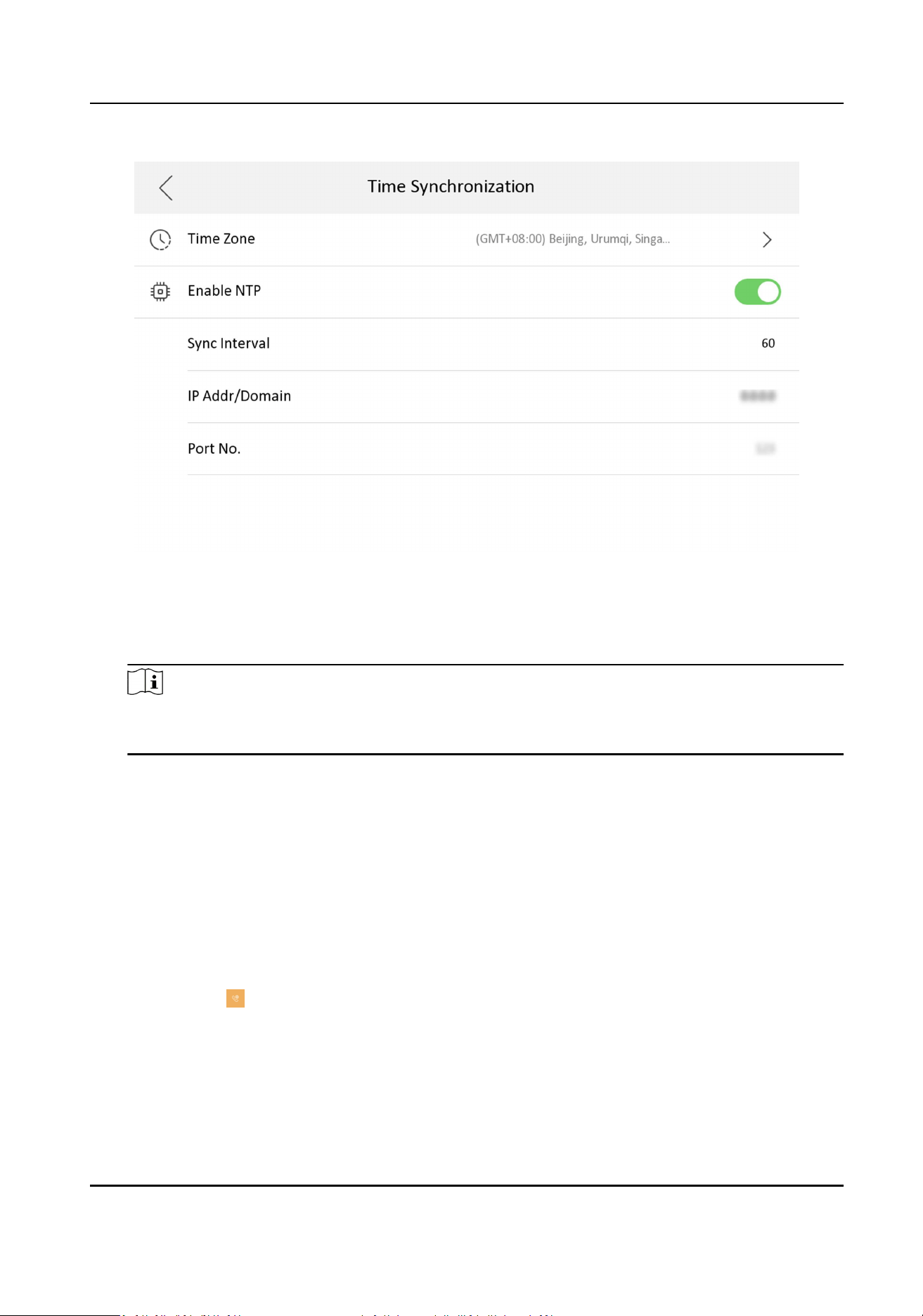
Figure 7-19 Time Synchronizaon
1) Select the Time Zone.
2) Enable Enable NTP.
3) Set the synchronizing interval, enter the IP address/domain of NTP server and port No.
Note
●
The default unit of synchronizing interval is minute.
●
The me zone can be congured as well if the NTP is not enabled.
7.1.5 Sound Sengs
Set the ringtone sound, the volume, and the auto answer.
Call Sengs
You can set the ringtone, ring duraon, call forwarding me on call sengs page.
Steps
1.
Tap Sengs → to enter the call sengs page.
Video Intercom Kit User Manual
37
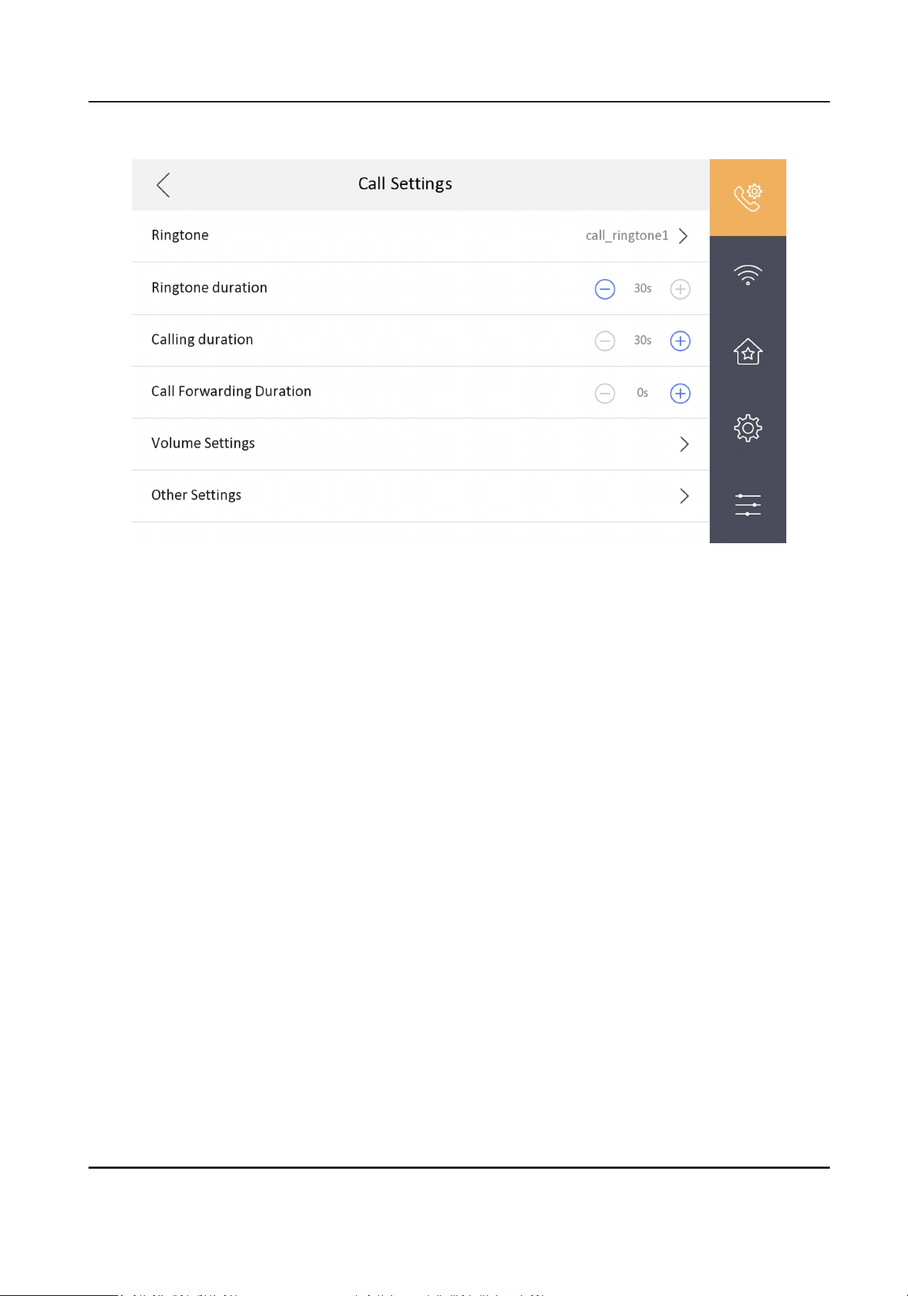
Figure 7-20 Call Sengs
2.
Set corresponding parameters.
Ringtone
There are 3 ringtones by default, and you can custom and import at most 4 ringtones via
Batch Conguraon Tool or iVMS-4200 Client Soware.
Ringtone Duraon: The maximum duraon of indoor staon when it is called without being
accepted. Ringtone duraon ranges from 30 s to 60 s.
Calling Duraon
The call will end automacally when the actual calling duraon is longer than the congured
one. Calling duraon ranges from 30 s to 60 s.
Call Forwarding Duraon
The ring duraon limit beyond which the call is automacally forwarded to the mobile phone
designated by the resident. Call forwarding ranges from 0 s to 20 s.
Other Sengs
You can set the Do Not Disturb and Auto-answer funcons.
Auto-answer
Enable Auto-answer. Aer enabling, the call from door staon/villa door staon will be
answered by the indoor staon automacally. The caller from door staon/villa door
staon can leave voice messages. Aer the message is le, you can check it from Message
on the main page of the device.
Video Intercom Kit User Manual
38
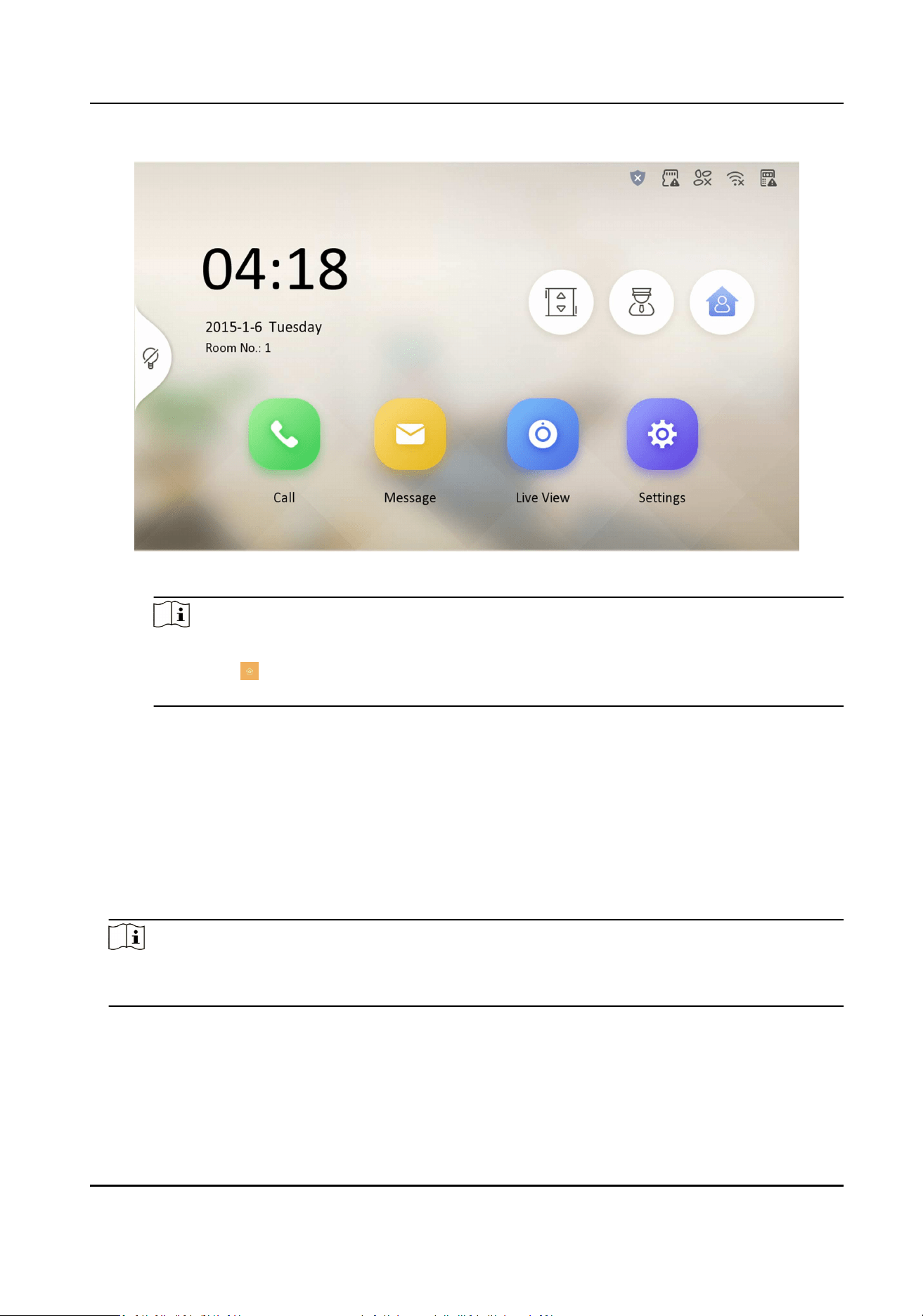
Figure 7-21 Main Page
Note
Before enabling Auto-answer, the funcon of Leave Message needs to be enabled. Tap
Sengs → → to enter the shortcut sengs page. Eanble Leave Message and go back to
calling sengs page to enable Auto-answer.
Do Not Disturb Device
Select All and all devices will not disturb this device. Select Indoor Staon and all indoor
staon will not disturb this device.
Do Not Disturb
Set the do not disturb schedule. Select Close and the do not disturb funcon will not be
enabled. Select All Day and this device will not be disturbed all day. Select Schedule and
you can set the do not disturb me duraon. Within the congured me, this device will
not be disturbed.
Note
Indoor extension does not support the ring duraon sengs, call forwarding sengs, or auto-
answer funcon.
Volume Sengs
Set the microphone volume, prompt sound volume, call volume, and enable touch sound.
Video Intercom Kit User Manual
39
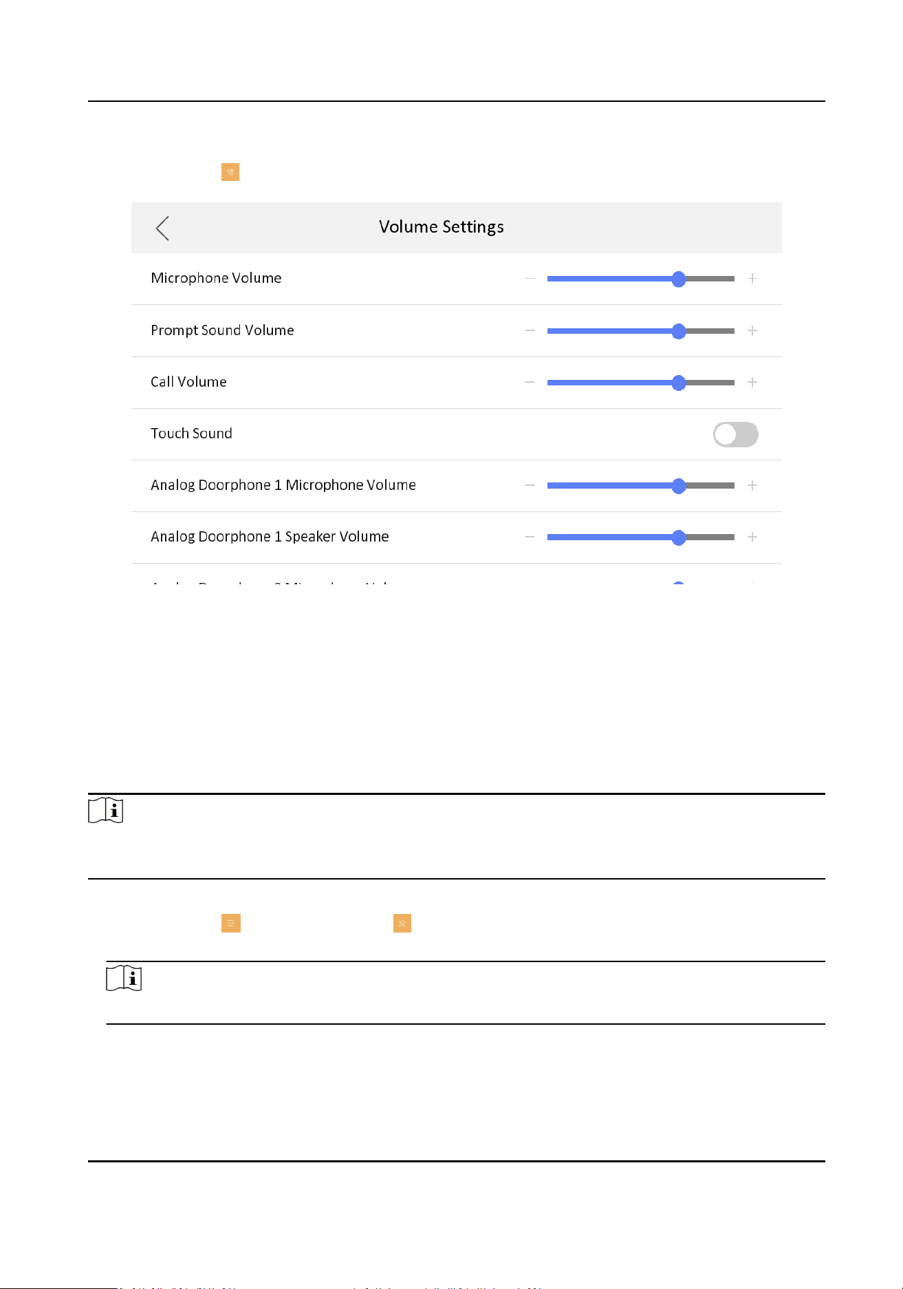
Steps
1.
Tap Sengs → → Volume Sengs to enter the volume sengs page.
Figure 7-22 Volume Sengs Page
2.
Set the microphone volume, prompt sound volume, and the call volume of the indoor staon.
Set the microphone volume and speaker volume for analog doorphone.
3.
Oponal: Enable Touch Sound to turn on the sound when you touch device screen.
7.1.6 Link to the Mobile Client
Before You Start
Note
The funcon of the device varies according to different models. Refers to the actual device for
detailed informaon.
Steps
1.
Tap Sengs → → Conguraon → → Hik-Connect Service Sengs to enter the sengs
page.
Note
Admin password is required to enter the conguraon page.
2.
Enable Enable Hik-Connect Service.
Video Intercom Kit User Manual
40
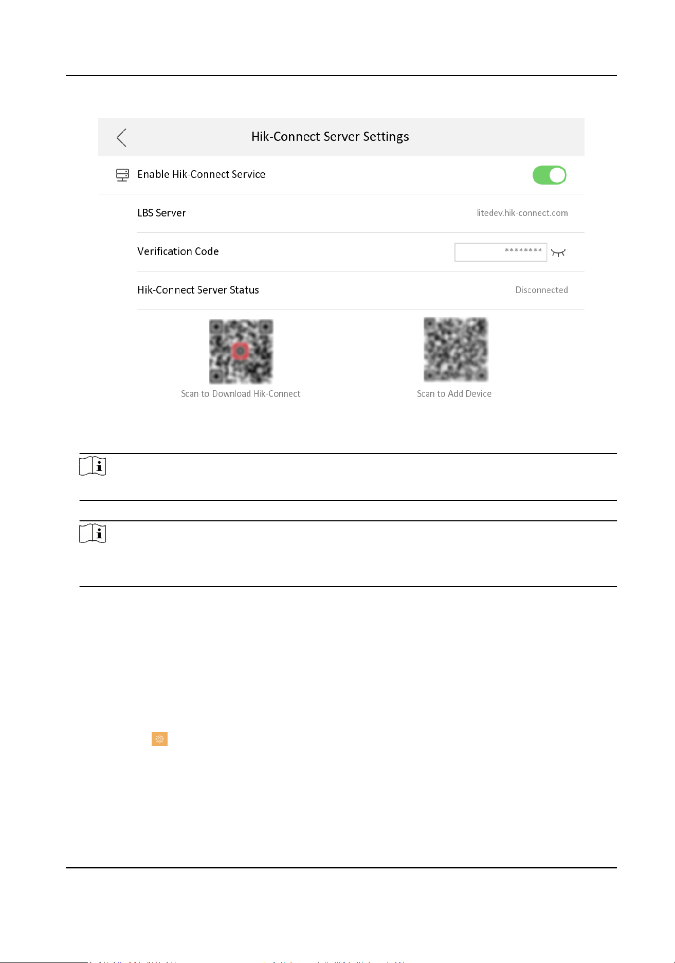
Figure 7-23 Enable Guarding Vision Service
3.
Edit LBS server and Vericaon Code.
Note
Vericaon code is used to add the device to mobile client.
4.
Oponal: Scan the QR code on the screen.
Note
●
Scan the le QR code on the screen to access Hik-Connect.
●
Scan the right QR code on the screen to add the device to the mobile client.
7.1.7 System Sengs
General Sengs
You can format or install TF card, clean the screen, set system language and adjust the screen
brightness on this page.
Tap Sengs → to enter the general sengs page.
Video Intercom Kit User Manual
41
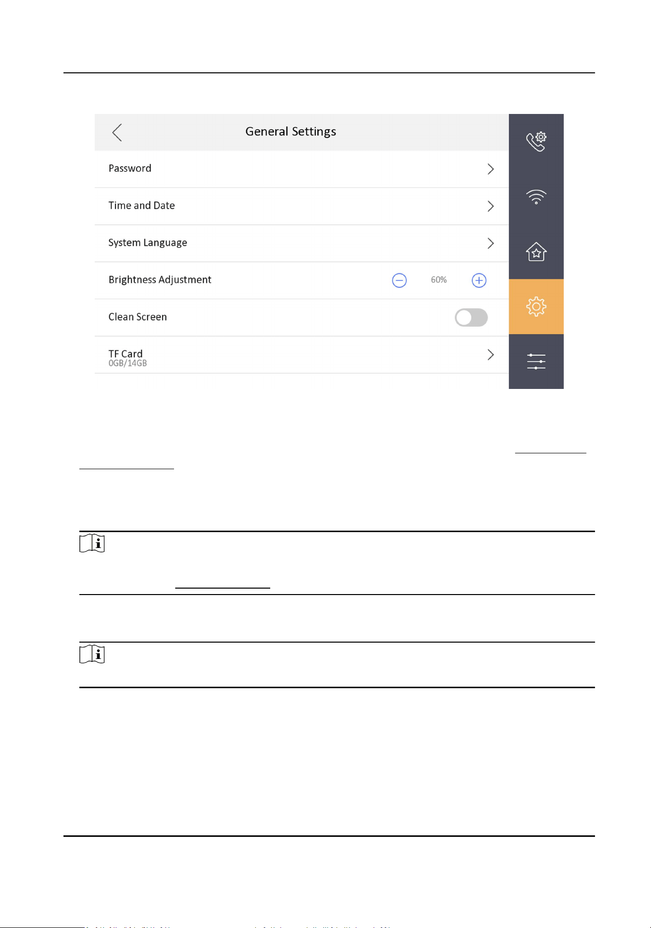
Figure 7-24 General Sengs Page
Password
You can manage your arm/disarm password and scene password. For details, see Modify Arm/
Disarm Password
Time and Date
You can set the displayed me and date format, current me. You can also tap Sync Time and
enable NTP to synchronize the device me.
Note
●
Make sure your device is connected with the network or the NTP funcon will not available.
●
For details, see Synchronize Time .
System Language
Tap System Language to change the system language.
Note
The indoor staon supports 11 languages.
Brightness Adjustment
Tap + or - to adjust the screen brightness.
Clean Screen
Enable Clear Screen and the screen will be locked for 30s. And you can clear the screen within
the me duraon.
Video Intercom Kit User Manual
42
Note
●
Aer enabling Clear Screen funcon, press and hold the Unlock key to exit the clear screen
mode.
●
The device without unlock key will exit the clear screen mode automacally when the me is
out.
TF Card
Tap TF Card to view the TF card and you can also format the TF card.
Maintenance
You can restore the device, upgrade system, unlink app account, set wizard, and congure security
sengs on the system maintenance page.
Tap Sengs → → Conguraon → to enter the system maintenance page.
Note
Admin password is required to enter the conguraon page.
Restore Default Sengs
Tap Restore Default Sengs to restore the default sengs and reboot the system.
Restore All
Tap Restore All to restore all parameters and reboot the system.
Upgrade
Tap Upgrade to get the upgrade package online.
Unlink APP Account
Tap Unlink APP Account to unlink the Hik-Connect account from the plaorm.
Note
The funcon of the device varies according to different models. Refers to the actual device for
detailed informaon.
Wizard
Tap Wizard and set the language, password reset method, network parameters, indoor staon
parameters, plaorm service, and related device. For details, refer to Quick Operaon .
Security Sengs
Tap Security Sengs and set the email address or security quesons for password reset.
Video Intercom Kit User Manual
43
Preference
You can congure zone sengs, scene sengs and shortcut sengs on the preference page.
Tap Sengs → to enter the preference page.
Zone Sengs
Note
Only when enable Alarm in the shortcut sengs, can the Zone Sengs displayed on the
Preference page.
Set the zone parameters. For details, see Zone Sengs .
Scene Sengs
Note
Only when enable Alarm in the shortcut sengs, can the Scene Sengs displayed on the
Preference page.
Set the scene parameters, including the stay mode, the away mode, the sleeping mode, or
customize the scene. For details, see Arming Mode Sengs .
Shortcut Sengs
Enable call elevator, alarm, call management center, leave message or snapshot and the icon
will be displayed on the home page.
You can set the leave message me and snapshot me if the two funcons are enabled.
7.1.8 Output Sengs
You can set and control the connected output devices via the output sengs page. You can change
the relay' name, and open duraon. You can also set to display the relay buon on the main page
or not.
Steps
1.
Tap Sengs →
→ Output Sengs .
Note
●
Supports up to 2 relays.
●
If no relays displayed on the page, the device may not support the funcon.
2.
Select a relay and set the parameters.
Name
You can change the relay's name.
Video Intercom Kit User Manual
44
Note
1 to 32 characters are allowed. Supports uppercase leers, lowercase leers, numerics, and
special characters.
Remain Open
Enable the funcon, the relay remains open.
Disabled the funcon, and you can set the remain open duraon.
Note
●
By default, the funcon is disabled.
●
1 to 180 s are available to set.
Hide on Main Page
Enable the funcon and the relay buon will be displayed on the main page. You can control
the relay status manually on the main page.
Disabled the funcon and the relay buon will no be displayed on the main page.
7.1.9 Device Informaon
View the device informaon, including the version, model, serial No. and open source disclaimer.
Steps
1.
Tap Sengs → → Device Informaon to enter the Device Informaon page.
2.
View the device version, model, and serial No.
3.
Oponal: Tap Open Source Disclaimer to view the OSS statement.
Video Intercom Kit User Manual
45
Chapter 8 Operaon
8.1 Local Operaon
8.1.1 Call Sengs
Add Contact
Steps
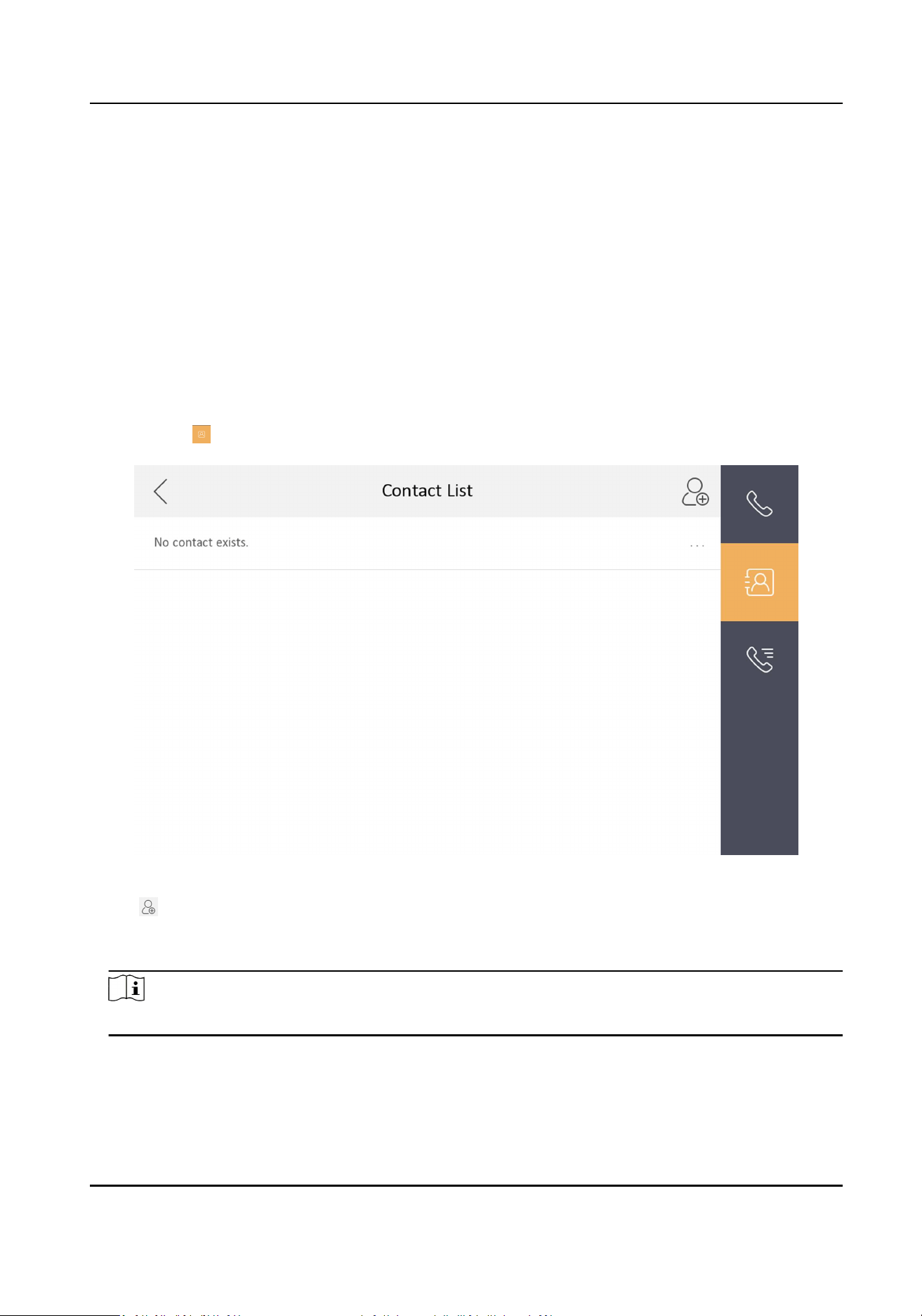
1.
Tap Call → to enter the contact list page.
Figure 8-1 Contact List
2.
Tap to pop up the contact adding dialog.
3.
Enter the contact name and the room No.
4.
Tap OK to save the sengs.
Note
Up to 200 contacts can be added.
Video Intercom Kit User Manual
46
Call Resident
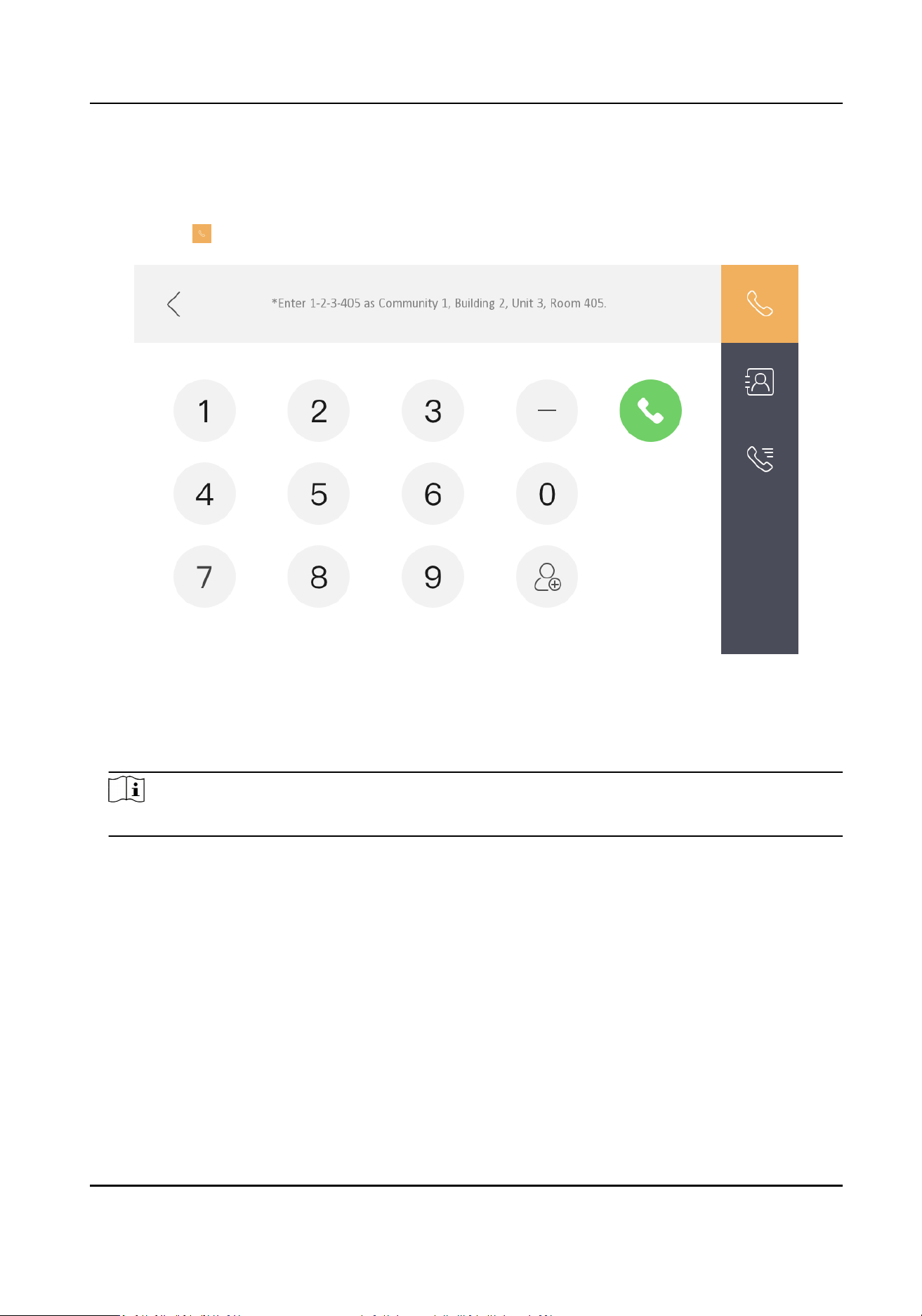
Steps
1.
Tap Call → to enter the residents calling page.
Figure 8-2 Call Resident
2.
Enter the calling number.
The calling number format should be x-x-x-xxx. For example, the calling number of Community 1,
Building 2, Unit 3, and Room 405 is 1-2-3-405.
Note
The community No. can be omied.
3.
Tap the call buon to start an audiovisual call.
Call Indoor Extension/Indoor Staon
If you install indoor staon and indoor extensions at home, you can call the indoor extension via
your indoor staon, and vice versa.
Enter 【0-indoor extension No.】 on the indoor staon to start calling.
Enter 【0-0】 to call the indoor staon from the indoor extension.
Video Intercom Kit User Manual
47
Receive Call
The indoor staon and indoor extension can receive calls from the analog doorphone, the door
staon, the main staon or iVMS-4200 Client.
On the call from door staon page, there are 2 unlock buons: Unlock 1, and Unlock 2. When you
tap Unlock 1, the building gate will open by default, and when you tap Unlock 2, the door
connected to the door staon with the secure control door unit will open.
Tap the capture buon to capture and save the live view picture when speaking with the door
staon.
On the call from the analog doorphone page, you can tap the unlock buon to open the connected
door lock and tap the capture buon to capture and save the live view pictures.
Note
●
The indoor extension can connect to indoor staon with network cables. Aer connecng, the
indoor extension can receive calls from devices that linked to the indoor staon.
●
The indoor extension can link to analog doorphones independently and receive calls from linked
doorphones.
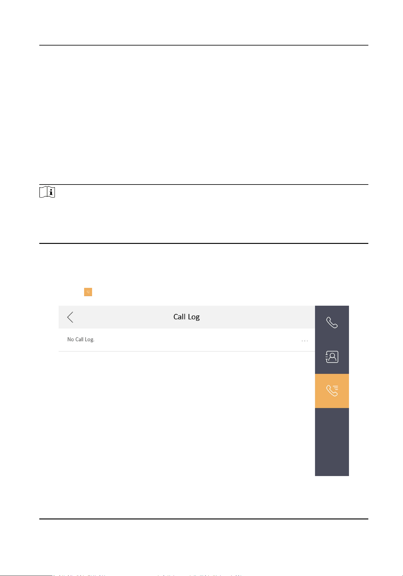
View Call Logs
Steps
1.
Tap Call → to enter the call log page.
Figure 8-3 Call Logs
Video Intercom Kit User Manual
48
2.
Tap a piece of call logs in the list to call back.
Note
●
The indoor staon saves call logs from analog doorphones, door staons, outer door staons,
management center and other indoor staons.
●
Hold a piece of call logs to open the call logs handling menu. Tap Delete to delete the piece of
call logs. Tap Clear to delete all pieces of call logs.
8.1.2 Leave Message
You can set leave message, and view the messages.
Tap Sengs → → Shortcut Sengs , and enable Leave Message.
Set Leave Message Time as 1 day, 7 days or 30 days.
Tap Message → to view the visitor messages.
8.1.3 Live View
On the live view page, you can view the live video of added door staon and network camera.
Steps
Note
●
Make sure the network camera or door staon is well-connected.
●
Make sure the indoor extension and the indoor staon are well-connected.
●
If the main indoor staon uses V2.2.4 or later rmware, and the indoor extension uses rmware
earlier than V2.2.4, there will be some restricon:
a. Indoor extension can only live view doorphone 1 and cannot live view doorphone 2. So it is
beer to use both indoor staon and extension with same model and rmware.
b. Indoor extension can only unlock doorphone1 and intercom funcon cannot be enabled in
live view page.
c. Analog doorphone and indoor extension cannot be live viewed in Hik-Connect App at the
same me.
d. When calling from analog doorphone, the main indoor staon will show the real number,
while the indoor extension will only show main doorphone in call log (in order to be compable
with the old version indoor extension) .
e. The indoor extension supports switching IPC when video intercoming with door staons but
the main indoor staon does not support. (Unblockable for compability with old versions.)
1.
Tap Live View to enter the live view page.
Video Intercom Kit User Manual
49
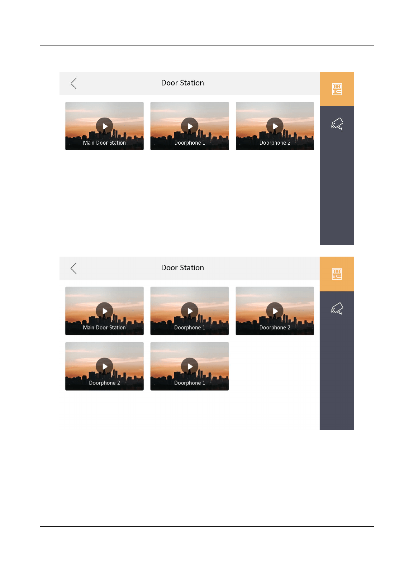
Figure 8-4 Live View
Video Intercom Kit User Manual
50
Note
●
The indoor extension can connect to indoor staon with network cables. Aer connecng, the
indoor extension can view related devices that linked to the indoor staon.
●
The indoor extension can link to analog doorphones independently and view linked
doorphones.
2.
Tap to enter the live view page of door staon.
Note
●
On the Call from Door Staon page, there are 2 unlock buons: Unlock 1, and Unlock 2. When
you tap Unlock 1, the building gate will open by default. When you tap Unlock 2, the door
staon connected door will open.
●
On the Call from Door Staon page, there are 1 capture buon. You can tap the buon to
capture the picture via door staon.
●
On the Call from Analog Doorphone page, there are 1 unlock buon and 1 capture buon.
You can tap the buons to unlock the connected door or capture pictures.
3.
Tap to enter the live view page of network cameras.
8.1.4 Arm/Disarm
The indoor staon has four kinds of scene modes: sleeping mode, stay mode, away mode, and
custom mode. You can arm or disarm your room in each scene mode manually. The selected scene
mode will be displayed on the main page of the indoor staon.
Note
You should create an Arm/Disarm Password rst.
Arm Room
Steps
Note
Only when the Alarm shortcut funcon is enabled, should the call center buon be displayed. For
details, see the conguraon guide.
1.
Tap on the home page to enter the scene page.
Video Intercom Kit User Manual
51
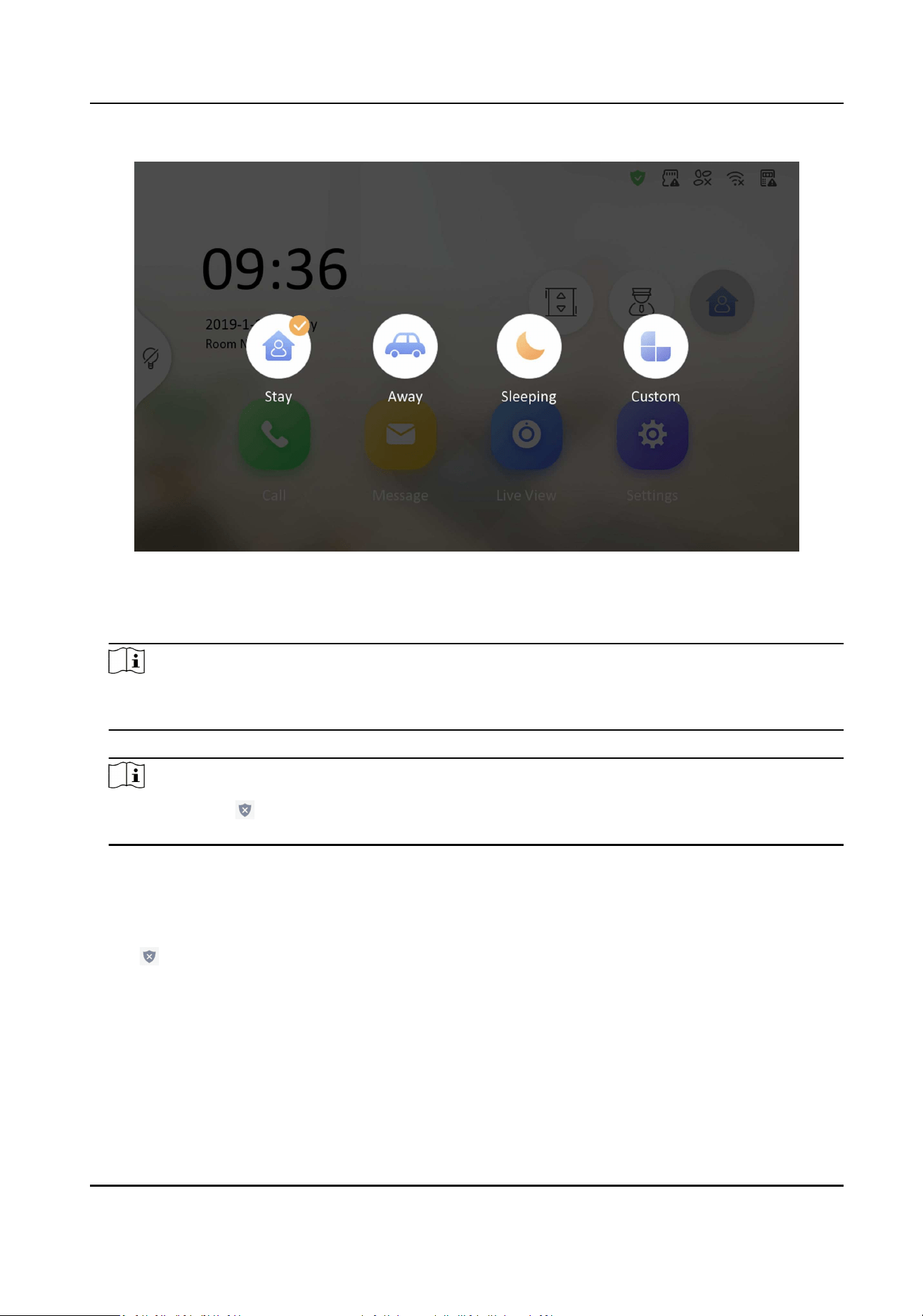
Figure 8-5 Arm Sengs page
2.
Select Stay, Away, Sleeping or Custom.
3.
Enter the arm/disarm password to enable the scene.
Note
You can set the arm/disarm password in the general sengs. For details, see the conguraon
guide.
4.
Tap OK.
Note
You can also tap → One-Push to Arm at the upper right corner of the home page to enable
the scene.
Disarm Room
Steps
1.
Tap → One-Push to Disarm at the upper-right corner of the home page to disarm.
Video Intercom Kit User Manual
52
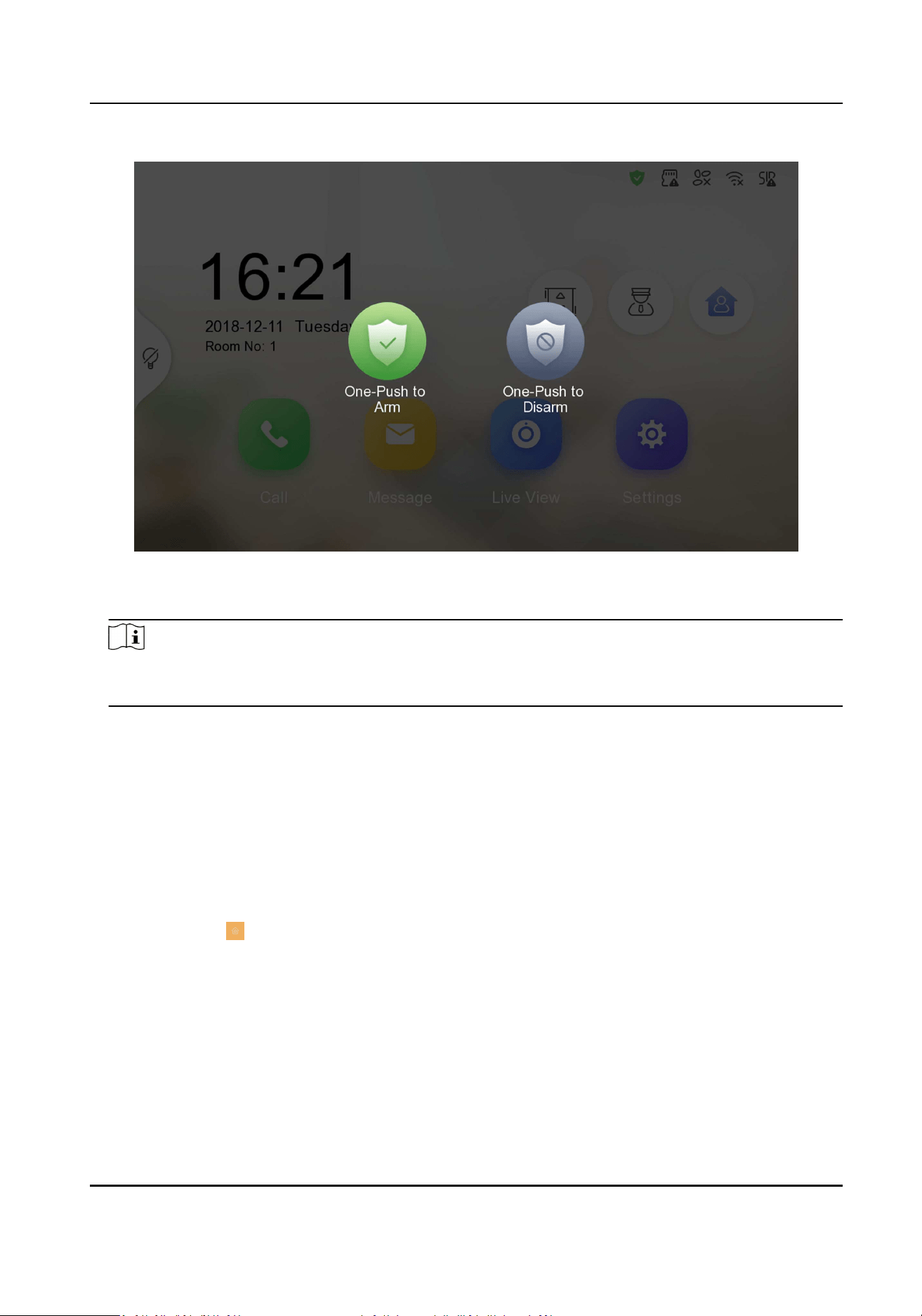
Figure 8-6 Disarm Room
2.
Enter the arm/disarm password.
Note
You can set the arm/disarm password in the general sengs. For details, see the conguraon
guide.
3.
Tap OK.
8.1.5 Call Elevator
The indoor staon supports calling the elevator.
Before You Start
Enable call elevator via iVMS-4200 Client Soware.
Steps
1.
Tap Sengs →
→ Shortcut Sengs to enable Call Elevator.
Video Intercom Kit User Manual
53
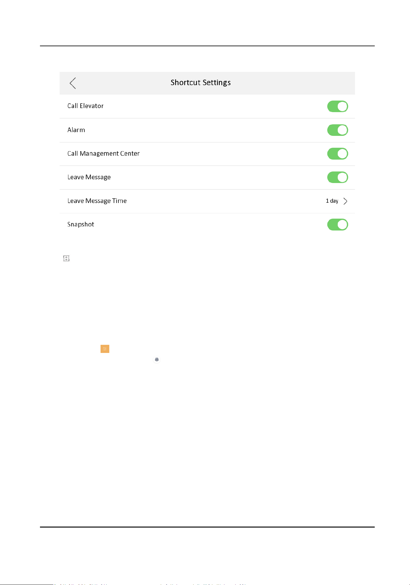
Figure 8-7 Call Elevator
2.
Tap on the home page of the indoor staon to start calling the elevator.
3.
When the device communicates with door staon, tap unlock icon to start calling the elevator.
8.1.6 Relay Sengs
Aer you set the output parameters and display the relay buon on the main page, you can
control the relay manually.
Steps
1.
Tap Sengs →
→ Output Sengs and disable Hide on Main Page funcon.
2.
Back to the main page and tap .
3.
Select a relay to enable or disable, the control device will start/stop working.
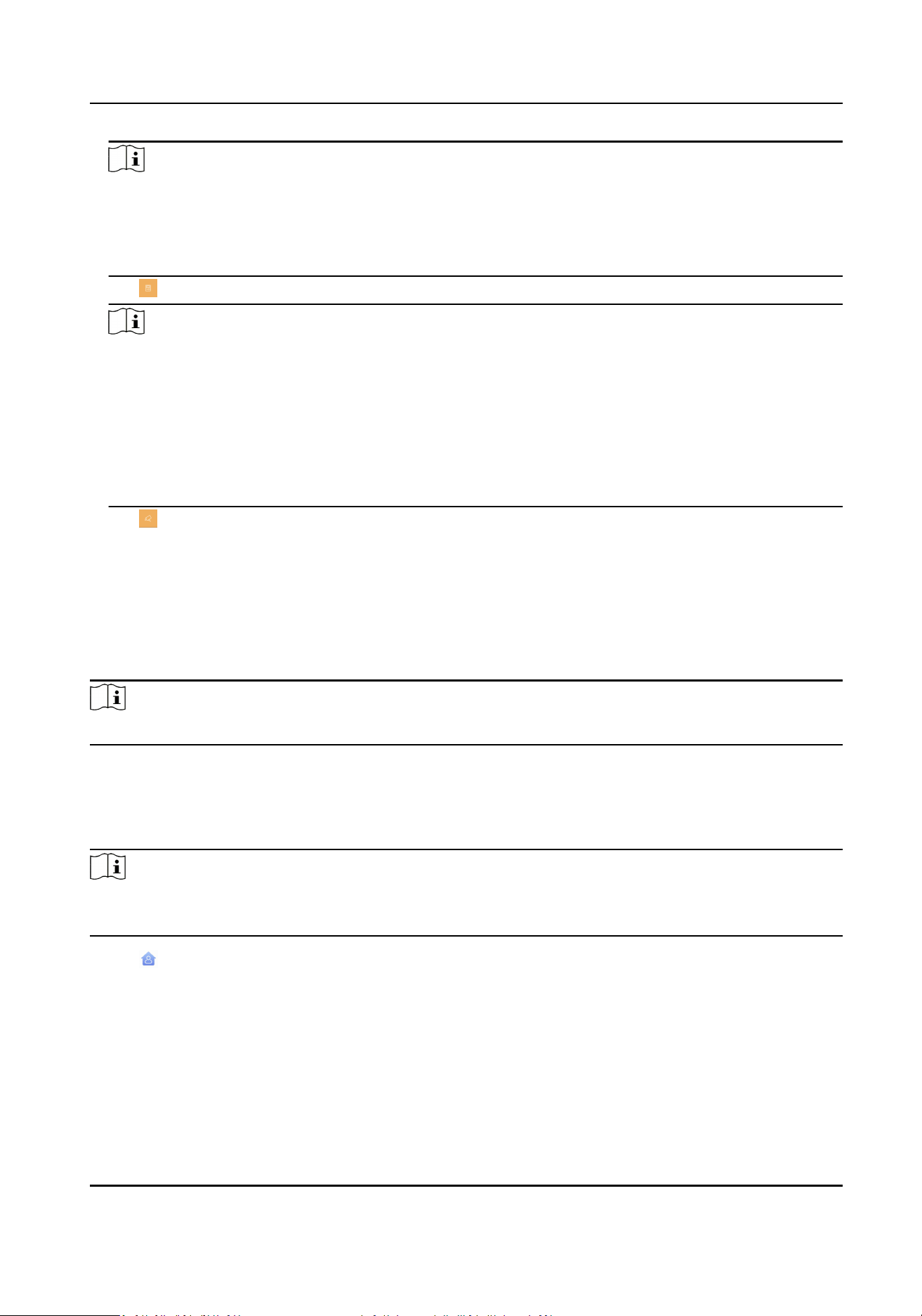
8.1.7 Informaon Management
You can view public noce, visitor message, alarm log and capture log on informaon management
page.
Tap Message on the home page to enter the informaon management page. (Here takes the alarm
log page as an example.)
Video Intercom Kit User Manual
54
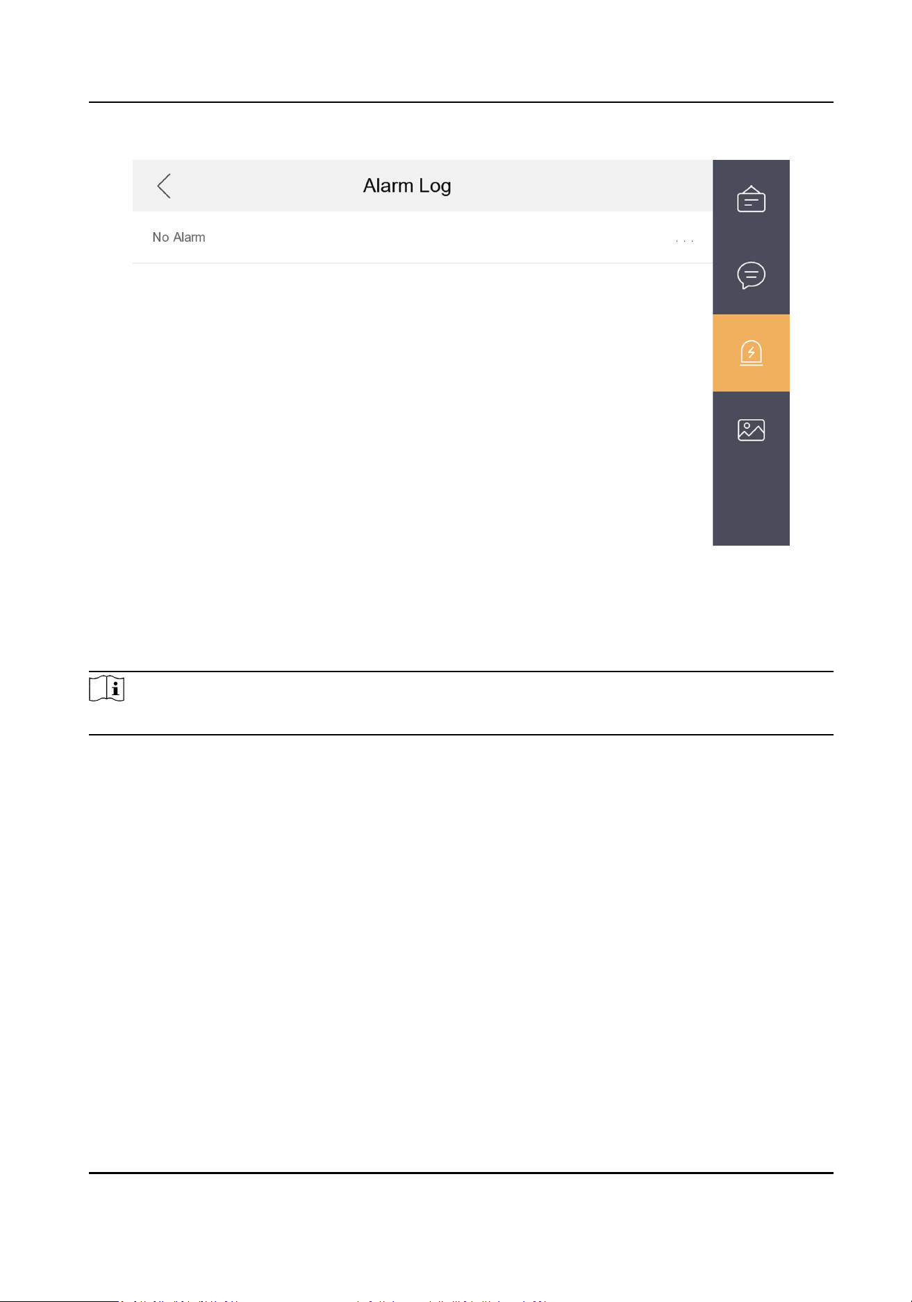
Figure 8-8 Alarm Logs
Delete a Log: Hold the item, you can delete it.
Clear Logs: Hold the item, you can clear all logs.
See Details: Hold a alarm log, you can see the alarm details.
Note
Indoor extension only supports alarm log and capture log.
Video Intercom Kit User Manual
55
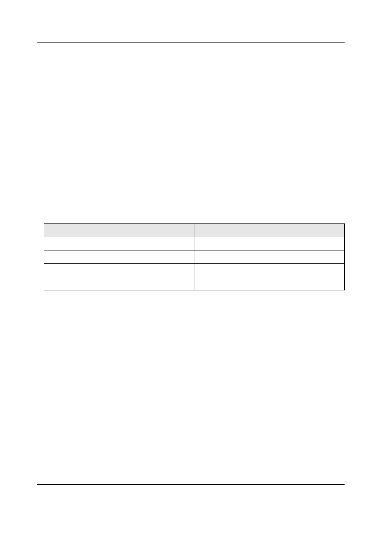
Appendix A. Cables
Cables and Wiring
●
When there are mulple cores in one parallel line, only one pair of closed cores are allowed to
transmit signal. It is not allowed to use mulple pair of cores in one cable to transmit signal.
●
When using parallel lines, it is suggested to use those with shielding layer. If dual core or mulple
core parallel lines without shielding layer are routed, stability of signal transmission can be
eected. You need to run a test before installaon.
●
Impedance of cable should not be over suggested value, or distributor cannot transmit enough
power to indoor staon or door staon.
●
Strong electricity and weak electricity cannot be wired in the same route, they need to be wired
separately and the distance should be more than 0.5 meter.
●
All the cables used need to follow the restricon in the following table.
Table A-1 Wiring Cables
RVV4 Cable Specicaon Transmission Distance (TD)
RVV4 (0.2 mm
2
) Transmission Distance ≤ 10 m
RVV4 (0.5 mm
2
) 10 m < Transmission Distance ≤ 30 m
RVV4 (0.75 mm
2
) 30 m < Transmission Distance ≤ 50 m
RVV4 (1.5 mm
2
) 50 m < Transmission Distance ≤ 100 m
Video Intercom Kit User Manual
56

UD34408B