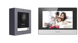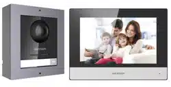

Module Door Staon
Conguraon Guide

Legal Informaon
User Manual
©2019 Hangzhou Hikvision Digital Technology Co., Ltd.
About this Manual
This Manual is subject to domesc and internaonal copyright protecon.
Hangzhou Hikvision Digital Technology Co., Ltd. ("Hikvision") reserves all
rights to this manual. This manual cannot be reproduced, changed,
translated, or distributed, parally or wholly, by any means, without the
prior wrien permission of Hikvision.
Please use this user manual under the guidance of professionals.
Trademarks
and other Hikvision marks are the property of
Hikvision and are registered trademarks or the subject of applicaons for
the same by Hikvision and/or its aliates. Other trademarks menoned in
this manual are the properes of their respecve owners. No right of license
is given to use such trademarks without express permission.
Disclaimer
TO THE MAXIMUM EXTENT PERMITTED BY APPLICABLE LAW, HIKVISION
MAKES NO WARRANTIES, EXPRESS OR IMPLIED, INCLUDING WITHOUT
LIMITATION THE IMPLIED WARRANTIES OF MERCHANTABILITY AND FITNESS
FOR A PARTICULAR PURPOSE, REGARDING THIS MANUAL. HIKVISION DOES
NOT WARRANT, GUARANTEE, OR MAKE ANY REPRESENTATIONS REGARDING
THE USE OF THE MANUAL, OR THE CORRECTNESS, ACCURACY, OR
RELIABILITY OF INFORMATION CONTAINED HEREIN. YOUR USE OF THIS
MANUAL AND ANY RELIANCE ON THIS MANUAL SHALL BE WHOLLY AT YOUR
OWN RISK AND RESPONSIBILITY.
REGARDING TO THE PRODUCT WITH INTERNET ACCESS, THE USE OF
PRODUCT SHALL BE WHOLLY AT YOUR OWN RISKS. HIKVISION SHALL NOT
Module Door Staon Conguraon Guide
i

TAKE ANY RESPONSIBILITIES FOR ABNORMAL OPERATION, PRIVACY
LEAKAGE OR OTHER DAMAGES RESULTING FROM CYBER ATTACK, HACKER
ATTACK, VIRUS INSPECTION, OR OTHER INTERNET SECURITY RISKS;
HOWEVER, HIKVISION WILL PROVIDE TIMELY TECHNICAL SUPPORT IF
REQUIRED.
SURVEILLANCE LAWS VARY BY JURISDICTION. PLEASE CHECK ALL RELEVANT
LAWS IN YOUR JURISDICTION BEFORE USING THIS PRODUCT IN ORDER TO
ENSURE THAT YOUR USE CONFORMS THE APPLICABLE LAW. HIKVISION
SHALL NOT BE LIABLE IN THE EVENT THAT THIS PRODUCT IS USED WITH
ILLEGITIMATE PURPOSES.
IN THE EVENT OF ANY CONFLICTS BETWEEN THIS MANUAL AND THE
APPLICABLE LAW, THE LATER PREVAILS.
Module Door Staon Conguraon Guide
ii
Symbol Convenons
The symbols that may be found in this document are dened as follows.
Symbol Descripon
Danger
Indicates a hazardous situaon which, if not avoided, will or
could result in death or serious injury.
Cauon
Indicates a potenally hazardous situaon which, if not
avoided, could result in equipment damage, data loss,
performance degradaon, or unexpected results.
Note
Provides addional informaon to emphasize or
supplement important points of the main text.
Module Door Staon Conguraon Guide
iii

Regulatory Informaon
FCC Informaon
Please take aenon that changes or modicaon not expressly approved
by the party responsible for compliance could void the user’s authority to
operate the equipment.
FCC compliance: This equipment has been tested and found to comply with
the limits for a Class B digital device, pursuant to part 15 of the FCC Rules.
These limits are designed to provide reasonable protecon against harmful
interference in a residenal installaon. This equipment generates, uses and
can radiate radio frequency energy and, if not installed and used in
accordance with the instrucons, may cause harmful interference to radio
communicaons. However, there is no guarantee that interference will not
occur in a parcular installaon. If this equipment does cause harmful
interference to radio or television recepon, which can be determined by
turning the equipment o and on, the user is encouraged to try to correct
the interference by one or more of the following measures:
—Reorient or relocate the receiving antenna.
—Increase the separaon between the equipment and receiver.
—Connect the equipment into an outlet on a circuit dierent from that to
which the receiver is connected.
—Consult the dealer or an experienced radio/TV technician for help
FCC Condions
This device complies with part 15 of the FCC Rules. Operaon is subject to
the following two condions:
1. This device may not cause harmful interference.
2. This device must accept any interference received, including interference
that may cause undesired operaon.
Module Door Staon Conguraon Guide
iv
EU Conformity Statement
This product and - if applicable - the supplied accessories too are
marked with "CE" and comply therefore with the applicable
harmonized European standards listed under the EMC Direcve
2014/30/EU, the RoHS Direcve 2011/65/EU
2012/19/EU (WEEE direcve): Products marked with this symbol
cannot be disposed of as unsorted municipal waste in the
European Union. For proper recycling, return this product to your
local supplier upon the purchase of equivalent new equipment, or
dispose of it at designated collecon points. For more informaon
see: www.recyclethis.info
2006/66/EC (baery direcve): This product contains a baery
that cannot be disposed of as unsorted municipal waste in the
European Union. See the product documentaon for specic
baery informaon. The baery is marked with this symbol,
which may include leering to indicate cadmium (Cd), lead (Pb),
or mercury (Hg). For proper recycling, return the baery to your
supplier or to a designated collecon point. For more informaon
see:www.recyclethis.info
Industry Canada ICES-003 Compliance
This device meets the CAN ICES-3 (B)/NMB-3(B) standards requirements.
Module Door Staon Conguraon Guide
v

Contents
1 Device Conguraon .................................................................................. 1
1.1 Acvate Device .................................................................................................. 1
1.2 Edit Network Parameters .................................................................................. 2
1.3 Add Device ........................................................................................................ 3
1.4 Reset Password ................................................................................................. 4
1.5 System ............................................................................................................... 5
1.6 Congure Video Intercom Parameters .............................................................. 9
1.6.1 Device ID Conguraon ............................................................................ 9
1.6.2 Time Parameters ..................................................................................... 10
1.6.3 Permission Password .............................................................................. 11
1.6.4 Access Control and Elevator ................................................................... 11
1.6.5 I/O Input and Output .............................................................................. 13
1.6.6 Volume Input and Output ....................................................................... 13
1.6.7 Dial .......................................................................................................... 14
1.6.8 Moon Detecon ................................................................................... 15
1.6.9 Intercom Protocol ................................................................................... 16
1.6.10 Sub Module .......................................................................................... 16
1.7 Congure Video Intercom Network ................................................................ 18
1.7.1 Local Network Conguraon .................................................................. 18
1.7.2 Linked Device Network Conguraon .................................................... 19
1.7.3 FTP .......................................................................................................... 20
1.7.4 Advanced Sengs .................................................................................. 21
Module Door Staon Conguraon Guide
vi

1.8 Person and Card Management ........................................................................ 22
1.8.1 Organizaon Management ..................................................................... 23
1.8.2 Person Management .............................................................................. 24
1.9 Video Display ................................................................................................... 33
1.9.1 Video Parameters ................................................................................... 33
1.9.2 Video & Audio ........................................................................................ 34
1.10 BLC Mode ...................................................................................................... 35
2 Video Intercom Operaon ........................................................................ 36
2.1 Video Intercom Operaon via Device ............................................................. 36
2.1.1 Call Resident ........................................................................................... 36
2.1.2 Issue Card ............................................................................................... 36
2.1.3 Unlock Door ............................................................................................ 37
2.2 Video Intercom Operaon via Client Soware ............................................... 38
2.2.1 Receive Call from Door Staon ............................................................... 38
2.2.2 Live View via Door Staon ...................................................................... 39
2.2.3 View Call Logs ......................................................................................... 40
2.2.4 Search Video Intercom Informaon ....................................................... 40
Module Door Staon Conguraon Guide
vii
1 Device Conguraon
1.1 Acvate Device
You can only congure and operate the door staon aer creang a password for
the device acvaon.
Default parameters of door staon are as follows:
•
Default IP Address: 192.0.0.65.
•
Default Port No.: 8000.
•
Default User Name: admin.
Steps
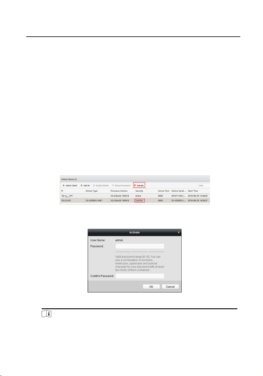
1.
Run the client soware, enter Device Management, check the Online Device
area.
2.
Select an inacvated device and click the Acvate.
Figure 1-1 Online Device Area
3.
Create a password, and conrm the password.
Figure 1-2 Acvate Device
Note
We highly recommend you to create a strong password of your own choosing
(using a minimum of 8 characters, including at least three kinds of following
categories: upper case leers, lower case leers, numbers, and special
Module Door Staon Conguraon Guide
1
characters) in order to increase the security of your product. And we
recommend you reset your password regularly, especially in the high security
system, reseng the password monthly or weekly can beer protect your
product.
4.
Click OK to acvate the device.
Note
•
When the device is not acvated, the basic operaon and remote operaon
of device cannot be performed.
•
You can hold the Ctrl or Shi key to select mulple devices in the online
devices, and click the Acvate buon to acvate devices in batch.
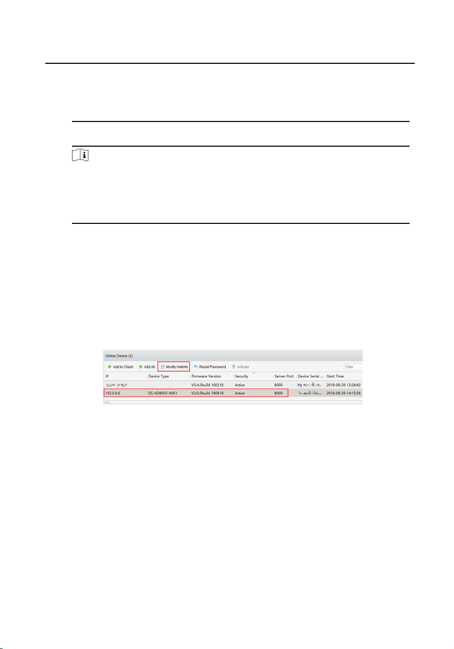
1.2 Edit Network Parameters
To operate and congure the device via LAN (Local Area Network), you need connect
the device in the same subnet with your PC. You can edit network parameters via
iVMS-4200 client soware.
Steps
1.
Select an online acvated device and click the Modify Nenfo.
Figure 1-3 Edit Network Parameters
2.
Edit the device IP address and gateway address to the same subnet with your
computer.
3.
Enter the password and click OK to save the network parameters modicaon.
Module Door Staon Conguraon Guide
2
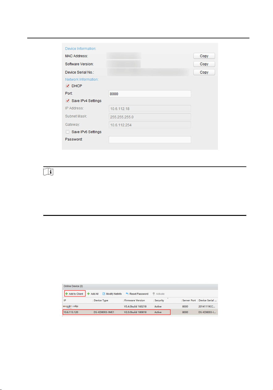
Figure 1-4 Modify Parameters
Note
•
The default port No. is 8000.
•
The default IP address of the door staon is 192.0.0.65.
•
Aer eding the network parameters of device, you should add the devices
to the device list again.
1.3 Add Device
To congure the device remotely, you need to add the device to iVMS-4200 client
soware.
Steps
1.
Select the acvated device and click Add to Client.
Figure 1-5 Add Device
2.
Enter corresponding informaon, and click Add.
Module Door Staon Conguraon Guide
3
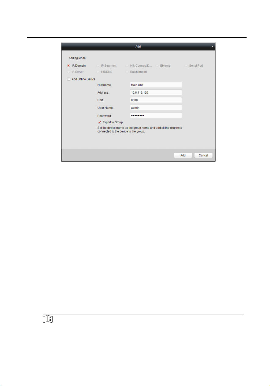
Figure 1-6 Add to the Client
1.4 Reset Password
You can restore the default password or reseng the password for the door staon.
Steps
1.
Select the device from the online device list, click Reset Password. If the window
with import le buon, key imporng mode drop-down list, password and
conrm password eld pops up.
2.
Click Export to save the device le on your computer.
3.
Send the le to our technical engineers.
4.
Our technical engineer will send you a le to you. Aer receiving a le from the
technical engineer, select Import File from Key Imporng Mode drop-down list
and click ... to import the le.
5.
Input new password in text elds of Password and Conrm Password.
6.
Click OK to reset the password.
Note
We highly recommend you to create a strong password of your own choosing
(using a minimum of 8 characters, including at least three kinds of following
categories: upper case leers, lower case leers, numbers, and special
Module Door Staon Conguraon Guide
4
characters) in order to increase the security of your product. And we
recommend you reset your password regularly, especially in the high security
system, reseng the password monthly or weekly can beer protect your
product.
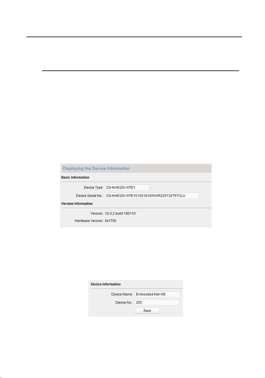
1.5 System
Click System on the remote conguraon page to display the device informaon:
Device Informaon, General, Time, System Maintenance, User, and RS-485.
Device Informaon
Click Device Informaon to enter device basic informaon page. You can
view basic informaon (the device type, and serial No.), and version
informaon of the device.
Figure 1-7 Device Informaon
General
Click General to enter device general parameters sengs page. You can
view and edit the device name and device ID.
Figure 1-8 General
Module Door Staon Conguraon Guide
5
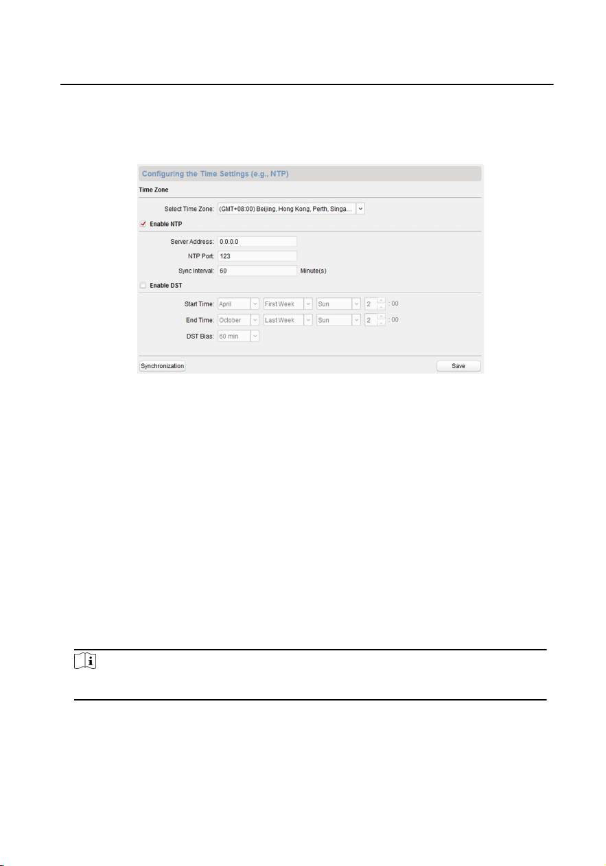
Time
Click Time to enter the device me sengs page.
Figure 1-9 Synchronize Time
Select Time Zone or Enable NTP. Click Save to save the me sengs.
•
Time Zone
-
Select a me zone from the drop-down list menu.
-
Click the Synchronizaon.
•
NTP
-
Check the checkbox of Enable NTP to enable NTP.
-
Enter the server address, NTP port, and synchronizaon interval.
•
DST
-
Check the checkbox of Enable DST to enable DST.
-
Enter the start me and end me of DST, and set the DST bias.
Note
The default port No. is 123.
System Maintenance
Click System Maintenance to enter the page.
Module Door Staon Conguraon Guide
6
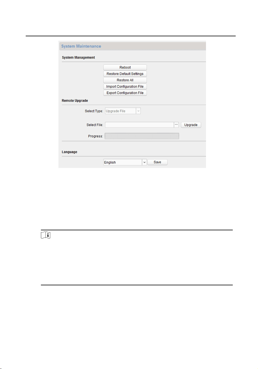
Figure 1-10 System Maintenance
•
Click Reboot and the system reboot dialog box pops up. Click Yes to
reboot the system.
•
Click Restore Default Sengs to restore the default parameters.
•
Click Restore All to restore all parameters of device and reset the device
to inacve status.
Note
-
Click Restore Default Sengs, all default sengs, excluding
network parameters, will be restored.
-
Click Restore All, all default sengs, including network
parameters, will be restored. The device will be reset to
inacvated status.
•
Click Import Conguraon File and the import le window pops up.
Select the path of remote conguraon les. Click Open to import the
remote conguraon le. The conguraon le is imported and the
device will reboot automacally.
Module Door Staon Conguraon Guide
7
•
Click Export Conguraon File and the export le window pops up.
Select the saving path of remote conguraon les and click Save to
export the conguraon le.
•
Click ... to select the upgrade le and click Upgrade to remote upgrade
the device. The process of remote upgrade will be displayed in the
process bar.
•
Select a language, and click Save to change the device system language.
Note
•
The device supports 5 languages: English, Russian, French, Portuguese,
and Spanish.
•
Reboong the device is required aer you change the system language.
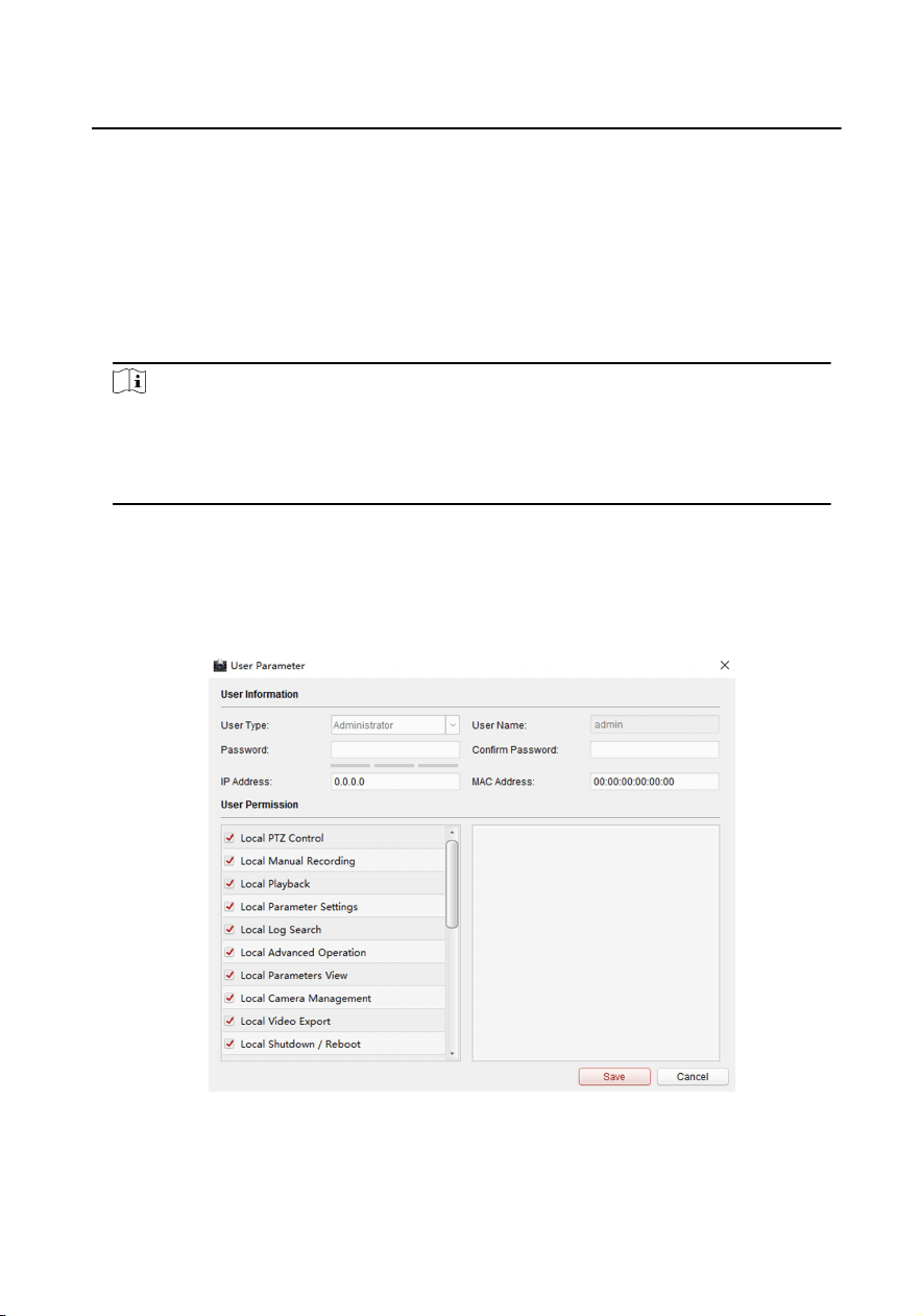
User
Click User to enter the user informaon eding page.
Select the user to edit and click Modify to enter the user parameter page.
Figure 1-11 User Page
Module Door Staon Conguraon Guide
8
Note
•
The new password and conrm password should be idencal.
•
Aer eding the password of device, click refresh buon from the
device list, the added device will not be there. You should add the device
again with new password to operate the remote conguraon.
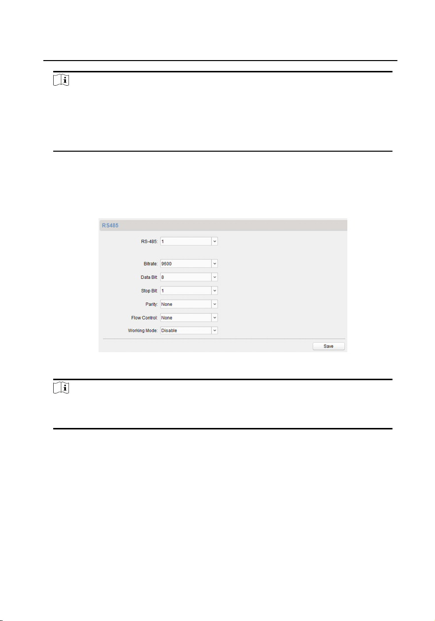
RS-485
Click RS485 to enter the RS-485 sengs page. You can view and edit the
RS-485 parameters of the device.
Figure 1-12 RS-485 Sengs
Note
For indoor staon and master staon, there are 3 choices for the working
mode: transparent channel, disable, and custom.
1.6 Congure Video Intercom Parameters
Click Video Intercom on the remote conguraon page to enter the video intercom
parameters sengs: Device Number Conguraon, Time Parameters, Access and
Elevator Control, IO Input/Output, Volume, Dial, Sub Module and so on.
1.6.1 Device ID Conguraon
Module Door Staon Conguraon Guide
9
Steps
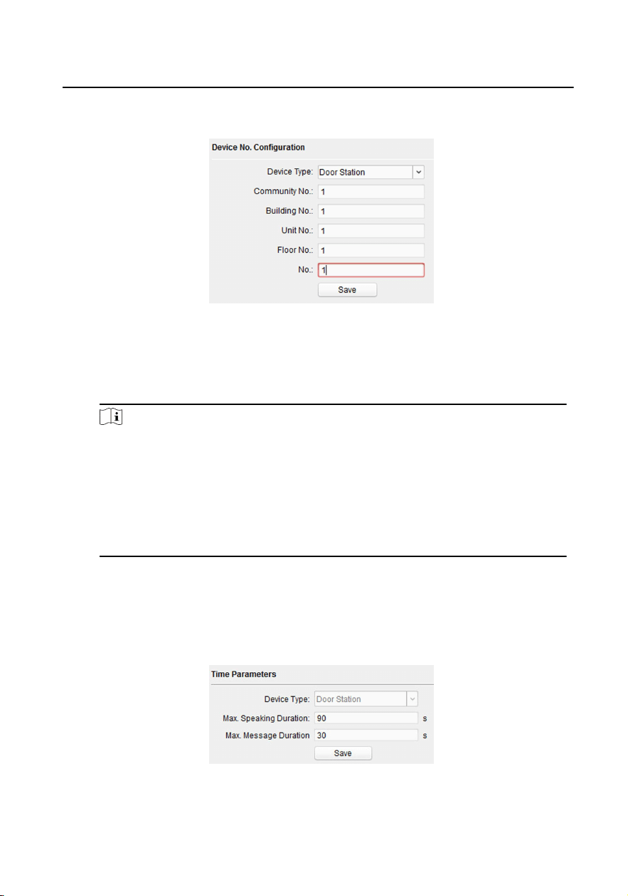
1. Click ID Conguraon to enter the device ID conguraon page.
Figure 1-13 Device No. Conguraon
2.
Select the device type from the drop-down list, and set the corresponding
informaon.
3.
Click Save to enable the device number conguraon.
Note
•
For main door staon, the serial No. is 0.
•
For sub door staon, the serial No. is higher than 0. Serial No. ranges from 1
to 99.
•
For each villa or building, at least one main door staon should be
congured, and sub door staons can be customized.
•
For one main door staon, at most 8 sub door staons can be customized.
1.6.2 Time Parameters
Steps
1.
Click Time Parameters to enter me parameters sengs page.
Figure 1-14 Time Parameters
Module Door Staon Conguraon Guide
10
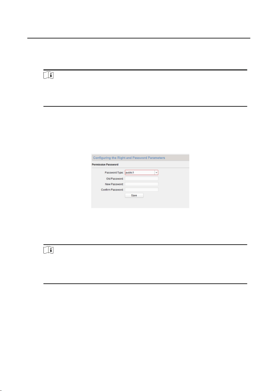
2. Congure the maximum ring duraon, maximum live view me, and call
forwarding me.
3.
Click Save.
Note
For door staon, maximum speaking me and maximum message me should
be congured. Maximum speaking me varies from 90 s to 120 s, and maximum
message me varies from 30 s to 60 s.
1.6.3 Permission Password
Steps
1.
Click Permission Password to enter the permission password page.
Figure 1-15 Permission Password
2.
Edit the password accordingly.
3.
Click Save to enable the sengs.
Note
•
You can congure 3 public passwords.
•
You can open the door by enterng # + public password + # at the door
staon.
1.6.4 Access Control and Elevator
Before You Start
•
Make sure your door staon is in the mode of main door staon. Only the main
door staon support elevator control funcon.
•
Connecon between the door staon and the elevator controller supports
network interface.
Module Door Staon Conguraon Guide
11
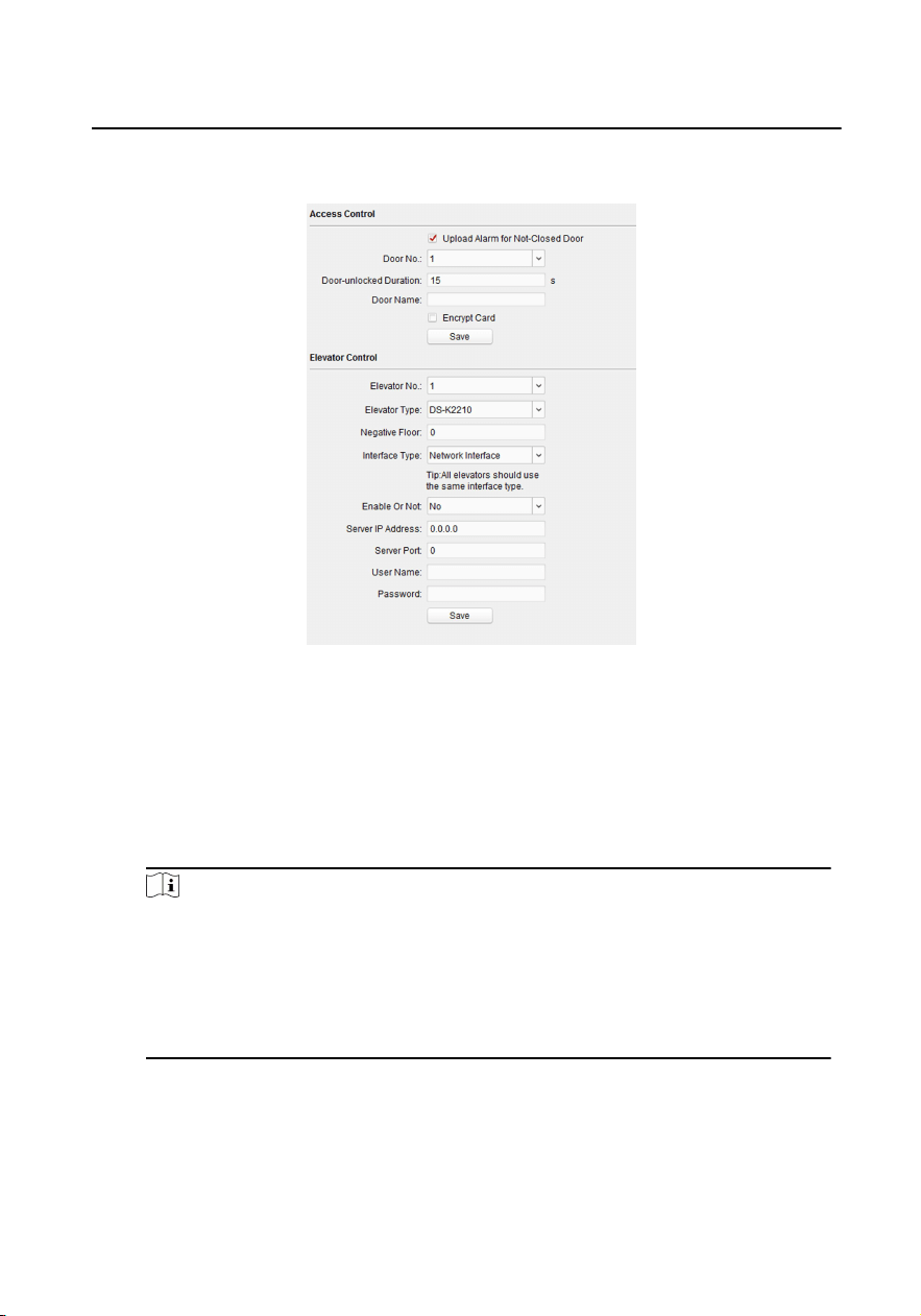
Steps
1. Click Access Control and Elevator to enter corresponding conguraon page.
Figure 1-16 Access Control and Elevator
2.
Set the Access Control parameters.
1) Select the door No.
2) Set the Door-unlocked Duraon.
3) Oponal: Enable Upload Alarm for Not-Closed Door.
4) Click Save to enable the sengs.
Note
•
The door-unlocked duraon ranges from 1 s to 255 s.
•
If you check Upload Alarm for Not-Closed Door, an alarm will be triggered
automacally if the door is not locked in the congured duraon.
•
Enabling Card Encrypt, the door staon can recognize the encrypted
informaon of the card when you swiping the card on the door staon.
3.
Set the Elevator Control parameters.
1) Select an elevator No., and select an elevator controller type for the elevator.
2) Set the negave oor.
Module Door Staon Conguraon Guide
12
3) Select network interface as interface type. Enter the elevator controller's IP
address, port No., user name, and password.
4) Enable the elevator control.
Note
•
Up to 4 elevator controllers can be connected to one door staon.
•
Up to 10 negave oors can be added.
•
Make sure the interface types of elevator controllers, which are connected
to the same door staon, are consistent.
1.6.5 I/O Input and Output
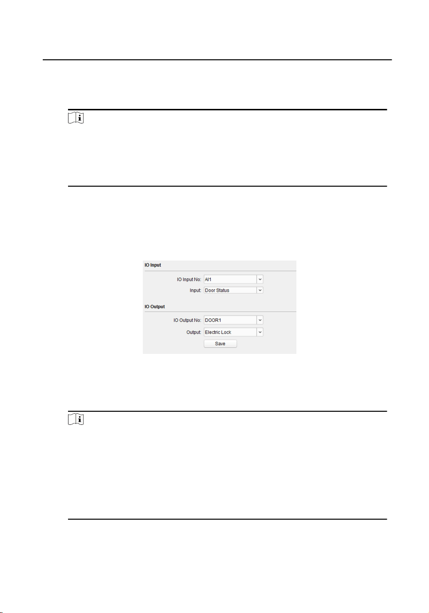
Steps
1.
Click I/O Input and Output to enter the I/O input and output sengs page.
Figure 1-17 I/O Input and Output
2.
Select I/O input No., input mode, output No., and output mode.
3.
Click Save to enable the sengs.
Note
•
For door staon, there are 4 I/O input terminals. By default, Terminal 1 and 2
correspond to Door Status. Terminal 3 and 4 correspond to interfaces of
Door Switch.
•
For door staon, there are 2 I/O Output Terminals. Terminal 1 and 2
correspond to DOOR interfaces (NO1/COM/NC1; NO2/COM/NC2) of door
staon. Door 1 is enabled by default. You can enable/disable IO Out
according to needs.
1.6.6 Volume Input and Output
Module Door Staon Conguraon Guide
13
Steps
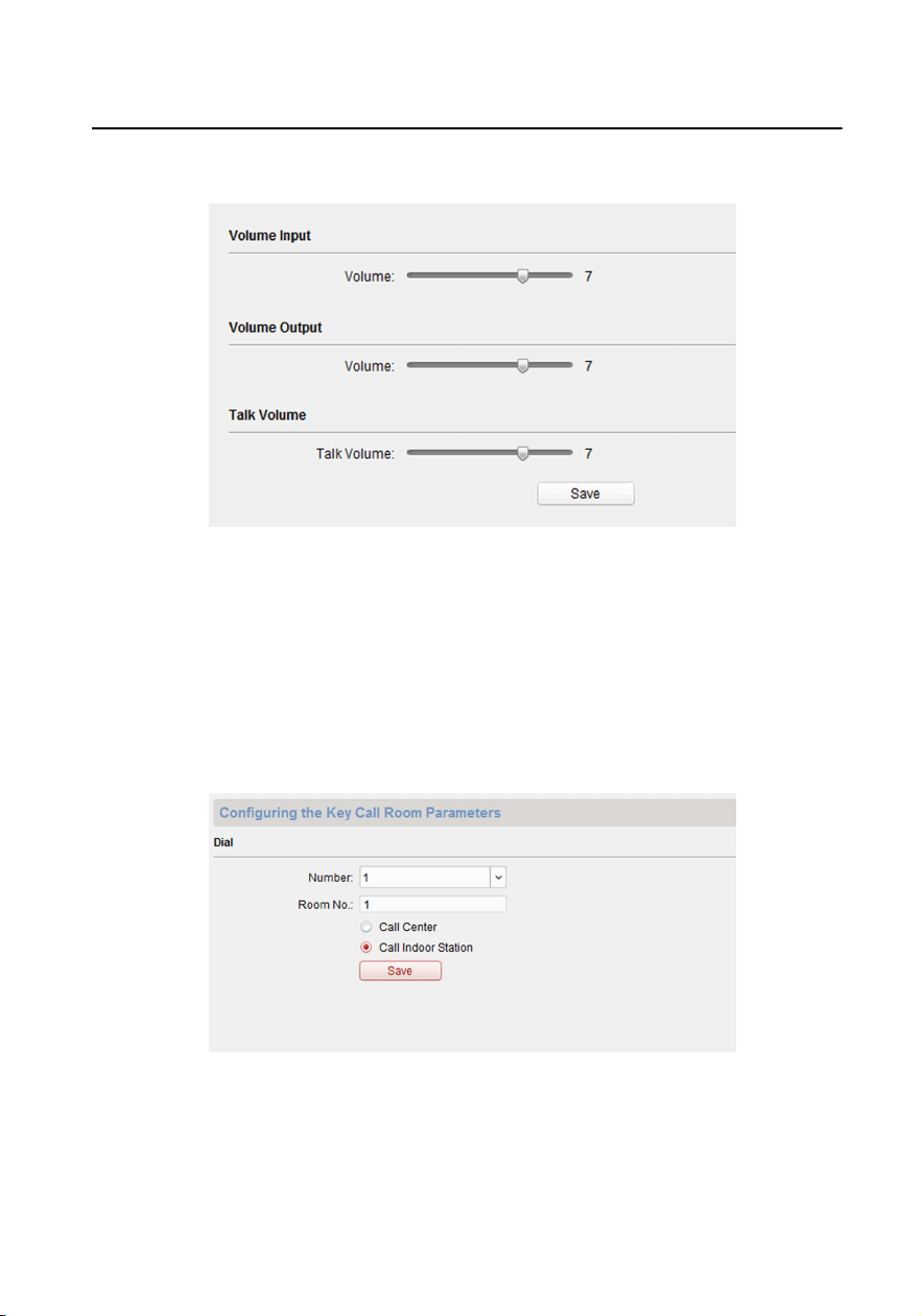
1. Click Volume Input/Output to enter the volume input and output page.
Figure 1-18 Volume Input and Output
2.
Slide the slider to adjust the volume input, volume output, and talk volume.
3.
Click Save to enable the sengs.
1.6.7 Dial
Steps
1.
Click Dial to enter the dial page.
Figure 1-19 Dial (Private SIP)
Module Door Staon Conguraon Guide
14
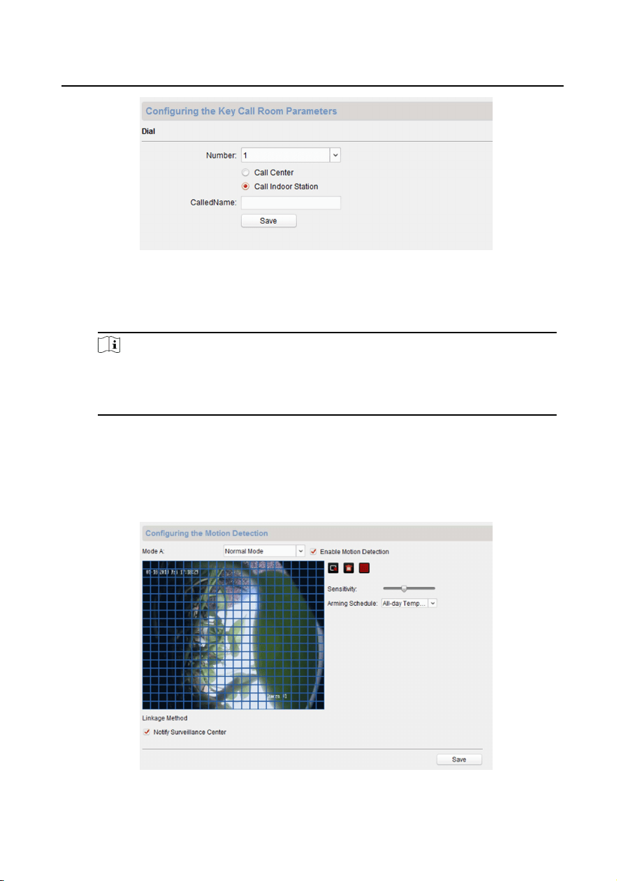
Figure 1-20 Dial (Standard SIP)
2. Enter the room No. of the indoor staon that the door staon connected to.
3.
Click Save to enable the sengs.
Note
By default, quick press the call buon, the door staon calls resident. If you
check Quick Press for Calling Center, the door staon calls the management
center when quick press the call buon of the main unit.
1.6.8 Moon Detecon
Steps
1.
Click Moon Detecon to enter the moon detecon page.
Figure 1-21 Moon Detecon
Module Door Staon Conguraon Guide
15

2. Enable Enable Moon Detecon.
3.
Congure the parameters.
4.
Click Save.
Note
The arming schedule is defaulted as all-day.
1.6.9 Intercom Protocol
Steps
1.
Click Intercom Protocol to enter the intercom protocol page.
2.
Select the protocol according to needs.
3.
Click Save.
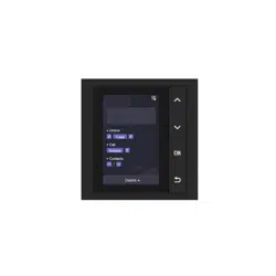
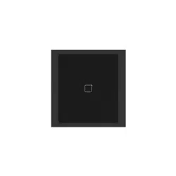
1.6.10 Sub Module
You can congured the room No. of nametag module and adjust the backlight of the
display module.
Steps
1.
Click Sub Module to enter the sub module conguraon page.
Module Door Staon Conguraon Guide
16
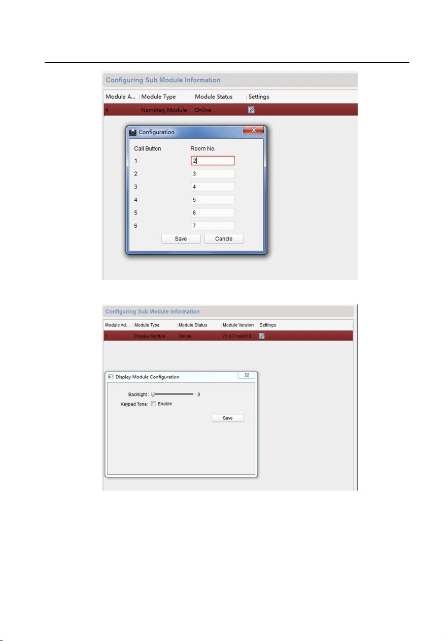
Figure 1-22 Nametag Module
Figure 1-23 Display Module
2.
Oponal: Enter the Room No. for each call buon of the nametag module.
3.
Adjust the Backlight of the display module.
4.
Oponal: Enable Keypad Tone.
5.
Click Save.
Module Door Staon Conguraon Guide
17
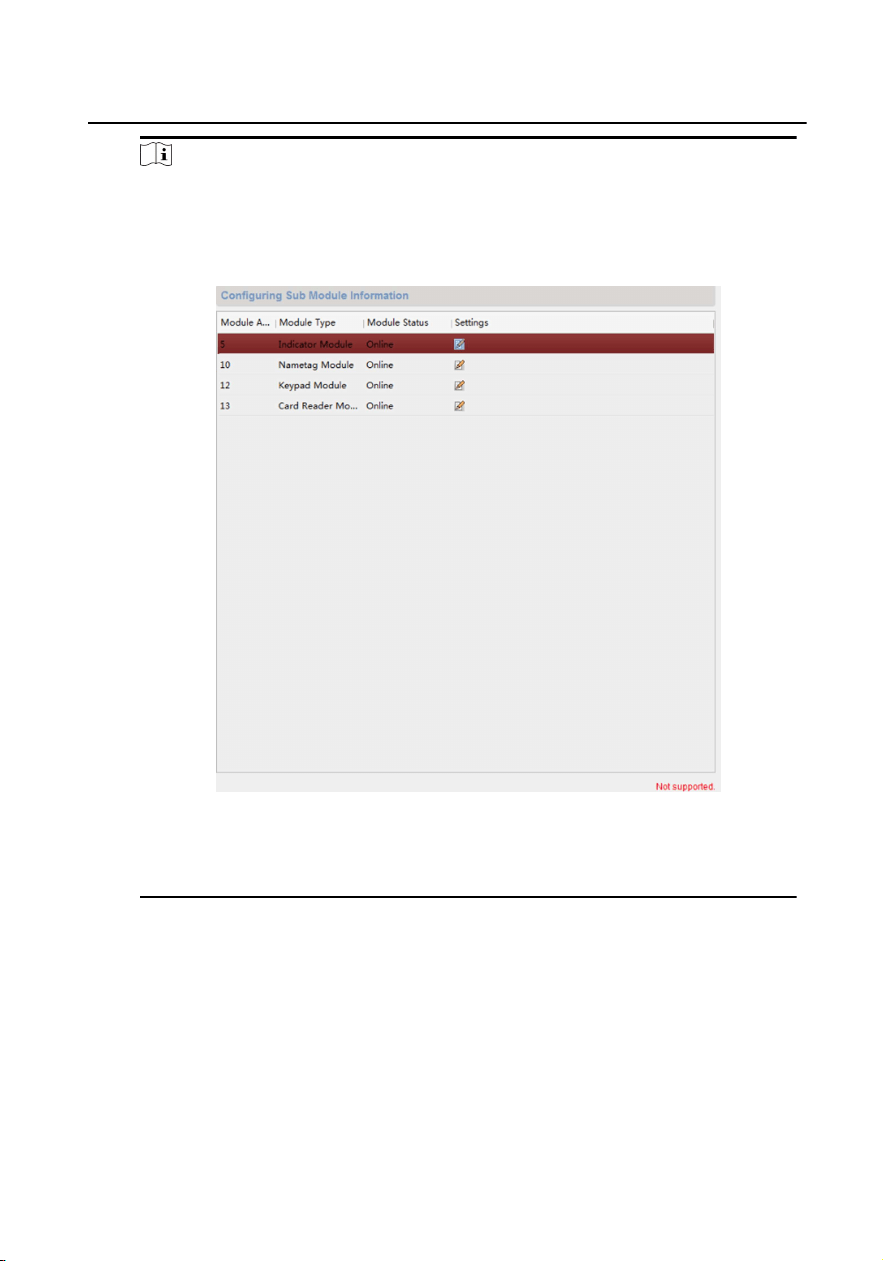
Note
•
The module address is used to dierenate the sub modules. See Congure
Sub Module Address for detailed conguraon instrucons.
•
For the other sub modules (indicator module, keypad module, display
module and card reader module), it prompts Not supported.
Figure 1-24 Conguring Sub Module Informaon
•
The room No. for the main unit's call buon is 1 by default; and the room
No. for the nametag modules call buons are 2 to 7 by default.
1.7 Congure Video Intercom Network
You need to congure video intercom network parameters in the network module.
Click Network in the remote conguraon interface, to congure the local network,
linked network and FTP sengs.
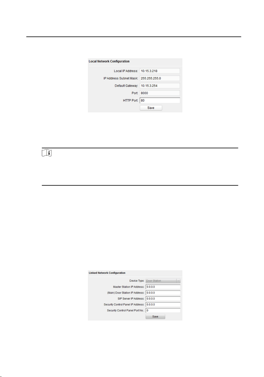
1.7.1 Local Network Conguraon
Module Door Staon Conguraon Guide
18
Steps
1. Click Local Network Conguraon to enter local network conguraon page.
Figure 1-25 Local Network Conguraon
2. Enter the Local IP Address, Subnet Mask, Default Gateway, Port and HTTP Port.
3.
Click Save to enable the sengs.
Note
•
The default port No. is 8000.
•
Aer eding the local network parameters of device, you should add the
devices to the device list again.
1.7.2 Linked Device Network Conguraon
Before You Start
On the linked devices network conguraon page, you can congure the network
parameters of master staons, SIP servers and management centers of the same
LAN. The devices can be linked to the door staon and realize the linkage between
these devices.
Steps
1.
Click Linked Network Conguraon to enter linked network conguraon page.
Figure 1-26 Linked Device Network
Module Door Staon Conguraon Guide
19

2. Enter the Master Staon IP Adderss, (Main) Door Staon IP Address, SIP Server
IP Address, Security Control Panel IP Address and Port No.
3.
Select the main door staon type from the drop-down list.
4.
Click Save to enbale the sengs.
Note
•
Aer adding master staon IP Address, the linkage between indoor staon
and master staon can be realized.
•
Aer adding the door staon IP Address, the video intercom between indoor
staons of same building can be realized.
•
Aer adding SIP Server Address IP, the video intercom of same community:
video intercom between indoor staons of dierent building, calling indoor
staon from outer door staon and video intercom between management
center and indoors.
•
Aer adding management center IP Address, the events can be uploaded to
the management center.
•
For indoor extension, only parameter about the main indoor staon should
be congured.
1.7.3 FTP
Aer conguring the FTP parameters, the captured pictures of door staon will be
uploaded to the FTP server automacally.
Steps
1.
Click FTP to enter the FTP parameters sengs page.
Module Door Staon Conguraon Guide
20
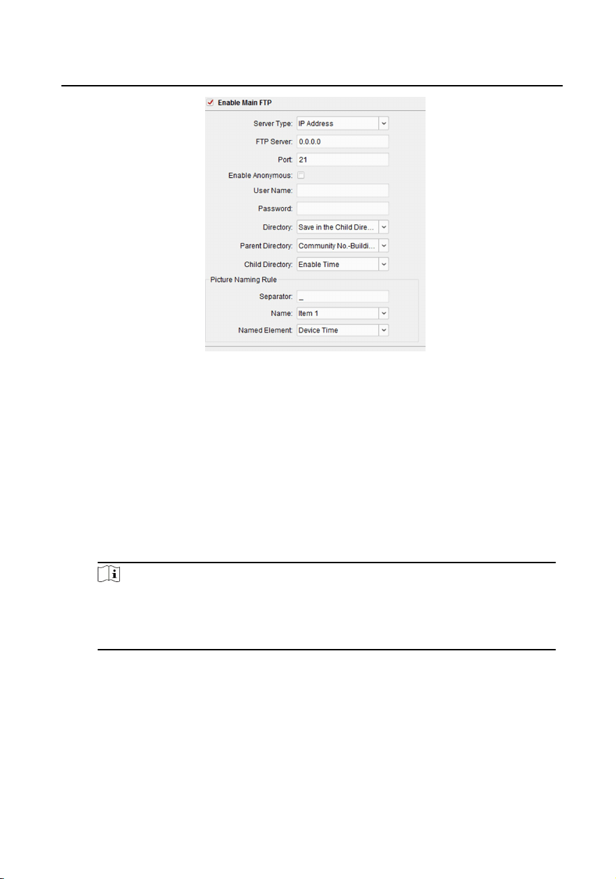
Figure 1-27 FTP Sengs
2.
Enable Enable Main FTP.
3. Select IP address from the drop-down list of server mode.
4.
Enter the FTP server address, and port No.
5.
Oponal: Enable the anonymity.
6.
Enter the name and password.
7.
Select the directory structure and set the separator, naming item, and naming
element.
8.
Click Save to enable the sengs.
Note
•
The default port No. is 21.
•
To enable anonymity or not is according to whether the FTP server enables
anonymity.
1.7.4 Advanced Sengs
Steps
1.
Click Advanced Sengs to enter the advanced network sengs page.
Module Door Staon Conguraon Guide
21
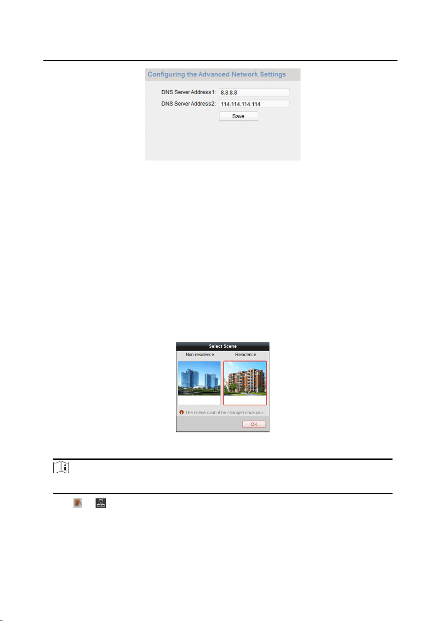
Figure 1-28 Advanced Sengs
2.
Enter the DNS server addresses.
3.
Click Save to enable the sengs.
1.8 Person and Card Management
You can add, edit, and delete the organizaon and person in Person and Card
Management module. Organizaon and person management is necessary for the
video intercom funcon.
For the rst me opening the Access Control module, the following dialog will pop
up and you are required to select the scene according to the actual needs. You can
select the scene as Non-residence and Residence.
Figure 1-29 Select Scene
Note
Once the scene is congured, you cannot change it later.
Click → to enter the Person and Card Management page.
Module Door Staon Conguraon Guide
22
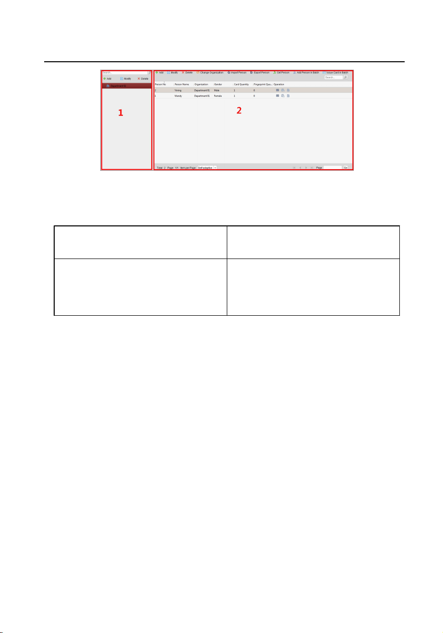
Figure 1-30 Person and Card Management
The page is divided into two parts: Organizaon Management and Person
Management.
Organizaon Management You can add, edit, or delete the
organizaon as desired.
Person Management Aer adding the organizaon, you can
add the person to the organizaon and
issue card to persons for further
management.
1.8.1 Organizaon Management
Add Organizaon
Steps
1.
In the organizaon list on the le, click Add to pop up the adding organizaon
page.
2.
Input the Organizaon Name as desired.
3.
Click OK to save the adding.
4.
You can add mulple levels of organizaons according to the actual needs.
1) You can add mulple levels of organizaons according to the actual needs.
2) Repeat Step 2 and Step 3 to add the sub organizaon.
3) Then the added organizaon will be the sub-organizaon of the upper-level
organizaon.
Module Door Staon Conguraon Guide
23
Note
Up to 10 levels of organizaons can be created.
Modify and Delete Organizaon
You can select the added organizaon and click Modify to modify its name.
You can select an organizaon, and click Delete buon to delete it.
Note
•
The lower-level organizaons will be deleted as well if you delete an
organizaon.
•
Make sure there is no person added under the organizaon, or the organizaon
cannot be deleted.
1.8.2 Person Management
Aer adding the organizaon, you can add person to the organizaon and manage
the added person such as issuing cards in batch, imporng and exporng person's
informaon in batch, etc.
Note
Up to 10,000 persons or cards can be added.
Add Person
Person informaon is necessary for the video intercom system. And when you set
linked device for the person, the intercom between intercom devices can be realized.
Steps
1.
Select an organizaon in the organizaon list and click Add on the Person panel
to pop up the adding person dialog.
Note
The Person No. will be generated automacally and is not editable.
2.
Set basic person informaon.
1) Enter basic informaon: person name, gender, phone No., birthday details,
and email address.
Module Door Staon Conguraon Guide
24
Note
The length of person name should be less than 15 characters.
2) Oponal: Click Upload Picture to select the person picture from the local PC
to upload it to the client.
Note
The picture should be in *.jpg format.
3) Oponal: You can also click Take Phone to take the person's photo with the
PC camera.
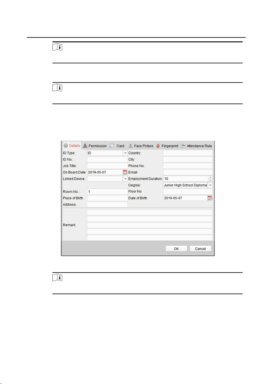
3.
Set linked device for the person.
1) Click Details.
Figure 1-31 Details
Note
Room No. can be congured from 1 to 9999.
2) Set the linked devices.
Linked Device
You can bind the indoor staon to the person.
Module Door Staon Conguraon Guide
25
Note
If you select Analog Indoor Staon in the Linked Device, the Door Staon
eld will display and you are required to select the door staon to
communicate with the analog indoor staon.
Room No.
You can enter the room No. of the person.
3) Click OK to save the sengs.
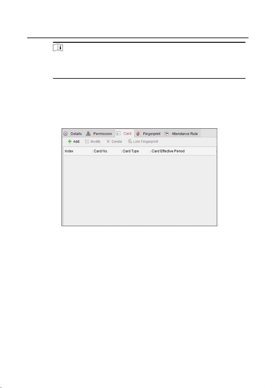
4.
Issue the card for the person.
1) Click Card.
Figure 1-32 Issue Card
2) Click Add to pop up the Add Card dialog.
Module Door Staon Conguraon Guide
26
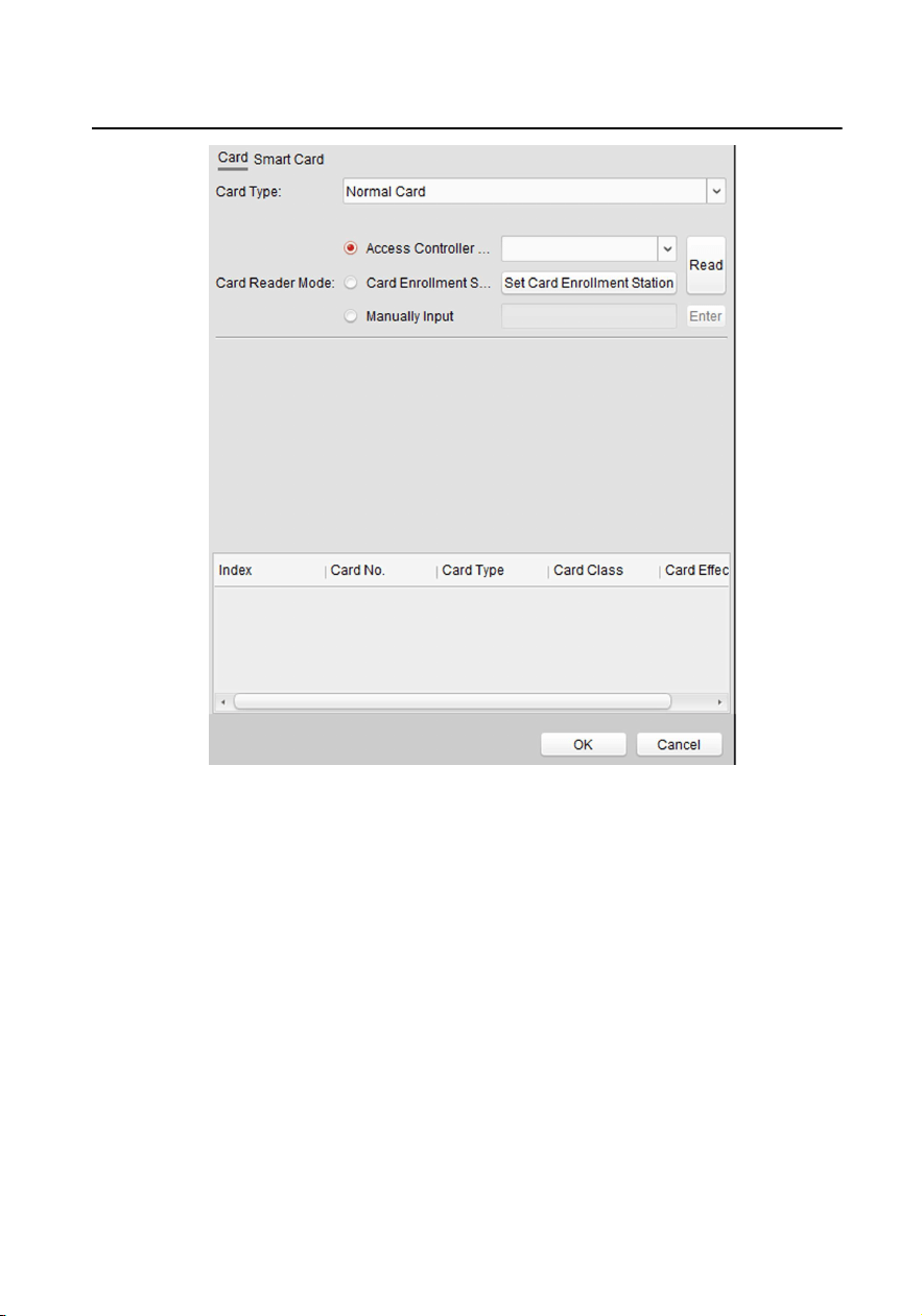
Figure 1-33 Add Card
3) Select Normal Card.
4) Enter the password of the card itself in the Card Password eld. The card
password should contain 4 to 8 digits.
5) Enter Card Number manually.
6) Click OK and the card(s) will be issued to the person.
Import and Export Person Informaon
The person informaon can be imported and exported in batch.
Steps
1.
Exporng Person: You can export the added persons' informaon in Excel format
to the local PC.
Module Door Staon Conguraon Guide
27
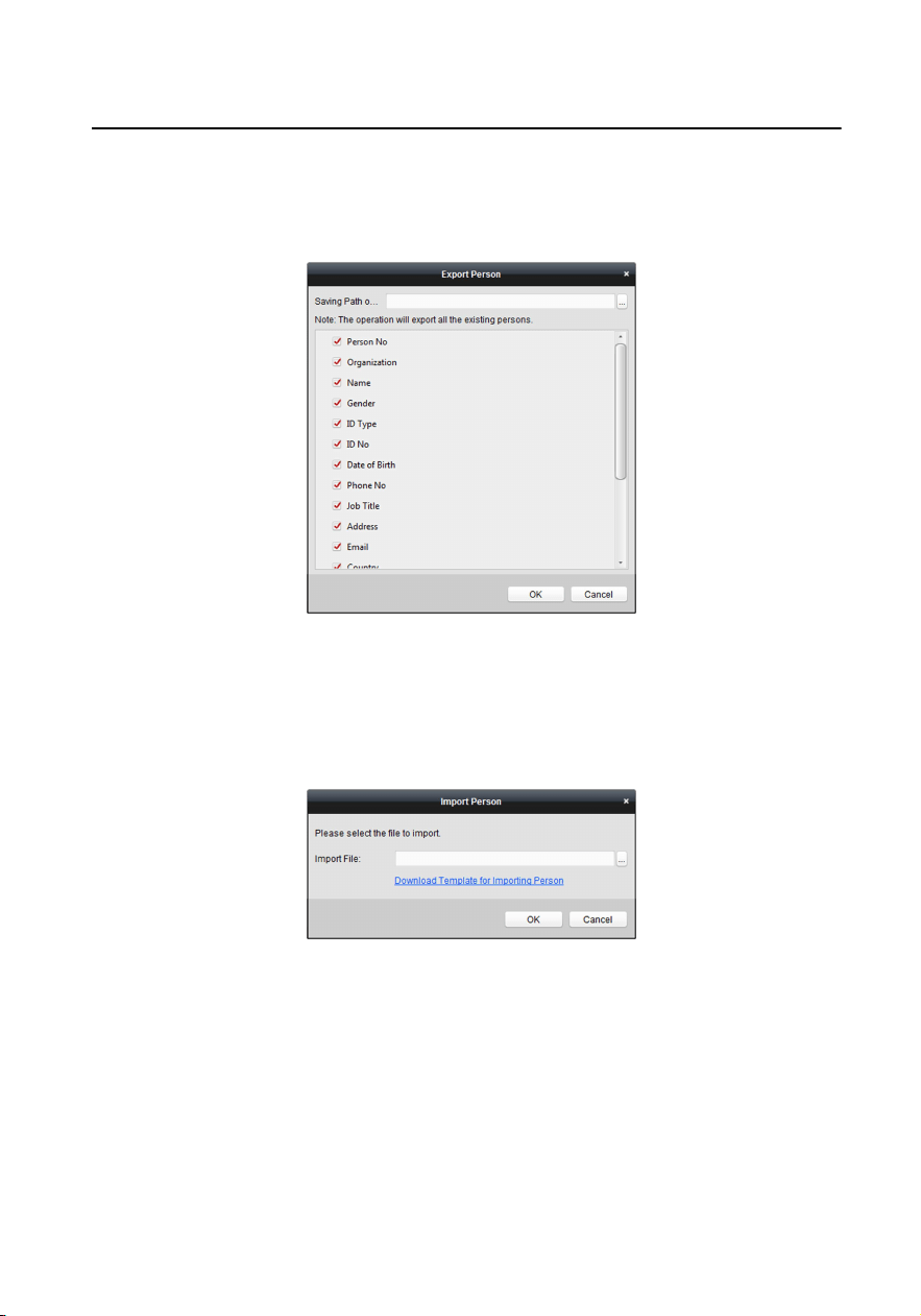
1) Aer adding the person, you can click Export Person to pop up the following
dialog.
2) Click ... to select the path of saving the exported Excel le.
3) Check the checkboxes to select the person informaon to export.
Figure 1-34 Export Person
4) Click OK to start exporng.
2.
Imporng Person: You can import the Excel le with persons informaon in
batch from the local PC.
1) Click Import Person.
Figure 1-35 Import Person
2) You can click Download Template for Imporng Person to download the
template rst.
3) Input the person informaon to the downloaded template.
4) Click ... to select the Excel le with person informaon.
5) Click OK to start imporng.
Module Door Staon Conguraon Guide
28
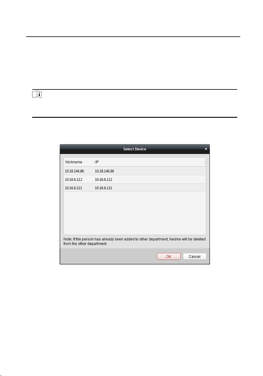
Get Person Informaon from Device
If the added device has been congured with person informaon (including person
details, ngerprint, issued card informaon), you can get the person informaon
from the device and import to the client for further operaon.
Steps
Note
This funcon is only supported by the device the connecon mothod of which is
TCP/IP when adding the device.
1.
In the organizaon list on the le, click to select an organizaon to import the
persons.
2.
Click Get Person to pop up the following dialog box.
Figure 1-36 Select Device
3.
The added access control device will be displayed.
4.
Click to select the device and then click OK to start geng the person
informaon from the device.
5.
Oponal: You can also double click the device name to start geng the person
informaon.
Module Door Staon Conguraon Guide
29
Note
•
The person informaon, including person details, person's ngerprint
informaon (if congured), and the linked card (if congured), will be
imported to the selected organizaon.
•
If the person name stored in the device is empty, the person name will be
lled with the issued card No. aer imporng to the client.
•
The gender of the persons will be Male by default.
Modify and Delete Person
To modify the person informaon and aendance rule, click
or in the
Operaon column, or select the person and click Modify to open the eding person
dialog.
You can click
to view the person's card swiping records.
To delete the person, select a person and click Delete to delete it.
Note
If a card is issued to the current person, the linkage will be invalid aer the person is
deleted.
Change Person to Other Organizaon
You can move the person to another organizaon if needed.
Steps
1.
Select the person in the list and click Change Organizaon.
2.
Select the organizaon to move the person to.
3.
Click OK to save the sengs.
Set Access Group to Assign Access Authorizaon to Persons
Aer adding the person and conguring the person's credenals, you can call
contacts via display module.
Module Door Staon Conguraon Guide
30

Steps
•
For one person, you can add up to 4 access groups to one access control point of
one device.
•
You can add up to 128 access groups in total.
•
When the access group sengs are changed, you need to apply the access
groups to the devices again to take eect. The access group changes include
changes of template, access group sengs, person's access group sengs, and
related person details (including card number, ngerprint, face picture, linkage
between card number and ngerprint, linkage between card number and
ngerprint, card password, card eecve period, etc).
1.
Click Access Control → Access Group to enter the Access Group interface.
2.
Click Add to open the Add window.
3.
In the Name text eld, create a name for the access group as you want.
4.
Select a template for the access group.
Note
You should congure the template before access group sengs. Refer to for
details.
5.
In the le list of the Select Person eld, select person(s) and the person(s) will be
added to the selected list .
6.
In the le list of the Select Door eld, select door(s) or door staon(s) for the
selected persons to access, and the selected door(s) or door staon(s) will be
added to the selected list.
7.
Click OK.
8.
Aer adding the access groups, you need to apply them to the access control
device to take eect.
1) Select the access group(s) to apply to the access control device.
To select mulple access groups, you can hold the Ctrl or Shi key and select
access groups.
2) Click Apply All to Devices to start applying all the selected access group(s) to
the access control device or door staon.
Module Door Staon Conguraon Guide
31

Cauon
•
Be careful to click Apply All to Devices, since this operaon will clear all
the access groups of the selected devices and then apply the new access
group, which may brings risk to the devices.
•
You can click Apply Changes to Devices to only apply the changed part of
the selected access group(s) to the device(s).
3) View the apply status in the Status column or click Applying Statusto view all
the applied access group(s).
The selected persons in the applied access groups will have the authorizaon to
enter/exit the selected doors/door staons with their linked card(s) or
ngerprints.
9.
Oponal: Click
to edit the access group if necessary.
Issue Card in Batch
You can issue mulple cards for the person with no card issued in batch.
Steps
1.
Click Issue Card in Batch to enter the dialog page. All the added person with no
card issued will display in the Person(s) with No Card Issued list.
Module Door Staon Conguraon Guide
32
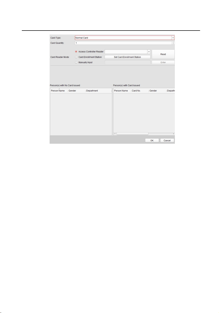
Figure 1-37 Issue Card in Batch
2. Select Normal Card as Card Type.
3.
Enter the card quanty issued for each person.
4.
Select the card reader mode and ll related informaon.
5.
Click Read/Enter.
6.
Aer issuing the card to the person, the person and card informaon will display
in the Person(s) with Card Issued list.
7.
Click OK.
1.9 Video Display
1.9.1 Video Parameters
Steps
1.
Click Video Parameters to enter the video parameters sengs page.
Module Door Staon Conguraon Guide
33
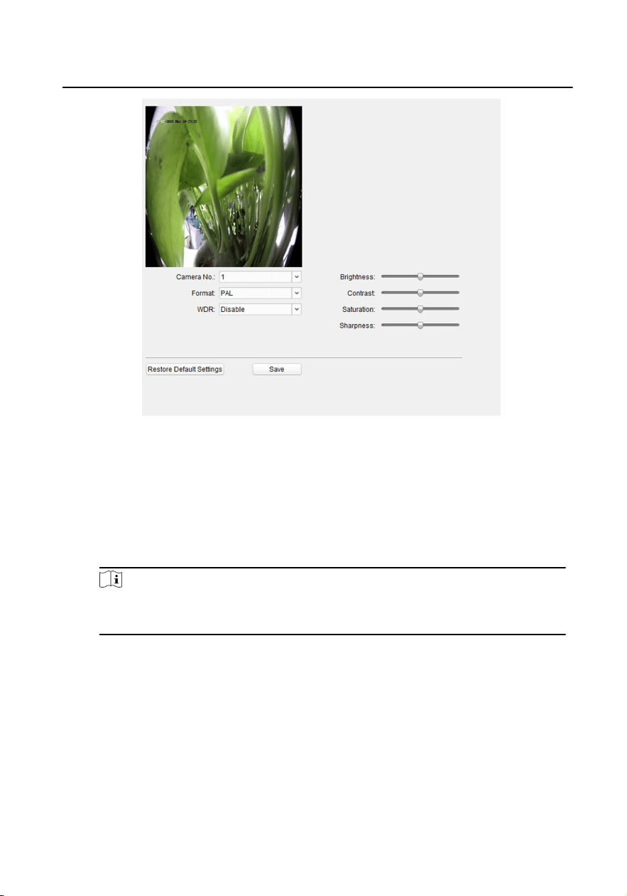
Figure 1-38 Video Parameters
2.
Select the Camera No.
3.
Select the video standard (PAL and NTSC can be selected).
4.
Oponal: Enable WDR mode.
5.
Set the Brightness, Contrast, Saturaon and Sharpness of the video.
6.
Click Save.
Note
Click Restore Default Sengs to restore all video parameters excluding network
parameters to the factory sengs.
1.9.2 Video & Audio
Steps
1.
Click Video & Audio to enter the video parameters sengs page.
Module Door Staon Conguraon Guide
34
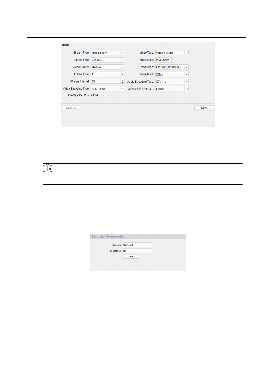
Figure 1-39 Video & Audio
2.
Set the parameters.
3.
Click Save.
Note
It's suggested to keep the default sengs to ensure the video/image quality.
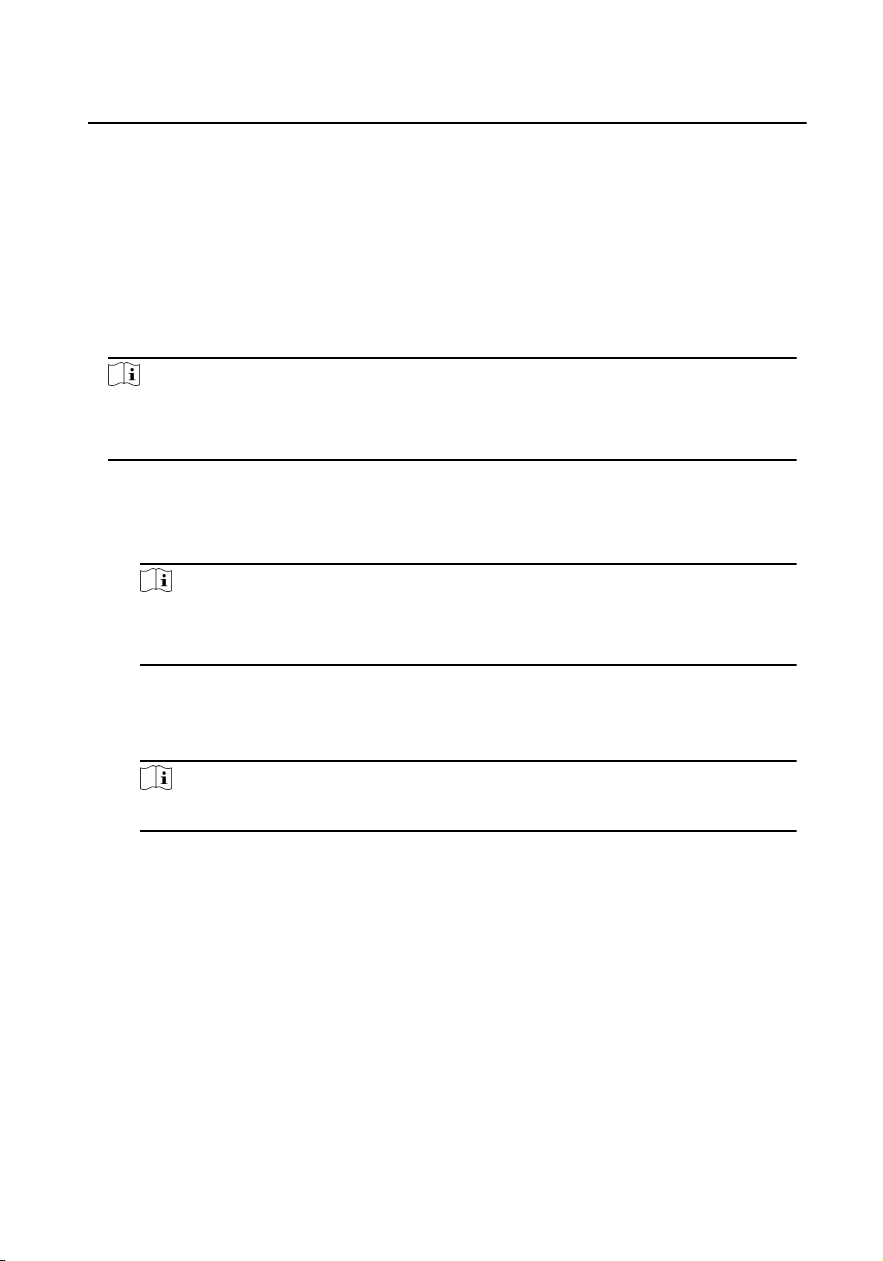
1.10 BLC Mode
Steps
1.
Click Back Light Compensaon to enter the sengs page.
Figure 1-40 BLC Mode
2.
Set the BLC Mode.
3.
Click Save.
Module Door Staon Conguraon Guide
35
2 Video Intercom Operaon
2.1 Video Intercom Operaon via Device
2.1.1 Call Resident
Note
•
Make sure you have congured the room No. of the device.
•
Make sure you have add contacts to the device via iVMS-4200 Client Soware.
You can call corresponding resident in three ways:
•
Press the call buon on the main unit or on the nametag unit.
•
Enter the Room No. on the keypad module, and press # to start calling.
Note
-
You can press * via keypad module to hang up.
-
You can press Back buon via display module to hang up.
•
Press ˄ or ˅ on the display module to enter the contact list.
Press or hold ˄/˅ to select a contact.
Press OK and conrm to call.
Note
Hold ˄ or ˅ to scroll the page up or down faster.
2.1.2 Issue Card
Before You Start
Make sure you have issue the card locally or remotely. See Person Management for
issuing card via Client soware for details.
Issue Card via Main Card: You can swipe card to issue it aer swiping the main card
in advance.
Steps
1.
Swipe the main card on the card reading area, and hear two beeps.
2.
Swipe the unauthorized sub cards in turn aer hearing a beep.
Module Door Staon Conguraon Guide
36
3. Swipe the main card again to end the card issuing process.
Note
•
DS-KD-M supports Mifare card, DS-KD-E supports EM card.
•
If the amount of sub cards exceeds 10000, no more sub cards can be issued.
•
Up to 5 sub cards can be issued once. The issued frequency is no more than
2000.
2.1.3 Unlock Door
Unlock Door by Password
You can unlock the door by inpung the password via the keypad module.
Three formats of password are supported. They are:
•
【#】+ Public Password +【#】
•
【#】+ Password +【#】
•
【#】+ Duress Password +【#】
Note
•
Password contains 6 digits.
•
You're allowed to set 3 public passwords via iVMS-4200 client soware.
•
The password varies according to dierent rooms.
Unlock Door by Card
Note
Make sure the card has been issued. You can issue the card via the door
staon, or via iVMS-4200 client soware.
Swipe the card on the card inducon area to unlock the door.
Note
The main card does not support unlocking the door.
Module Door Staon Conguraon Guide
37
2.2 Video Intercom Operaon via Client Soware
The Video Intercom Management module provides the funcon of video intercom,
checking call logs and managing noce via the iVMS-4200 Client Soware.
Note
For the user with access control module permissions, the user can enter the Access
Control module and manage video intercom and search informaon.
You should add the device to the soware and congure the person to link the
device in Access Control module before your conguraon remotely.
Click
→ on the le icon bar to enter the Video Intercom page.
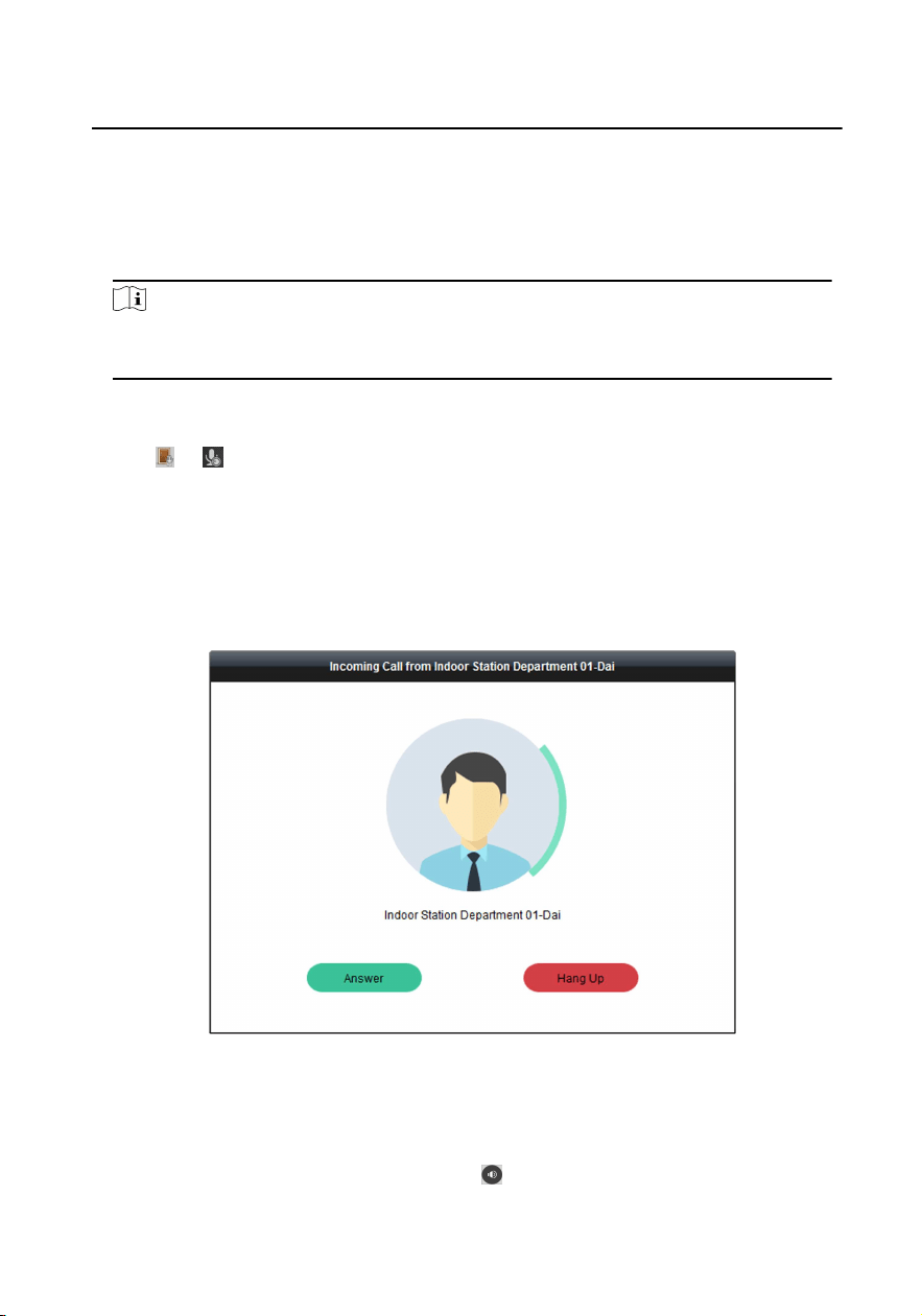
2.2.1 Receive Call from Door Staon
Steps
1.
Select the client soware in door staon page to start calling the client and an
incoming call dialog will pop up in the client soware.
Figure 2-1 Device Call
2.
Click Answer to answer the call. Or click Hang Up to decline the call.
3.
Aer you answer the call, you will enter the In Call page.
Adjust the Volume of
Loudspeaker
Click
to adjust the volume of loudspeaker.
Module Door Staon Conguraon Guide
38
Hang Up
Click
to hang up.
Adjust the Volume of
Microphone
Click
to adjust the volume of the
microphone.
Unlock Remotely
For door staon, you can click
to open the
door remotely.
Note
•
One video intercom device can only connect with one client soware.
•
The maximum ring duraon can be set from 15s to 60s via the Remote
Conguraon of the video intercom device.
•
The maximum speaking duraon between indoor staon and iVMS-4200 can
be set from 120s to 600s via the Remote Conguraon of indoor staon.
•
The maximum speaking duraon between door staon and iVMS-4200 can
be set from 90s to 120s via the Remote Conguraon of door staon.
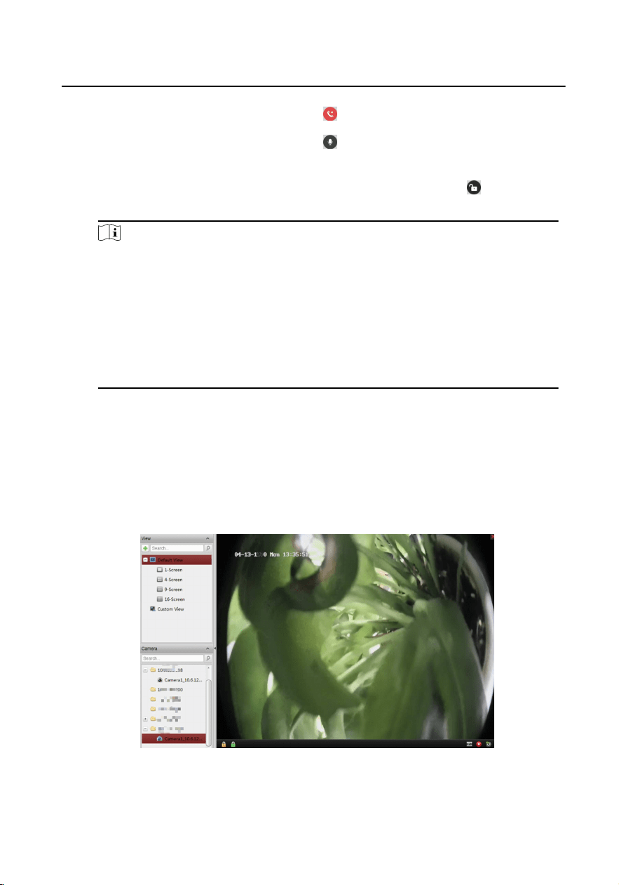
2.2.2 Live View via Door Staon
You can get the live view of the main unit in the Main View module and control the
door staon remotely.
In the Main View module, double-click a door staon or drag the device to a display
window to start the live view.
Figure 2-2 Live View
Right click on the live view page, clickthe unlock iconto remote unlock the door.
Module Door Staon Conguraon Guide
39
2.2.3 View Call Logs
Before You Start
You can check all the call logs, including dialed call logs, received call logs and missed
call logs. You can also directly dial via the log list and clear the logs.
Steps
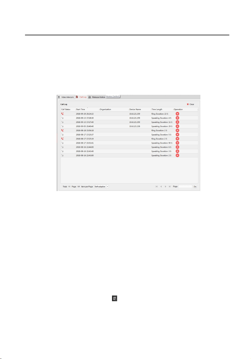
1.
In the Video Intercom page, click Call Log to enter the Call Log page.
Figure 2-3 View Call Logs
All the call logs will display on this page and you can check the log informaon,
e.g., call status, start me, resident's organizaon and name, device name and
ring or speaking duraon.
2.
Oponal: Click the call buon to re-dial the resident.
3.
Oponal: Click the cancel buon to delete the call log. Or you can click Clear to
delete all logs.
2.2.4 Search Video Intercom Informaon
You can search the call logs between the iVMS-4200 client soware and video
intercom devices, device unlocking logs and the sent noce informaon.
In the Access Control module, click
to open the Search page
Search Call Logs
Module Door Staon Conguraon Guide
40
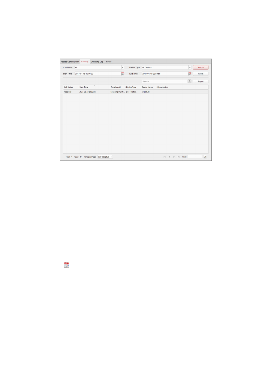
Steps
1. In the Informaon Search page, click Call Log to enter the Call Log page.
Figure 2-4 Call Logs
2.
Set the search condions, including call status, device type, start me and end
me.
Call Status
Click ˅to unfold the drop-down list and select the call status as Dialed,
Received or Missed. Or select All to search logs with all statuses.
Device Type
Click ˅ to unfold the drop-down list and select the device type as Indoor
Staon, Door Staon, Outer Door Staon or Analog Indoor Staon. Or
select All Devices to search logs with all device types.
Start Time/End Time
Click
to specify the start me and end me of a me period to search the
logs.
Reset the Sengs Click Reset to reset all the congured search
condions.
3.
Click Search and all the matched call logs will display on this page.
4.
Oponal: Check the detailed informaon of searched call logs, such as call
status, ring/speaking duraon, device name, resident organizaon, etc.
5.
Oponal: Input keywords in the Search eld to lter the desired log.
6.
Oponal: Click Export to export the call logs to your PC.
Module Door Staon Conguraon Guide
41
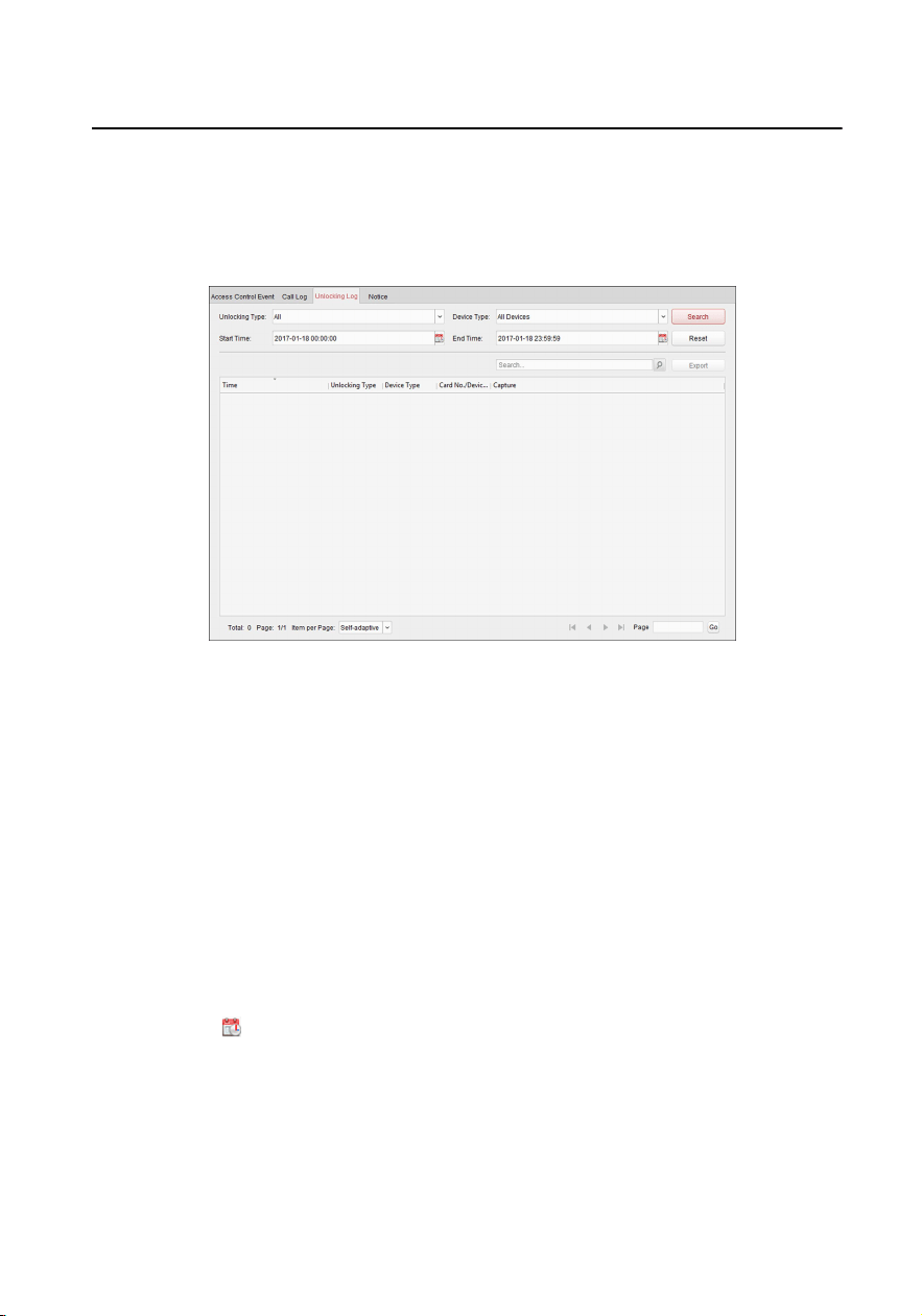
Search Unlocking Logs
Steps
1.
In the Informaon Search page, click Unlocking Log to enter the Unlocking Log
page.
Figure 2-5 Unlocking Logs
2.
Set the search condions, including unlocking type, device type, start me and
end me.
Unlocking Type
Click ˅ to unfold the drop-down list and select the unlocking type as Unlock
by Password, Unlock by Duress, Unlock by Card, Unlock by Resident or
Unlock by Center. Or select All to search logs with all unlocking types.
Device Type
Click ˅ to unfold the drop-down list and select the device type as Door
Staon or Door Staon (V Series). Or select All Devices to search logs with
all device types.
Start Time/End Time
Click
to specify the start me and end me of a me period to search the
logs.
`Reset the Sengs Click Reset` to reset all the congured search
condions.
3.
Click Search and all the matched unlocking logs will display on the page.
Module Door Staon Conguraon Guide
42

4. Oponal: Check the detailed informaon of searched unlocking logs, such as
unlocked me, card No., device No., etc.
5.
Oponal: Input keywords in the Search eld to lter the searching result.
6.
Oponal: Click
on the Capture column to view the captured pictures.
Note
Viewing captured picture should be supported by device.
7.
Oponal: Click Export to export the unlocking logs to your PC.
Module Door Staon Conguraon Guide
43

UD14533B