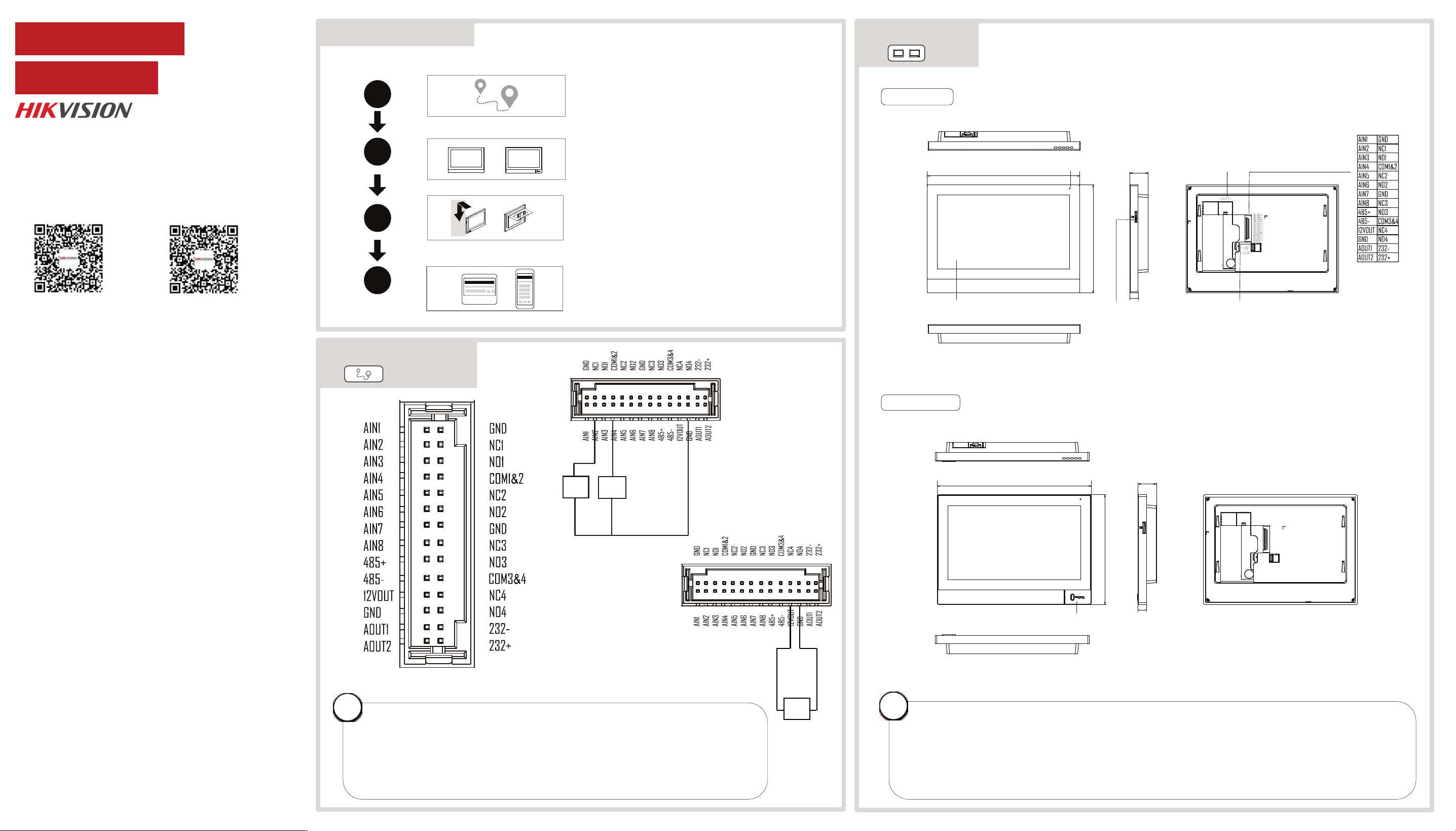
Alarm Input Terminal
Alarm
Input
Device
Detector
- +
Plastic Model
Metal Model
Alarm
Input
Device
178.4 mm
126.4 mm
21.8 mm
180.4 mm
128.4 mm
21.8 mm
TF CardSlot
Unlock Button
Screen
Microphone
•Different models may have different ports, please refer to the specific device.
•Some models don’t have unlock button, please refer to the specific device.
•Only some models support Wi-Fi, please refer to the actual product.
•If a power adapter is provided in the device package, use the provided adapter only. If no
power adapter is provided, ensure the power adapter or other power supply complies with
Limited Power Source. Refer to the product label for the power supply output parameters.
i
Alarm Interface
1
2
4
Appearance
Installation
Activation and Quick Configuration
Quick Flow Chart
2
Appearance
1
Wiring and Terminal
•Do not wire the device to the 220V electric supply directly.
•The indoor station supports 12V DC power supply or private PoE power supply. After
connecting to private PoE cable, there is no need to connect other power cord. If the
cable connected is not private PoE cable, you need to connect power cord to the device
for power supply.
•The device only supports connecting to detector when powered by private PoE cable.
The device supports 12V, 200mA (maximum 500mA) power supply for the detector.
i
Wiring and Terminal
3
LAN (POE)
Power Interface
(GND 12VDC)
10 mm
10 mm
Scan the QR code above to get User
Manual of Door Station.
Scan the QR code above to get User
Manual of Indoor Station.
DS-KH8380-WTE1
UD43390BVideo Intercom Kit
DS-KIS613-S
Network Indoor Station
If a power adapter is provided in the device package, use the provided adapter only. If no
power adapter is provided, ensure the power adapter or other power supply complies with
Limited Power Source. Refer to the product label for the power supply output parameters.
Если адаптер питания входит в комплект поставки устройства, используйте только
прилагаемый адаптер. Если адаптер питания не входит в комплект поставки, убедитесь,
что используемый вами адаптер питания или источник питания соответствует
требованиям к ограничению мощности. Выходные параметры источника питания
указаны на его паспортной табличке.
Amennyiben a készülék csomagja tartalmaz hálózati adaptert, kizárólag a mellékelt adaptert
használja. Ha a csomag nem tartalmaz hálózati adaptert, bizonyosodjon meg, hogy a használt
hálózati adapter vagy más tápegységek megfelelnek a korlátozott áramforrásokra vonatkozó
előírásoknak. A tápegység teljesítményének paraméterei a termék címkéjén találhatók.
Wenn im Lieferumfang des Geräts ein Netzteil enthalten ist, verwenden Sie nur das
mitgelieferte Netzteil. Wenn kein Netzteil mitgeliefert wird, stellen Sie sicher, dass das Netzteil
oder eine andere Stromversorgung den Anforderungen an eine Stromquelle mit begrenzter
Leistung entspricht. Die Ausgangsparameter des Netzteils sind auf dem Produktaufkleber
angegeben.
Utilizzare solo l'alimentatore in dotazione, se incluso nella confezione del dispositivo. Se
l'alimentatore non è incluso, accertarsi di utilizzare un modello conforme allo standard sulle
fonti di alimentazione limitate. Consultare l'etichetta del prodotto per i parametri dell'uscita di
alimentazione.
Pokud je v balení zařízení dodán napájecí adaptér, používejte pouze dodaný adaptér. Pokud
není napájecí adaptér dodán, zajistěte, aby napájecí adaptér nebo jiný napájecí zdroj
vyhovovaly požadavkům na omezený zdroj napájení. Parametry výstupu napájení viz štítek
výrobku.
Ak bolo zariadenie dodané s napájacím adaptérom, použite iba dodaný adaptér. Ak napájací
adaptér nie je dodaný, uistite sa, že napájací adaptér alebo iný zdroj napájania vyhovuje
obmedzenému zdroju napájania. Parametre výstupu napájacieho zdroja nájdete na štítku
produktu.
Si un adaptateur secteur est fourni dans l’emballage de l’appareil, n’utilisez que l’adaptateur
fourni. Si aucun adaptateur secteur n’est fourni, assurez-vous que l’adaptateur secteur ou
toute autre source d’alimentation est conforme à la source d’alimentation limitée. Reportez-
vous à l’étiquette du produit pour connaître les paramètres de sortie de l’alimentation.
Jeżeli w pakiecie z urządzeniem dostarczany jest zasilacz, należy używać wyłącznie tego
zasilacza. Jeżeli zasilacz nie jest dostarczany w pakiecie z urządzeniem, należy używać zasilacza
zgodnego z wymaganiami dotyczącymi źródeł zasilania z własnym ograniczeniem (LPS, Limited
Power Source). Informacje dotyczące wymaganego zasilania podano na etykiecie produktu.
Als een voedingsadapter in de verpakking van het apparaat is geleverd, mag u alleen deze
adapter gebruiken. Als er geen voedingsadapter is meegeleverd, moet u ervoor zorgen dat de
voedingsadapter of een andere stroombron voldoet aan de Beperkte voedingsbron. Raadpleeg
het productlabel voor de parameters voor de stroomuitvoer.
Se a embalagem do dispositivo incluir um adaptador de alimentação, utilize apenas o
adaptador fornecido. Se não for fornecido um adaptador, certifique-se de que o adaptador de
alimentação ou qualquer outra fonte de alimentação está em conformidade com a Fonte de
Alimentação Limitada. Consulte a etiqueta do produto para obter os parâmetros nominais da
fonte de alimentação.
Si el paquete del dispositivo incluye un adaptador de corriente, utilice únicamente el
adaptador suministrado. Si no se suministra un adaptador de corriente, asegúrese de que el
adaptador de corriente u otra fuente de alimentación que utilice cumple con el límite de la
fuente de alimentación. Consulte la etiqueta del producto para conocer los parámetros de
salida de la fuente de alimentación.
Dacă dispozitivul se furnizează cu un adaptor de alimentare, utilizaţi-l numai pe acesta. Dacă
nu se furnizează niciun adaptor de alimentare, asiguraţi-vă că adaptorul sau o altă alimentare
electrică este compatibilă cu sursa de alimentare limitată. Pentru parametrii de ieşire ai
alimentării electrice, consultaţi eticheta produsului.
Hvis en strømadapter følger med i enhedens pakke, må du kun bruge den medfølgende
adapter. Hvis der ikke medfølger en strømadapter, skal du sikre, at strømadapteren eller en
anden strømforsyning overholder LPS (Limited Power Source). Find strømforsyningens
udgangsparametre i produktets mærkat.
Cihaz paketinde bir güç adaptörü varsa, sadece verilen adaptörü kullanın. Güç adaptörü
verilmediyse, güç adaptörünün veya diğer güç kaynağının Sınırlı Güç Kaynağı ile uyumlu
olduğundan emin olun. Güç kaynağı çıkış parametreleri için ürün etiketine bakın.
Якщо блок живлення входить у комплект поставки, використовуйте тільки наданий блок
живлення. Якщо блок живлення не входить у комплект поставки, переконайтеся, що блок
живлення або інше джерело живлення відповідає вимогам до джерел живлення
обмеженої потужності. Вимоги до вихідних параметрів джерела живлення див. на
етикетці виробу.
Jika adaptor daya disediakan dalam kemasan perangkat, hanya gunakan adaptor yang
disediakan. Jika adaptor daya tidak disediakan, pastikan adaptor daya atau catu daya lain
sesuai dengan Sumber Daya Terbatas. Lihat label produk untuk parameter output catu daya.
ကိရိယာ ထုပ္ပိုးမႈတြင္ ပါဝါ အဒက္ပတာ ထည့္သြင္းပါရွိပါက၊ ေပးထားေသာ အဒက္ပတာကိုသာ
အသံုးျပဳပါ။ ပါဝါ အဒက္ပတာ ပါရွိျခင္းမရွိပါက၊ ပါဝါရင္းျမစ္ ကန္႔သတ္မႈႏွင့္ ကိုက္ညီေသာ ပါဝါ
အဒက္ပတာ သို႔မဟုတ္ အျခား ပါဝါ ေပးသြင္းမႈမ်ားကို သံုးရန္ ဂရုျပဳပါ။ ပါဝါေပးသြင္းမႈ အထြက္
ကန္႔သတ္ခ်က္မ်ားအတြက္ ထုတ္ကုန္တြင္ ေရးသားထားခ်က္ကို ကိုးကားပါ။
2
Appearance
148
14
83.5
60
3.1
89.7
83.5
2.5
55
54
159.5
102
171.1
120
102
60
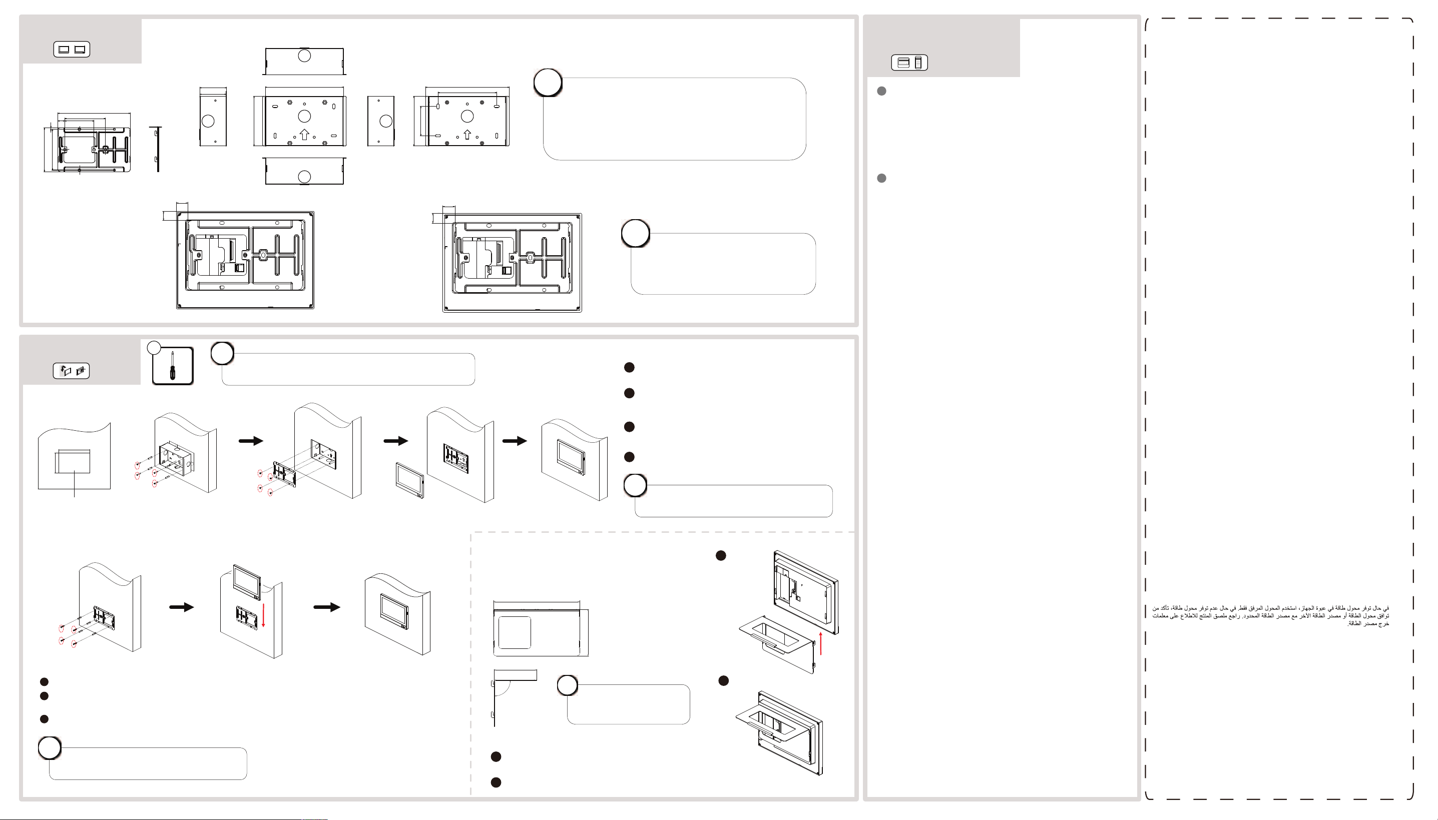
•The mounting plate is fixed to the installation frame.
•The suggested installation hole size should be less
than 80mm × 80mm.
•During construction or renovation, remember to
protect the mounting plate and junction box.
i
Before drilling holes on the wall,
please take the instruction
pictures on the left and the size
the device into consideration.
i
Installation Frame
Mounting Plate
Plastic Model Metal Model
15.2
12
16.2
13
Unit:mm
3
Installation
Fix the installation frame to the wall using 4 pieces
KA4X25 screws and wall plugs.
Align the installation holes of the mounting plate with
the positions of holes of the installation frame. Use 4
pieces of SC-KM4X6 screws to fix the mounting plate to
the wall.
Make sure the cables are connected properly. Align the
mounting holes on the back of the device with the
mounting plate, and hang the device onto the plate
from top to bottom.
Finished.
1
2
3
+
When performing construction or renovation, it
is necessary to protect the indoor unit base.
i
54.5
160.5
103
Flush Mounting
Use 4 KA4X25 screws with expansion anchors to mount the mounting plate to the wall.
Make sure the cables are connected properly. Align the mounting holes on the back of the device with the
mounting plate, and hang the device onto the plate from top to bottom.
Finished.
1
2
3
When performing construction or renovation, it
is necessary to protect the indoor unit base.
i
Surface Mounting
4
Suggested Depth
148
80
73.1
90°
Table Bracket
Mounting with Table Bracket
1
2
Make sure the cables are connected properly.
Align the bracket with the mounting holes on the
back of the device, and push the bracket onto the
device from bottom to top.
Finished.
The size of the table
bracket is the same for
metal and plastic model.
i
The mounting methods and procedures are the same for metal
and plastic model. Here uses the metal model as an example.
i
4
Activation and
Quick Configuration
Activate Indoor Station
1. Power on the device. It will enter the activation page
automatically.
2. Create a password and conrm it.
3. Tap OK to activate the indoor station.
You are required to activate the device rst by setting a strong
password before you can use the device.
1
1. Choose Language and tap Next.
2. Set password reset method and tap Next.
- Enter the Reserved Email address, then you can reset the
password by email.
Note: On the security questions settings page, you can tap
Change to Reserved Email to modify the password reset method.
- Tap Change to Security Question. Select 3 security questions
from Deficiency List and enter the answers of the questions, then
you can reset the password by answering security questions.
3. Set network parameters and tap Next.
- Edit Local IP, Subnet Mask and Gateway parameters.
- Enable DHCP, the device will get network parameters
automatically.
4. Congure the indoor station and tap Next.
a. Select Indoor Station Type.
b. Edit Floor and Room No.
c. Set the Registration Password.
5. (Optional) Slide to enable the mobile client service. Tap Next.
6. Linked related devices and tap Next. If the device and the
indoor station are in the
same LAN, the device will be displayed in the list. Tap the device or
enter the serial No.
to link.
a. Tap the door station in the list to link.
b. Tap the settings icon to pop up the Network Settings page.
c. Edit the network parameters of the door station manually or
enable DHCP to get
the network parameters automatically.
d. Tap OK to save the settings.
7. Tap Finish to save the settings.
Quick Conguration
2
1
2
DS-KV61X4 Series
Video Intercom Villa Door Sta�on
Terminal and Wiring
2
Installa�on Accessory
3
ENGLISH
Diagram References
1
Appearance
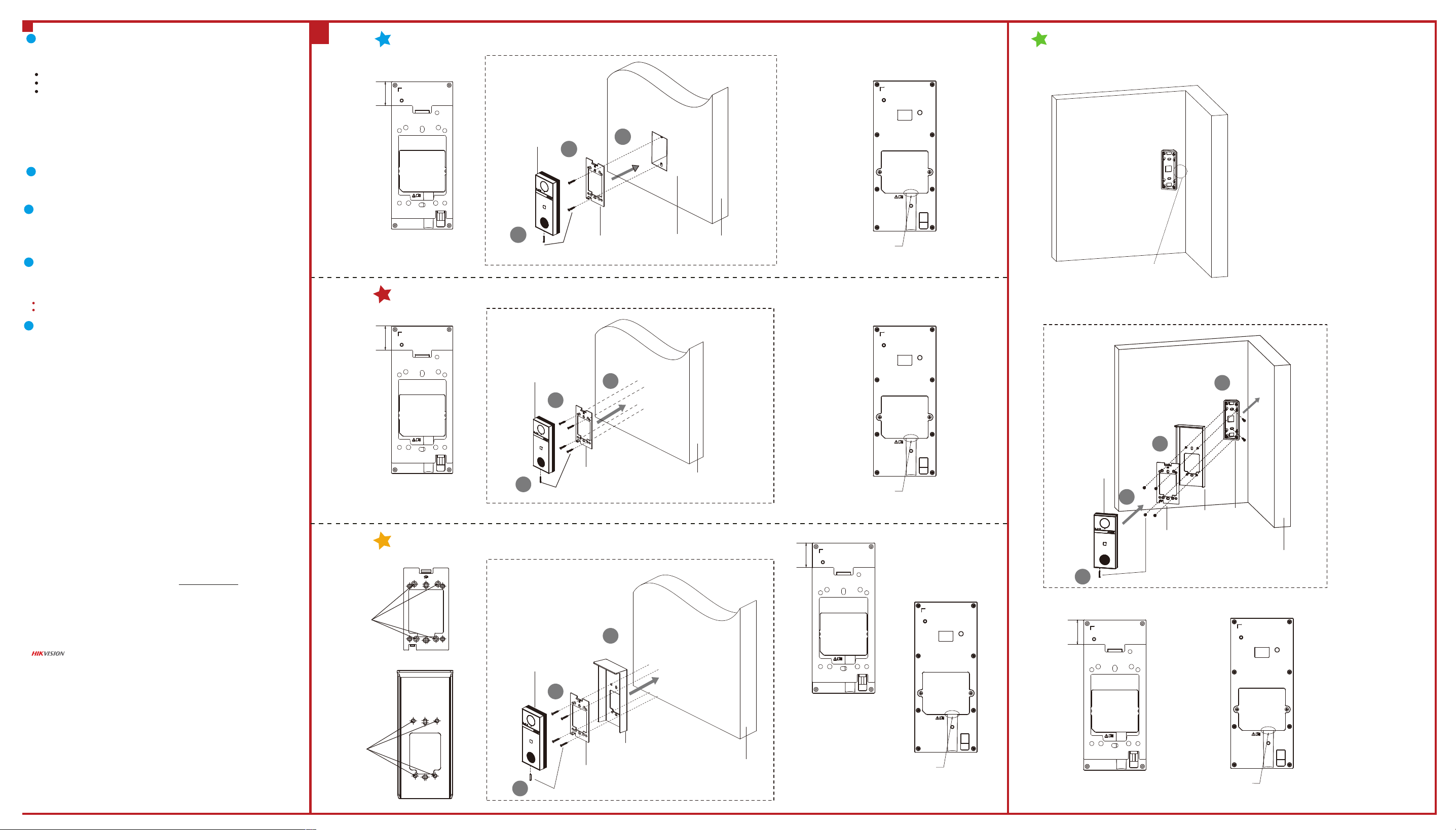
Moun�ng with Gang Box
1. Align the mounting holes of the plate with the holes of the gang box, then secure the
mounting plate to the wall using 2PCS SC-KA4X25 screws.
2. Connect all cables and secure the rear interface cover, then mount the device onto the
plate from top to bottom.
3. Fix the device on the moun�ng plate with 1PCS SC-M3X18-T10-SUS-NL screw.
Make sure all related equipments are power-o during the installa�on.
Tools that you need to prepare for installa�on: Drill and gradienter.
Before You Start
1. Fix the mounting plate to the wall using 4PCS SC-KA4X25 screws.
2. Connect all cables and secure the rear interface cover, then mount the device onto the
plate from top to bottom.
3. Fix the device on the moun�ng plate with 1PCS SC-M3X18-T10-SUS-NL screw.
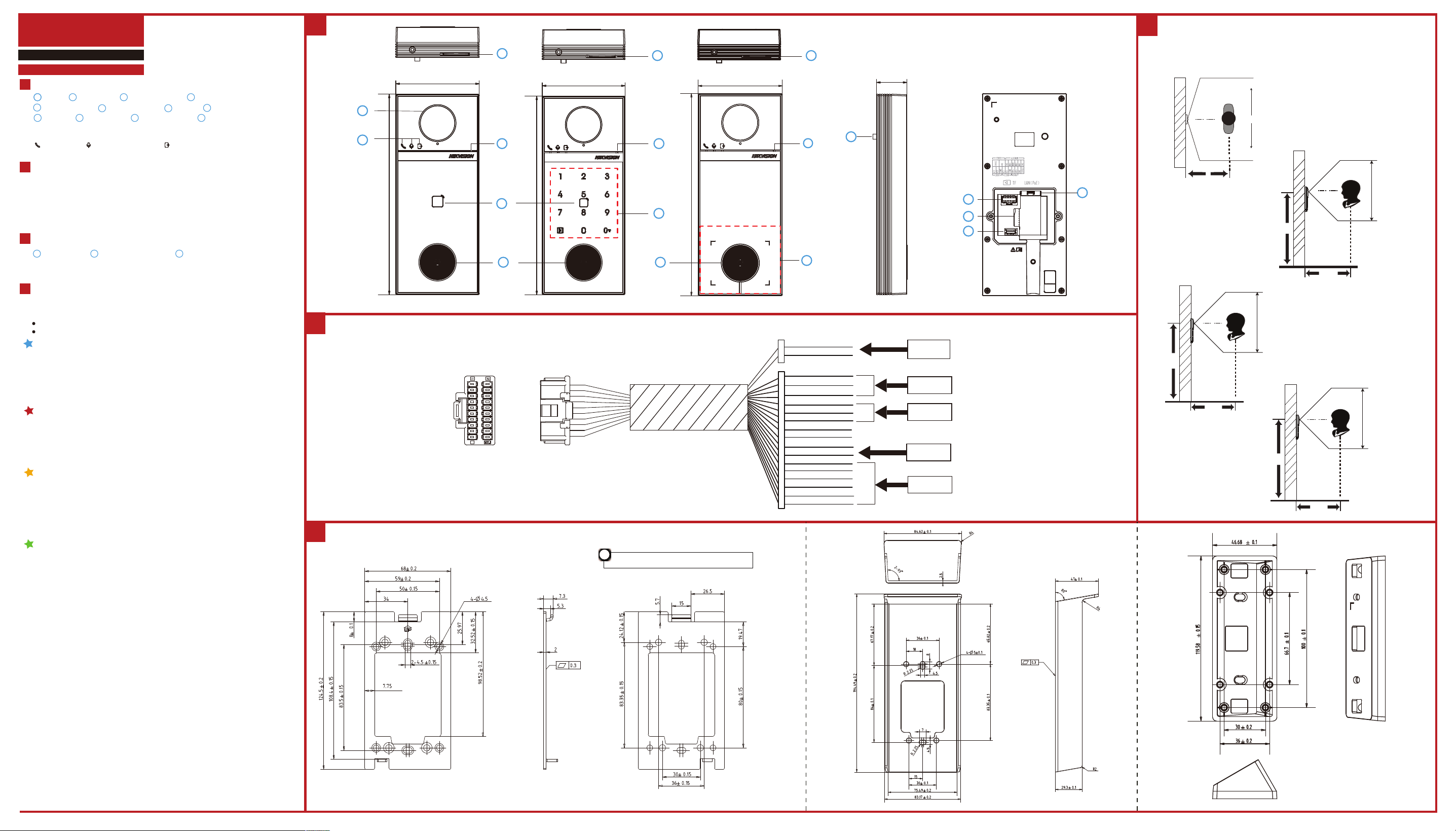
NC1 : Door Lock 1 Relay Output (NC1)
NO1 : Door Lock 1 Relay Output (NO1)
NC2 : Door Lock 2 Relay Output (NC2)
NO2 : Door Lock 2 Relay Output (NO2)
COM1&COM2: Common Interface
485-: RS-485 Interface
485+: RS-485 Interface
12 VDC IN: Power Supply Input
GND: Grounding
AIN1-AIN4: Analog Input (For Alarm in)
1
Moun�ng Plate
Note: The dimension of the moun�ng plate is 124.5 mm × 68 mm × 7.3 mm.
The dimension of the rain shield is 194.49 mm × 84.62 mm × 47 mm.
The dimension of the mounting bracket is 119.58 mm × 46.68 mm × 28.39 mm.
Installa�on
4
Note: The intallation methods for KV6114 and KV6124 are the same. Here takes KV6114 as an example.
2
Surface Moun�ng without Rain Shield
Note: Apply silicone sealant among the cable wiring area to keep the raindrop from entering. Please refer
to figure A.
Note: Apply silicone sealant among the cable wiring area to keep the raindrop from entering. Please refer
to figure B.
Note: Please refer to the picture aside for details.
Note: KV6114 and KV6124 have exactly the same port markings and size on the back panel.
Indicator Descrip�on
Call: Orange Communicate: White Unlock: Green
Camera
2
Physical Button
3
4
Card Reading Area
5
12 Touch Buttons
6
TAMPER
7
Speaker
8
1
Indicators
Microphone
Terminals
9
Debugging Port
11
Network Interface
12
TF Card Slot
10
3
1
69 mm
24.7 mm
164 mm
69 mm
164 mm
1
2
5
3
4
6
7
8
9
11
12
10
69 mm
164 mm
3
8
8
5
4
4
Yellow NC1
Green NO1
Blue COM1
White NC2
Purple NO2
Brown COM2
12 VDCRed
GND
Green AIN1
Yellow AIN2
Orange AIN3
Blue AIN4
Black GND
Black GND
Black
Yellow RS-485+
Blue RS-485-
Power Input
RS485
Alarm In
Lock 1
Lock 2
12 VOUTRed
GNDBlack
i
Install with this side facing outward.
+0.2
-0.1
Front
Back
2
Rain Shield (Optional)
1. Fix the mounting plate and rain shield to the wall using 4PCS SC-KA4X25 screws.
2. Connect all cables and secure the rear interface cover, then mount the device onto the
plate from top to bottom.
3. Fix the device on the moun�ng plate with 1PCS SC-M3X18-T10-SUS-NL screw.
Surface Moun�ng with Rain Shield (Optional)
4
Recommended Installation Height (The distance between the camera
and the ground): 1.4 m to 1.6 m.
Note:
•Apply silicone sealant among the cable wiring area to keep the raindrop from entering. Please refer to figure C.
•The package does not include a rain shield, which needs to be purchased separately.
3
Mounting Bracket (Optional)
Unit: mm
Horizontal: 150°
0.5 m
Vertical: 77°
Highest Height: 1.78 m
Lowest Height: 1.02 m
0.5 m
1.4 m
Vertical: 77°
Highest Height: 1.88 m
Lowest Height: 1.12 m
0.5 m
1.5 m
Vertical: 77°
Highest Height: 1.98 m
Lowest Height: 1.22 m
0.5 m
1.6 m
1. Fix the mounting bracket to the wall using 2PCS SC-KA4X25 screws.
2. Fix the mounting plate and rain shield to the wall using 4PCS SC-KM4X8-SUS-GB819 screws.
3. Connect all cables and secure the rear interface cover, then mount the device onto the plate
from top to bottom.
4. Fix the device on the moun�ng plate with 1PCS SC-M3X18-T10-SUS-NL screw.
Surface Moun�ng with Rain Shield and Mounting Bracket (Optional)
Note:
•Apply silicone sealant among the cable wiring area to keep the raindrop from entering. Please refer to figure D.
The package does not include rain shield and mounting bracket. You need to purchase them separately.
•When installing a mounting bracket, the distance between the short side of the bracket and the wall should be
greater than 20mm.
•If you want to intall a mouting bracket without a rain shield, the general installation procedure are similar as
above. You just need to omit the rain cover installation part. What’s more, the screws used in step 2 will be
changed to 4PCS SC-KM4X5-SUS-GB819 screws.
2
1
3
Screws
Villa Door Station
Mounting Plate
Gang Box
Wall
1
3
2
Screws
Villa Door Station
Mounting Plate
Wall
Surface Moun�ng without Rain Shield
B
Installation Position
A
26.7 mm
Appl y
Sili cone
Seal a nt
Appl y
Sili cone
Seal a nt
Installation Position
26.7 mm
4
About this Document
● This Document includes instruc�ons for using and managing the Product. Pictures, charts, images and all other informa�on
hereina�er are for descrip�on and explana�on only.
● The informa�on contained in the Document is subject to change, without no�ce, due to rmware updates or other reasons.
Please nd the latest version of the Document at the Hikvision website (h�ps://www.hikvision.com). Unless otherwise
agreed, Hangzhou Hikvision Digital Technology Co., Ltd. or its aliates (hereina�er referred to as "Hikvision") makes no
warran�es, express or implied.
● Please use the Document with the guidance and assistance of professionals trained in suppor�ng the Product.
About this Product
This product can only enjoy the a�er-sales service support in the country or region where the purchase is made.
Acknowledgment of Intellectual Property Rights
● Hikvision owns the copyrights and/or patents related to the technology embodied in the Products described in this
Document, which may include licenses obtained from third par�es.
● Any part of the Document, including text, pictures, graphics, etc., belongs to Hikvision. No part of this Document may be
excerpted, copied, translated, or modied in whole or in part by any means without wri�en permission.
● and other Hikvision’s trademarks and logos are the proper�es of Hikvision in various jurisdic�ons.
● Other trademarks and logos men�oned are the proper�es of their respec�ve owners.
LEGAL DISCLAIMER
● TO THE MAXIMUM EXTENT PERMITTED BY APPLICABLE LAW, THIS DOCUMENT AND THE PRODUCT DESCRIBED, WITH ITS
HARDWARE, SOFTWARE AND FIRMWARE, ARE PROVIDED "AS IS" AND "WITH ALL FAULTS AND ERRORS". HIKVISION MAKES NO
WARRANTIES, EXPRESS OR IMPLIED, INCLUDING WITHOUT LIMITATION, MERCHANTABILITY, SATISFACTORY QUALITY, OR
FITNESS FOR A PARTICULAR PURPOSE. THE USE OF THE PRODUCT BY YOU IS AT YOUR OWN RISK. IN NO EVENT WILL HIKVISION
BE LIABLE TO YOU FOR ANY SPECIAL, CONSEQUENTIAL, INCIDENTAL, OR INDIRECT DAMAGES, INCLUDING, AMONG OTHERS,
DAMAGES FOR LOSS OF BUSINESS PROFITS, BUSINESS INTERRUPTION, OR LOSS OF DATA, CORRUPTION OF SYSTEMS, OR LOSS
OF DOCUMENTATION, WHETHER BASED ON BREACH OF CONTRACT, TORT (INCLUDING NEGLIGENCE), PRODUCT LIABILITY, OR
OTHERWISE, IN CONNECTION WITH THE USE OF THE PRODUCT, EVEN IF HIKVISION HAS BEEN ADVISED OF THE POSSIBILITY OF
SUCH DAMAGES OR LOSS.
● YOU ACKNOWLEDGE THAT THE NATURE OF THE INTERNET PROVIDES FOR INHERENT SECURITY RISKS, AND HIKVISION SHALL
NOT TAKE ANY RESPONSIBILITIES FOR ABNORMAL OPERATION, PRIVACY LEAKAGE OR OTHER DAMAGES RESULTING FROM
CYBER-ATTACK, HACKER ATTACK, VIRUS INFECTION, OR OTHER INTERNET SECURITY RISKS; HOWEVER, HIKVISION WILL
PROVIDE TIMELY TECHNICAL SUPPORT IF REQUIRED.
● YOU AGREE TO USE THIS PRODUCT IN COMPLIANCE WITH ALL APPLICABLE LAWS, AND YOU ARE SOLELY RESPONSIBLE FOR
ENSURING THAT YOUR USE CONFORMS TO THE APPLICABLE LAW. ESPECIALLY, YOU ARE RESPONSIBLE, FOR USING THIS
PRODUCT IN A MANNER THAT DOES NOT INFRINGE ON THE RIGHTS OF THIRD PARTIES, INCLUDING WITHOUT LIMITATION,
RIGHTS OF PUBLICITY, INTELLECTUAL PROPERTY RIGHTS, OR DATA PROTECTION AND OTHER PRIVACY RIGHTS. YOU SHALL NOT
USE THIS PRODUCT FOR ANY PROHIBITED END-USES, INCLUDING THE DEVELOPMENT OR PRODUCTION OF WEAPONS OF
MASS DESTRUCTION, THE DEVELOPMENT OR PRODUCTION OF CHEMICAL OR BIOLOGICAL WEAPONS, ANY ACTIVITIES IN THE
CONTEXT RELATED TO ANY NUCLEAR EXPLOSIVE OR UNSAFE NUCLEAR FUEL-CYCLE, OR IN SUPPORT OF HUMAN RIGHTS
ABUSES.
● IN THE EVENT OF ANY CONFLICTS BETWEEN THIS DOCUMENT AND THE APPLICABLE LAW, THE LATTER PREVAILS.
© Hangzhou Hikvision Digital Technology Co., Ltd. All rights reserved.
2
Villa Door Station
3
Screws
Mounting Plate
Wall
Rain Shield
1
Surface Moun�ng with Rain Shield (Optional)
Installation
Holes
Installation
Holes
Installation Position
26.7 mm
C
Appl y
Sili cone
Seal a nt
Congura�on via Web
5
You are required to ac�vate the device rst by se�ngs a strong password before you
can use the device.
Ac�vate Device via Web
1
Access to the Device by Web Browsers
2
1. In the browser address bar, enter the IP address of the device, and press the Enter
key to enter the login page.
2. Enter the user name and password and click Login.
Refers to Video Intercom Villa Door Sta�on User Manual (scan the QR code) for details.
Default parameters of door sta�on are as follows:
Default IP Address: 192.0.0.65.
Default Port No.:8000.
Default User Name: admin
1. Power on the device, and connect the device to the network.
2. Enter the IP address into the address bar of the web browser, and click Enter to enter
the ac�va�on page.
Note: The computer and the device should belongs to the same subnet.
3. Create and enter a password into the password eld.
4. Conrm the password.
5. Click OK to ac�vate the device.
Note: When the device is not ac�vated, the basic opera�on and remote congura�on of device cannot be
performed.
Surface Moun�ng with Rain Shield and Mounting Bracket (Optional)
When installing a mounting bracket, the distance
between the short side of the bracket and the wall
should be greater than 20mm.
Screws
Mounting Plate
Rain Shield
Villa Door Station
Wall
Mounting
Braket
4
1
2
3
Installation Position
26.7 mm
D
Appl y
Sili cone
Seal a nt
Communicate with Indoor Sta�on
3
1. Click Video Intercom -> Press Bu�on to Call to enter the se�ngs page.
2. Set the parameters.
- Edit Button Settings for every bu�on.
- Choose Link Call Schedule for each module.
3. Press bu�on to call indoor sta�on.
4
Issue Card
1. Click Person -> +Add to enter the se�ngs page.
2. Click + Add Card. Present the card on the card reader.
3. When issuing nished, the windows pop up on the se�ngs page.
Note:
Only M1 card supported, and M1 card with non-standard shape is recommended.
Up to 10000 cards can be issued and managed by these door sta�ons. A voice prompt (No more cards
can be issued.) can be heard when the issued card amount exceeds the upper limit.
5
Unlock Door
A�er issuing cards, you can unlock the door by presen�ng the issued cards.
Moun�ng with Gang Box