Villa Two Wire Kit
Quick Start Guide
UD30792B-C
©2022 Hangzhou Hikvision Digital Technology Co., Ltd. All rights reserved.
About this Manual
The Manual includes instruc�ons for using and managing the Product. Pictures, charts, images and all
other informa�on hereina�er are for descrip�on and explana�on only. The informa�on contained in the
Manual is subject to change, without no�ce, due to rmware updates or other reasons. Please nd the
latest version of this Manual at the Hikvision website (h�ps://www.hikvision.com/).
Please use this Manual with the guidance and assistance of professionals trained in suppor�ng the Product.
Trademarks
and other Hikvision’s trademarks and logos are the proper�es of Hikvision in various jurisdic�ons.
Other trademarks and logos men�oned are the proper�es of their respec�ve owners.
Disclaimer
TO THE MAXIMUM EXTENT PERMITTED BY APPLICABLE LAW, THIS MANUAL AND THE PRODUCT
DESCRIBED, WITH ITS HARDWARE, SOFTWARE AND FIRMWARE, ARE PROVIDED “AS IS” AND “WITH ALL
FAULTS AND ERRORS”. HIKVISION MAKES NO WARRANTIES, EXPRESS OR IMPLIED, INCLUDING WITHOUT
LIMITATION, MERCHANTABILITY, SATISFACTORY QUALITY, OR FITNESS FOR A PARTICULAR PURPOSE. THE
USE OF THE PRODUCT BY YOU IS AT YOUR OWN RISK. IN NO EVENT WILL HIKVISION BE LIABLE TO YOU FOR
ANY SPECIAL, CONSEQUENTIAL, INCIDENTAL, OR INDIRECT DAMAGES, INCLUDING, AMONG OTHERS,
DAMAGES FOR LOSS OF BUSINESS PROFITS, BUSINESS INTERRUPTION, OR LOSS OF DATA, CORRUPTION OF
SYSTEMS, OR LOSS OF DOCUMENTATION, WHETHER BASED ON BREACH OF CONTRACT, TORT (INCLUDING
NEGLIGENCE), PRODUCT LIABILITY, OR OTHERWISE, IN CONNECTION WITH THE USE OF THE PRODUCT,
EVEN IF HIKVISION HAS BEEN ADVISED OF THE POSSIBILITY OF SUCH DAMAGES OR LOSS.
YOU ACKNOWLEDGE THAT THE NATURE OF THE INTERNET PROVIDES FOR INHERENT SECURITY RISKS, AND
HIKVISION SHALL NOT TAKE ANY RESPONSIBILITIES FOR ABNORMAL OPERATION, PRIVACY LEAKAGE OR
OTHER DAMAGES RESULTING FROM CYBER-ATTACK, HACKER ATTACK, VIRUS INFECTION, OR OTHER
INTERNET SECURITY RISKS; HOWEVER, HIKVISION WILL PROVIDE TIMELY TECHNICAL SUPPORT IF
REQUIRED.
YOU AGREE TO USE THIS PRODUCT IN COMPLIANCE WITH ALL APPLICABLE LAWS, AND YOU ARE SOLELY
RESPONSIBLE FOR ENSURING THAT YOUR USE CONFORMS TO THE APPLICABLE LAW. ESPECIALLY, YOU ARE
RESPONSIBLE, FOR USING THIS PRODUCT IN A MANNER THAT DOES NOT INFRINGE ON THE RIGHTS OF
THIRD PARTIES, INCLUDING WITHOUT LIMITATION, RIGHTS OF PUBLICITY, INTELLECTUAL PROPERTY
RIGHTS, OR DATA PROTECTION AND OTHER PRIVACY RIGHTS. YOU SHALL NOT USE THIS PRODUCT FOR ANY
PROHIBITED END-USES, INCLUDING THE DEVELOPMENT OR PRODUCTION OF WEAPONS OF MASS
DESTRUCTION, THE DEVELOPMENT OR PRODUCTION OF CHEMICAL OR BIOLOGICAL WEAPONS, ANY
ACTIVITIES IN THE CONTEXT RELATED TO ANY NUCLEAR EXPLOSIVE OR UNSAFE NUCLEAR FUEL-CYCLE, OR
IN SUPPORT OF HUMAN RIGHTS ABUSES.
IN THE EVENT OF ANY CONFLICTS BETWEEN THIS MANUAL AND THE APPLICABLE LAW, THE LATTER
PREVAILS.
Data Protec�on
During the use of device, personal data will be collected, stored and processed. To protect data, the
development of Hikvision devices incorporates privacy by design principles. For example, for device with
facial recogni�on features, biometrics data is stored in your device with encryp�on method; for ngerprint
device, only ngerprint template will be saved, which is impossible to reconstruct a ngerprint image.
As data controller, you are advised to collect, store, process and transfer data in accordance with the
applicable data protec�on laws and regula�ons, including without limita�on, conduc�ng security controls
to safeguard personal data, such as, implemen�ng reasonable administra�ve and physical security
controls, conduct periodic reviews and assessments of the eec�veness of your security controls.
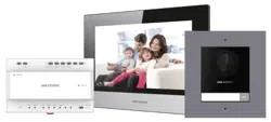
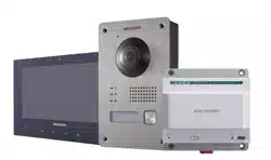
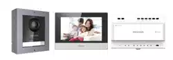
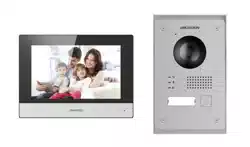
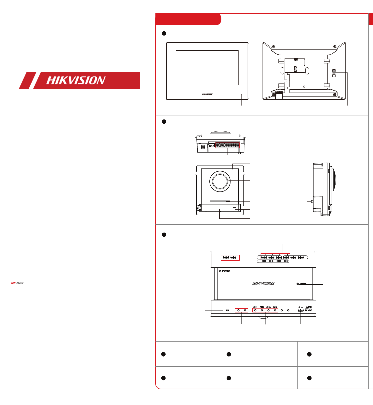
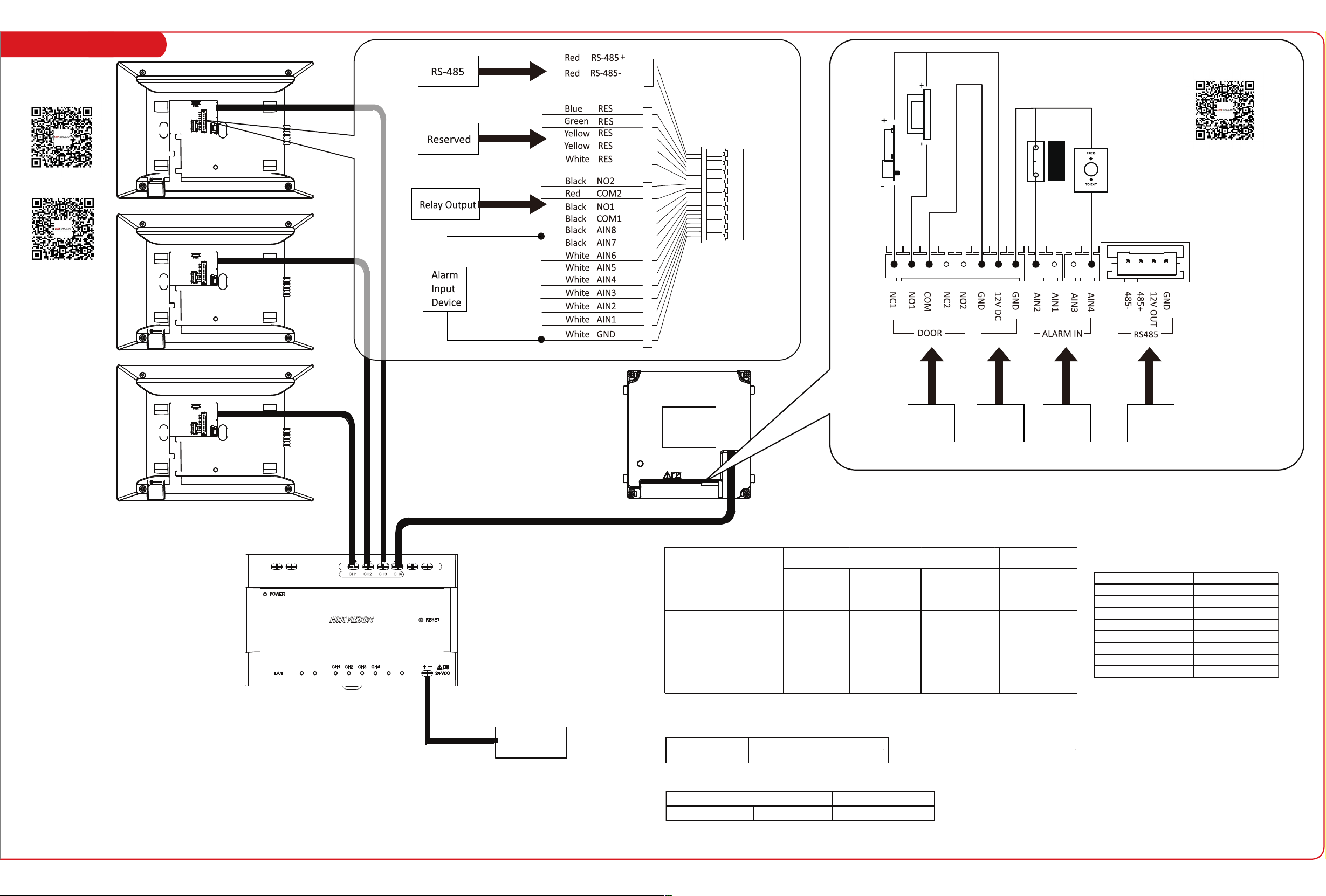
Devices in Kit 1 System Wiring
Door Station
Video/Audio Distributor
Indoor Station
IN
OUT
MAX
4W
24VDC
MAX
8W
IN
OUT
24 VDC
Power Input
Note:
The power adapter is contained only in the Kit.
Model Manufacturer
KPL-060M-II Channel Well Technology Co., Ltd
The detail for the power adapter contained in the package is as follows:
Exit Button
Door
Contact
Relay
Output
Power
Input
Alarm
Input
Device
RS-485
Electric
Strike
Electric
Dropbolt
The main module & the sub-module maximum power
consumption:
CH1 to CH3 can wire with indoor staions or 1 main module.
CH4 can wire with main module and sub modules.
The total consumption of all modules should no more than
the consumption of the distributor.
For example, the total consumption of door station with all
modules should be less than 10 W, which can be wired with
CH4.
Effective output power from each port of two-wire distributors:
Modules Power Consumption
DS-KD8003-IMEx 4 W
DS-KD-KK 0.8 W
DS-KD-KP 1 W
DS-KD-DIS 2.5 W
DS-KD-TD(M/E) 4 W
DS-KD-E 0.8 W
DS-KD-M 0.8 W
DS-KD-INFO 1.5 W
Power Consumption
CH1-CH4 10 W
Modules
Distributor
24AWG(0.2 mm²,
9 Ω/100 m)
20AWG(0.5 mm²,
3.5 Ω/100 m)
18AWG(0.8 mm²,
2.5 Ω/100 m)
All
DS-KAD702EY-DS- KD8003Y-
IME2
Transmission
Distance ≤ 35 m
Transmission
Distance ≤ 35 m
Transmission
Distance ≤ 35 m
Transmission
Distance ≤ 60 m
Transmission
Distance ≤ 60 m
DS-KAD702EY-DS-KH6320EY-
WTE2
Transmission
Distance ≤ 35 m
Transmission
Distance ≤ 60 m
Transmission
Distance ≤ 60 m
Twisted Pair Parallel lines
Routing Path
Display Screen
Microphone TF Card Slot Alarm Terminal
Loudspeaker
Debugging Port Two-Wire Interface
Microphone
Two-Wire
Interface
Module-connecting Interface
Terminals
Low Illumination IR Light
Built-in Camera
Loudspeaker
TAMPER
Call Button
Nametag
IN
OUT
MAX
4W
24VDC
MAX
8W
IN
OUT
Power Indicator
Cascade Interface
Cascade
Network
Indicator
Network
Indicator
Power Input
Reset Button
LAN
Terminals
Indoor Station
Main Unit
Video/Audio Distributor
TF Card
Mounting Plate Bracket Screws
DIN Rail Power Supply Wiring Terminal
User Manual of Door Station
Configuration Guide
of Indoor Station
Operation Guide of
Indoor Station
Villa Two Wire Kit
Quick Start Guide
UD30792B-C
©2022 Hangzhou Hikvision Digital Technology Co., Ltd. All rights reserved.
About this Manual
The Manual includes instruc�ons for using and managing the Product. Pictures, charts, images and all
other informa�on hereina�er are for descrip�on and explana�on only. The informa�on contained in the
Manual is subject to change, without no�ce, due to rmware updates or other reasons. Please nd the
latest version of this Manual at the Hikvision website (h�ps://www.hikvision.com/).
Please use this Manual with the guidance and assistance of professionals trained in suppor�ng the Product.
Trademarks
and other Hikvision’s trademarks and logos are the proper�es of Hikvision in various jurisdic�ons.
Other trademarks and logos men�oned are the proper�es of their respec�ve owners.
Disclaimer
TO THE MAXIMUM EXTENT PERMITTED BY APPLICABLE LAW, THIS MANUAL AND THE PRODUCT
DESCRIBED, WITH ITS HARDWARE, SOFTWARE AND FIRMWARE, ARE PROVIDED “AS IS” AND “WITH ALL
FAULTS AND ERRORS”. HIKVISION MAKES NO WARRANTIES, EXPRESS OR IMPLIED, INCLUDING WITHOUT
LIMITATION, MERCHANTABILITY, SATISFACTORY QUALITY, OR FITNESS FOR A PARTICULAR PURPOSE. THE
USE OF THE PRODUCT BY YOU IS AT YOUR OWN RISK. IN NO EVENT WILL HIKVISION BE LIABLE TO YOU FOR
ANY SPECIAL, CONSEQUENTIAL, INCIDENTAL, OR INDIRECT DAMAGES, INCLUDING, AMONG OTHERS,
DAMAGES FOR LOSS OF BUSINESS PROFITS, BUSINESS INTERRUPTION, OR LOSS OF DATA, CORRUPTION OF
SYSTEMS, OR LOSS OF DOCUMENTATION, WHETHER BASED ON BREACH OF CONTRACT, TORT (INCLUDING
NEGLIGENCE), PRODUCT LIABILITY, OR OTHERWISE, IN CONNECTION WITH THE USE OF THE PRODUCT,
EVEN IF HIKVISION HAS BEEN ADVISED OF THE POSSIBILITY OF SUCH DAMAGES OR LOSS.
YOU ACKNOWLEDGE THAT THE NATURE OF THE INTERNET PROVIDES FOR INHERENT SECURITY RISKS, AND
HIKVISION SHALL NOT TAKE ANY RESPONSIBILITIES FOR ABNORMAL OPERATION, PRIVACY LEAKAGE OR
OTHER DAMAGES RESULTING FROM CYBER-ATTACK, HACKER ATTACK, VIRUS INFECTION, OR OTHER
INTERNET SECURITY RISKS; HOWEVER, HIKVISION WILL PROVIDE TIMELY TECHNICAL SUPPORT IF
REQUIRED.
YOU AGREE TO USE THIS PRODUCT IN COMPLIANCE WITH ALL APPLICABLE LAWS, AND YOU ARE SOLELY
RESPONSIBLE FOR ENSURING THAT YOUR USE CONFORMS TO THE APPLICABLE LAW. ESPECIALLY, YOU ARE
RESPONSIBLE, FOR USING THIS PRODUCT IN A MANNER THAT DOES NOT INFRINGE ON THE RIGHTS OF
THIRD PARTIES, INCLUDING WITHOUT LIMITATION, RIGHTS OF PUBLICITY, INTELLECTUAL PROPERTY
RIGHTS, OR DATA PROTECTION AND OTHER PRIVACY RIGHTS. YOU SHALL NOT USE THIS PRODUCT FOR ANY
PROHIBITED END-USES, INCLUDING THE DEVELOPMENT OR PRODUCTION OF WEAPONS OF MASS
DESTRUCTION, THE DEVELOPMENT OR PRODUCTION OF CHEMICAL OR BIOLOGICAL WEAPONS, ANY
ACTIVITIES IN THE CONTEXT RELATED TO ANY NUCLEAR EXPLOSIVE OR UNSAFE NUCLEAR FUEL-CYCLE, OR
IN SUPPORT OF HUMAN RIGHTS ABUSES.
IN THE EVENT OF ANY CONFLICTS BETWEEN THIS MANUAL AND THE APPLICABLE LAW, THE LATTER
PREVAILS.
Data Protec�on
During the use of device, personal data will be collected, stored and processed. To protect data, the
development of Hikvision devices incorporates privacy by design principles. For example, for device with
facial recogni�on features, biometrics data is stored in your device with encryp�on method; for ngerprint
device, only ngerprint template will be saved, which is impossible to reconstruct a ngerprint image.
As data controller, you are advised to collect, store, process and transfer data in accordance with the
applicable data protec�on laws and regula�ons, including without limita�on, conduc�ng security controls
to safeguard personal data, such as, implemen�ng reasonable administra�ve and physical security
controls, conduct periodic reviews and assessments of the eec�veness of your security controls.
Devices in Kit 1 System Wiring
Door Station
Video/Audio Distributor
Indoor Station
IN
OUT
MAX
4W
24VDC
MAX
8W
IN
OUT
24 VDC
Power Input
Note:
The power adapter is contained only in the Kit.
Model Manufacturer
KPL-060M-II Channel Well Technology Co., Ltd
The detail for the power adapter contained in the package is as follows:
Exit Button
Door
Contact
Relay
Output
Power
Input
Alarm
Input
Device
RS-485
Electric
Strike
Electric
Dropbolt
The main module & the sub-module maximum power
consumption:
CH1 to CH3 can wire with indoor staions or 1 main module.
CH4 can wire with main module and sub modules.
The total consumption of all modules should no more than
the consumption of the distributor.
For example, the total consumption of door station with all
modules should be less than 10 W, which can be wired with
CH4.
Effective output power from each port of two-wire distributors:
Modules Power Consumption
DS-KD8003-IMEx 4 W
DS-KD-KK 0.8 W
DS-KD-KP 1 W
DS-KD-DIS 2.5 W
DS-KD-TD(M/E) 4 W
DS-KD-E 0.8 W
DS-KD-M 0.8 W
DS-KD-INFO 1.5 W
Power Consumption
CH1-CH4 10 W
Modules
Distributor
24AWG(0.2 mm²,
9 Ω/100 m)
20AWG(0.5 mm²,
3.5 Ω/100 m)
18AWG(0.8 mm²,
2.5 Ω/100 m)
All
DS-KAD702EY-DS- KD8003Y-
IME2
Transmission
Distance ≤ 35 m
Transmission
Distance ≤ 35 m
Transmission
Distance ≤ 35 m
Transmission
Distance ≤ 60 m
Transmission
Distance ≤ 60 m
DS-KAD702EY-DS-KH6320EY-
WTE2
Transmission
Distance ≤ 35 m
Transmission
Distance ≤ 60 m
Transmission
Distance ≤ 60 m
Twisted Pair Parallel lines
Routing Path
Display Screen
Microphone TF Card Slot Alarm Terminal
Loudspeaker
Debugging Port Two-Wire Interface
Microphone
Two-Wire
Interface
Module-connecting Interface
Terminals
Low Illumination IR Light
Built-in Camera
Loudspeaker
TAMPER
Call Button
Nametag
IN
OUT
MAX
4W
24VDC
MAX
8W
IN
OUT
Power Indicator
Cascade Interface
Cascade
Network
Indicator
Network
Indicator
Power Input
Reset Button
LAN
Terminals
Indoor Station
Main Unit
Video/Audio Distributor
TF Card
Mounting Plate Bracket Screws
DIN Rail Power Supply Wiring Terminal
User Manual of Door Station
Configuration Guide
of Indoor Station
Operation Guide of
Indoor Station
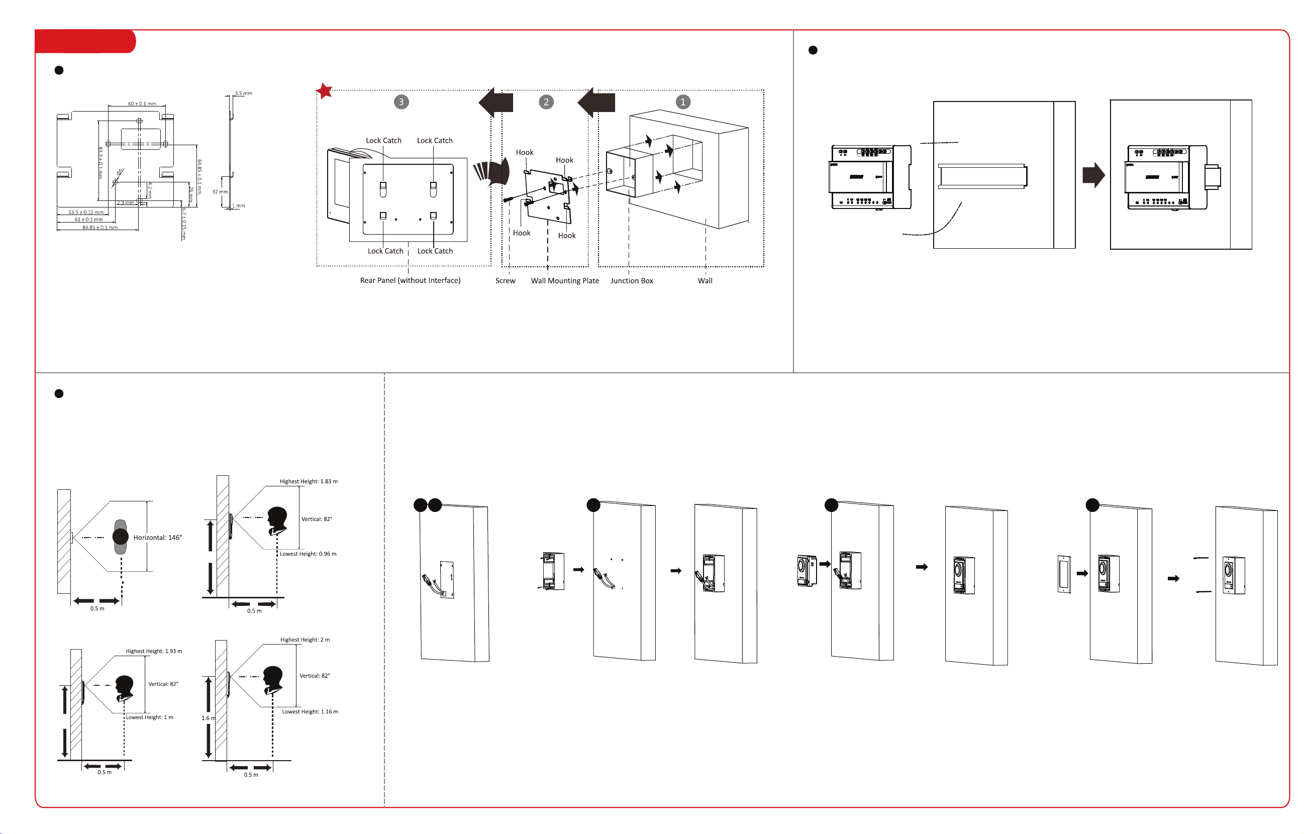
2 Installation 3 Quick Operation
1. Tools for installation you need to prepare: Drill (6), cross screw driver (PH1*150 mm), and gradienter.
2. Make sure all the related equipments are power-o during the installation.
Before you begin:
Note:
1. Here takes flush mounting as an example.
2. The power source should be qualified and meet limited power source or PS2 requirements according to
IEC 60950-1 or IEC 62368-1 standard.
3. Remote the mounting template. and fix the
moun�ng frame to the wall with 4 expansion
bolts.
4. Wire the main unit and the cables across the
thread holes of the frame. Put the main unit in
the frame.
5. Use the hexagon wrench in the package to x
the cover onto the frame.
2. Drill 4 holes according the mounting plate with the
drill size of 6. The depth of each hole is 25 mm.
Insert the expansion sleeves into the screw holes.
1. Paste the installa�on mounting template onto the
wall. Make sure the mounting template is placed
horizontally via measuring with the gradienter. Drill
4 holes according to the screw holes on the s�cker.
Note: The suggested length of the cables le�
outside is 100 mm.
The wall mounting plate and the junction box are required to install the
indoor station onto the wall.
The dimension of junction box should be 75 mm (width) × 75 mm
(length) × 50 mm (depth).
The dimension of wall mounting plate is shown.
1. Tools that you need to prepare for installation:
Make sure the device in the package is in good
condition and all the assembly parts are included.
2. The power supply the indoor station supports is 24 VDC.
Make sure your power supply matches your indoor station.
3. Make sure all related equipments are power-o during the installation.
4. Check the product specication for the installation environment.
Before you begin:
Steps:
1. Chisel a hole in the wall. The size of the hole should be 76 mm (width) × 76 mm (length) × 50 mm (depth).
Insert the junction box to the hole chiseled on the wall.
2. Fix the wall mounting plate to the junction box with 2 screws.
3. Hook the indoor station to the wall mounting plate tightly by
inserting the plate hooks into the slots on the rear panel of the
indoor station, during which the lock catch will be locked automatically.
Mounting Plate Dimension
Before you begin:
Make sure the device in the package is in good
condition.
Make sure all the related equipment is power-off
during the installation. Check the product specification
for the installation environment.
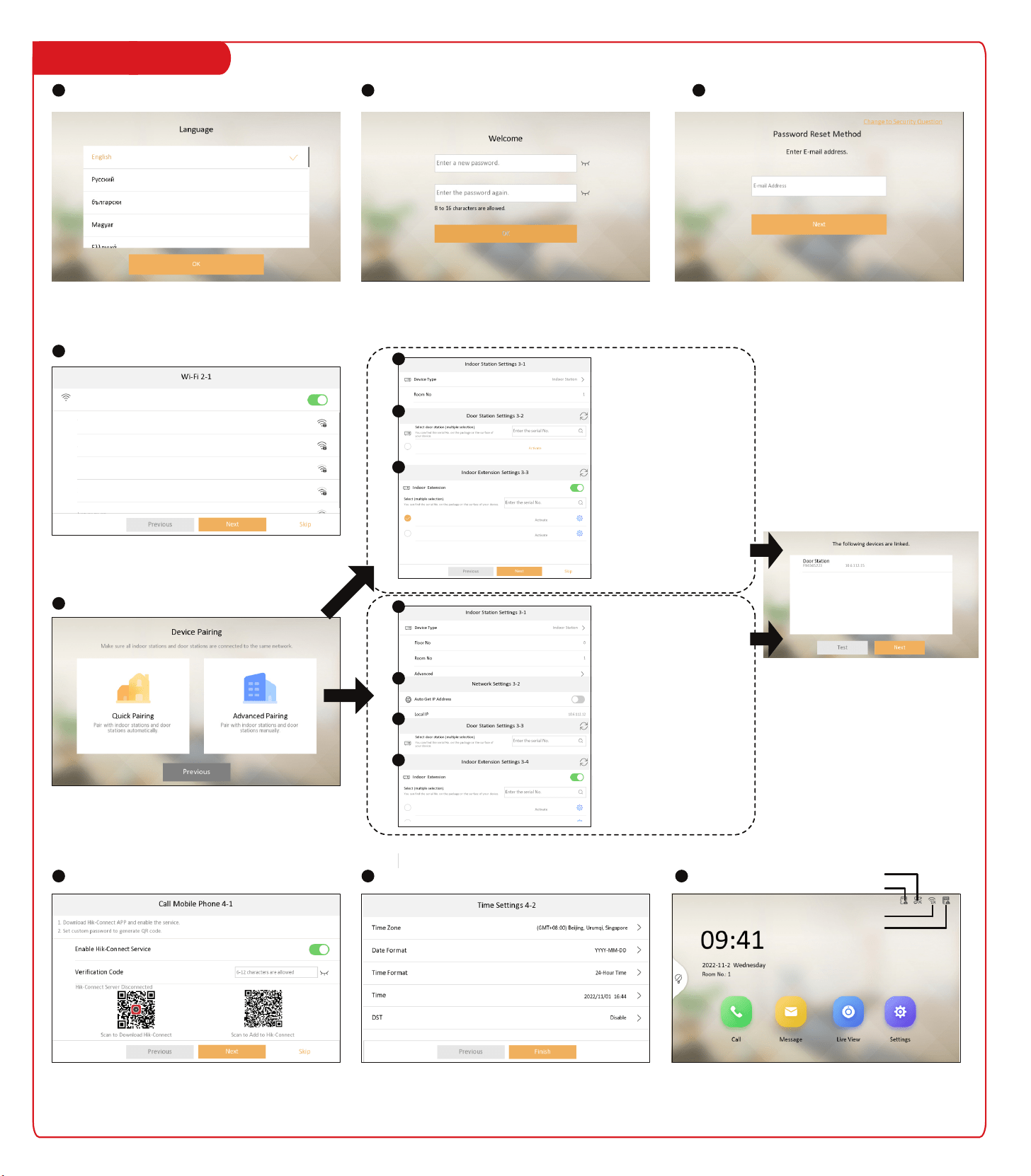
Create activation password for the device. 8 to 16
characters are allowed.
Enable the device Wi-Fi function, and select Wi-Fi. Enter the
Wi-Fi's password. If the device has already connected to a
wired network, skip the step.
You can choose to reset the activation/admin password via the
email or security questions if you forget your password.
Choose language according to your actual needs.
After language selection, you should follow the instructions to
finish the wizard.
Quick pairing:
For normal operators who are
not expert at setting network
parameters. The indoor
station and the door station
will be paired automatically.
Set the indoor station's room
No., select the door station,
and indoor extension.
If there are multiple door
stations, tap Main to set the
door station as main door
station.
Quick
pairing
Steps:
1. Fix the DIN rail onto the wall.
Note: You are required to utilize a matched DIN rail.
2. Press the red clip upward, and lock it to the DIN rail.
Recommended Installation Height (The distance between the camera and the ground): 1.4 m to 1.6 m.
The FOV of the camera is : Horizontal: 146°, Vertical: 82°.
The highest visual height and lowest visual height of the camera is shown as picture.
1.5 m
1.4 m
Select Language
1
Set Wi-Fi
4
Pair Device
5
Set Hik-Connect Service
6
Home Page
Set Email/Security Question
Install Indoor Station
Install Main Unit
Install Distributor
Activate Device
2
1 2 3 4 5
TF Card Status
Door Station Status
Wi-Fi Status
Hik-Connect Status
Advanced Pairing:
For experts who can set network
parameters. The indoor station
and the door station can be
paired manually.
Set the indoor station's floor No.,
room No., build No., unit No., set
the indoor station's wired
network, select the door station
and the indoor extension.
If there are multiple door
stations, tap Main to set the
door station as main door
station.
After the devices are paired, tap Test. The
video intercom will be completed done if the
devices are connected properly.
If exceptions occurred, the status icon will be changed at the
upper right corner of the screen. Tap the icon and follow the
instructions to solve.
3
Advanced
pairing
a
b
c
Set Time
7
a
b
c
d
XXXX
XXXXXXXXXXXXXX
XXXX
XXXXXXXXXXXXXX
XXXX
XXXXXXXXXXXXXX
XXXX
XXXXXXXXXXXXXX
XXXX
XX.XX.XXX.XX
XX.XX.XXX.XX
XX.XX.XXX.XX
XX.XX.XXX.XX
VXXX Build XXXXX
VXXX Build XXXXX
VXXX Build XXXXX
VXXX Build XXXXX
XXXX
XXXX
XXXX
XXXX
XXXX
2 Installation 3 Quick Operation
1. Tools for installation you need to prepare: Drill (6), cross screw driver (PH1*150 mm), and gradienter.
2. Make sure all the related equipments are power-o during the installation.
Before you begin:
Note:
1. Here takes flush mounting as an example.
2. The power source should be qualified and meet limited power source or PS2 requirements according to
IEC 60950-1 or IEC 62368-1 standard.
3. Remote the mounting template. and fix the
moun�ng frame to the wall with 4 expansion
bolts.
4. Wire the main unit and the cables across the
thread holes of the frame. Put the main unit in
the frame.
5. Use the hexagon wrench in the package to x
the cover onto the frame.
2. Drill 4 holes according the mounting plate with the
drill size of 6. The depth of each hole is 25 mm.
Insert the expansion sleeves into the screw holes.
1. Paste the installa�on mounting template onto the
wall. Make sure the mounting template is placed
horizontally via measuring with the gradienter. Drill
4 holes according to the screw holes on the s�cker.
Note: The suggested length of the cables le�
outside is 100 mm.
The wall mounting plate and the junction box are required to install the
indoor station onto the wall.
The dimension of junction box should be 75 mm (width) × 75 mm
(length) × 50 mm (depth).
The dimension of wall mounting plate is shown.
1. Tools that you need to prepare for installation:
Make sure the device in the package is in good
condition and all the assembly parts are included.
2. The power supply the indoor station supports is 24 VDC.
Make sure your power supply matches your indoor station.
3. Make sure all related equipments are power-o during the installation.
4. Check the product specication for the installation environment.
Before you begin:
Steps:
1. Chisel a hole in the wall. The size of the hole should be 76 mm (width) × 76 mm (length) × 50 mm (depth).
Insert the junction box to the hole chiseled on the wall.
2. Fix the wall mounting plate to the junction box with 2 screws.
3. Hook the indoor station to the wall mounting plate tightly by
inserting the plate hooks into the slots on the rear panel of the
indoor station, during which the lock catch will be locked automatically.
Mounting Plate Dimension
Before you begin:
Make sure the device in the package is in good
condition.
Make sure all the related equipment is power-off
during the installation. Check the product specification
for the installation environment.
Create activation password for the device. 8 to 16
characters are allowed.
Enable the device Wi-Fi function, and select Wi-Fi. Enter the
Wi-Fi's password. If the device has already connected to a
wired network, skip the step.
You can choose to reset the activation/admin password via the
email or security questions if you forget your password.
Choose language according to your actual needs.
After language selection, you should follow the instructions to
finish the wizard.
Quick pairing:
For normal operators who are
not expert at setting network
parameters. The indoor
station and the door station
will be paired automatically.
Set the indoor station's room
No., select the door station,
and indoor extension.
If there are multiple door
stations, tap Main to set the
door station as main door
station.
Quick
pairing
Steps:
1. Fix the DIN rail onto the wall.
Note: You are required to utilize a matched DIN rail.
2. Press the red clip upward, and lock it to the DIN rail.
Recommended Installation Height (The distance between the camera and the ground): 1.4 m to 1.6 m.
The FOV of the camera is : Horizontal: 146°, Vertical: 82°.
The highest visual height and lowest visual height of the camera is shown as picture.
1.5 m
1.4 m
Select Language
1
Set Wi-Fi
4
Pair Device
5
Set Hik-Connect Service
6
Home Page
Set Email/Security Question
Install Indoor Station
Install Main Unit
Install Distributor
Activate Device
2
1 2 3 4 5
TF Card Status
Door Station Status
Wi-Fi Status
Hik-Connect Status
Advanced Pairing:
For experts who can set network
parameters. The indoor station
and the door station can be
paired manually.
Set the indoor station's floor No.,
room No., build No., unit No., set
the indoor station's wired
network, select the door station
and the indoor extension.
If there are multiple door
stations, tap Main to set the
door station as main door
station.
After the devices are paired, tap Test. The
video intercom will be completed done if the
devices are connected properly.
If exceptions occurred, the status icon will be changed at the
upper right corner of the screen. Tap the icon and follow the
instructions to solve.
3
Advanced
pairing
a
b
c
Set Time
7
a
b
c
d
XXXX
XXXXXXXXXXXXXX
XXXX
XXXXXXXXXXXXXX
XXXX
XXXXXXXXXXXXXX
XXXX
XXXXXXXXXXXXXX
XXXX
XX.XX.XXX.XX
XX.XX.XXX.XX
XX.XX.XXX.XX
XX.XX.XXX.XX
VXXX Build XXXXX
VXXX Build XXXXX
VXXX Build XXXXX
VXXX Build XXXXX
XXXX
XXXX
XXXX
XXXX
XXXX