
Terminal Server
User Manual

Legal Informaon
©2022 Hangzhou Hikvision Digital Technology Co., Ltd. All rights reserved.
About this Manual
The Manual includes instrucons for using and managing the Product. Pictures, charts, images and
all other informaon hereinaer are for descripon and explanaon only. The informaon
contained in the Manual is subject to change, without noce, due to rmware updates or other
reasons. Please nd the latest version of this Manual at the Hikvision website ( hps://
www.hikvision.com/ ).
Please use this Manual with the guidance and assistance of professionals trained in
supporng the
Product.
Trademarks
and other Hikvision's trademarks and logos are the properes of
Hikvision in various jurisdicons.
Other trademarks and logos menoned are the properes of their respecve owners.
Disclaimer
TO THE MAXIMUM EXTENT PERMITTED BY APPLICABLE LAW, THIS MANUAL AND THE PRODUCT
DESCRIBED, WITH ITS HARDWARE, SOFTWARE AND FIRMWARE, ARE PROVIDED "AS IS" AND "WITH
ALL FAULTS AND ERRORS". HIKVISION MAKES NO WARRANTIES, EXPRESS OR IMPLIED, INCLUDING
WITHOUT LIMITATION, MERCHANTABILITY, SATISFACTORY QUALITY, OR FITNESS FOR A PARTICULAR
PURPOSE. THE USE OF THE PRODUCT BY YOU IS AT YOUR OWN RISK. IN NO EVENT WILL HIKVISION
BE LIABLE TO YOU FOR ANY SPECIAL, CONSEQUENTIAL, INCIDENTAL, OR INDIRECT DAMAGES,
INCLUDING, AMONG OTHERS, DAMAGES FOR LOSS OF BUSINESS PROFITS, BUSINESS
INTERRUPTION, OR LOSS OF DATA, CORRUPTION OF SYSTEMS, OR LOSS OF DOCUMENTATION,
WHETHER BASED ON BREACH OF CONTRACT, TORT (INCLUDING NEGLIGENCE), PRODUCT LIABILITY,
OR OTHERWISE, IN CONNECTION WITH THE USE OF THE PRODUCT, EVEN IF HIKVISION HAS BEEN
ADVISED OF THE POSSIBILITY OF SUCH DAMAGES OR LOSS.
YOU ACKNOWLEDGE THAT THE NATURE OF THE INTERNET PROVIDES FOR INHERENT SECURITY
RISKS, AND HIKVISION SHALL NOT TAKE ANY RESPONSIBILITIES FOR ABNORMAL OPERATION,
PRIVACY LEAKAGE OR OTHER DAMAGES RESULTING FROM CYBER-ATTACK, HACKER ATTACK, VIRUS
INFECTION, OR OTHER INTERNET SECURITY RISKS; HOWEVER, HIKVISION WILL PROVIDE TIMELY
TECHNICAL SUPPORT IF REQUIRED.
YOU AGREE TO USE THIS PRODUCT IN COMPLIANCE WITH ALL APPLICABLE LAWS, AND YOU ARE
SOLELY RESPONSIBLE FOR ENSURING THAT YOUR USE CONFORMS TO THE APPLICABLE LAW.
ESPECIALLY, YOU ARE RESPONSIBLE, FOR USING THIS PRODUCT IN A MANNER THAT DOES NOT
INFRINGE ON THE RIGHTS OF THIRD PARTIES, INCLUDING WITHOUT LIMITATION, RIGHTS OF
PUBLICITY, INTELLECTUAL PROPERTY RIGHTS, OR DATA PROTECTION AND OTHER PRIVACY RIGHTS.
YOU SHALL NOT USE THIS PRODUCT FOR ANY PROHIBITED END-USES, INCLUDING THE
Terminal Server User Manual
i

DEVELOPMENT OR PRODUCTION OF WEAPONS OF MASS DESTRUCTION, THE DEVELOPMENT OR
PRODUCTION OF CHEMICAL OR BIOLOGICAL WEAPONS, ANY ACTIVITIES IN THE CONTEXT RELATED
TO ANY NUCLEAR EXPLOSIVE OR UNSAFE NUCLEAR FUEL-CYCLE, OR IN SUPPORT OF HUMAN
RIGHTS ABUSES.
IN THE EVENT OF ANY CONFLICTS BETWEEN THIS MANUAL AND THE APPLICABLE LAW, THE LATTER
PREVAILS.
Terminal Server User Manual
ii
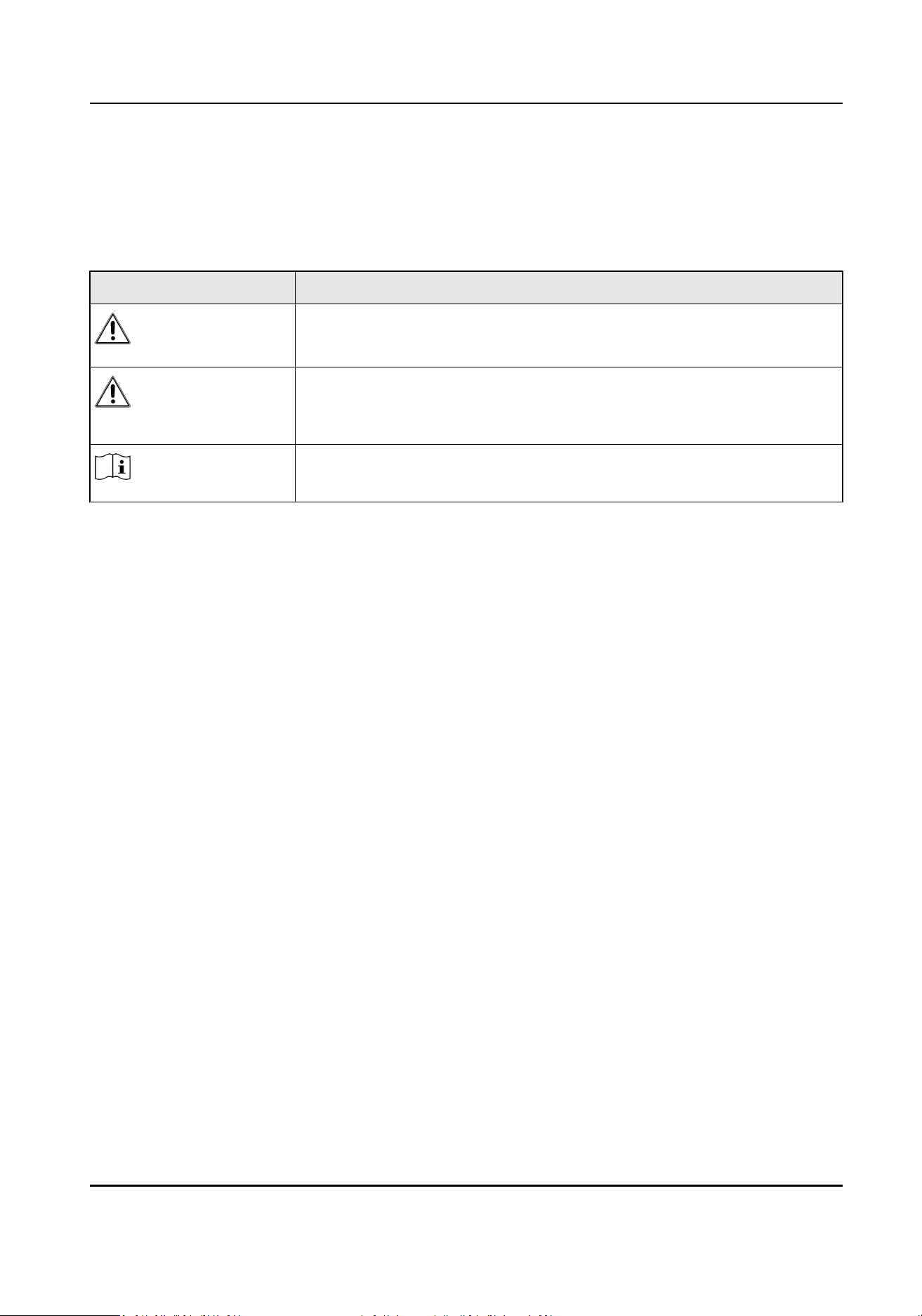
Symbol Convenons
The symbols that may be found in this document are dened as follows.
Symbol Descripon
Danger
Indicates a hazardous situaon which, if not avoided, will or could
result in death or serious injury.
Cauon
Indicates a potenally hazardous situaon which, if not avoided, could
result in equipment damage, data loss, performance degradaon, or
unexpected results.
Note
Provides addional informaon to emphasize or supplement
important points of the main text.
Terminal Server User Manual
iii

Contents
Chapter 1 Introducon ............................................................................................................... 1
1.1 Product Introducon .............................................................................................................. 1
1.2 Key Feature ............................................................................................................................ 1
1.3 Running Environment ............................................................................................................ 1
Chapter 2 Acvaon and Login ................................................................................................... 2
2.1 Acvaon ............................................................................................................................... 2
2.1.1 Default Informaon ...................................................................................................... 2
2.1.2 Acvate via SADP .......................................................................................................... 2
2.1.3
Acvate via Web Browser ............................................................................................. 3
2.2 Login ...................................................................................................................................... 4
Chapter 3 Basic Operaon .......................................................................................................... 5
3.1 Set LAN IP Address ................................................................................................................. 5
3.1.1 Set Internal IP ................................................................................................................ 5
3.1.2 Set External IP ............................................................................................................... 6
3.2 Set
Stac Router .................................................................................................................... 7
3.3 Manage Camera ..................................................................................................................... 8
3.3.1 Add IP Camera ............................................................................................................... 8
3.3.2 Set
Interacon Parameters ......................................................................................... 10
3.4 Set Remote Host .................................................................................................................. 10
Chapter 4 Event Detecon and Face Recognion ...................................................................... 12
4.1 Set Vehicle Arming ............................................................................................................... 12
4.2 Set Event Parameters ........................................................................................................... 13
4.2.1 Set Camera Parameters ............................................................................................... 13
4.2.2 Set
Violaon Diconary .............................................................................................. 14
Chapter 5 Data Management .................................................................................................... 15
5.1 View Real-Time Data ............................................................................................................ 15
Terminal Server User Manual
iv

5.2 Search Data .......................................................................................................................... 15
5.3 Enable Trac Parameters Stascs ..................................................................................... 15
5.4 View
Trac Stascs ........................................................................................................... 16
5.5 Back up Data ........................................................................................................................ 16
5.5.1 Back up to Local .......................................................................................................... 16
5.5.2 Back up to USB ............................................................................................................ 17
Chapter 6 Live View and Local Conguraon ............................................................................ 18
6.1 Live View .............................................................................................................................. 18
6.1.1 Start/Stop Live View .................................................................................................... 18
6.1.2 Divide Window and Switch Page ................................................................................. 18
6.1.3 Select Stream Type ...................................................................................................... 18
6.1.4 Capture Manually ........................................................................................................ 19
6.1.5 Record Manually ......................................................................................................... 19
6.1.6 Enable/Disable Audio .................................................................................................. 19
6.1.7 Enable Digital Zoom .................................................................................................... 19
6.1.8 Display in Full Screen .................................................................................................. 20
6.2 PTZ Control .......................................................................................................................... 20
6.2.1 PTZ Control Panel ........................................................................................................ 20
6.2.2 Set Preset .................................................................................................................... 21
6.3 Local
Conguraon .............................................................................................................. 21
Chapter 7 Network Conguraon ............................................................................................. 24
7.1 Dial ....................................................................................................................................... 24
7.2 Connect to ISUP
Plaorm .................................................................................................... 25
7.3 Set DDNS .............................................................................................................................. 26
7.4 Set Port ................................................................................................................................ 27
7.5 Set SNMP ............................................................................................................................. 27
7.6 Set ONVIF ............................................................................................................................. 28
Chapter 8 Record and Playback ................................................................................................. 30
Terminal Server User Manual
v

8.1 Set Storage Path ................................................................................................................... 30
8.1.1 Format Disk ................................................................................................................. 30
8.1.2 Set FTP ........................................................................................................................ 30
8.1.3 Set Cloud Storage ........................................................................................................ 32
8.2 Set Quota ............................................................................................................................. 33
8.3 Record .................................................................................................................................. 33
8.3.1 Set Timing Record ....................................................................................................... 33
8.3.2 Set Event Record ......................................................................................................... 34
8.4 Play Back Video .................................................................................................................... 35
8.5 Backup ................................................................................................................................. 36
8.5.1 Back up Video ............................................................................................................. 36
8.5.2 Back up Clipped Video ................................................................................................ 36
Chapter 9 Encoding and Display ................................................................................................ 38
9.1 Set Video Encoding Parameters ........................................................................................... 38
9.2 Set Image Parameters .......................................................................................................... 39
9.3 Set OSD ................................................................................................................................ 39
Chapter 10 Alarm Congifuraon ............................................................................................... 41
10.1 Set Alarm Input .................................................................................................................. 41
10.2 Set Alarm Output ............................................................................................................... 41
10.3 Set
Excepon Alarm ........................................................................................................... 42
10.4 Set Record Schedule .......................................................................................................... 43
10.5 Set Holiday ......................................................................................................................... 44
10.6 Set Linkage Mode ............................................................................................................... 44
Chapter 11 Safety Management ............................................................................................... 45
11.1 Manage User ...................................................................................................................... 45
11.2 Install Authorized
Cercate ............................................................................................. 45
11.3 Create and Install Self-signed Cercate ........................................................................... 46
11.4 Set SSH ............................................................................................................................... 46
Terminal Server User Manual
vi

11.5 Set Session Expired Time ................................................................................................... 46
Chapter 12 Maintenance .......................................................................................................... 47
12.1 View Device
Informaon .................................................................................................... 47
12.2 Search Log .......................................................................................................................... 47
12.3 Upgrade ............................................................................................................................. 47
12.4 Reboot ............................................................................................................................... 48
12.5 Restore Parameters ............................................................................................................ 48
12.6 Restore Database ............................................................................................................... 48
12.7 Set RS-485 .......................................................................................................................... 49
12.8 Set RS-232 .......................................................................................................................... 49
12.9 Synchronize Camera Time .................................................................................................. 50
12.10 Synchronize Time ............................................................................................................. 50
12.11 Set DST ............................................................................................................................. 51
12.12 Export Parameters ........................................................................................................... 51
12.13 Import Parameters ........................................................................................................... 51
12.14 Detect HDD ...................................................................................................................... 52
12.15 Set Working Mode ........................................................................................................... 52
12.16 Reserved Parameters ....................................................................................................... 54
Appendix A.
Communicaon Matrix and Device Command ...................................................... 55
Terminal Server User Manual
vii

Chapter 1 Introducon
1.1 Product Introducon
Terminal server, as an outdoor network video recorder in the trac eld, integrates mulple
funcons like storage management, trac data management, video and audio decoding, picture
processing, and network switching. It adopts the embedded, switchable, and hybrid hard disk
recording design, which meets the demands for front-end distributed storage and forms a set of
security system with the help of the network access plaorm management center. It is used to
receive, store, and process data in the scene of expressway, urban road, tunnel, etc.
1.2 Key Feature
●
Supports connecng to various types of cameras.
●
Solid, compact, fan-free, and small-sized, applicable to various scenarios such as roadside
cabinet and pole mounted cabinet.
●
Interfaces designed on a single panel, which makes it easy for construcons and operaons.
●
Supports large-capacity storage.
●
Supports web
operaons and SDK.
1.3 Running Environment
●
Browser: IE 8.0 and above versions recommended.
●
Resoluon: 1024 × 768 and above.
Terminal Server User Manual
1

Chapter 2 Acvaon and Login
2.1 Acvaon
For the rst-me access, you need to acvate the device by seng an admin password. No
operaon is allowed before acvaon. The device supports mulple acvaon methods, such as
acvaon via SADP soware, web browser, and iVMS-4200 Client.
Note
Refer to the user manual of iVMS-4200 Client for the acvaon via client soware.
2.1.1 Default Informaon
The device default informaon is shown as below.
●
Default IP address: The default IP address for G1 network interface is 192.1.0.64. The default IP
address for G2 network interface is 192.168.1.64.
●
Default user name: admin.
2.1.2
Acvate via SADP
SADP is a tool to detect, acvate, and modify the IP address of the device over the LAN.
Before You Start
●
Get the SADP soware from the supplied disk or the ocial website ( hp://
www.hikvision.com/ ), and install it according to the prompts.
●
The device and the computer that runs the SADP tool should belong to the same network
segment.
The following steps show how to
acvate one device and modify its IP address. For batch acvaon
and IP address modicaon, refer to User Manual of SADP for details.
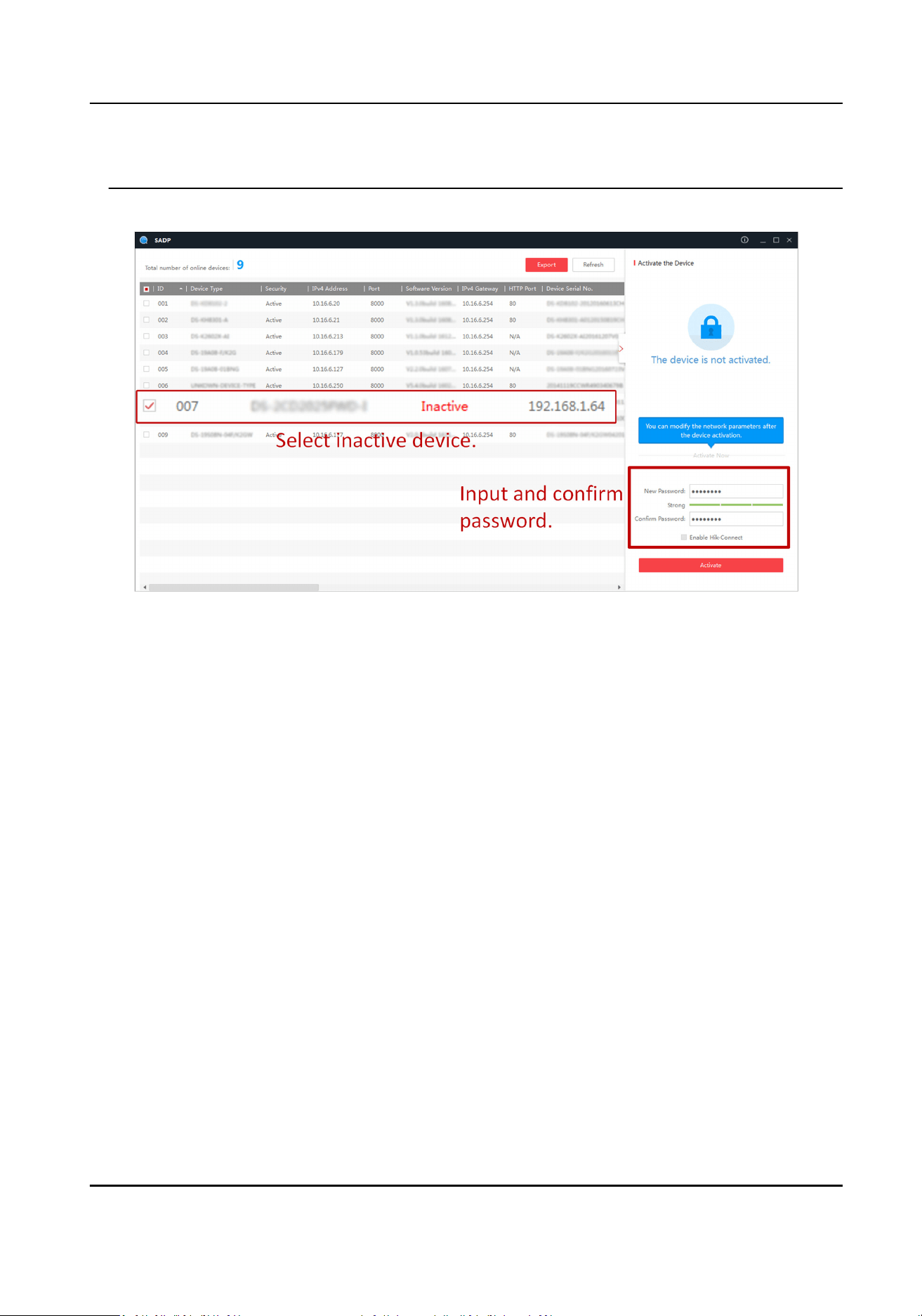
Steps
1.
Run the SADP soware and search the online devices.
2.
Find and select your device in online device list.
3.
Enter a new password (admin password) and
conrm the password.
Cauon
STRONG PASSWORD RECOMMENDED-We highly recommend you create a strong password of
your own choosing (using a minimum of 8 characters, including upper case leers, lower case
leers, numbers, and special characters) in order to increase the security of your product. And
Terminal Server User Manual
2
we recommend you reset your password regularly, especially in the high security system,
reseng the password monthly or weekly can beer protect your product.
4.
Click Acvate to start acvaon.
Figure 2-1 Acvate via SADP
Status of the device becomes Acve aer successful acvaon.
5.
Modify IP address of the device.
1) Select the device.
2) Change the device IP address to the same network segment as your computer by either
modifying the IP address manually or checking Enable DHCP (Dynamic Host
Conguraon
Protocol).
3) Enter the admin password and click Modify to acvate your IP address modicaon.
2.1.3
Acvate via Web Browser
Use web browser to acvate the device. For the device with the DHCP enabled by default, use
SADP soware or client soware to acvate the device.
Before You Start
Ensure the device and the computer connect to the same LAN.
Steps
1.
Change the IP address of your computer to the same network segment as the device.
2.
Open the web browser, and enter the default IP address of the device to enter the
acvaon
interface.
3.
Create and
conrm the admin password.
Terminal Server User Manual
3

Cauon
STRONG PASSWORD RECOMMENDED-We highly recommend you create a strong password of
your own choosing (using a minimum of 8 characters, including upper case leers, lower case
leers, numbers, and special characters) in order to increase the security of your product. And
we recommend you reset your password regularly, especially in the high security system,
reseng the password monthly or weekly can beer protect your product.
4.
Click OK to complete acvaon.
5.
Go to the network sengs interface to modify IP address of the device.
2.2 Login
You can log in to the device via web browser for further operaons such as live view and local
conguraon.
Before You Start
Connect the device to the network directly, or via a switch or a router.
Steps
1.
Open the web browser, and enter the IP address of the device to enter the login interface.
2.
Enter User Name and Password.
3.
Click Login.
4.
Download and install appropriate plug-in for your web browser. Follow the
installaon prompts
to install the plug-in.
5.
Reopen the web browser
aer the installaon of the plug-in and repeat steps 1 to 3 to login.
6.
Oponal: Click Logout on the upper right corner of the interface to log out of the device.
Terminal Server User Manual
4
Chapter 3 Basic Operaon
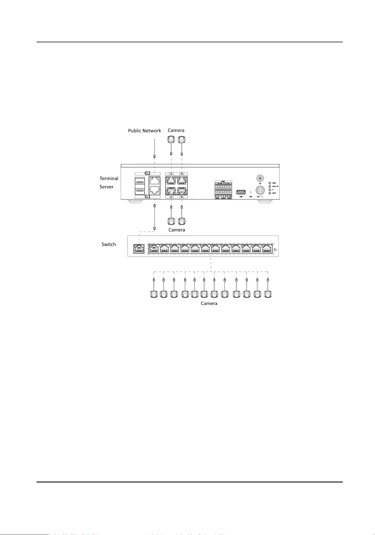
3.1 Set LAN IP Address
Complete connecons before seng networks.
Figure 3-1 Connecon Sample
3.1.1 Set Internal IP
The internal network is set for the IP of the G1 network interface on the device panel, and it is
mainly used to connect to the camera.
Steps
1.
Go to Param Cong → Network → Basic Sengs → TCP/IP → Internal Network Sengs .
Terminal Server User Manual
5
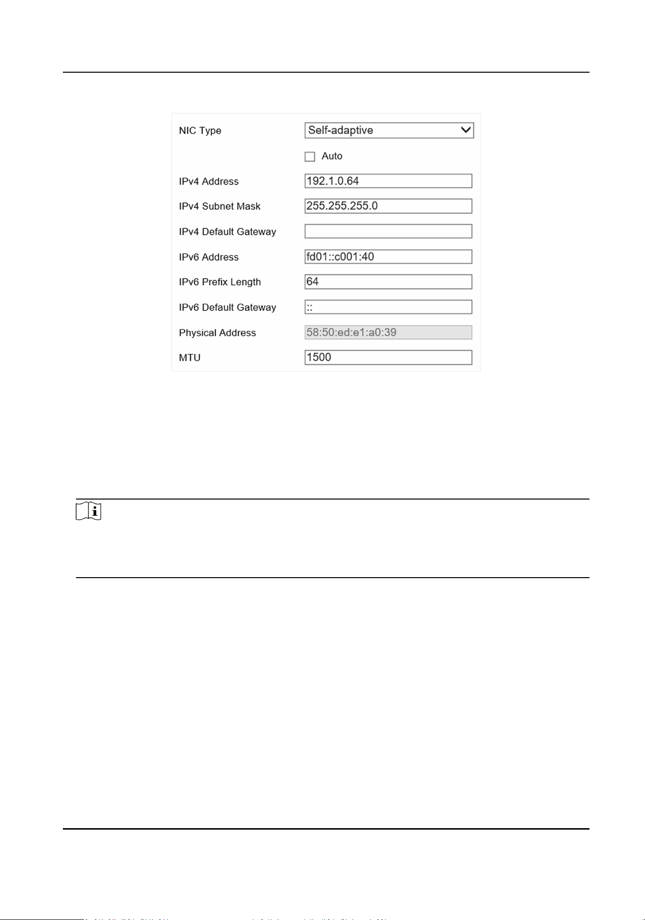
Figure 3-2 Set Internal IP
2.
Select NIC Type according to the actual network.
3.
Set relevant network parameters.
-
Check Auto to get the IPv4 and IPv6 addresses automacally if the network supports
distribung the IP addresses automacally.
-
Manually enter the IPv4 and IPv6 parameters and the MTU according to the actual network
condions.
Note
●
The internal IP address and the camera should be set to the same network segment, and it
must be set to a dierent network segment from that of the external IP address.
●
MTU stands for the maximum transmission unit in the network.
4.
Click Save.
3.1.2 Set External IP
The external network is set for the IP of the G2 network interface on the device panel, and it
mainly communicates with the external network
(plaorm, remote host, etc.).
Steps
1.
Go to Param Cong → Network → Basic Sengs → TCP/IP → External Network Sengs .
Terminal Server User Manual
6
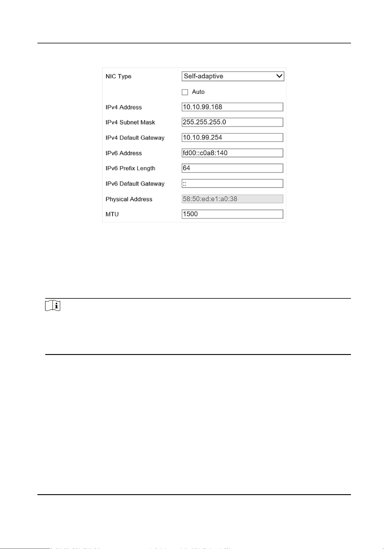
Figure 3-3 Set External IP
2.
Select NIC Type according to the actual network.
3.
Set relevant network parameters.
-
Check Auto to get the IPv4 and IPv6 addresses automacally if the network supports
distribung the IP addresses automacally.
-
Manually enter the IPv4 and IPv6 parameters and the MTU according to the actual network
condions.
Note
●
The network segment of external IP address should be dierent from that of the internal IP
address.
●
MTU stands for the maximum transmission unit in the network.
●
Set DNS Server if remote domain name access is needed.
4.
Click Save.
3.2 Set
Stac Router
Set a stac router for access across network segments. The device will transmit data as a router.
Steps
1.
Go to Param Cong → Network → Basic Sengs → Stac Router .
2.
Click Add to add a stac router.
Terminal Server User Manual
7
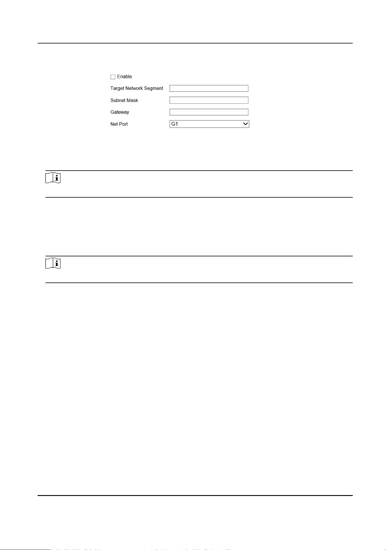
Figure 3-4 Set Stac Router
3.
Check Enable.
4.
Enter Target Network Segment, Subnet Mask, and Gateway.
Note
Set the gateway according to the selected network interface.
5.
Select the network interface that needs external communicaon for roung.
-
When you need other network segments to access the connected camera through the G1, set
the G1 as a stac router, and the internal IP address will serve as the gateway.
-
When you need to upload data to other network segments through the G2, set the G2 as a
stac router, and the external IP address will serve as the gateway.
6.
Click OK.
Note
The device supports deleng or eding the added router.
3.3 Manage Camera
3.3.1 Add IP Camera
Add cameras before managing and analyzing data.
Quick Add
If cameras need to be added via the parameters such as the default protocol and the port, it is
recommended to use quick add.
Before You Start
Connect the device to the camera via the network interface.
Steps
1.
Go to Param Cong → System → Camera Management → IP Camera .
2.
Click Quick Add.
Terminal Server User Manual
8
3.
Check the camera that need to be added, enter the corresponding user name and password,
and click OK.
Note
You can check cameras that have the same user name and password to add in batch.
4.
Oponal: You can also do the following operaons.
Edit Edit the added camera IP address.
Delete Delete the added camera.
Reboot Reboot the online camera.
Access Directly Access the online camera.
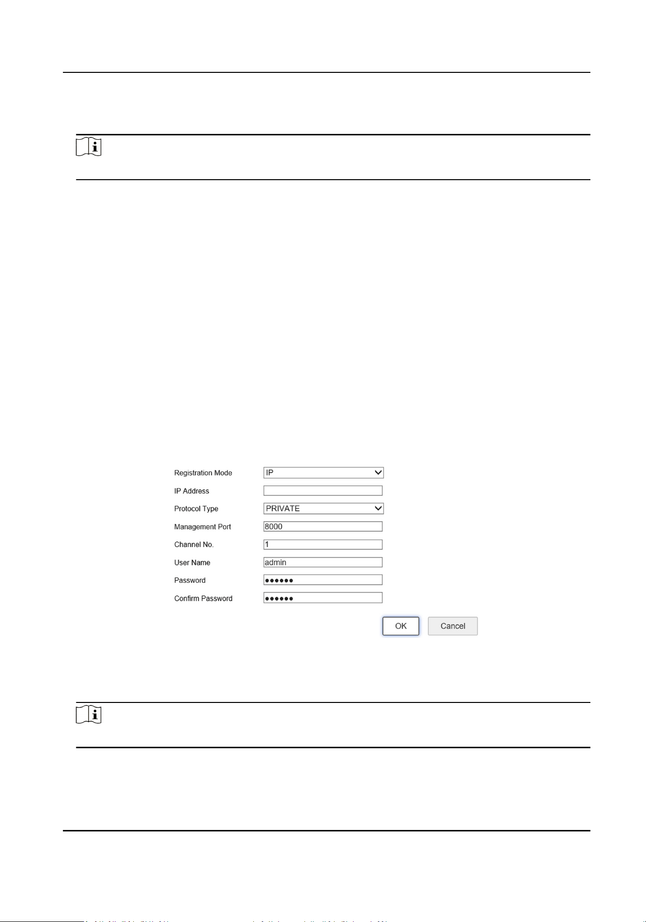
Manual Add
Add manually if you need to customize the access protocol or port.
Before You Start
Connect the device to the camera via the network interface.
Steps
1.
Go to Param Cong → System → Camera Management → IP Camera .
2.
Click Add.
Figure 3-5 Manual Add
3.
Select Registraon Mode.
4.
Select Protocol Type of the added camera.
Note
The device and the camera should both support the selected protocol type.
5.
Enter the camera IP address/domain name, port, user name, password, and other informaon.
Terminal Server User Manual
9

Note
Channel No. is only used to select the access channel when mulple channel devices are
accessed. For example, if you want to access the Channel 5 device, you can choose Channel 2 as
a network camera to access, then enter 2 at Channel No..
6.
Click OK.
7.
Oponal: You can also do the following operaons.
Edit Edit the added camera IP address.
Delete Delete the added camera.
Reboot Reboot the online camera.
Access Directly Access the online camera.
3.3.2 Set Interacon Parameters
Set interacon parameters to control the interacon data between the camera and the device.
Before You Start
Add the camera.
Steps
1.
Go to Param Cong → System → Camera Management → Interacve Sengs .
2.
Select a camera.
3.
Select an
interacon mode.
-
Normal Mode: In this mode, you can know the camera status via the camera's stream, and
you can record and preview images and receive image data via the server.
-
Data Receiving Mode: In this mode, you can only receive image data via the server, but you
cannot record or preview the images.
4.
Click Save.
3.4 Set Remote Host
Set remote host when the device needs to transmit data to the central control plaorm.
Before You Start
Set the remote host, and ensure the device can communicate normally with the remote host.
Steps
1.
Go to Param
Cong → Plaorm Sengs → Remote Host .
2.
Select a remote host.
Terminal Server User Manual
10

Note
The supported number of remote hosts varies with dierent devices. The actual interface
prevails.
3.
Select Plaorm Access Mode according to the actual communicaon protocol.
-
Remote Host: select this mode when communicang via remote host protocol.
-
Hp Host: select this mode when communicang via HTTP protocol.
4.
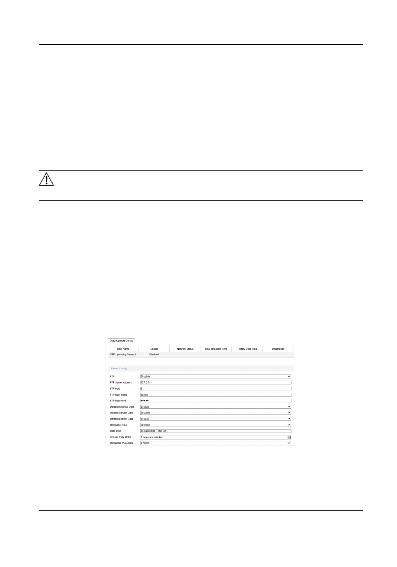
Set access parameters.
1) For access via the remote host, please select Upload Protocol. For access via
Hp host, please
enter URL and select Address Type.
2) Enter host IP address and port.
5.
Click the enter box behind Data Type to check the upload data type and select
specic upload
data.
Note
For access via the remote host, Upload Strategy needs to be set rst. Parameters may be
dierent under dierent protocols. The actual interface prevails.
6.
Select the License Plate Color.
7.
Set the upload types to be enabled (for example, Upload History Data, Upload No-Plate Data,
Upload Blocklist Data, Upload Allowlist Data, and Upload by Time) according to your needs,
and set other parameters.
Interval
The interval between 2 data uploads.
Timeout
When the upload
me of a single piece of data exceeds the set me, the data will be
automacally saved as history data and uploaded according to history data rule.
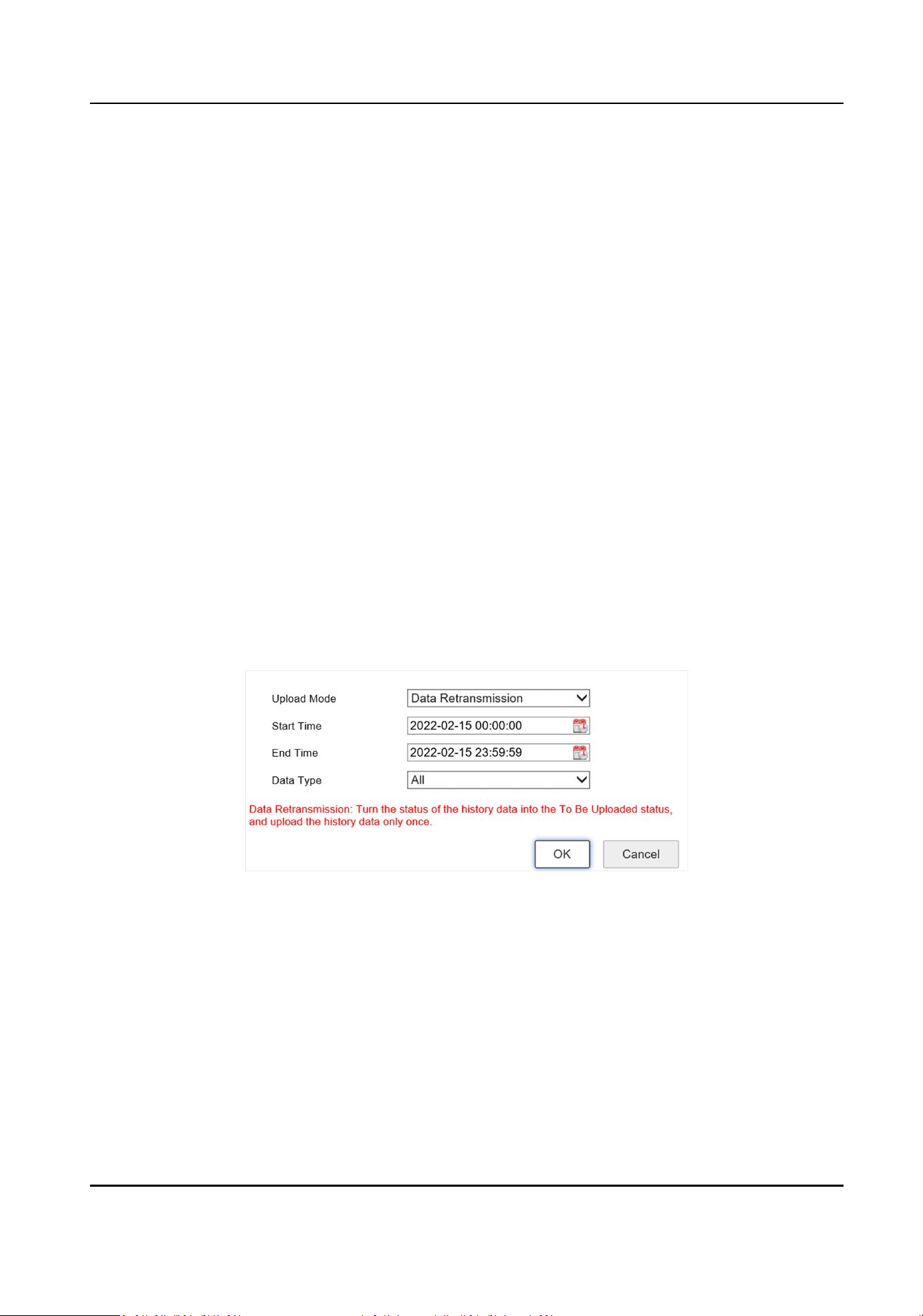
8.
Click Data Upload Cong.
1) Select Upload Mode, Start Time, End Time, and Data Type.
2) Click OK.
9.
Oponal: Check Enable Cloud Storage to set the picture server ID, and upload the remote host
data to the cloud.
Note
Only certain devices in specic protocol support cloud storage sengs. The actual interface
prevails.
10.
Oponal: Repeat the above steps if you need to set another remote host.
11.
Click Save.
Terminal Server User Manual
11

Chapter 4 Event Detecon and Face Recognion
4.1 Set Vehicle Arming
The device supports seng vehicle arming to manage special license plates.
Steps
1.
Go to Param Cong → Advanced Sengs → Vehicle Arming → Arming Management .
2.
Check Blocklist Arming or Allowlist Arming.
3.
Oponal: Check Blocklist Time Period Arm or Allowlist Time Period Arm to set specic arming
me periods.
Note
Aer checking these two funcons, you can set the arming me period while adding an item,
and the arming will be performed within the set me period. Otherwise, the arming will be
performed all day long.
Example
If you check Blocklist Time Period Arming and set the arming
me period between 8 AM and 9
AM, the arming would be performed between the set me period. If you don't check Blocklist
Time Period Arming, the arming would be performed all day long by default even though you
set the
me period while adding the item.
4.
Add arming data.
Batch Import
a. Download the import template and ll in relevant informaon.
b. Click Import to select the le with the relevant informaon.
c. Click Import.
Manually Add a. Select Arming Type.
b. Click Add.
c. Enter License Plate Number, and set the specic date and me.
d. Click OK.
5.
Oponal: You can also do the following operaons.
Search Data
Click Search aer selecng the arming type or entering the license plate
number to view relevant data.
Edit Data Check the item to be edited and click Edit to edit this item.
Delete Data Check the item to be deleted and click Delete to delete this item.
Export Data Check the item to be exported and click Export to export the item to the
designated path.
Terminal Server User Manual
12
4.2 Set Event Parameters
4.2.1 Set Camera Parameters
You can set camera parameters for easy management.
Steps
1.
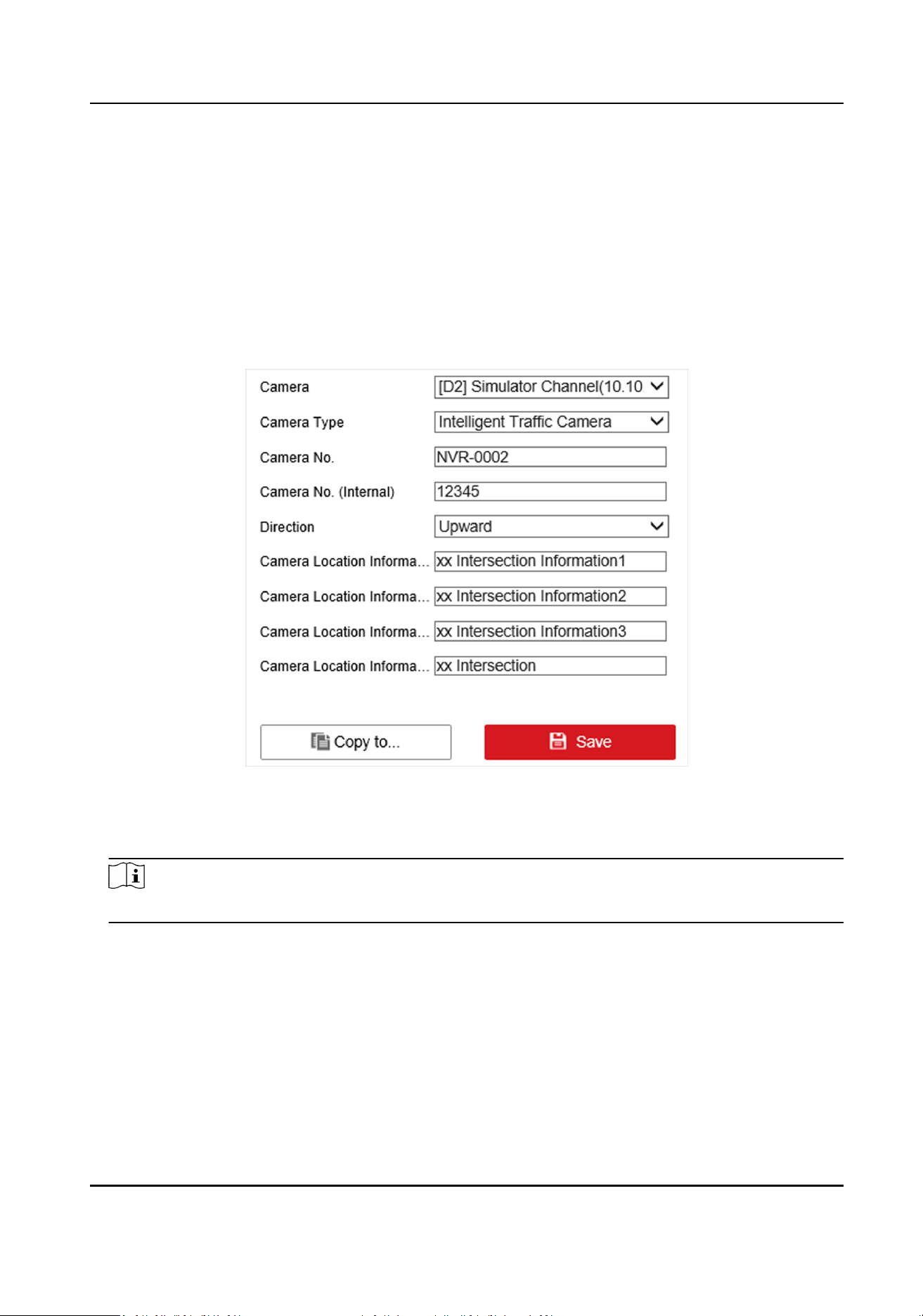
Go to Param Cong → System → Camera Management → Camera Parameter .
Figure 4-1 Set Camera Parameters
2.
Select a camera.
3.
Select Camera Type.
Note
The camera types vary with dierent models. The actual device prevails.
●
Camera for Video Surveillance: Terminal server won't receive capture pictures.
●
Intelligent
Trac Camera: Terminal server will receive capture pictures.
4.
Set Camera No., Camera No. (Internal), and Camera Locaon Informaon.
5.
Select
Direcon according to the vehicle passing direcon.
6.
Oponal: Click Copy to... to copy the sengs to other channels.
7.
Click Save.
Terminal Server User Manual
13

4.2.2 Set Violaon Diconary
Violaon diconary denes corresponding codes of violaon types, and it is convenient for
violaon recognion.
Steps
1.
Go to Param Cong → Diconary Sengs .
2.
Select a violaon type.
3.
Check the data and click Edit to edit the code.
4.
Oponal: You can also do the following operaons.
Add Click Add to add custom acts and codes.
Delete Check the added data and click Delete to delete the data.
Note
The default data in the diconary cannot be deleted.
Reset Click Reset to restore the diconary to the factory sengs, and all the custom data
will be cleared.
Terminal Server User Manual
14

Chapter 5 Data Management
5.1 View Real-Time Data
The device supports viewing captured violaon informaon in real me.
Steps
1.
Click Real-Time Data.
2.
View the data.
View the vehicle violaon
detailed informaon
Check the data row, and the le side of the interface will
display the vehicle violaon detailed informaon.
View the vehicle violaon
picture informaon
Click Picture to view the vehicle violaon picture
informaon.
5.2 Search Data
You can search the trac data of the connected cameras by searching data.
Steps
1.
Click Data Search → Trac Data Search .
2.
Set Start Time and End Time.
Note
The me span between the start me and the end me cannot exceed 7 days.
3.
Set the search condions.
4.
Click Search.
The searched result will be displayed.
5.
Click Details
aer the data to view detailed informaon, pictures, video clips, etc.
6.
Oponal: Aer the data has been searched, click Export to export the selected data informaon
to the set path.
Note
Make sure the IP of the camera has been added as a trusted site before exporng the data.
5.3 Enable Trac Parameters Stascs
Aer enabling the trac parameters stascs, the device will receive and store the trac stascs
of the camera.
Terminal Server User Manual
15

Steps
1.
Go to Param Cong → Advanced Sengs → Other Sengs → Trac Parameters Stascs .
2.
Check Trac Parameter Stascs.
3.
Click Save.
5.4 View Trac Stascs
You can view the trac stascs of the specic me period via data search.
Steps
1.
Go to Data Search → Trac Parameters Stascs .
2.
Set Start Time and End Time.
3.
Select
Stascs Cycle according to the actual needs.
4.
Select a camera.
5.
Click
Stascs.
6.
Oponal: Aer the data has been searched, click Export to export the selected data informaon
to the set path.
5.5 Back up Data
5.5.1 Back up to Local
You can back up the data of the device to your computer.
Before You Start
Search the data to back up.
Steps
1.
Set the data export rule.
1) Go to Param Cong → Backup Sengs → Web Backup .
2) Enter the name, saving path, and other
informaon of the picture and video.
Note
Aer the random number digits have been set, pictures with the same name will be
automacally numbered. The upper limit of the number is the maximum number of the
random number digits.
3) Click Save.
2.
Set the device IP address as a trusted site in the security sengs of the browser.
3.
Search the data, refer to
Search Data for details.
4.
Click Export to select export type and export the data to your computer.
Terminal Server User Manual
16

Result
Data will be backed up as the set name in the set path.
5.5.2 Back up to USB
The device supports automacally backing up the data to the USB.
Before You Start
Connect a USB to the device.
Steps
1.
Go to Param
Cong → Backup Sengs → Local Backup → USB Backup Sengs .
2.
Click USB Backup Sengs.
3.
Enable USB backup.
4.
Select Backup Period and Start Time.
-
Real-Time Backup: Automacally back up the data only once aer the data have been saved
at the set
me.
-
Backup Every Day: Automacally back up the data once a day at the set me.
5.
Select Data Type to backup.
6.
Enter the picture backup naming rule and saving path.
7.
Click Save.
Pictures will be backed up with the set name in the set path.
8.
Oponal: Click USB Backup Status to view the backup status.
Terminal Server User Manual
17

Chapter 6 Live View and Local Conguraon
6.1 Live View
6.1.1 Start/Stop Live View
Start/stop the live view of cameras.
Start Live View
Click the camera list on the le side of the live view interface to start a camera live view.
Note
If you want to display a camera live view in a specic split window, please select the split window
rst, and then click the camera to start live view. The display window is only set for once, and you
need to set it again when you start live view next me.
Click to start all live view.
Stop Live View
When the camera starts live view, click the camera list on the le side of the live view interface to
stop live view.
Click
to stop all live view.
6.1.2 Divide Window and Switch Page
Select window division if you need to switch the single or mul-window live view mode, and view
the camera live view of all pages via switching the page.
Divide Window
Click to select the live view window division mode according to the actual needs.
Switch Page
When the number of divided windows is less than the cameras, click and to switch page and
view the camera live view of all pages.
6.1.3 Select Stream Type
The device supports the dual-stream technology, including a main stream and a sub-stream. The
main stream stands for a high-resoluon and high bit rate stream, mainly used for storing
Terminal Server User Manual
18

recordings. The sub-stream stands for a low-resoluon and low bit rate stream, mainly used for
bandwidth-saving network transmission.
Click / in the channel list to select the stream type.
6.1.4 Capture Manually
Capture live view pictures and save them to your computer.
Steps
1.
Click Live View.
2.
Double click the channel name on the le to enable live view.
3.
Click .
4.
Name and save the captured pictures.
Note
Go to Param Cong → Local to view the saving path of snapshots in live view.
6.1.5 Record Manually
You can record videos manually on the live view image and save them to the computer.
Steps
1.
Click to start live view.
2.
Click
to start recording.
3.
Click to stop recording.
4.
Oponal: Go to Param Cong → Local to view the saving path of record les.
6.1.6 Enable/Disable Audio
Enable the audio if necessary aer relevant conguraon of a connected audio input device.
Click
to enable and adjust the audio. Click the icon again to mute the audio.
6.1.7 Enable Digital Zoom
You can enable digital zoom to zoom in a certain part of the live view image.
Steps
1.
Click to start live view.
2.
Click
to enable digital zoom.
3.
Place the cursor on the live view image posion which needs to be zoomed in. Drag the mouse
rightwards and downwards to draw an area.
The area will be zoomed in.
Terminal Server User Manual
19
4.
Click any posion of the image to restore to normal image.
5.
Click to disable digital zoom.
6.1.8 Display in Full Screen
You can display the live view image in full screen.
On Live View interface, click to display the live view image in full screen.
Press esc on the keyboard to exit the full screen mode.
6.2 PTZ Control
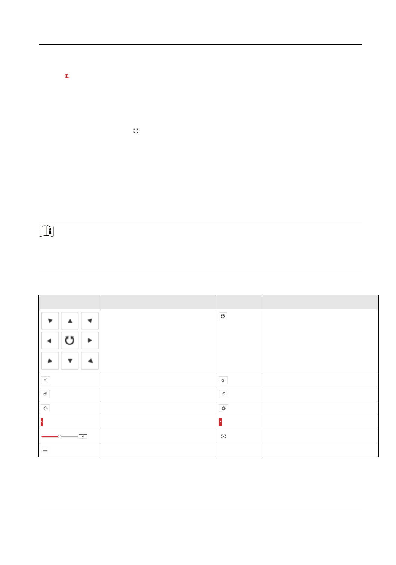
6.2.1 PTZ Control Panel
Click Live View and control PTZ cameras via PTZ control panel.
Note
●
PTZ control panels may vary with recorder models. The actual device prevails.
●
PTZ device supports power-down memory. Aer PTZ device suddenly loses power or reboots, it
can automacally go back to the former posion.
Table 6-1 Buons Descripon
Icon Descripon Icon Descripon
Direcon buons Auto-scan buon
Zoom - Zoom +
Focus + Focus -
Iris + Iris -
Display the PTZ control panel Hide the PTZ control panel
Control the PTZ speed Auxiliary focus
Menu / /
Terminal Server User Manual
20
Note
Other funcons are reserved.
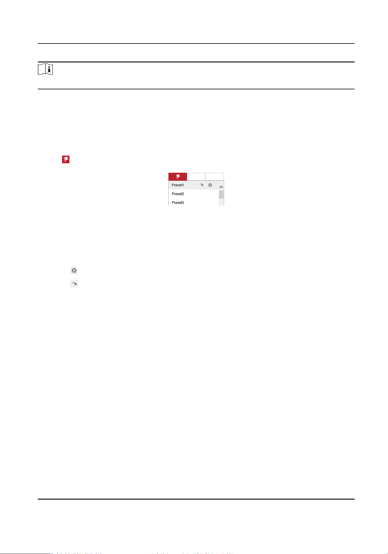
6.2.2 Set Preset
A preset is a predened image posion. For the dened preset, you can call the preset No. to view
the posion.
Steps
1.
Click .
Figure 6-1 Set Preset
2.
Operate the direcon buons of PTZ control to adjust PTZ to the desired posion, and adjust the
focus, zoom, etc., to get the desired scene.
3.
Select the preset to set.
4.
Oponal: You can also do the following operaons.
Click
Set preset according to prompt.
Click Call the preset, then PTZ will turn to the set direcon.
6.3 Local Conguraon
Go to Param Cong → Local to set the live view parameters.
Terminal Server User Manual
21
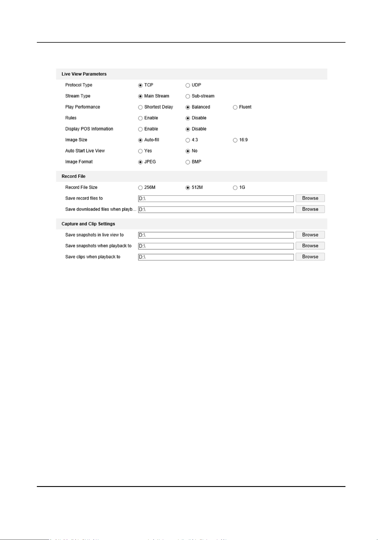
Figure 6-2 Local Conguraon
Protocol Type
TCP
Ensures completely delivery of streaming data and beer video quality, yet the real-me
transmission will be aected.
UDP
Provides
real-me audio and video streams.
Stream Type
The stream type decides the denion of live view image.
Main Stream
Provides the best resoluon and frame rate the device can do.
Sub-stream
Provides comparavely low resoluon opons.
Play Performance
Shortest Delay
The video is real-me, but the video uency may be aected.
Terminal Server User Manual
22

Balanced
Balanced mode considers both the real me and uency of the video.
Fluent
When the network condion is good, the video is uent.
Rules
If you select Enable, set rule informaon will be displayed on the live view interface.
Display POS Informaon
If you select Enable, the POS informaon of the capture camera will be displayed on the live
view interface.
Image Size
Select according to your needs.
Auto Start Live View
If you select Yes, you can view the camera live view image
aer login the browser. If you select
No, you need to start live view manually aer login the device.
Image Format
Set the saving format of captured pictures.
JPEG
The picture will be compressed.
BMP
The picture will not be compressed.
Record File Size
Select the packed size of the manually recorded video les. Aer the selecon, the max. record
le size is the value you selected.
Save record les to
Set the saving path for the manually recorded video les in live view interface.
Save downloaded les when playback to
Set the saving path for the downloaded les in playback mode.
Save snapshots in live view to
Set the saving path of the manually captured pictures in live view mode.
Save snapshots when playback to
Set the saving path for the manually captured pictures in playback mode.
Save clips when playback to
Set the saving path for the clips in playback mode.
Terminal Server User Manual
23
Chapter 7 Network Conguraon
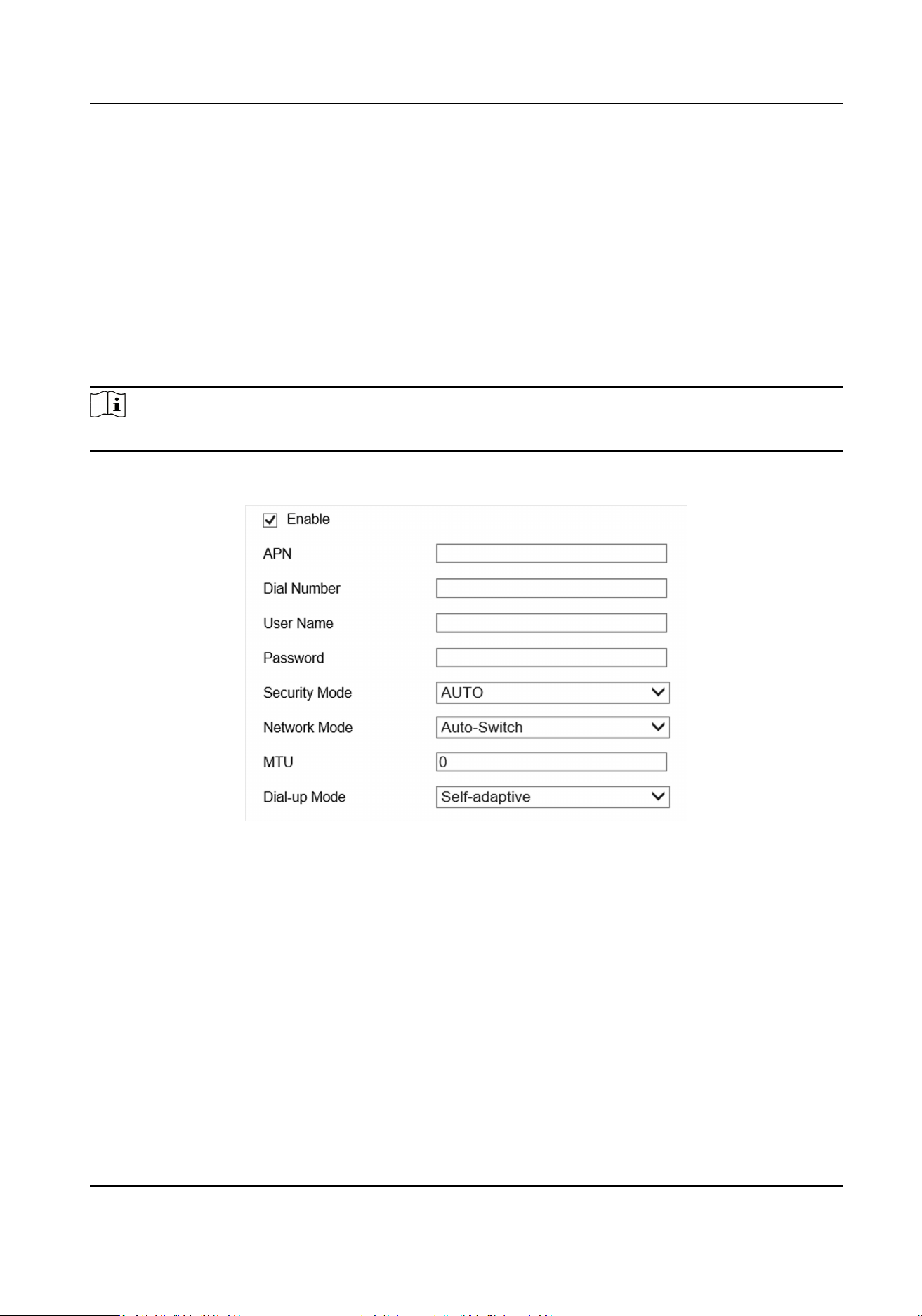
7.1 Dial
Set the dial-up parameters if you want to connect the device to the network via a SIM card.
Before You Start
The device has a dial-up module and a SIM card has been installed.
Steps
Note
This funcon varies with dierent models. The actual device prevails.
1.
Go to Param Cong → Network-Advanced Sengs → Wireless Communicaon Conguraon .
Figure 7-1 Set Dial-up Parameters
2.
Check Enable.
3.
Set dial-up parameters.
-
When you connect the device to the private network, set the dial number, user name,
password and APN informaon according to the SIM card informaon.
-
When you connect the device to the normal network, you do not need to set the dial-up
parameters.
4.
Select Security Mode and Network Mode according to the actual needs.
Auto-Switch
The device will switch the network mode
automacally aer connected to the Internet.
3G Only/4G Only
Terminal Server User Manual
24
Connecng the device via 3G/4G.
5.
Set MTU.
Note
The MTU is the maximum payload length for a parcular transmission media.
6.
Select Dial-up Mode according to the actual needs.
7.
Click Save.
8.
Oponal: You can go to Param Cong → System Status → Server Status → Wireless Network
Status to view results.
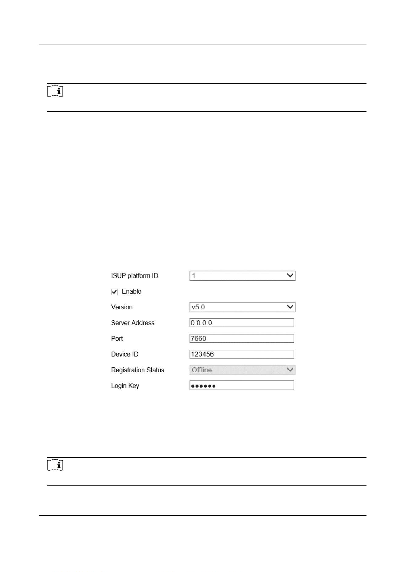
7.2 Connect to ISUP Plaorm
ISUP (EHome) is a plaorm access protocol. The device can be remotely accessed via this plaorm.
Before You Start
●
Create the device ID on ISUP
plaorm.
●
Ensure the device can communicate with the plaorm normally.
Steps
1.
Go to Param Cong → Network → Advanced Sengs → ISUP .
Figure 7-2 Connect to ISUP Plaorm
2.
Select ISUP plaorm ID.
3.
Check Enable.
4.
Select Version.
5.
Enter Server Address, Port, and Device ID.
Note
The device ID should be the same with the added one on the ISUP plaorm.
Terminal Server User Manual
25
6.
Oponal: Enter Login Key if you select v5.0.
7.
Click Save.
8.
Oponal: View Registraon Status.
Note
When the registraon status is online, you can add or manage the device via the plaorm
soware. Refer to its corresponding manual for details.
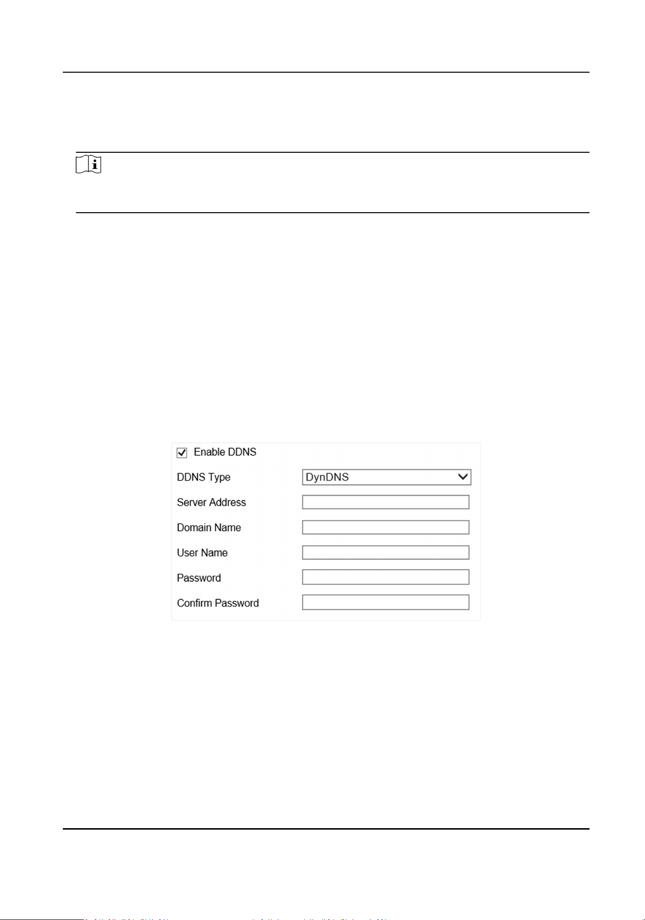
7.3 Set DDNS
You can use the Dynamic DNS (DDNS) for network access. The dynamic IP address of the device can
be mapped to a domain name resoluon server to realize the network access via domain name.
Before You Start
●
Register the domain name on the DDNS server.
●
Set the LAN IP address, subnet mask, gateway, and DNS server parameters. Refer to "Set IP
Address" for details.
●
Complete port mapping. The default ports are 80, 8000, and 554.
Steps
1.
Go to Param Cong → Network → Basic Sengs → DDNS .
Figure 7-3 Set DDNS
2.
Check Enable DDNS.
3.
Enter the server address and other informaon.
4.
Click Save.
What to do next
Enter the domain name in the browser address bar to access the device.
Terminal Server User Manual
26

7.4 Set Port
The device port can be modied when the device cannot access the network due to port conicts.
Cauon
Do not modify the default port parameters at will, otherwise the device may be inaccessible.
Go to Param
Cong → Network → Basic Sengs → Port for port sengs. Click Save aer nishing
sengs.
HTTP Port
It refers to the port through which the browser accesses the device. For example, when the
HTTP Port is modied to 81, you need to enter hp://192.168.1.64:81 in the browser for login.
RTSP Port
It refers to the port of real-me streaming protocol.
HTTPS Port
It refers to the port of encrypted transmission and identy authencaon protocol.
Server Port
It refers to the port to connect to client for obtain network protocol control and set device
parameters.
Note
●
Certain ports need to reboot aer edited to take the new sengs into eect.
●
When the device cannot edit the port No. via access Web due to port conicts, you can connect
the device to your computer and edit via SADP soware.
7.5 Set SNMP
Set the SNMP to obtain or receive excepons or alarms that occur during the transmission.
Before You Start
Deploy the SNMP server and make sure corresponding parameters are set. Make sure the server
can work normally.
Steps
1.
Go to Param
Cong → Network → Advanced Sengs → SNMP .
Terminal Server User Manual
27
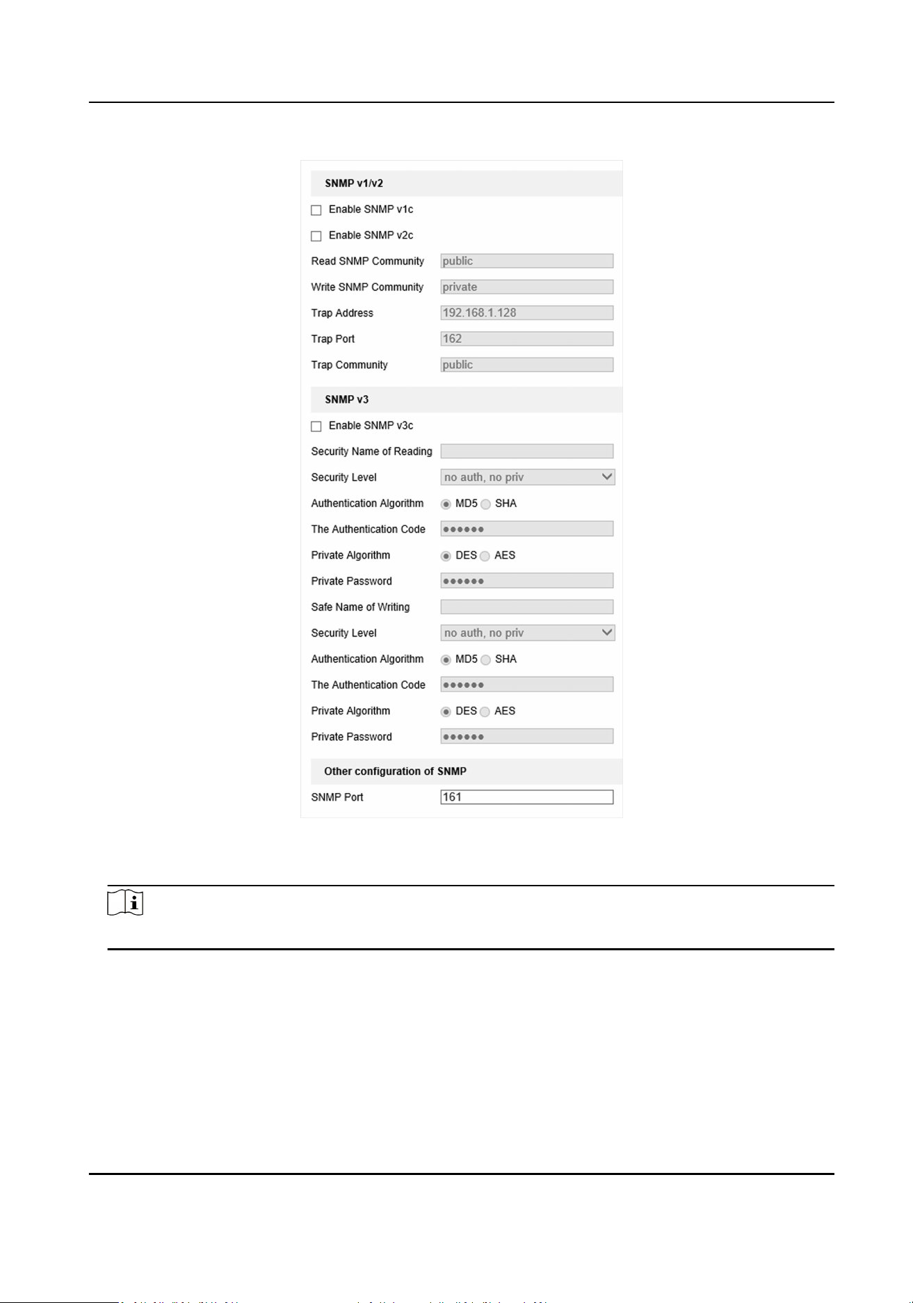
Figure 7-4 Set SNMP
2.
Check the SNMP version according to the protocol version of the SNMP server.
Note
It is recommended to use SNMP v3 in order to enhance the security level.
3.
Click Save.
7.6 Set ONVIF
If you want to use the device as an ONVIF server, you should enable this funcon.
Terminal Server User Manual
28

Steps
1.
Go to Param Cong → Network → Advanced Sengs-Integraon Protocol .
2.
Enable ONVIF.
3.
Click Save.
Terminal Server User Manual
29
Chapter 8 Record and Playback
8.1 Set Storage Path
8.1.1 Format Disk
Format the disk when the storage is abnormal or a new disk is installed.
Steps
Cauon
Formang the disk will cause the disk data loss. Back up the data rst.
1.
Go to Param Cong → Storage → Storage Management → HDD Management .
2.
Check the HDD No. needs to be
formaed.
3.
Click Format.
8.1.2 Set FTP
Set FTP parameters if you want to upload the captured pictures or recordings to the FTP server.
Before You Start
Set the FTP server, and ensure the device can communicate normally with the server.
Steps
1.
Go to Param Cong → Plaorm Sengs → FTP Upload .
Figure 8-1 Set FTP
2.
Select a FTP server.
3.
Set FTP parameters.
Terminal Server User Manual
30
1) Enable the FTP.
2) Enter FTP Server Address, FTP Port, FTP User Name, and FTP Password.
4.
Set upload parameters.
Upload Historical Data
Historical data refers to the data failed to be uploaded due to network disconnecon or
congeson. Aer this funcon has been enabled, historical data will be uploaded again.
Upload Allowlist Data
Upload the informaon of vehicles that are set in the allowlist through Param Cong →
Advance Sengs → Vehicle Arming .
Upload Blocklist Data
Upload the informaon of vehicles that are set in the blocklist through Param Cong →
Advance
Sengs → Vehicle Arming .
Upload by Time
Aer this funcon has been enabled, data will be uploaded within the me period between
the set uploading start me and the set uploading end me.
Upload No-Plate Data
Upload data of vehicles without license plates to the FTP server.
5.
Select License Plate Color and Data Type.
6.
Edit other relevant parameters according to the actual needs.
7.
Click Data Upload
Sengs to set relevant parameters.
Figure 8-2 Set Data Upload
1) Select Upload Mode.
Data Retransmission
Turn the status of the history data into the To Be Uploaded status, and upload the history
data only once.
History Data Priority
Upload the history data in the To Be Uploaded
rst.
Disable
Terminal Server User Manual
31
Turn the status of the history data into the Not to Be Uploaded status, and do not upload
these data.
2) Select Start Time and End Time.
3) Select the uploading data type in Data Type dropdown list.
4) Click OK.
8.
Oponal: Repeat the above steps to set another FTP.
9.
Click Save.
8.1.3 Set Cloud Storage
Cloud storage is a kind of network storage. It can be used as the extended storage to save the
captured pictures.
Before You Start
Arrange the cloud storage server.
Steps
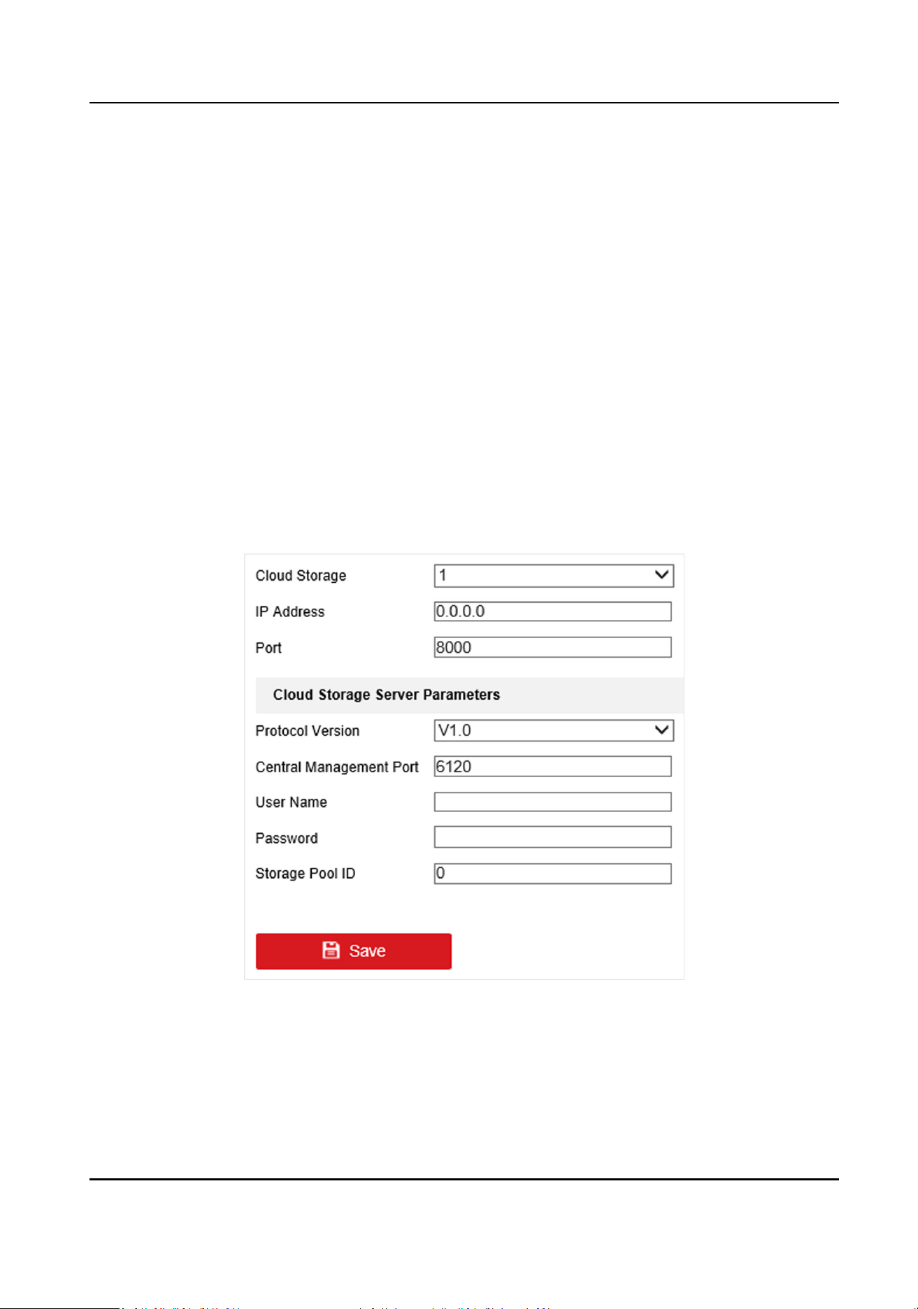
1.
Go to Param
Cong → Network → Advanced Sengs → Cloud Storage .
Figure 8-3 Set Cloud Storage
2.
Select Cloud Storage.
3.
Enter IP Address and Port of the cloud storage server.
4.
Set cloud storage server parameters.
Terminal Server User Manual
32

Protocol Version
Protocol version of the cloud storage server.
Note
The cloud storage server parameters vary with dierent protocol versions. The actual
interface prevails.
Central Management Port
Central management HTTP port of the cloud storage server.
Storage Pool ID
Storage pool ID of uploaded les on the cloud storage server.
User Name and Password
User name and password of the cloud storage server.
access_key
Key to access the cloud storage server.
secret_key
Key to encrypt the data uploaded to the cloud storage server.
5.
Click Save.
8.2 Set Quota
Set the picture rao in the storage.
Steps
1.
Go to Param Cong → Storage → Storage Management → Picture Quota .
2.
Set the capacity for saving picture according to the actual needs.
3.
Click Save.
8.3 Record
8.3.1 Set Timing Record
Set ming record if you need the camera to record automacally according to the set schedule.
Before You Start
Install and format the storage media (like HDD).
Steps
1.
Go to Param
Cong → Storage → Schedule Sengs → Recording Schedule .
Terminal Server User Manual
33
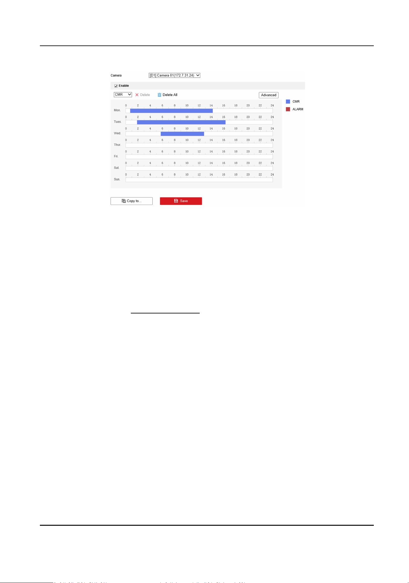
Figure 8-4 Set Timing Record
2.
Select camera.
3.
Check Enable, and select record type as CMR.
4.
Oponal: Click Advanced to set the camera record parameters.
-
Pre-record Time: The
me you set to start recording before the scheduled me.
-
Post-record: The me you set to stop recording aer the scheduled me.
-
Video Expiry Date: Automacally delete video les aer the scheduled me. 0 means that
video
les won't be deleted, but will be automacally overwrien aer enabled overwrien
record.
5.
Set record
me, refer to Set Record Schedule for details.
6.
Oponal: Click Copy to..., check the camera, and click OK.
7.
Click Save to save the
sengs.
8.3.2 Set Event Record
Set event record if you need the camera to record when event occurs.
Before You Start
●
Install and format the storage media.
●
Refer to event chapter for details of event
sengs.
Steps
1.
Go to Param
Cong → Storage → Schedule Sengs → Recording Schedule .
Terminal Server User Manual
34
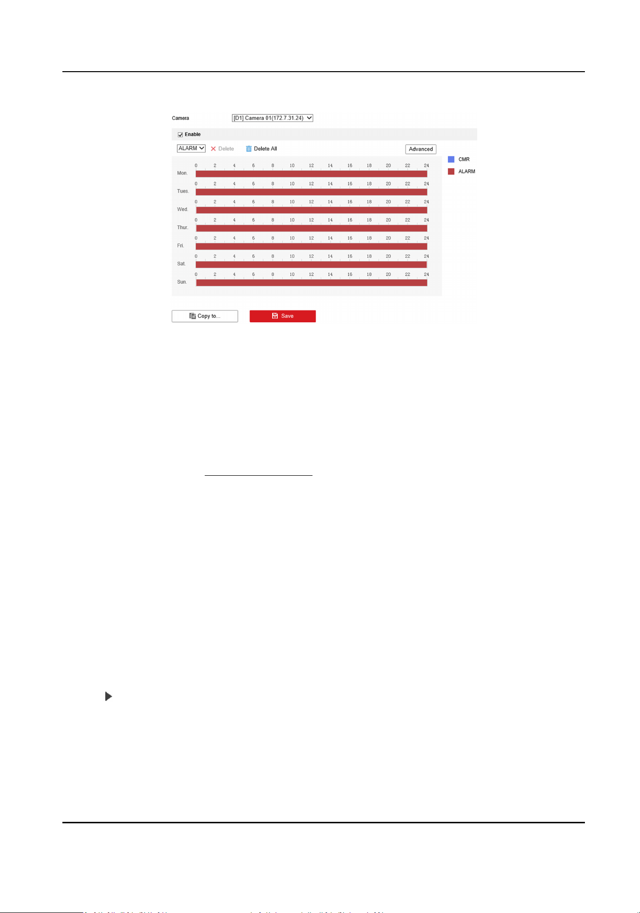
Figure 8-5 Set Event Record
2.
Select camera.
3.
Check Enable, and select record type as Alarm.
4.
Oponal: Click Advanced to set pre-record, post-record, video expiry date and stream type.
-
Pre-record Time: The me you set to start recording before the event.
-
Post-record: The
me you set to stop recording aer the event.
-
Video Expiry Date: Automacally delete video les aer the event. 0 means that video les
won't be deleted, but will be automacally overwrien aer enabled overwrien record.
5.
Set record
me, refer to Set Record Schedule for details.
6.
Oponal: Click Copy to..., check the camera, and click OK.
7.
Click Save to save the
sengs.
8.4 Play Back Video
You can play back the record les saved in the storage media (HDD, etc.).
Steps
1.
Click Playback.
2.
Select a camera.
3.
Select the
le date, and click Search.
-
Drag
me bar and put the yellow line at the me point that you need.
-
Enter the
specic me at Set Playback Time.
4.
Click
to play back the le.
5.
Oponal: You can also do the following operaons.
Terminal Server User Manual
35

Pause Start playback for selected
camera.
Split the playback window, and
play back mulple cameras
simultaneously.
Stop playback for selected
camera.
Fast forward. Slow forward.
Stop playback for all cameras. Capture pictures.
Reversed. Enable/disable audio.
Full screen. - -
Note
●
For the captured picture of playback saving path, refer to Save snapshots when playback to in
Param Cong → Local .
●
Operaons and buons vary with dierent models. The actual device prevails.
8.5 Backup
8.5.1 Back up Video
Download videos to a local path.
Steps
1.
Click Playback.
2.
Click .
3.
Select Camera.
4.
Select download type.
-
If you need to search video by date, select Download by Date, and select the date.
-
If you need to search video by le type, select Download by File, and select le type and
search
me.
5.
Select File Type.
6.
Click Search.
7.
Check videos to download and click Download.
8.
For the video saving path, refer to Save downloaded
les when playback to in Param Cong →
Local .
8.5.2 Back up Clipped Video
Clip videos and save them to a local path.
Terminal Server User Manual
36

Steps
1.
Click Playback.
2.
Select a camera and date.
3.
Click Search.
4.
Play the video.
5.
Drag
me bar to the clip start me and click to start clipping.
6.
Drag me bar to the clip end me and click to stop clipping.
7.
Go to Param Cong → Local to view the saving path of video clips.
Terminal Server User Manual
37

Chapter 9 Encoding and Display
9.1 Set Video Encoding Parameters
Set video encoding parameters to adjust the live view and recording eect.
●
When the network signal is good and the speed is fast, you can set high resoluon and bitrate to
raise the image quality.
●
When the network signal is bad and the speed is slow, you can set low resoluon, bitrate, and
frame rate to guarantee the image uency.
●
When the network signal is bad, but the resoluon should be guaranteed, you can set low
bitrate and frame rate to guarantee the image uency.
●
Main stream stands for the best stream performance the device supports. It usually oers the
best resoluon and frame rate the device can do. But high resoluon and frame rate usually
means larger storage space and higher bandwidth requirements in transmission. Sub-stream
usually
oers comparavely low resoluon opons, which consumes less bandwidth and storage
space. Third stream is oered for customized usage.
Steps
1.
Go to Param Cong → Video & Audio → Video .
2.
Select a camera.
3.
Set the parameters for
dierent streams.
Stream Type
Main stream stands for the best stream performance the device supports. It usually
oers the
best resoluon and frame rate the device can do. But high resoluon and frame rate usually
means larger storage space and higher bandwidth requirements in transmission. Sub-stream
usually
oers comparavely low resoluon opons, which consumes less bandwidth and
storage space.
Video Type
Select the video type to video & audio when you need taping while recording. Select video
when you only need record.
Note
The device only supports audio can select video & audio. The actual device prevails.
Resoluon
The higher the resoluon is, the clearer the image will be. Meanwhile, the network
bandwidth requirement is higher.
Bitrate Type and Max. Bitrate
Terminal Server User Manual
38

Select the bitrate type to constant or variable. Constant bitrate means that the stream is
compressed and transmied at a comparavely xed bitrate. Variable bitrate means that the
device automacally adjust the bitrate under the set Max. Bitrate.
Image Quality
When bitrate type is variable, you can select video quality according to actual needs. The
higher the video quality is, the higher requirements of the network bandwidth.
Frame Rate
It is to describe the frequency at which the video stream is updated and it is measured by
frames per second (fps). A higher frame rate is advantageous when there is movement in the
video stream, as it maintains image quality throughout.
Video Encoding
The device supports
mulple video encoding types. Supported encoding types for dierent
stream types may dier. H.265 is a new encoding technology. Compared with H.264, it
reduces the transmission bitrate under the same resoluon, frame rate, and image quality.
4.
Oponal: Click Copy to to copy the sengs to other channels.
5.
Click Save.
9.2 Set Image Parameters
Set image parameters to adjust brightness and contrast.
Steps
1.
Go to Param Cong → Image → Display Sengs .
2.
Select a camera.
3.
Set the parameters to obtain clear images.
Brightness
The brightness of the image.
Contrast
The contrast of the image. Set it to adjust the levels and permeability of the image.
Saturaon
The colorfulness of the image color.
Hue
Select the range to adapt to the display.
4.
Oponal: Click Restore Default Sengs to restore parameters to the default status.
9.3 Set OSD
You can customize OSD informaon on the live view.
Terminal Server User Manual
39

Steps
Note
The parameters vary with dierent models. The actual device prevails.
1.
Go to Param Cong → Image → OSD Sengs .
2.
Select a camera.
3.
Enter Camera Name, and select Time Format and Date Format.
4.
Check Display Name, Display Date, and Display Week according to actual needs.
5.
Oponal: Check the text overlay No. and enter contents according to your needs.
6.
Drag the red frame overlaid on the live view image to adjust the OSD informaon posions.
7.
Click Save.
Result
The set OSD will be displayed in live view image and recorded videos.
Terminal Server User Manual
40

Chapter 10 Alarm Congifuraon
10.1 Set Alarm Input
Alarm signal from the external device triggers the corresponding acons of the current device.
Before You Start
Make sure the external alarm device is connected. See Quick Start Guide for cable connecon.
Steps
1.
Go to Param Cong → Event → Basic Event → Alarm Input .
2.
Select Alarm Input No. and edit Alarm Name.
Note
If you select Alarm Input No. as A<-1(Cabinet Door Alarm) or A<-2(Cabinet Door Alarm)
(opons vary with dierent models), please go to Param Cong → Advanced Sengs → Other
Sengs to set Cabinet Door Name and Cabinet Door No..
3.
Select Alarm Type according to the alarm device type.
4.
Check Enable Alarm Input Handling.
5.
Refer to
Set Record Schedule for seng Arming Schedule.
6.
Refer to Set Linkage Mode for seng Linkage Acon.
7.
Oponal: Click Copy to... to copy the sengs to other alarm input channels.
8.
Click Save.
10.2 Set Alarm Output
Set alarm output to realize linkage alarm via external alarm device when the event occurs.
Before You Start
Make sure the external alarm device is connected. See Quick Start Guide for cable connecon.
Steps
1.
Go to Param
Cong → Event → Basic Event → Alarm Output .
Terminal Server User Manual
41
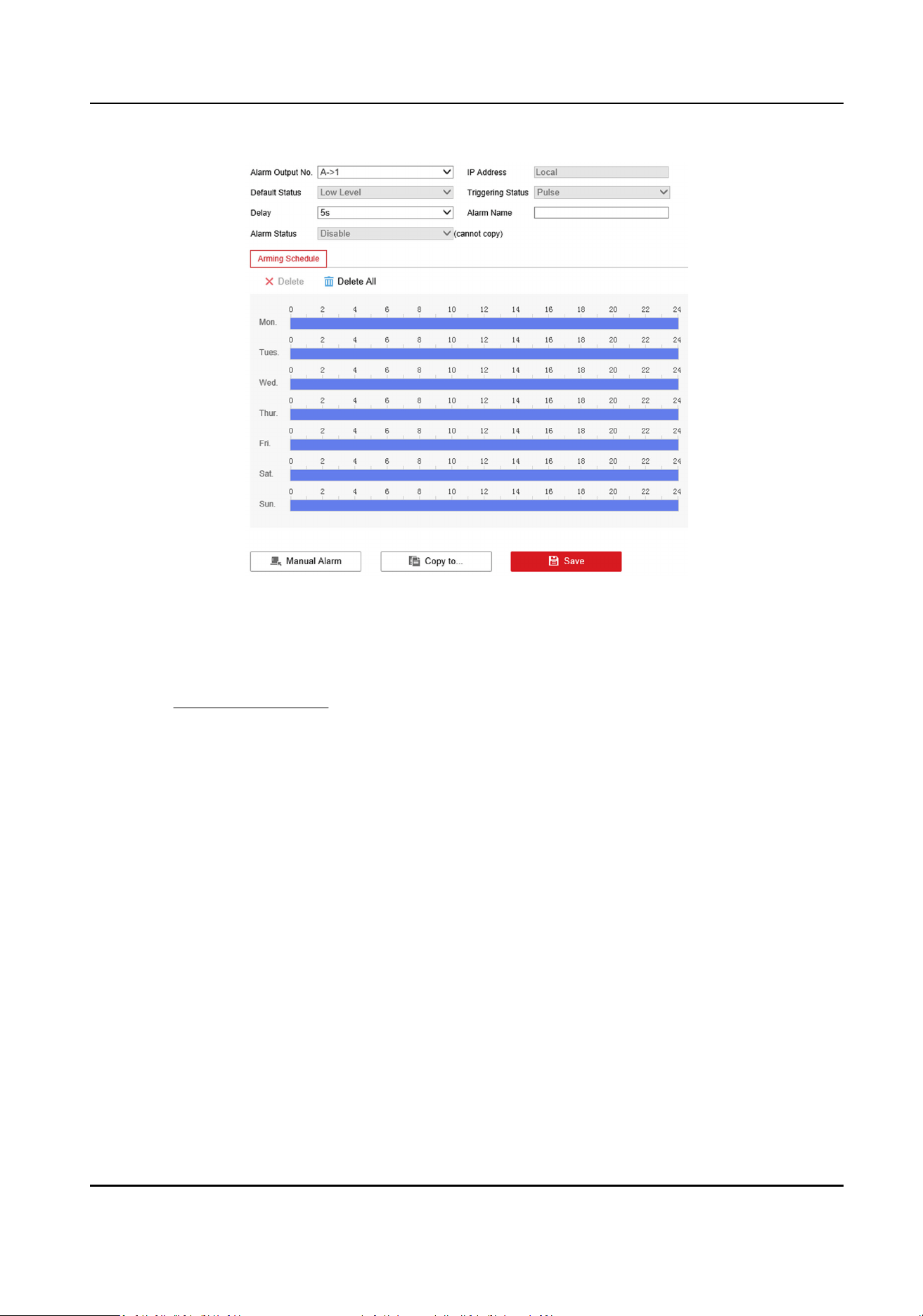
Figure 10-1 Set Alarm Output
2.
Select Alarm Output No. and edit Alarm Name.
3.
Select Delay.
The device will send out alarm output signal for the set
me.
4.
Refer to Set Record Schedule for seng Arming Schedule.
5.
Click Manual Alarm to enable manual alarm output. Set according to the actual needs.
6.
Oponal: Click Copy to... to copy the sengs to other alarm input channels.
7.
Click Save.
10.3 Set
Excepon Alarm
Set excepon alarm when the network is disconnected, the IP address is conicted, etc.
Steps
1.
Go to Param
Cong → Event → Basic Event → Excepon .
2.
Select Excepon Type.
HDD Full
The HDD storage is full.
HDD Error
Error occurs in HDD.
Network Cable Disconnected
Terminal Server User Manual
42

The device is oine.
IP Address conicted.
The IP address of current device is same as that of other device in the network.
Illegal Login
Incorrect user name or password is entered.
Record/Capture Excepon
Excepon occurs in record/capture.
Vehicle Blocklist
When vehicles in blocklist detected, alarm will be triggered.
Vehicle Allowlist
When vehicles in allowlist detected, alarm will be triggered.
3.
Refer to
Set Linkage Mode for seng linkage method.
4.
Click Save.
10.4 Set Record Schedule
Set the valid me of the device tasks.
Steps
1.
Click on the me bar and drag the mouse to select the me period.
2.
Adjust the me period.
-
Click on the selected me period, and enter the desired value. Click Save.
-
Click on the selected
me period. Drag the both ends to adjust the me period.
Note
●
Click Delete All to delete all the set schedules.
●
Up to 8 periods can be congured for one day.
3.
Oponal: You can also do the following operaons.
Copy the same
sengs
to other days
Move the mouse to the end of each day, a copy dialogue box pops
up, and you can copy the current sengs to other days.
Copy the same sengs
to other cameras
Click Copy to... to copy the same sengs to other days.
Note
This funcon varies with dierent devices. The actual interface
prevails.
4.
Click Save to save the sengs.
Terminal Server User Manual
43

10.5 Set Holiday
Set holiday for special days that alarms will not be triggered.
Steps
1.
Go to Param Cong → Storage → Advanced Sengs → Holiday .
Figure 10-2 Set Holiday
2.
Check the holiday date to set.
3.
Set the holiday parameters.
1) Click .
2) Set Holiday Name, Type, Start Date and End Date.
3) Click OK.
4.
Oponal: Repeat the previous step to set other holidays.
5.
Click Save.
10.6 Set Linkage Mode
Check the linkage acons as needed, and save the sengs.
Note
Available linkage modes may vary with dierent events. The actual interface prevails.
Nofy Surveillance Center
Upload the alarm informaon to the surveillance center.
Full Screen Monitoring
Display the image from the alarm channel in full screen.
Terminal Server User Manual
44
Chapter 11 Safety Management
11.1 Manage User
The administrator can add, modify, or delete other accounts, and grant dierent permissions to
dierent user levels.
Before You Start
Set the administrator password when you rst use the device to ensure a normal working.
Steps
Cauon
It is highly recommended to create a strong password of your own choosing in order to increase
the security of your product.
1.
Go to Param Cong → System → User Management .
2.
Click Add.
3.
Set the user name, password and other informaon in the popup window.
4.
Click OK.
5.
Oponal: You can also do the following operaons.
Delete the User
Select the added user and click Delete to delete the user.
Edit the User Informaon Select the added user and click Edit to edit the user informaon.
11.2 Install Authorized Cercate
If the demand for external access security is high, you can create and install authorized cercate
via HTTPS protocol to ensure the data transmission security.
Steps
1.
Go to Param Cong → Network → Advanced Sengs → HTTPS .
2.
Select Create the cercate request rst and connue the installaon. and click Create.
3.
Follow the prompt to enter Country/Region, Domain Name/IP, Password, and other
parameters.
4.
Click OK
5.
Click Download to download the
cercate request and submit it to the trusted authority for
signature.
Note
Cercaon of cercates issued by Cercaon Authority may incur costs.
6.
Import cercate to the device.
Terminal Server User Manual
45

-
Click Browse to select the cercate and click Setup to import the cercate to the device.
-
Select Signed cercate is available, start the installaon directly.. Click Browse to select the
cercate and click Setup to import the cercate to the device.
7.
Click Save.
11.3 Create and Install Self-signed Cercate
HTTPS is a network protocol that enables encrypted transmission and identy authencaon,
which improves the security of remote access.
Steps
1.
Go to Param Cong → Network → Advanced Sengs → HTTPS .
2.
Select Create Self-signed
Cercate.
3.
Click Create.
4.
Follow the prompt to enter Country/Region, Domain Name/IP, Eecve Period, and other
parameters.
5.
Click OK.
6.
Click Save.
11.4 Set SSH
To raise network security, disable SSH service. The conguraon is only used to debug the device
for the professionals.
Steps
1.
Go to Param
Cong → System → Security → Security Service .
2.
Uncheck Enable SSH.
3.
Click Save.
11.5 Set Session Expired Time
If you log out of the device or the device is disconnected, and then log in to the device within the
set session expired me, you will enter into the page which you logged out from the last me
automacally.
Steps
1.
Go to Param
Cong → System → Security → Security Enhancement .
2.
Enter Session Expired Time.
3.
Click Save.
Terminal Server User Manual
46

Chapter 12 Maintenance
12.1 View Device Informaon
Basic Informaon
Go to Param Cong → System → System Sengs → Basic Informaon to view the device basic
informaon.
You can edit Device Name and Device No. It is recommended to reserve the default value.
Device Status
Go to Param Cong → System Status to view the server status and other statuses.
12.2 Search Log
You can search logs to troubleshoot problems.
Steps
1.
Go to Param Cong → System → System Maintenance → Log Search .
2.
Set the search
condions.
3.
Click Search.
The log
informaon will be displayed in the list.
4.
Oponal: Click Export to export the logs to the computer.
12.3 Upgrade
Upgrade the system when you need to update the device version.
Before You Start
Prepare the upgrade le.
Steps
1.
Go to Param Cong → System → System Maintenance → Upgrade & Maintenance → Upgrade .
2.
Click Browse and select the upgrade
le.
3.
Click Upgrade.
4.
Click OK in the popup window.
Note
The upgrade process will take 1 to 10 minutes. Do not cut o the power supply.
Result
The device will reboot automacally aer upgrade.
Terminal Server User Manual
47

12.4 Reboot
When the device needs to be rebooted, reboot it via the soware instead of cung o the power
directly.
Steps
1.
Go to Param Cong → System → System Maintenance → Upgrade & Maintenance → Reboot .
2.
Click Reboot.
3.
Click OK to reboot the device.
Reboot
The device will reboot
automacally in every 2 a.m.
Reboot Without HDD
The device will reboot when no HDD is detected.
12.5 Restore Parameters
When the device is abnormal caused by the incorrect set parameters, you can restore the
parameters.
Steps
1.
Go to Param
Cong → System → System Maintenance → Upgrade & Maintenance → Restore
Default Sengs .
2.
Select the
restoraon mode.
-
Click Restore to restore the parameters except the IP parameters and
plaorm parameters to
the default
sengs.
-
Click Default to restore all the parameters to the factory sengs.
3.
Click OK.
12.6 Restore Database
When an excepon occurs, you can restore the database if you have backed up the database
before.
Before You Start
Make sure you have backed up the database before.
Steps
1.
Go to Param Cong → System → System Maintenance → Upgrade & Maintenance → Restore
Database .
2.
Click Restore.
3.
Click OK.
Terminal Server User Manual
48
12.7 Set RS-485
Set RS-485 parameters if the device has been connected to a vehicle detector or other RS-485
devices.
Before You Start
The corresponding device has been connected via the RS-485 serial port.
Steps
1.
Go to Param
Cong → System → System Sengs → Serial Port .
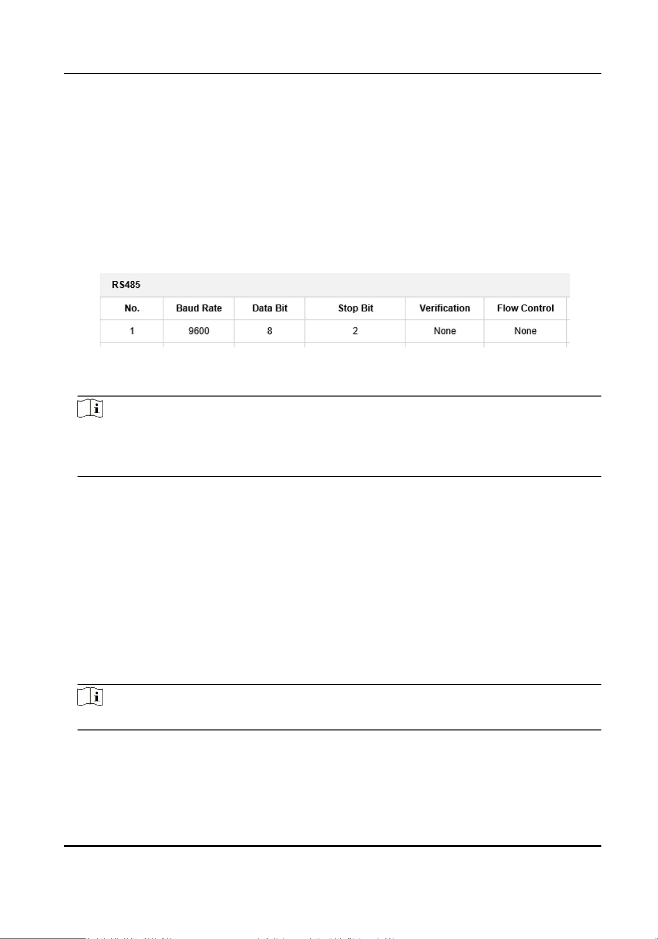
Figure 12-1 Set RS-485
2.
Set Baud Rate, Data Bit, Stop Bit, Vericaon and Flow Control.
Note
●
Flow control can control the process of data transmission and avoid data loss.
●
When you select hardware ow control, you need to ensure the cable connecon. It is
recommended to select soware ow control if the cable connecon is restricted.
3.
Click Save.
12.8 Set RS-232
Set RS-232 parameters if you need to debug the device via RS-232 serial port, or peripheral devices
have been connected.
Before You Start
The corresponding device has been connected via the RS-232 serial port.
Steps
1.
Go to Param
Cong → System → System Sengs → Serial Port .
2.
Select COM port according to the connected peripheral devices.
Note
Do not need to select COM port if the device only has one RS-232.
3.
Oponal: Edit Baud Rate, Data Bit and Stop Bit.
4.
Select Control Mode.
Transparent Channel
Terminal Server User Manual
49

For the data transmission of peripheral devices.
Control Panel(By Parameter)
For the serial port debugging of the device.
5.
Click Save.
12.9 Synchronize Camera Time
It is recommended to synchronize the camera
me when the camera me is inconsistent with the
device me.
Steps
1.
Go to Param Cong → Advanced Sengs → Other Sengs → Other Sengs .
2.
Select Camera Time
Synchronizaon as Enable.
3.
Set the interval.
4.
Click Save.
Result
The device will synchronize the camera me at the set interval to ensure its me is consistent with
the device
me.
12.10 Synchronize Time
Synchronize the device me when it is inconsistent with the actual me.
Steps
Note
Time sync. mode varies with dierent models. The actual interface prevails.
1.
Go to Param Cong → System → System Sengs → Time Sengs .
2.
Select Time Zone.
3.
Select the
me sync. mode.
NTP Time Sync.
Select it to synchronize the device me with that of the NTP server. Set Server Address, NTP
Port, and Interval. Click NTP Test to test if the
connecon between the device and the server
is normal.
Note
The me synchronizaon modes vary with dierent models. The actual device prevails.
Manual Time Sync.
Terminal Server User Manual
50

Select it to synchronize the device me with that of the computer. Set me manually, or
check Sync. with Computer Time.
GPS Time Sync.
Select it to synchronize the device me with that of the GPS. It is high-eciency and less
error.
SDK Time Sync.
If the remote host has been set for the device, select it to synchronize me via the remote
host.
EHome Time Sync
Select it to synchronize the device
me with that of the EHome plaorm.
4.
Click Save.
12.11 Set DST
If the region where the device is located adopts Daylight Saving Time (DST), you can set this
funcon.
Steps
1.
Go to Param Cong → System → System Sengs → DST .
2.
Check Enable DST.
3.
Set Start Time, End Time, and Bias Time.
4.
Click Save.
12.12 Export Parameters
You can export the parameters of one device, and import them to another device to set the two
devices with the same parameters.
Steps
1.
Go to Param Cong → System → System Maintenance → Upgrade & Maintenance → Export
Parameters .
2.
Click Device Parameters.
3.
Select the saving path and enter the
le name.
4.
Click Save.
12.13 Import Parameters
Import the conguraon le of another device to the current device to set the same parameters.
Before You Start
Save the le that needs to be imported to the computer.
Terminal Server User Manual
51

Steps
Note
Imporng conguraon le is only available to the devices of the same model and same version.
1.
Go to Param Cong → System → System Maintenance → Upgrade & Maintenance → Import
Parameters .
2.
Click Browse to import the
conguraon le.
3.
Click Import.
Result
The parameters will be imported, and the device will reboot.
12.14 Detect HDD
Detect HDD regularly to avoid data loss due to HDD damage.
Steps
1.
Go to Param Cong → Storage → Storage Management → HDD Detecon .
S.M.A.R.T.
Detecon Detect and report on various indicators of reliability in the hopes of
ancipang failures.
Bad Sector Test Detect the block capacity of the HDD.
2.
Select HDD No. and Self-test Type, and click Start Detecng.
Result
Decide whether to use the HDD any more according to the
detecon result. If there are too many
bad sectors, change the HDD in
me.
12.15 Set Working Mode
You can set the device under the listening mode or arming mode.
Before You Start
Ensure the connected camera supports violaon capture funcon.
Steps
Note
Trac Data Matching Strategy is a reserved funcon.
1.
Go to Param Cong → Advanced Sengs → Other Sengs → Other Sengs .
Terminal Server User Manual
52
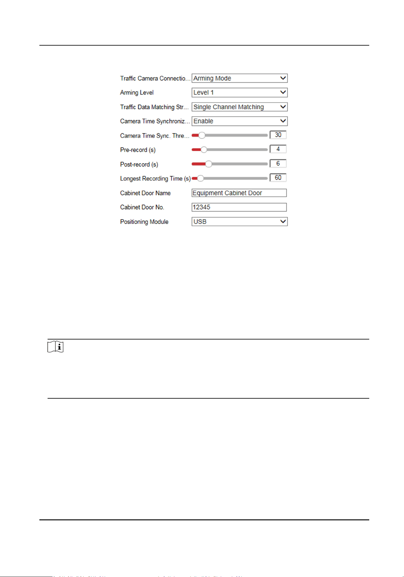
Figure 12-2 Set Working Mode
2.
Select Trac Camera Connecon Mode.
Arming Mode
The device
acvely connects to the camera and receives images aer logging in to the
camera.
Listening Mode
You need to connect the camera to the device. Aer set the camera under listening mode,
the device can receive the data uploaded from the camera.
3.
Select Arming Level.
Note
●
Level 1 arming can only connect 1 client or web. Level 2 arming can connect 3 clients or webs.
Level 3 arming can connect 5 clients or webs.
●
The device supports to set level 1, level 2 and level 3 arming simultaneously. The level 1
arming uploads
rst.
4.
Select Camera Time Synchronizaon.
5.
Set record
me parameters.
Pre-record
The me to record before the violaon recording start me.
Post-record
The me to record aer the violaon recording end me.
Longest Recording Time
The longest recording me of violaon recording.
Terminal Server User Manual
53

6.
Enter the name and No. of the cabinet door.
7.
Select Posioning Module according to the connected posioning module type of the device.
8.
Click Save.
9.
Oponal: Click Data Search and select search condions to search relevant violaon recordings.
12.16 Reserved Parameters
The reserved parameters are for technical personnel debugging only.
Terminal Server User Manual
54

Appendix A. Communicaon Matrix and Device
Command
Scan the QR code below to get the
communicaon matrix of the device.
Figure A-1 Communicaon Matrix
Scan the QR code below to get the device command.
Figure A-2 Device Command
Terminal Server User Manual
55

UD27597B
