
DS-TPM400 Guidance Terminal
User Manual

User Manual
COPYRIGHT ©2017 Hangzhou Hikvision Digital Technology Co., Ltd.
ALL RIGHTS RESERVED.
Any and all information, including, among others, wordings, pictures, graphs are the
properties of Hangzhou Hikvision Digital Technology Co., Ltd. or its subsidiaries
(hereinafter referred to be “Hikvision”). This user manual (hereinafter referred to be
“the Manual”) cannot be reproduced, changed, translated, or distributed, partially or
wholly, by any means, without the prior written permission of Hikvision. Unless
otherwise stipulated, Hikvision does not make any warranties, guarantees or
representations, express or implied, regarding to the Manual.
About this Manual
This Manual is applicable to DS-TPM400 Series Guidance Terminal.
The Manual includes instructions for using and managing the product. Pictures, charts,
images and all other information hereinafter are for description and explanation only.
The information contained in the Manual is subject to change, without notice, due to
firmware updates or other reasons. Please find the latest version in the company
website (http://overseas.hikvision.com/en/).
Please use this user manual under the guidance of professionals.
Trademarks Acknowledgement
and other Hikvision’s trademarks and logos are the properties of
Hikvision in various jurisdictions. Other trademarks and logos mentioned below are
the properties of their respective owners.
Legal Disclaimer
TO THE MAXIMUM EXTENT PERMITTED BY APPLICABLE LAW, THE
PRODUCT DESCRIBED, WITH ITS HARDWARE, SOFTWARE AND
FIRMWARE, IS PROVIDED “AS IS”, WITH ALL FAULTS AND ERRORS, AND
HIKVISION MAKES NO WARRANTIES, EXPRESS OR IMPLIED, INCLUDING
WITHOUT LIMITATION, MERCHANTABILITY, SATISFACTORY QUALITY,
FITNESS FOR A PARTICULAR PURPOSE, AND NON-INFRINGEMENT OF
THIRD PARTY. IN NO EVENT WILL HIKVISION, ITS DIRECTORS, OFFICERS,
EMPLOYEES, OR AGENTS BE LIABLE TO YOU FOR ANY SPECIAL,
CONSEQUENTIAL, INCIDENTAL, OR INDIRECT DAMAGES, INCLUDING,
AMONG OTHERS, DAMAGES FOR LOSS OF BUSINESS PROFITS, BUSINESS
INTERRUPTION, OR LOSS OF DATA OR DOCUMENTATION, IN
CONNECTION WITH THE USE OF THIS PRODUCT, EVEN IF HIKVISION HAS
BEEN ADVISED OF THE POSSIBILITY OF SUCH DAMAGES.
REGARDING TO THE PRODUCT WITH INTERNET ACCESS, THE USE OF
PRODUCT SHALL BE WHOLLY AT YOUR OWN RISKS. HIKVISION SHALL
NOT TAKE ANY RESPONSIBILITES FOR ABNORMAL OPERATION, PRIVACY
LEAKAGE OR OTHER DAMAGES RESULTING FROM CYBER ATTACK,
HACKER ATTACK, VIRUS INSPECTION, OR OTHER INTERNET SECURITY
RISKS; HOWEVER, HIKVISION WILL PROVIDE TIMELY TECHNICAL
SUPPORT IF REQUIRED.
SURVEILLANCE LAWS VARY BY JURISDICTION. PLEASE CHECK ALL
RELEVANT LAWS IN YOUR JURISDICTION BEFORE USING THIS PRODUCT
IN ORDER TO ENSURE THAT YOUR USE CONFORMS THE APPLICABLE
LAW. HIKVISION SHALL NOT BE LIABLE IN THE EVENT THAT THIS
PRODUCT IS USED WITH ILLEGITIMATE PURPOSES.
IN THE EVENT OF ANY CONFLICTS BETWEEN THIS MANUAL AND THE
APPLICABLE LAW, THE LATER PREVAILS.
Guidance Terminal User Manual
1
Symbol Conventions
The symbols that may be found in this document are defined as follows.
Symbol
Description
Provides additional information to emphasize or supplement
important points of the main text.
Indicates a potentially hazardous situation, which if not
avoided, could result in equipment damage, data loss,
performance degradation, or unexpected results.
Indicates a hazard with a high level of risk, which if not
avoided, will result in death or serious injury.
Safety Instructions
Please adopt the power adapter which can meet the safety extra low voltage
(SELV) standard.
To reduce the risk of fire or electrical shock, do not expose this product to rain or
moisture.
This installation should be made by a qualified service person and should
conform to all the local codes.
Please install blackouts equipment into the power supply circuit for convenient
supply interruption.
If the product does not work properly, please contact your dealer or the nearest
service center. Never attempt to disassemble the camera yourself. (We shall not
assume any responsibility for problems caused by unauthorized repair or
maintenance.)
Preventive and Cautionary Tips
Make sure the power supply voltage is correct before using the camera.
Do not drop the guidance machine or subject it to physical shock.
Do not place the camera in extremely hot, cold temperatures (please refer to the
product specification for the operating temperature), dusty or damp environment,
and do not expose it to high electromagnetic radiation.
To avoid heat accumulation, good ventilation is required for a proper operating
environment.
Keep the guidance terminal away from water and any liquid.
While shipping, the guidance terminal should be packed in its original packing.
Improper use or replacement of the battery may result in hazard of explosion.
Please use the manufacturer recommended battery type.
The additional equipment of PoE ports shall comply with requirement of fire
enclosure.

Guidance Terminal User Manual
2
Table of Contents
Chapter 1 Introduction ....................................................................................... 4
1.1 Description ...................................................................................................... 4
1.2 Features and Functions .................................................................................... 4
1.3 Application Scenario ........................................................................................ 5
Chapter 2 Installation ......................................................................................... 7
2.1 Structure Overview .......................................................................................... 7
2.1.1 Mainboard ........................................................................................................................ 7
2.1.2 Power Cord ....................................................................................................................... 8
2.2 Installation ...................................................................................................... 8
Chapter 3 Activation and Login ......................................................................... 12
3.1 Network Connection ...................................................................................... 12
3.2 Activation ...................................................................................................... 12
3.2.1 Activating via SADP ......................................................................................................... 13
3.2.2 Activating via Web Browser ............................................................................................ 15
3.3 Logging in via Web Browser ............................................................................ 16
Chapter 4 Configuration ................................................................................... 19
4.1 Local Configuration ........................................................................................ 19
4.2 Remote Configuration .................................................................................... 20
4.2.1 Configuring Device Parameters....................................................................................... 20
4.2.2 Managing Camera ........................................................................................................... 22
4.2.3 Configuring Camera ........................................................................................................ 26
4.2.4 Configuring Network ....................................................................................................... 35
4.2.5 Configuring Serial Port .................................................................................................... 38
4.2.6 Configuring Alarm ........................................................................................................... 39
4.2.7 Controlling Indicator ....................................................................................................... 42
4.2.8 Configuring Exception ..................................................................................................... 43
4.2.9 Managing User ................................................................................................................ 44
4.2.10 Managing HDD ................................................................................................................ 46
4.2.11 Running Log .................................................................................................................... 47
4.2.12 Maintenance ................................................................................................................... 47
4.2.13 Connecting to Platform ................................................................................................... 48
4.2.14 Configuring Remote Host ................................................................................................ 50
4.2.15 Viewing Status ................................................................................................................ 50
Chapter 5 Live View .......................................................................................... 52

Guidance Terminal User Manual
3
Chapter 6 Playback ........................................................................................... 54
6.1 Playback Interface .......................................................................................... 54
6.2 Searching Record Files .................................................................................... 55
Chapter 7 Log ................................................................................................... 56
7.1 Searching Log Files ......................................................................................... 56
Chapter 8 Data Search ...................................................................................... 58
Chapter 9 Status ................................................................................................ 59
Chapter 10 Statistics ........................................................................................ 61
10.1 Viewing Parking Space Information ................................................................ 61
10.2 Viewing LED Guidance Screen Information ..................................................... 62

Guidance Terminal User Manual
4
Chapter 1 Introduction
1.1 Description
DS-TPM400 series guidance terminal, based on the 4-core ARM Cortex-A17
processor, is a remarkable intelligent management system used for underground
garage. Adopting the advanced parking guidance and find my car system, the
guidance terminal is capable of connecting multiple parking cameras to realize
parking space detection, license plate recognition, guidance screen information
control, video storage, playback, etc.
The guidance terminal is widely used in the parking lot of the community, business
center and hotels. It greatly shortens the parking time and vehicle searching time of
customers, and improves the utilization of the spare parking spaces.
The models and description are shown in the following table.
Model
Description
DS-TPM400
Connectable to parking cameras via external power cord.
DS-TPM400-P
Supports PoE, and connectable to Hikvision PoE parking cameras
of the fourth generation.
1.2 Features and Functions
H.264 decoding to output the parking space detection and license plate
recognition algorithm results.
Connectable to guidance screen, displaying the available parking spaces no
matter it is online or offline.
Quick access to parking cameras, and batch configuration of parking cameras to
save the time cost of manual operation, monitor vehicles, and get event evidence
effectively.
Alternate indicator control. The parking camera can display the status of the
Guidance Terminal User Manual
5
12 VDC Power Cord
Network Cable
A6
A4A5 A3 A2
A1
A27
A29
A28A30
A31
A32
Guidance
Terminal
Parking
Camera
Parking
Camera
Figure 1-1 Application Scenario for DS-TPM400
opposite parking space.
Accessible
by
web
browser
and
integrated
SDK.
Accessible
to
platform
via
Ehome protocol, and Hik-Connect platform.
Dual NIC, which can connect to the internet and intranet and save IP resource.
Optical fiber access.
16
RJ45
network
interfaces,
connectable
to
up to
32
parking cameras.
Among the
16
network
interfaces,
8
interfaces
support
Hikvision
PoE
parking
cameras
connection.
Another
4
1000M
network interfaces are supported.
2 RS-485 serial ports to connect to the RS-485 control devices, such as guidance
screen.
Supports up to
18
TB
HDD storage.
1.3
Application
Scenario
Parking cameras can be connected to the guidance terminal via network to realize the
integrated
management,
video
search,
record,
playback,
etc.
Refer
to
the
following
figure for the
application
scenario of the guidance terminal.
Guidance Terminal User Manual
6
Network Cable
A6
A4A5 A3 A2
A1
A27
A29
A28A30
A31
A32
Guidance
Terminal
Parking
Camera
Parking
Camera
Figure 1-2 Application Scenario for DS-TPM400-P
Refer to User Manual of Parking Camera for the installation.
When PoE parking camera is connected to DS-TPM400-P guidance terminal, it
can be powered by the network cable directly.
Only the Hikvision PoE parking camera of the fourth generation can be
connected to the DS-TPM400-P guidance terminal.
Guidance Terminal User Manual
7
Chapter 2 Installation
2.1 Structure Overview
2.1.1 Mainboard
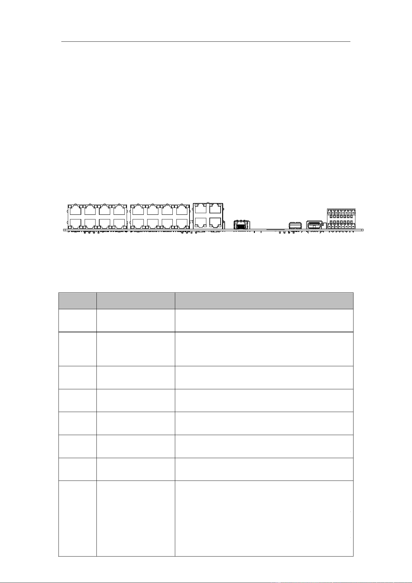
Refer to the following figure and table for the interfaces of the guidance terminal.
Parking cameras can be connected to the guidance terminal via corresponding
interfaces.
1 2 3
4
5
6
7
8
Figure 2-1 Interfaces
Table 1-1 Interfaces Description
No.
Name
Description
10/100M: Power &
Data
8 100M network interfaces, connecting to the
Hikvision PoE parking cameras.
10/100M
8 100M network interfaces for connecting to
parking cameras in hand-in-hand mode. They do
not support PoE.
10/100/1000M
4 1000M network interfaces for platform software
or PC access.
OPT
1 optical port. SFP optical module is needed for
network communication.
USB 3.0
1 USB 3.0
interface for connecting to mouse,
keyboard, USB flash drive, etc.
USB 2.0
1
USB 2.0 interfaces for connecting to mouse,
keyboard, USB flash dri
ve, etc.
7
RS 485 Interface
2 RS-485 interfaces.
8
ALARM IN/OUT
ch 2 larm
input.
larm . C1 and NO1 are a pair of relay
alarm output. F2+ and F3+ are I/O alarm outputs
ou can connect corresponding alarm input/output
devices according to needs.
2-ch alarm input. IN and G are a pair of alarm
input.
2-ch alarm output. C1 and NO1 are a pair of relay
alarm output. F2+ and F3+ are I/O alarm outputs.
You can connect corresponding alarm input/output
devices according to needs.
1
2
3
4
5
6
Guidance Terminal User Manual
8
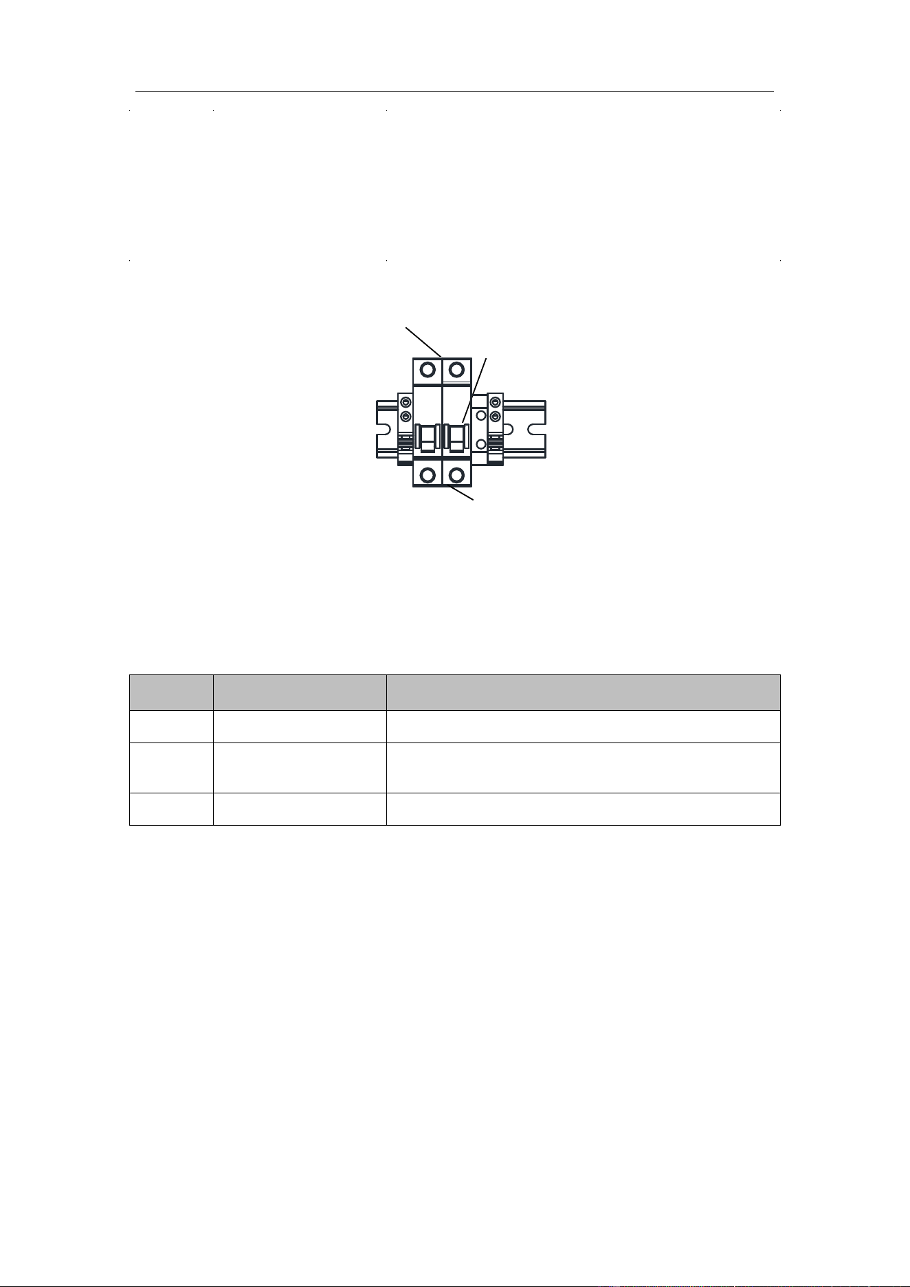
2.1.2 Power Cord
Refer to the following figure and table for the power cord description.
1
22
3
Figure 2-2 Power Cord
Table 1-2 Power Cord
No.
Name
Description
1
Power Output
220 VAC power output
2
Air Switch
1 air switch for controlling the circuit connected or
disconnected, and overcurrent protection.
3
Power Input
100 to 240 VAC power input
2.2 Installation
Before you start:
Check the installation environment.
Install the guidance terminal in the location where it is large enough to install the
expansion screws.
The installation location should bear at least 4 times of the weight of the guidance
terminal and accessory.
The installation location should be large enough to contain the guidance terminal
Guidance Terminal User Manual
9
and accessory.
Steps:
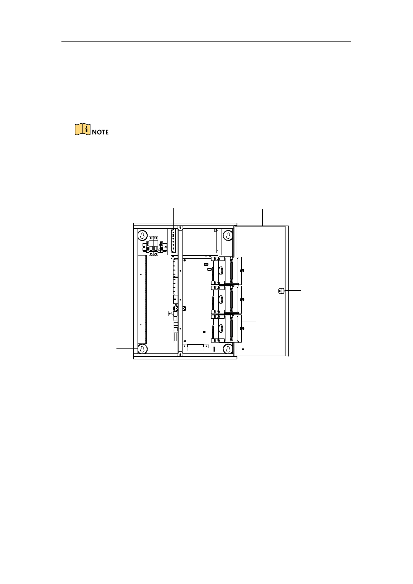
1. Rotate the key in the keyhole of the guidance terminal and open the cover of the
machine body.
If the guidance terminal supports PoE, it has 2 parts of power supply. The upper
part is used to provide power for cameras and terminal with 12 VDC. The lower
part is used to provide power for the PoE interfaces with 48 VDC.
Machine
Body
Cover
Power
Supply
Installation
Hole
Keyhole
HDD Slot
Figure 2-3 Open the Cover
2. Install HDD.
1) Loosen the set screws of the HDD and terminal, and lift the HDD slot to the
appropriate position.
2) Insert HDD to the slot, and fix it with 4 SC-CUNC6-32*5 screws.
3) Repeat step 1) and 2) to install other HDDs. Each HDD should be fixed with
4 screws.
4) Lay down the HDD slot, and use M3 screw to fix the screw hole. Tighten the
nut to fix the HDD slot to the terminal.
3. Drill 4 Ø8 screw holes on the wall according to the figure below and fasten the

Guidance Terminal User Manual
10
expansion screws into the drilled screw holes on the wall.
450
340
4-Ø 8
Unit:mm
Figure 2-4 Drill Screw Holes
4. Align the four installation holes on the machine body to the four expansion screws
on the wall to hook the terminal on the screws.
5. Connect network cable and power cord in the machine body, and route the cables
from the corresponding outlet holes according to the figure below.
Route the power cord from strong current outlet hole and other cables from
weak current outlet hole.
The weak current outlet hole is used for routing camera power cord, network
cable, etc.
The strong current outlet hole is used for routing the 220 VAC power cord.
Guidance Terminal User Manual
11
Top Weak Current
Outlet Hole
Side Weak Current
Outlet Hole
Top Strong Current
Outlet Hole
Side Strong Current
Outlet Hole
Figure 2-5 Wiring
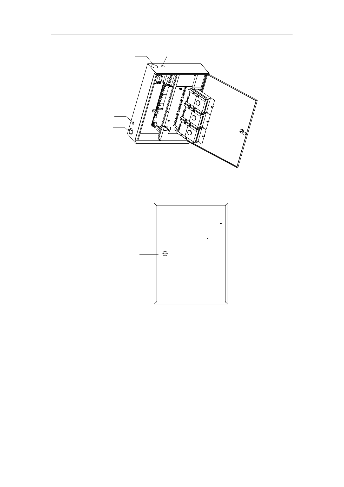
6. Close the cover and lock the key to finish the installation.
Keyhole
Figure 2-6 Lock the Key
Guidance Terminal User Manual
12
Chapter 3 Activation and Login
3.1 Network Connection
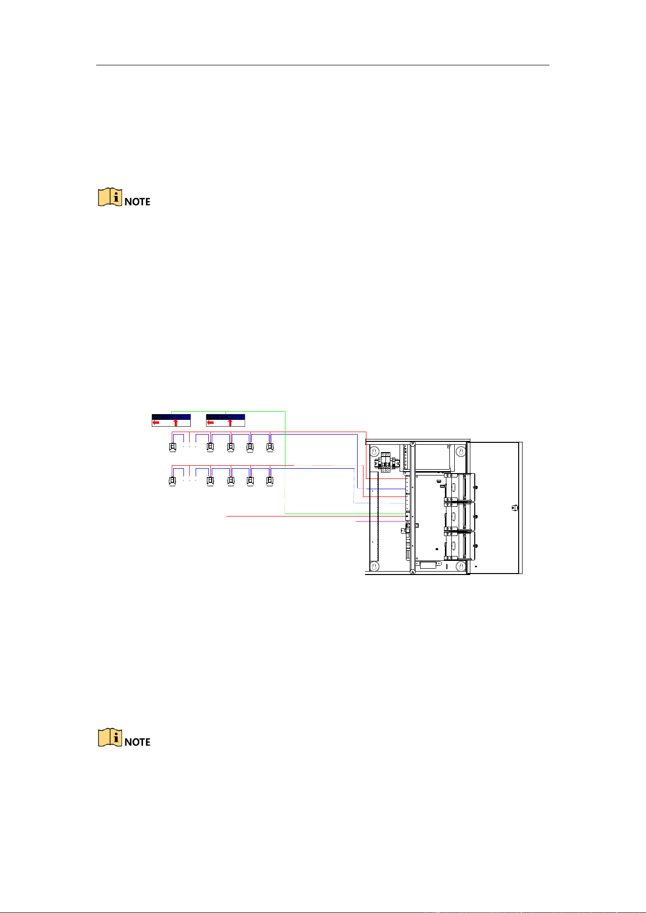
You shall acknowledge that the use of the product with Internet access might be under
network security risks. For avoidance of any network attacks and information leakage,
please strengthen your own protection. If the product does not work properly, please
contact with your dealer or the nearest service center.
Other devices including LED display units, parking cameras, control platforms, etc.
can be connected to the guidance terminal. The following figure takes an example of
the device connection for DS-TPM400.
1 2 3 4 5 6 1 2 3 4 5 6
Optical Fiber
Network Cable
Network Cable
Network
Cable
LED
Display
Units
Parking
Cameras
Network Cable
Power Cord
Power Cord
Connect to Guidance
System, Inquiry Terminal
and Notify Surveillance
Center
Figure 3-1 Device Connection
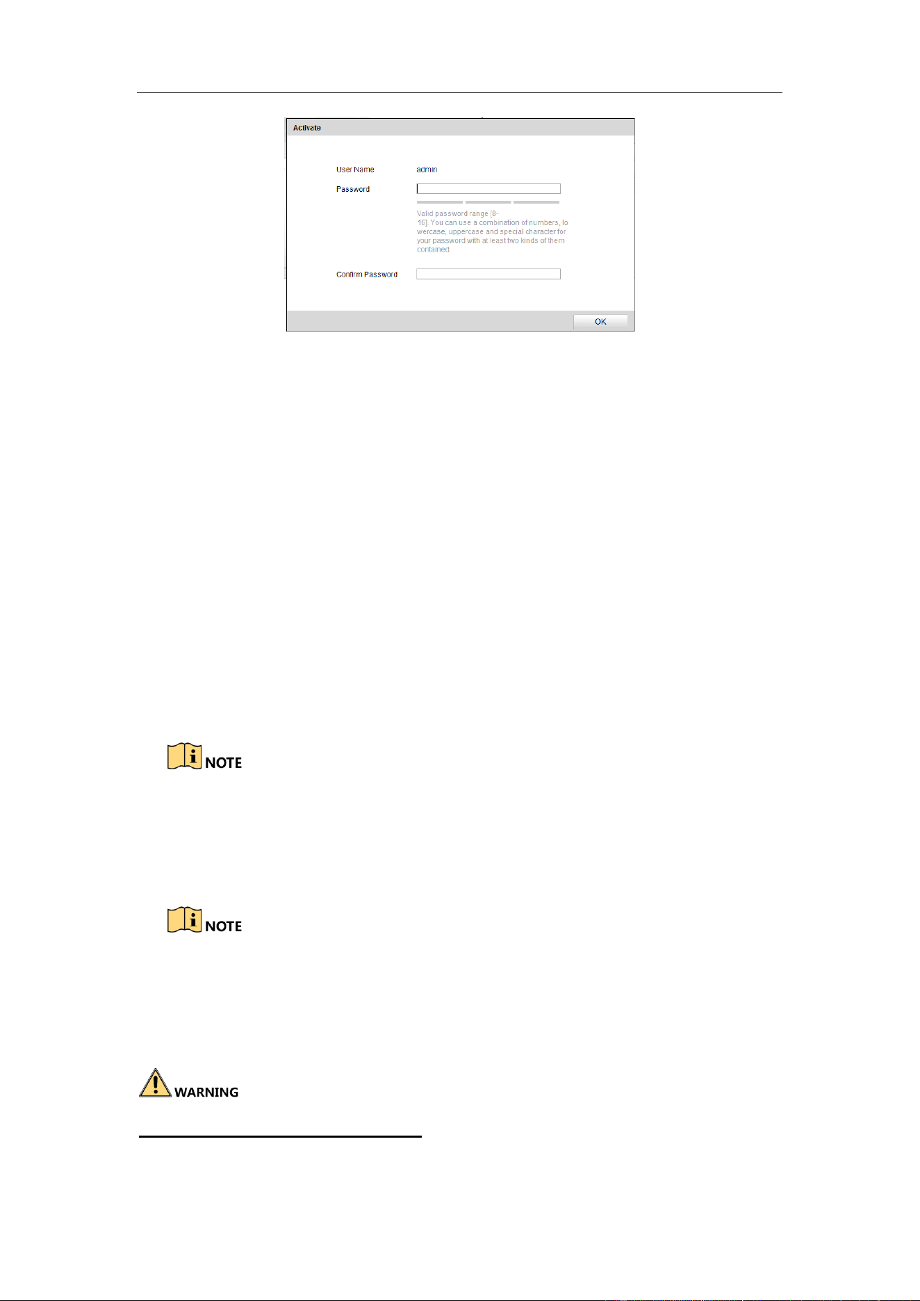
3.2 Activation
You need to active the device and set the password for first-time login. You can
activate the device through SADP or through web browser.
By default, the IP address of the guidance terminal
is 192.168.1.64.
The default port: 8000 port for SDK activation, 80 port for web browser
activation, and 37020 port for SADP activation.
Guidance Terminal User Manual
13
The default user account: admin.
3.2.1 Activating via SADP
SADP software is enclosed on the compact disc. You can also download it from the
company website.
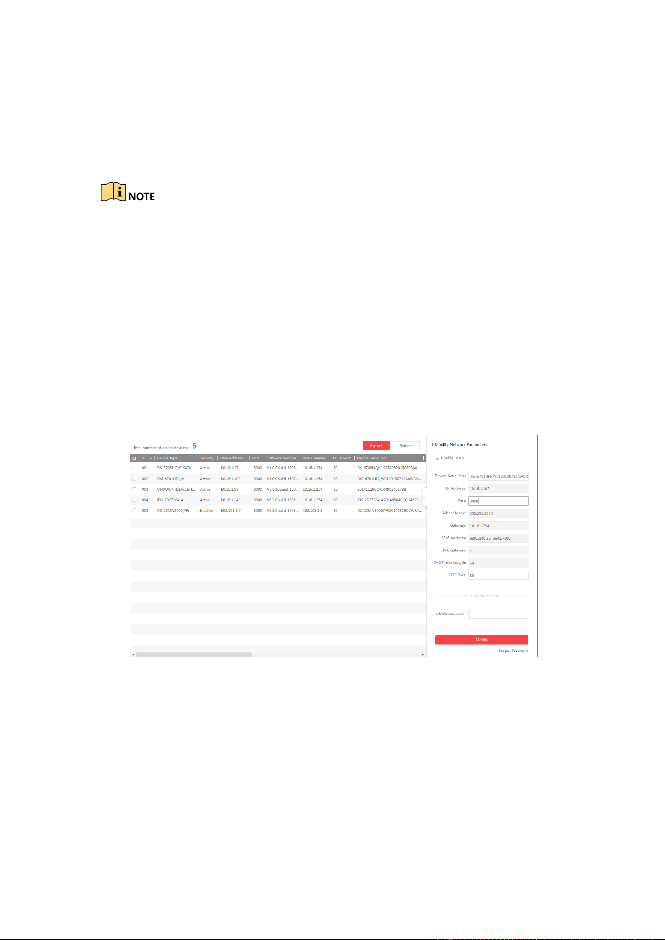
Steps:
1. Install SADP software. After launching the SADP software, it automatically
searches the online devices every 1 minute from the subnet where your computer
locates. It displays the total number and information of the searched devices in the
device list. Device information including the device type, IP address, port number,
gateway, etc. will be displayed as the figure below.
Figure 3-2 SADP Activation
2. Select the device which you need to activate by checking the checkbox and the
device information will be displayed in a list on the right side. In Activate the
Device panel, create a password for the device and confirm the password. The
system will judge password strength automatically, and we highly recommend you
to use a strong password to ensure your data security.
Guidance Terminal User Manual
14
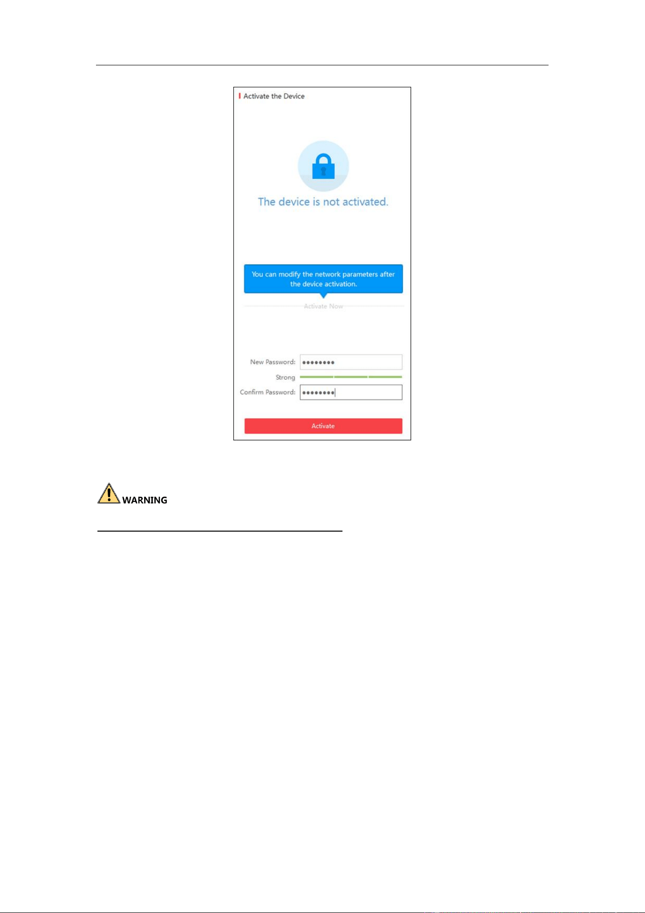
Figure 3-3 Create the Password
STRONG PASSWORD RECOMMENDED–A strong password ranges from 8 to
16 characters, and must contain at least two of the following categories: numbers,
lowercases, uppercases and special characters. And we recommend you reset your
password regularly, especially in the high security system, resetting the password
monthly or weekly can better protect your product.
3. Click Activate to activate the device. A “The device is activated.” hint window
pops up when the password is set successfully.
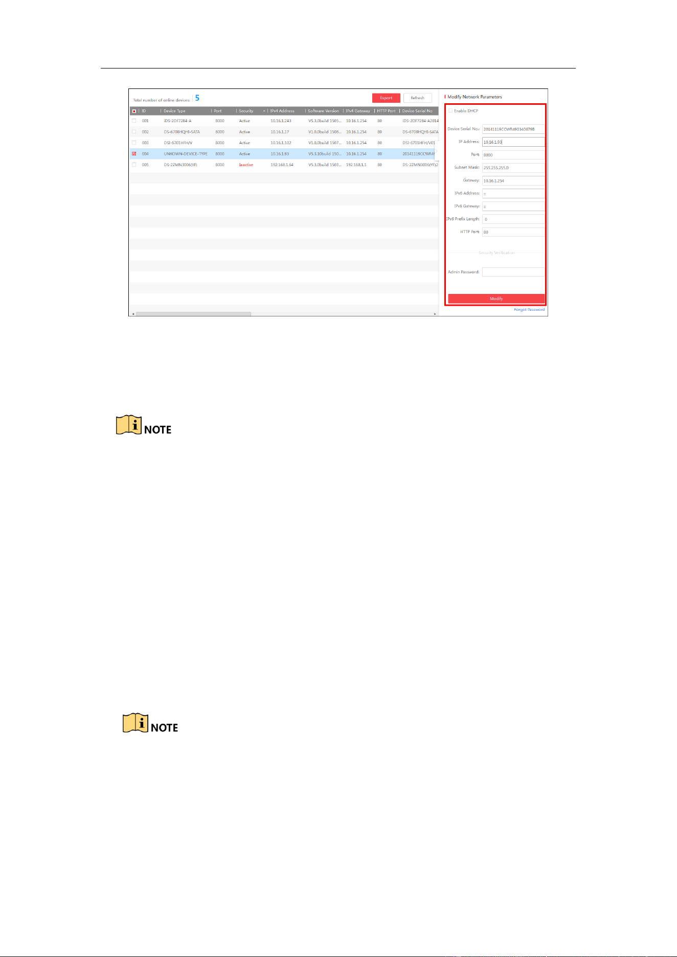
4. Modify the network parameters. Select the device to be modified in the device list
by checking the checkbox and the network parameters of the device will be
displayed in Modify Network Parameters panel on the right side. Set the
network parameters including IP address, sub network mask, gateway, etc.
Guidance Terminal User Manual
15
Figure 3-4 Modify the Parameters
5. Enter the password of the admin account of the device in the Admin Password
field and click Modify to modify the parameters.
When setting IP address, keep the device IP address and the computer IP
address in the same network segment.
“Admin” is device’s administrator user. We recommend you to create a new
user to operate for protecting your data security.
3.2.2 Activating via Web Browser
Steps:
1. Modify the IP address of your computer to ensure the computer IP address and the
device IP address are in the same network segment.
The default IP address of the guidance terminal is 192.0.0.64.
2. Input the default IP address of the guidance terminal in the address bar of the web
browser and the activation interface pops up. Enter a new password and click OK
to activate the device as the figure below.
Guidance Terminal User Manual
16
Figure 3-5 Activate through Web Browser
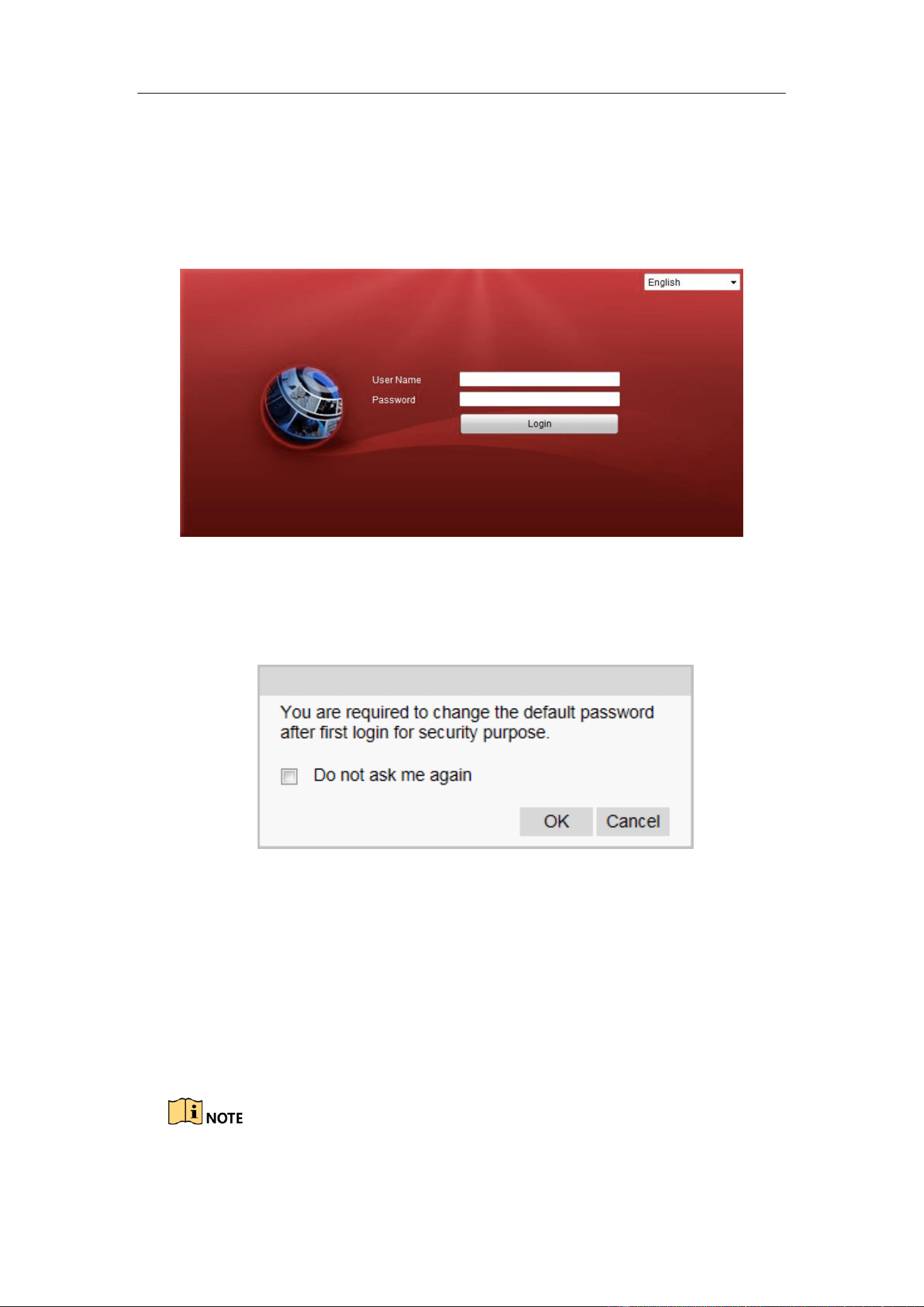
3.3 Logging in via Web Browser
Purpose:
You can log in to the guidance terminal via web browser for further operations such as
live view, playback, local configuration, etc.
Steps:
1. In the address bar of the web browser, input the IP address of the guidance
terminal, and press the Enter key to enter the login interface. A login window
displays.
By default, the IP address of the guidance terminal is 192.0.0.64.
You are recommended to use web browser of IE 8 or above.
2. Input the user name and password of the guidance terminal.
By default, the user name for login is admin and the password is 12345.
You are highly recommended to change the default password right after the
first login to avoid safety problem.
CHANGE DEFAULT PASSWORD–The default Admin account password (12345)
is for first-time log-in purposes only. You must change this default password to better
Guidance Terminal User Manual
17
protect against security risks, such as the unauthorized access by others to the product
that may prevent the product from functioning properly and/or lead to other
undesirable consequences.
3. Click Login.
Figure 3-6 Login Interface
4. You are required to change the default password after first login for security
purpose. Click OK to change the password in User Management interface.
Figure 3-7 Change the Default Password
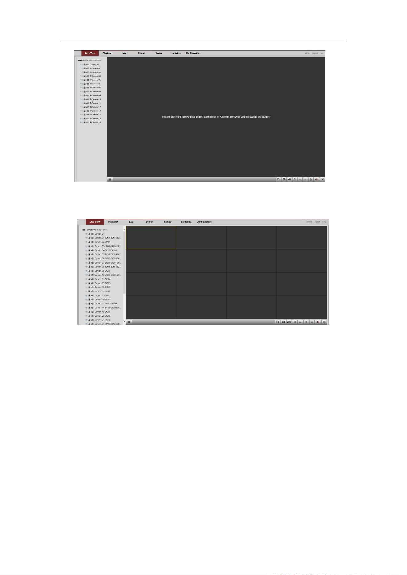
5. For the first time to login, you should install the plug-in before you can access the
functions. Click Please click here to download and install the plug-in. Close
the browser when installing the plug-in. on the live view page, run and install
the plug-in according to the prompt. After the installation of plug-in, re-open the
web browser and login.
Please close your web browser during the installation of the plug-in.
Guidance Terminal User Manual
18
Figure 3-8 Install the Plug-in
6. After login, the interface is shown as below.
Figure 3-9 Live View Window
Guidance Terminal User Manual
19
Chapter 4 Configuration
Purpose:
The parameters, such as protocol, stream type, network, alarm, etc., can be configured
via the web browser.
Click Configuration tab to enter the Configuration page.
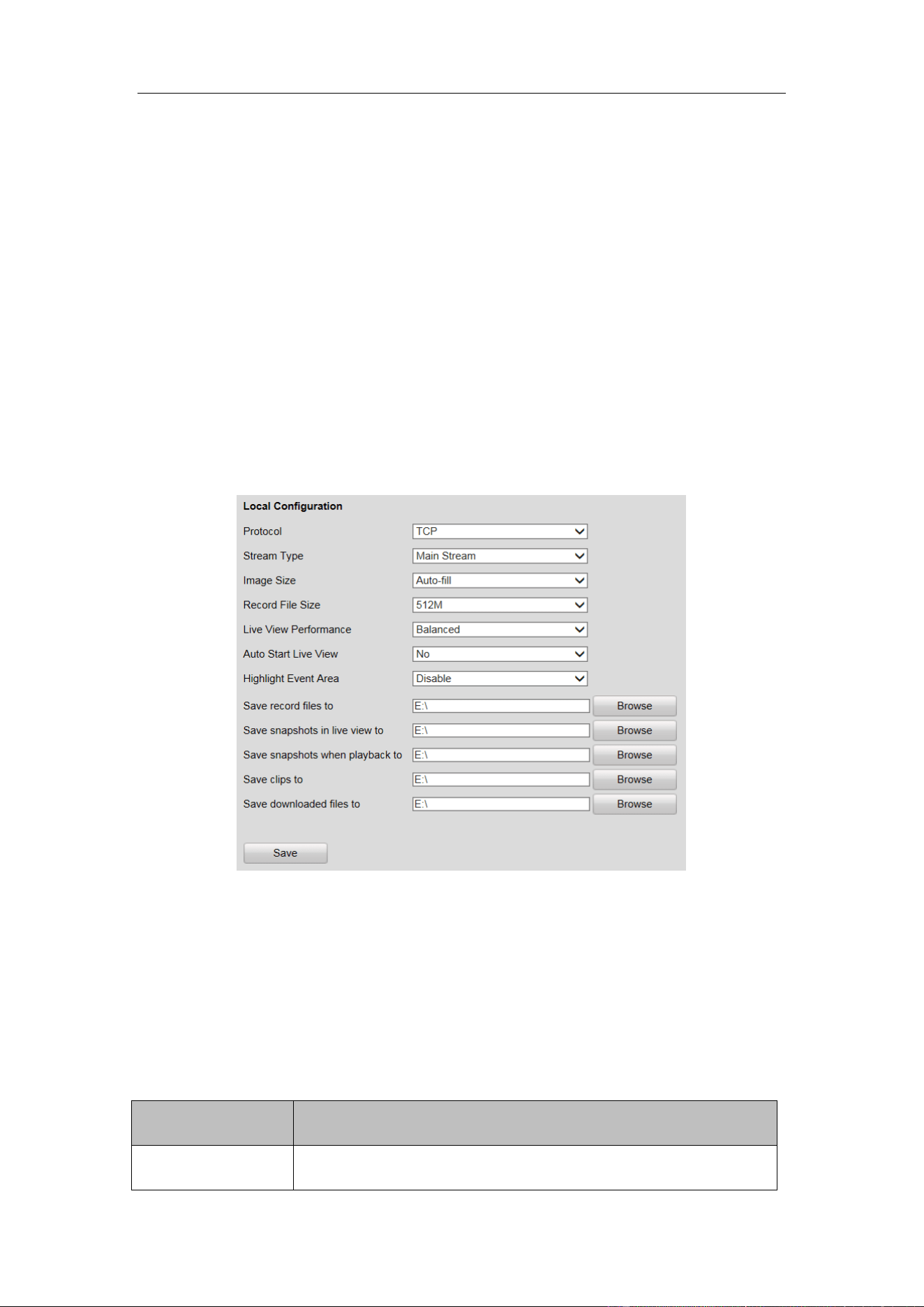
4.1 Local Configuration
Steps:
1. Go to Configuration > Local Configuration.
Figure 4-1 Local Configuration
2. Set the corresponding parameters such as protocol, stream type, image size, etc.
as desired.
3. Click Browse to select a local saving path for the files.
4. Click Save to save the settings.
Refer to the following descriptions of local configuration parameters.
Parameter
Description
Protocol
TCP/UDP are selectable.

Guidance Terminal User Manual
20
Parameter
Description
Stream Type
Main Stream/Sub-Stream are selectable.
Image Size
Auto-fill/4:3/16:9 are selectable.
Record File Size
256M/512M/1G are selectable.
Live View
Performance
Shortest Delay/Real Time/Balanced/Fluency are selectable.
Auto Start Live
View
No/Yes are selectable.
Highlight Event
Area
Enable/Disable are selectable.
Save record files to
C:\Users\TSP Web\ RecordFiles (Default Path)
Save snapshots in
live view to
C:\Users\TSP Web\ CaptureFiles (Default Path)
Save snapshots
when playback to
C:\Users\TSP Web\PlaybackPics (Default Path)
Save clips to
C:\Users\TSP Web\PlaybackFiles (Default Path)
Save downloaded
files to
C:\Users\TSP Web\DownloadFiles (Default Path)
4.2 Remote Configuration
4.2.1 Configuring Device Parameters
Configuring Device Information
You can edit the Device Name and Device No., and view the device Model, Serial No.,
Firmware Version, Encoding Version, Number of Channels, Number of HDDs,
Number of Alarm Input and Number of Alarm Output in the Basic Information
interface.
Guidance Terminal User Manual
21
Figure 4-2 Basic Information
Configuring Time
You can configure the time in the Time Settings interface, including Time Zone,
synchronization (NTP Time Synchronization or Manual Time Synchronization).
Figure 4-3 Time Setting
NTP: After enabling NTP, the NTP server will synchronize the device time at regular
intervals. Click before NTP to enable it, and input the Server Address, NTP Port
and Interval.
Manual Time Sync.: After enabling Manual Time Synchronization, the device time
Guidance Terminal User Manual
22
can be synchronized with the setting time or the computer time. Click before
Manual Time Sync. to enable it, and input the time as desired. Or you can check the
checkbox of Sync. with computer time.
4.2.2 Managing Camera
In the IP Camera interface, the guidance terminal is capable of connecting up to 32
parking cameras.
Figure 4-4 IP Camera Management
Activating Parking Camera
If the parking camera is inactive, it will be listed in the Abnormal Parking Camera
List. You can activate the inactive cameras in batch.
Figure 4-5 Batch Activation
1. Check the inactive parking camera(s).

Guidance Terminal User Manual
23
2. Click Batch Activation.
Figure 4-6 Batch Activation
3. Enter the password, and confirm it.
STRONG PASSWORD RECOMMENDED–We highly recommend you create
a strong password of your own choosing (Using a minimum of 8 characters,
including at least three of the following categories: upper case letters, lower case
letters, numbers, and special characters.) in order to increase the security of your
product. And we recommend you reset your password regularly, especially in the
high security system, resetting the password monthly or weekly can better protect
your product.
4. Click OK to activate the camera(s).
Adding Parking Camera
Click Auto Distribute IP and the IP address of the camera is auto- allocated. The
fourth number of the host ranges from 2 to 17. If the IP is occupied, the number
will be extended and if the IP is not in the specified network segment of the guide
terminal, the IP of camera will be modified to be in the same network segment
with the system.
The status of the camera will be Offline if the camera is not connected.
When the camera is connected, the IP address will be allocated according to the
network interface of the camera and the fourth number of the host ranges from 2
to 17. The status of the camera will be Online.
Guidance Terminal User Manual
24
Modifying Parking Camera
1. Select a camera and the item becomes blue.
2. Click Modify and you can modify the information including user name and
password.
Figure 4-7 Modify Parking Camera
3. (Optional) Click Copy to to copy the settings to other camera(s).
4. Click OK to save the settings.
Configuring Custom Protocol
Click Custom Protocol to configure the protocol as follows.
Guidance Terminal User Manual
25
Figure 4-8 Custom Protocol
Getting Access to Parking Camera
When the camera is online, you can click Access and a login interface for a camera is
linked. Log in to the camera to configure the parking camera parameters as follows.
Figure 4-9 Access
You must configure the IP address of parking camera remote host and port before the
parking camera data is received by the guidance terminal.
Guidance Terminal User Manual
26
4.2.3 Configuring Camera
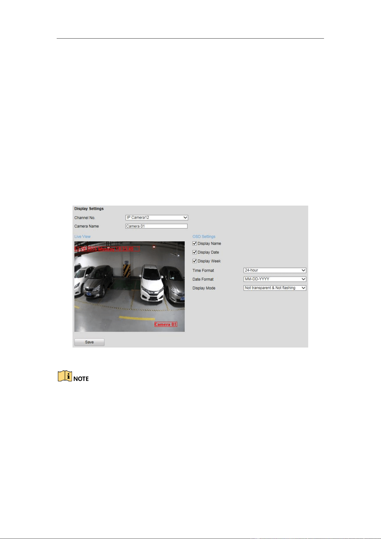
Configuring Display
In the Display Settings interface, you can configure the channel name and OSD
settings.
Channel No.: Select the channel number from the dropdown list.
Camera Name: Customize a camera name.
OSD Settings: You can check the checkbox to display camera name, date and week
information on the live view screen. You can also set the time and data format and
display mode.
Figure 4-10 OSD Settings
You can drag the name, date, week, time information to any position of the live view
window.
Configuring Parking Space
You can configure the recognized parking space number, parking space area, and
special parking space in parking space allocation.
1. Go to Configuration > Remote Configuration > Camera Settings > Parking
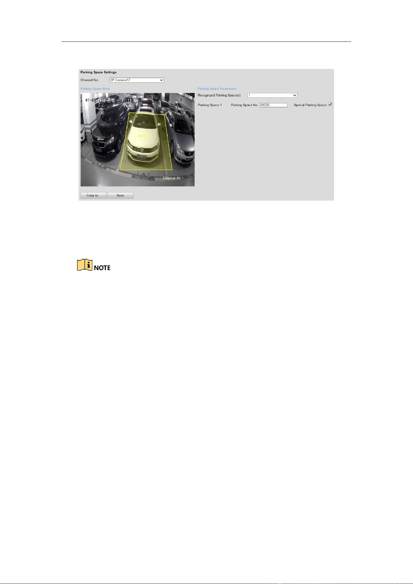
Guidance Terminal User Manual
27
Space Settings.
Figure 4-11 Parking Space Settings
2. Select the Channel No.
3. Select the number of the Recognized Parking Space(s) from the drop-down list.
The selectable value may vary according the camera models.
4. Input the Parking Space No. in the text filed.
5. (Optional) If the space is a special space, check Special Parking Space
checkbox.
6. Draw parking spaces.
According to the number of spaces you set, the quadrilaterals appear in the image.
1) Click a quadrilateral, and drag corner of the quadrilateral to adjust the shape of
it, or drag the quadrilateral to adjust the location of it.
2) Repeat step 1) to configure other quadrilaterals.
7. (Optional) Click Copy to… to copy the settings to other cameras.
8. Click Save to save the settings.
Configuring Parking Space Indicator
The indicator displays the space status, different colors stand for different status. You
can select the indicator and the color of different status.
Steps:
1. Go to Configuration > Remote Configuration > Camera Settings > Parking
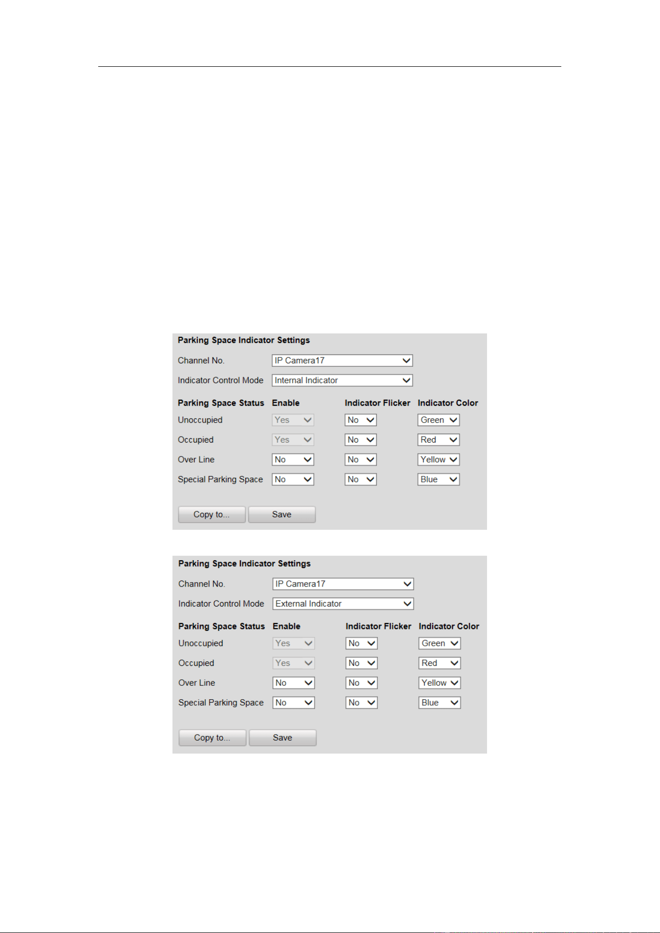
Guidance Terminal User Manual
28
Space Indicator.
2. Select the Channel No.
3. Select the indicator in the drop-down list of Indicator Control Mode on your
demand, including Internal Indicator, External Indicator, and Internal and
External Indicator.
If you select the Internal Indicator or External Indicator, and when all the
detected parking spaces are occupied, the indicator turns to the occupied color;
when the detected parking spaces are not all occupied, the indicator remains
the unoccupied color.
If you select the Internal and External Indicator, the indicators work at the
same time, you can respectively configure the indicator to display the status
of each parking space.
Figure 4-12 Configure Internal Indicator
Figure 4-13 Configure External Indicator
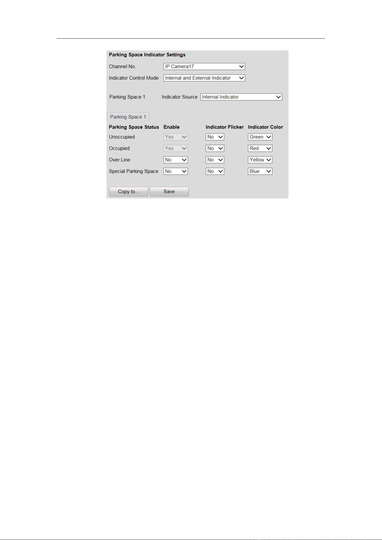
Guidance Terminal User Manual
29
Figure 4-14 Configure Internal and External Indicator
4. Set the indicator parameters for different parking space status.
The description of different status is shown below:
Unoccupied: The space is free.
Occupied: The space is occupied by a vehicle.
Over Line: A vehicle occupied two parking spaces.
Special Parking Space: The space is specified to a certain vehicle.
1) If you choose Internal and External Indicator, click the tab of the parking
space No. (e.g. Parking Space 1) and select the indicator in the Indicator
Source drop-down list.
2) Configure the following parameters on your demand.
Enable: Select Yes or No to enable or disable the indication for the
corresponding status.
Indicator Flicker: Set the indicator flicker or not for the corresponding status.
Indicator Color: Choose the color of the indicator for the corresponding
status.
5. (Optional) Click Copy to… to copy the settings to other cameras.
6. Click Save to save the settings.
Configuring Capture Parameters
You can configure the capture parameters as below.
Steps:
1. Go to Configuration > Remote Configuration > Camera Settings > Capture
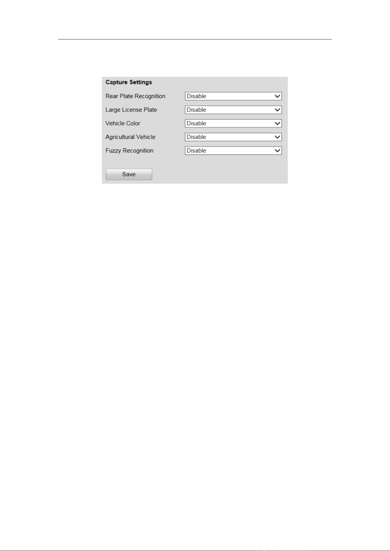
Guidance Terminal User Manual
30
Parameters.
2. Enable or disable the parameters as below.
Figure 4-15 Configure Capture Parameters
Rear Plate Recognition: Enable or disable the license plate recognition when the
vehicle is backed into the space.
Large License Plate: Normally, the camera is recommended to be placed about 5
m away from the parking space to ensure the plate recognition accuracy. But if
the parking camera is placed much nearer to the space than the recommended
distance, the license plate possesses greater pixels in the image which will make
it looks large, then you should enable the Large License Plate function to improve
the accuracy of the license plate recognition.
Vehicle Color: Enable or disable vehicle color recognition.
Agricultural Vehicle: For the license plate of agricultural vehicles, they are
much different from other ones of normal vehicles. Enable the Agricultural
Vehicle function to recognize the license plate number of agricultural vehicles.
Fuzzy Recognition: Enable or disable fuzzy recognition of the license plate.
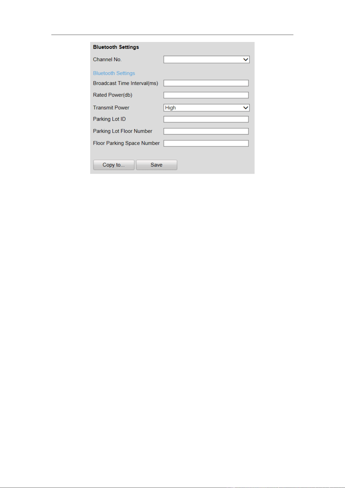
Configuring Bluetooth
If Bluetooth parking camera is connected, you can configure the Bluetooth
parameters.
Steps:
1. Go to Configuration > Remote Configuration > Camera Settings > Bluetooth
Settings.
Guidance Terminal User Manual
31
Figure 4-16 Bluetooth Configuration
2. Select the Channel No.
3. Configure the Bluetooth parameters.
Broadcast Time Interval: the frequency of sending broadcast frame by
Bluetooth module.
Rated Power: the signal strength received by mobile client which is 1 meter
away from the parking camera.
Transmit Power: Three levels are selectable. The stronger the transmit power,
the further the receivable distance.
Parking Lot ID: Hex number can be entered (0 - F).
Parking Lot Floor Number: Configure according to the actual conditions.
Floor Parking Space Number: Configure according to the actual conditions.
Configuring Video
You can configure the video parameters in the Video Settings interface including
stream type, video type, resolution, etc.
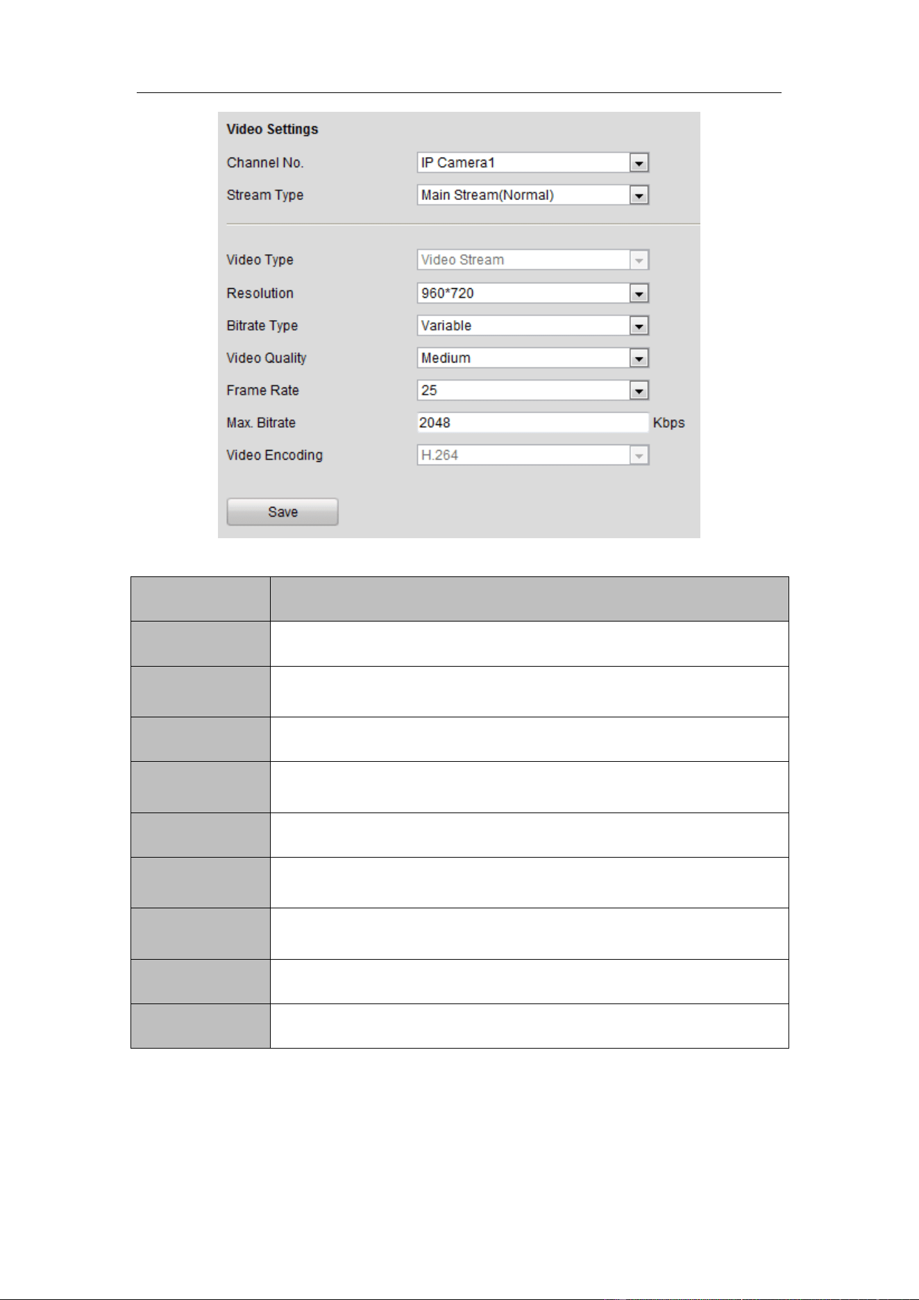
Guidance Terminal User Manual
32
Figure 4-17 Video Settings
Parameters
Description
Channel No.
Up to 32 channels.
Stream Type
Main Stream (Normal)/Sub Stream/Main Stream (Event) are
selectable.
Video Type
Video Stream
Resolution
The higher the resolution, the clearer the image, and the larger
bandwidth it needs.
Bitrate Type
Variable/Constant is selectable.
Video Quality
Highest/Higher/Medium/Low/Lower/Lowest. By default, it is
Medium.
Frame Rate
The higher the frame rate, the larger bandwidth it needs, and the
larger storage space it needs.
Max. Bitrate
The maximum bitrate.
Video Encoding
H.264.
Configuring Schedule
You can set the record schedule in Schedule Settings interface as follows.
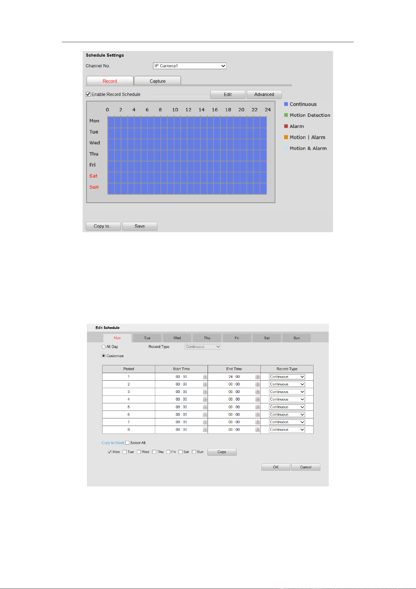
Guidance Terminal User Manual
33
Figure 4-18 Schedule Settings
Steps:
1. Select the channel No. from the drop-down list.
2. Check the checkbox of Enable Record Schedule.
3. Click Edit to set the schedule as follows.
Figure 4-19 Edit Schedule
1) Select All Day or Customize to edit the schedule.
2) Select the Record Type. Continuous, Motion Detection, Alarm, Motion or
Guidance Terminal User Manual
34
Alarm and Motion & Alarm are selectable.
3) If you select Customize, click to set the start time and end time.
4) (Optional) If you want to copy the settings to other days, check the checkbox
and click Copy.
5) Click OK to save the settings.
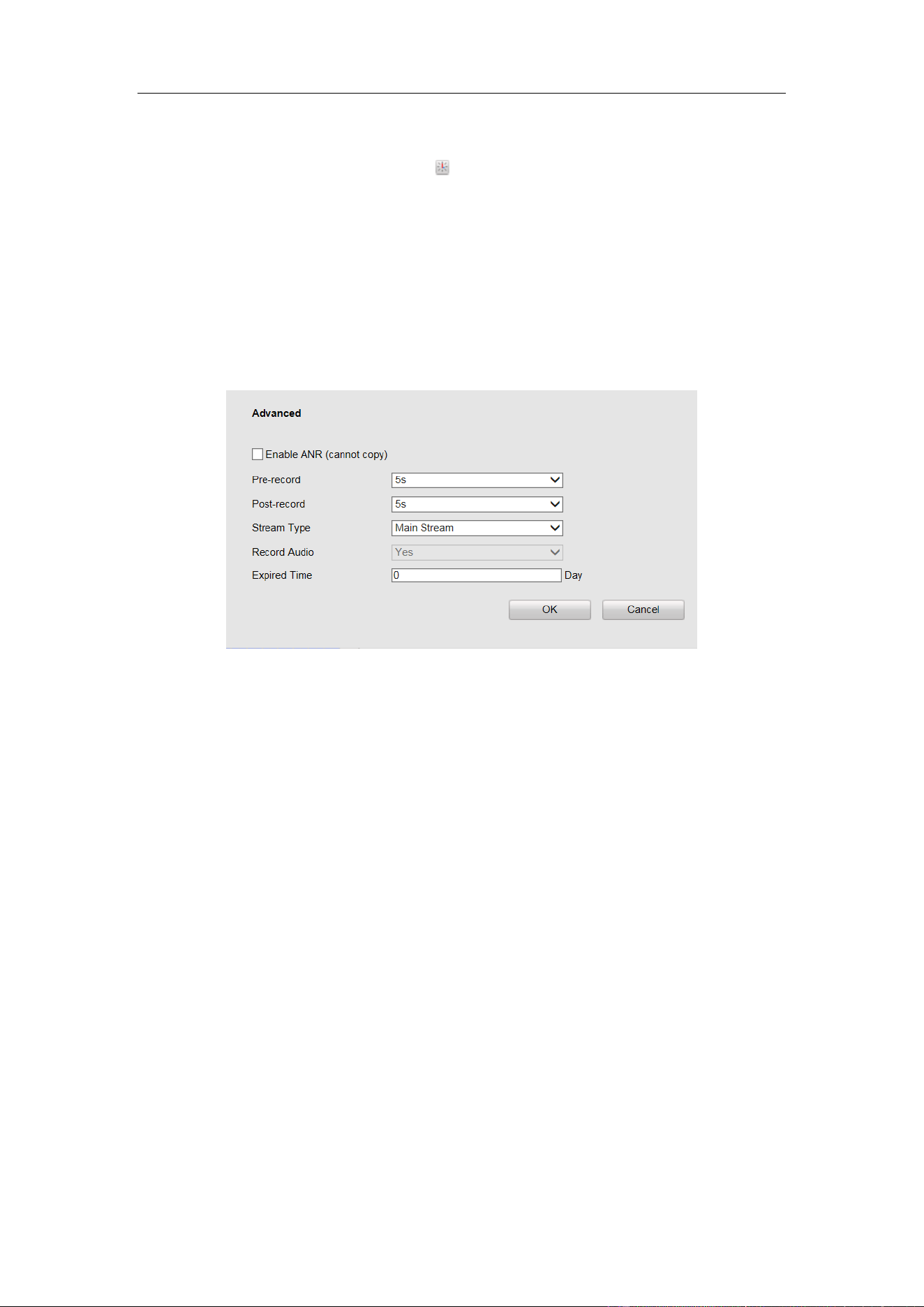
4. Click Advanced in Schedule Settings interface to configure advanced settings as
follows.
Figure 4-20 Advanced Settings
5. (Optional) If you want to copy all the settings to other channels, click Copy to…
and select channels, and then click OK.
6. Click Save to save the settings.
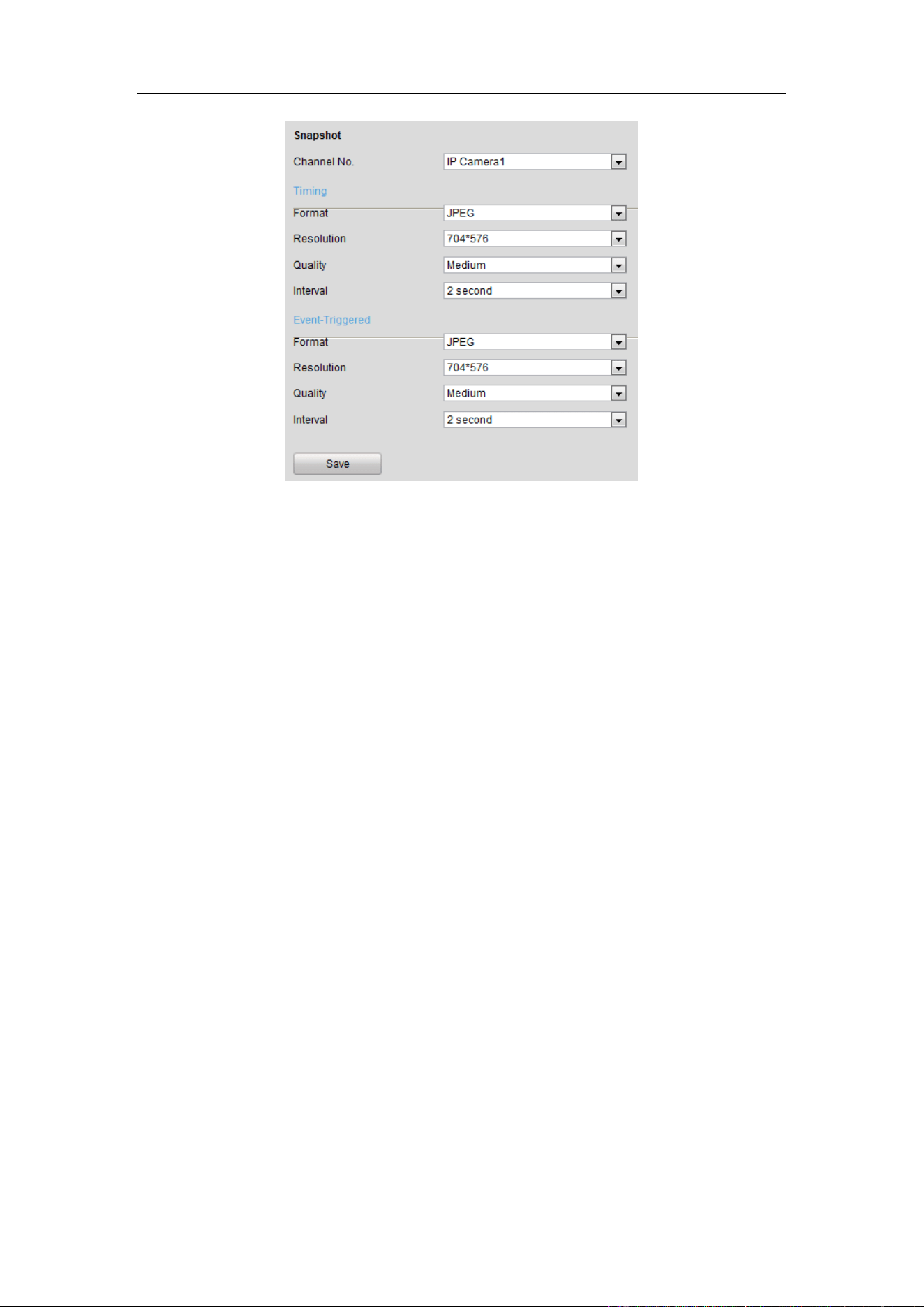
Configuring Snapshot
You can configure the scheduled snapshot and event-triggered snapshot parameters
including format, resolution, quality and interval.
Guidance Terminal User Manual
35
Figure 4-21 Snapshot Settings
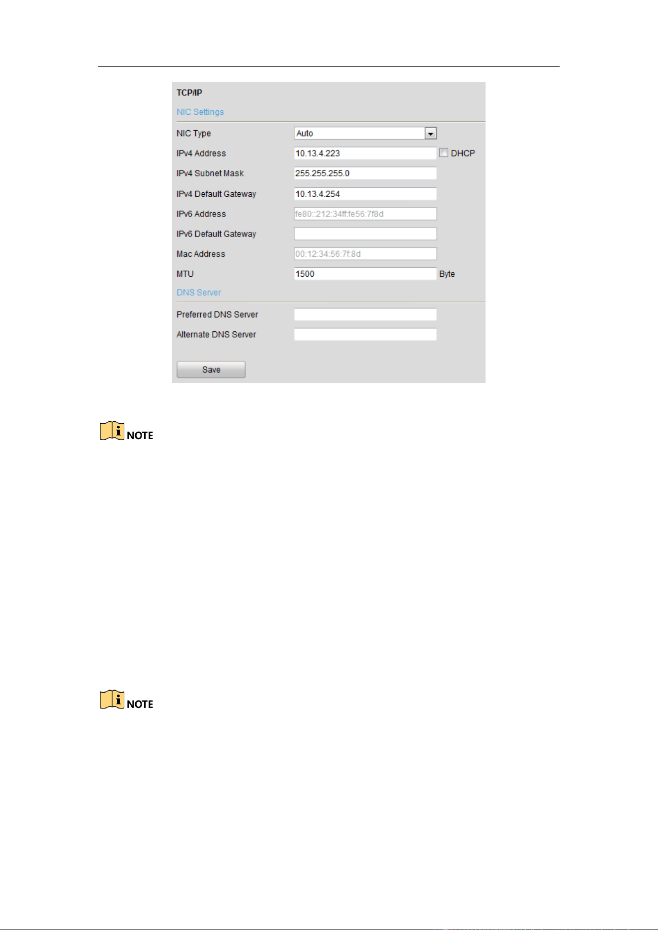
4.2.4 Configuring Network
The guidance terminal is equipped with two network interface cards and you can
configure extranet and intranet parameters respectively.
Configuring TCP/IP
You can configure the IP address of the four 1000M network interface cards.
NIC Type: Auto, 10M Half-dup, 10M Full-dup, 100M Half-dup and 100M Full-dup is
selectable.
The default IP address is 192.0.0.64, which is used to interact with back-end platform.
IP address, subnet mask and gateway can be configured in the following interface.
Guidance Terminal User Manual
36
Figure 4-22 TCP/IP Settings
MTU: The maximum size of data packet in transmission.
You are required to reboot the guidance terminal after modifying the IP address.
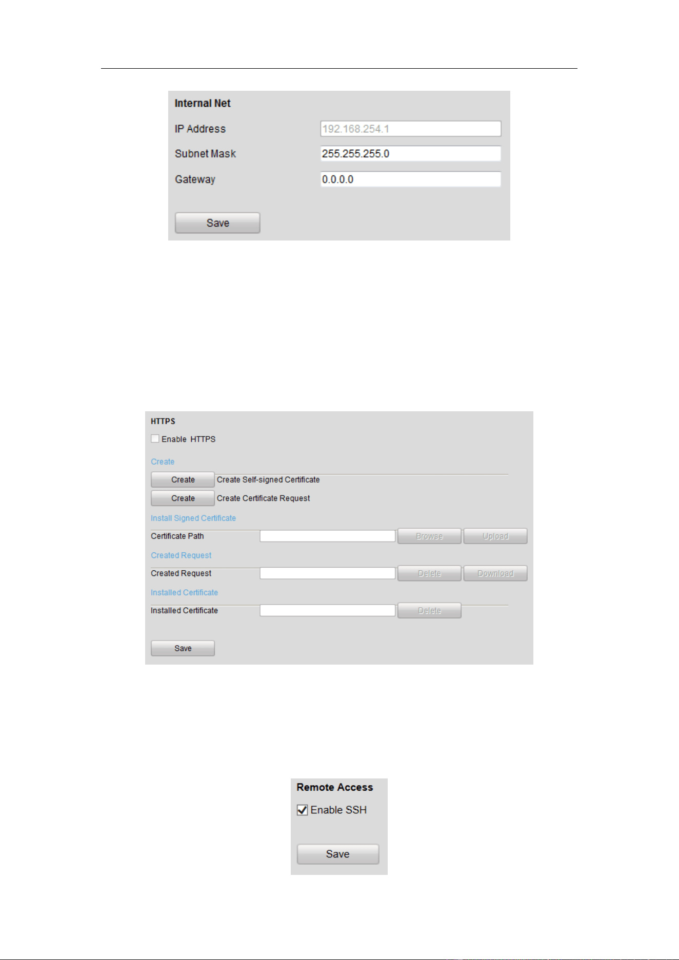
Configuring Internal Net
You can view IP Address and modify subnet mask and gateway of the 16 100M
network interface cards in the following interface.
The default IP address is 192.168.254.1. The 16 network interface cards are in the
same network segment, which can interact with cameras and up to 32 parking cameras
can be accessed.
Network segment: 192.168.254.2~192.168.254.33. Other IP address cannot access to
the guidance terminal.
Guidance Terminal User Manual
37
Figure 4-23 Internal Net Settings
Configuring HTTPS
You can check the checkbox to enable HTTPS in the HTTPS interface and create
self-signed certificate, certificate request and upload, download and delete
certificate.
Figure 4-24 HTTP Settings
Configuring Remote Access
You can check the checkbox to enable SSH in Remote Access interface.
Guidance Terminal User Manual
38
Figure 4-25 Remote Access Settings
4.2.5 Configuring Serial Port
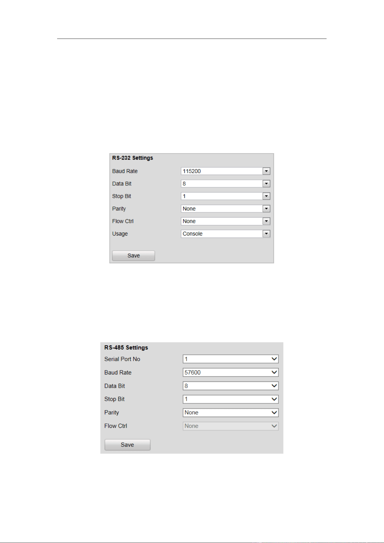
Configuring RS-232 Serial Port
RS-232 serial port parameters are for the RS-232 interface. Please keep the settings as
default.
Figure 4-26 RS-232 Settings
Configuring RS-485 Serial Port
RS-485 serial port is used for connecting to LED display units, which shows the
available parking spaces and the direction of the parking area.
Figure 4-27 RS-485 Settings
Guidance Terminal User Manual
39
4.2.6 Configuring Alarm
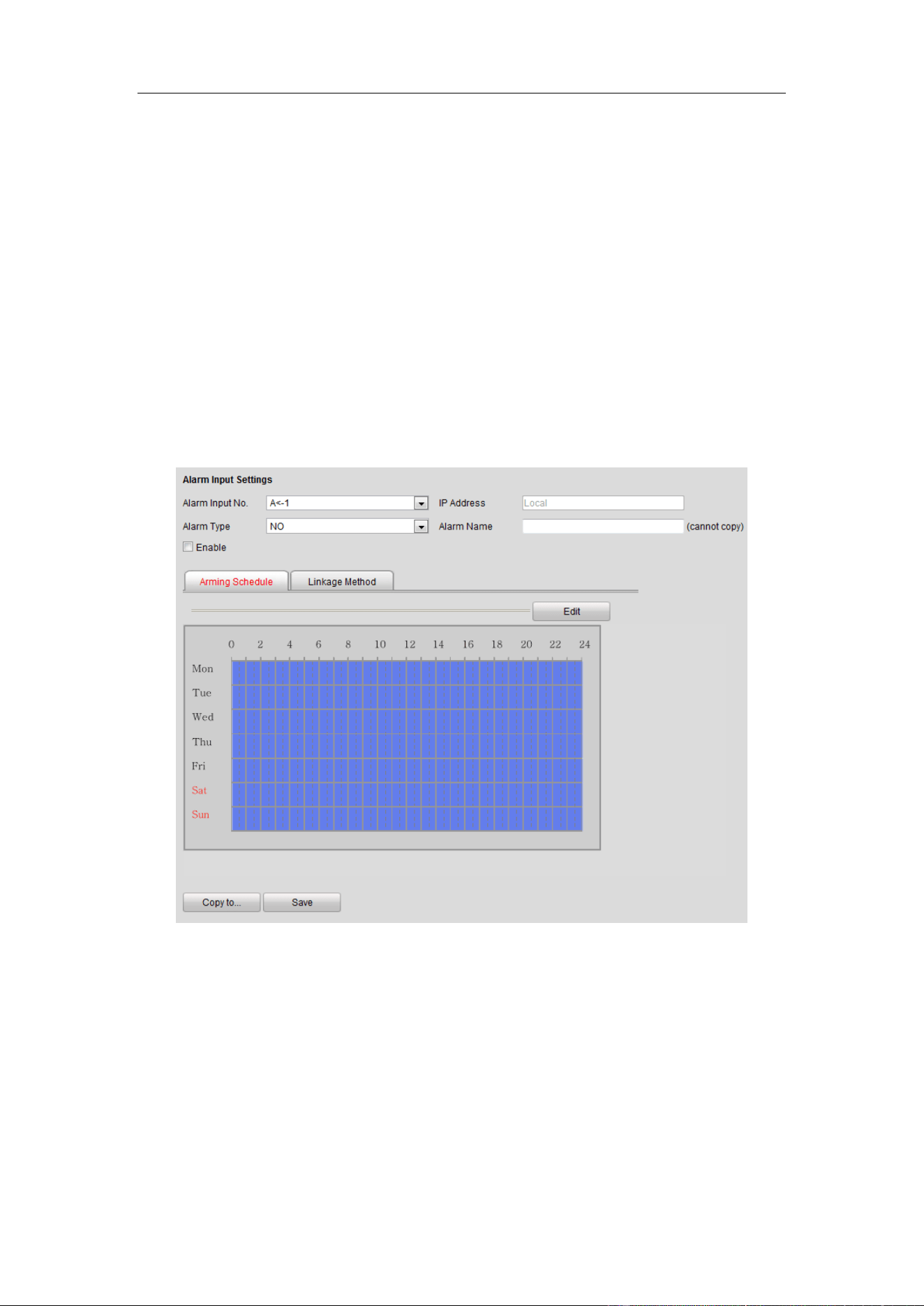
Configuring Alarm Input
Steps:
1. Select the Alarm Input No. from the drop-down list.
2. Select Alarm Type as NO (Remain Open) or NC (Remain Closed).
3. Enter the Alarm Name.
4. Check Enable to enable the alarm input.
5. Click Arming Schedule tab to set the schedule.
Figure 4-28 Alarm Input
6. Click Edit to edit the arming schedule time.
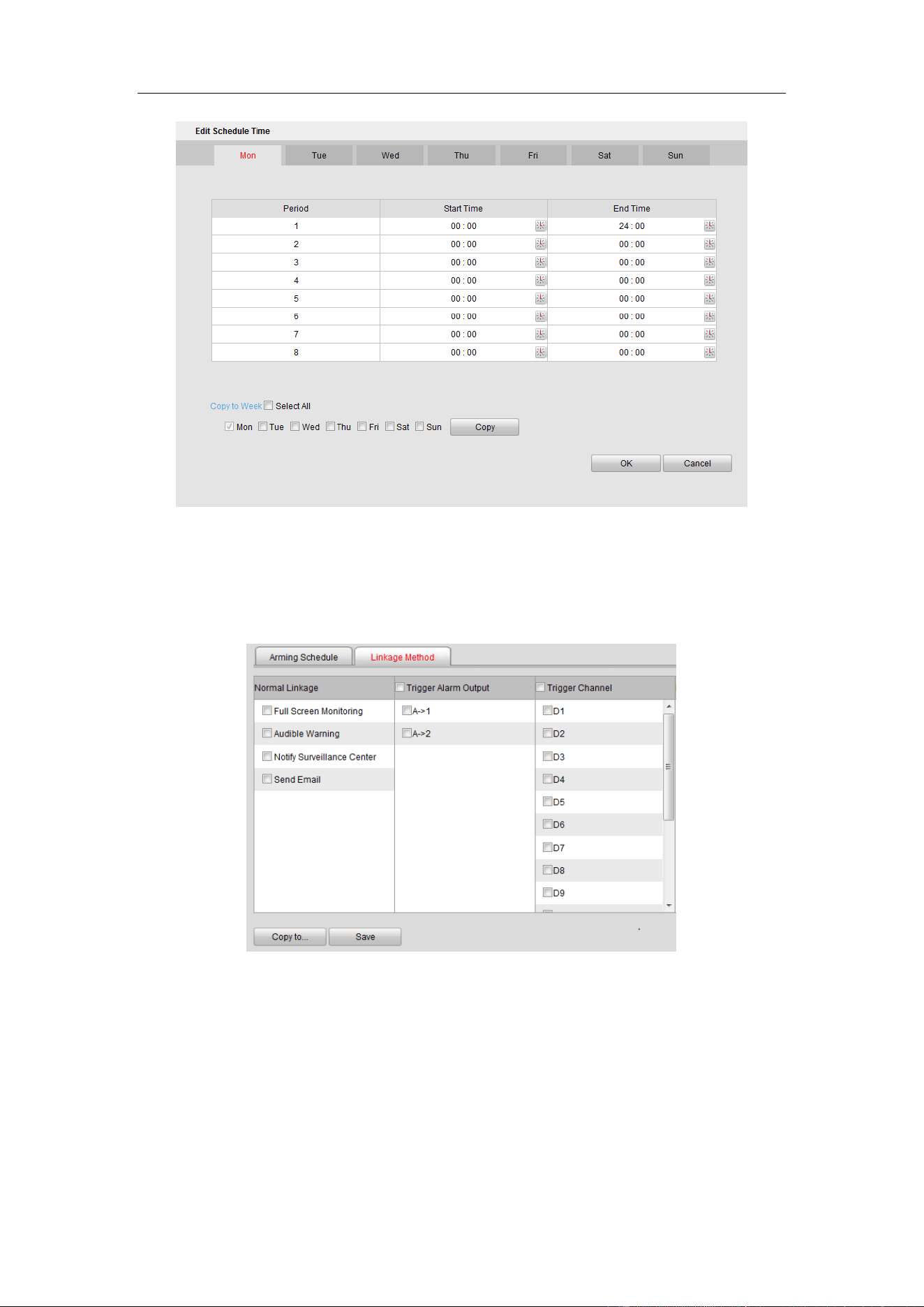
Guidance Terminal User Manual
40
Figure 4-29 Edit Schedule Time
7. Click Linkage Method tab to set the parameters of Normal Linkage, Trigger
Alarm Output, and Trigger Channel.
Figure 4-30 Linkage Method
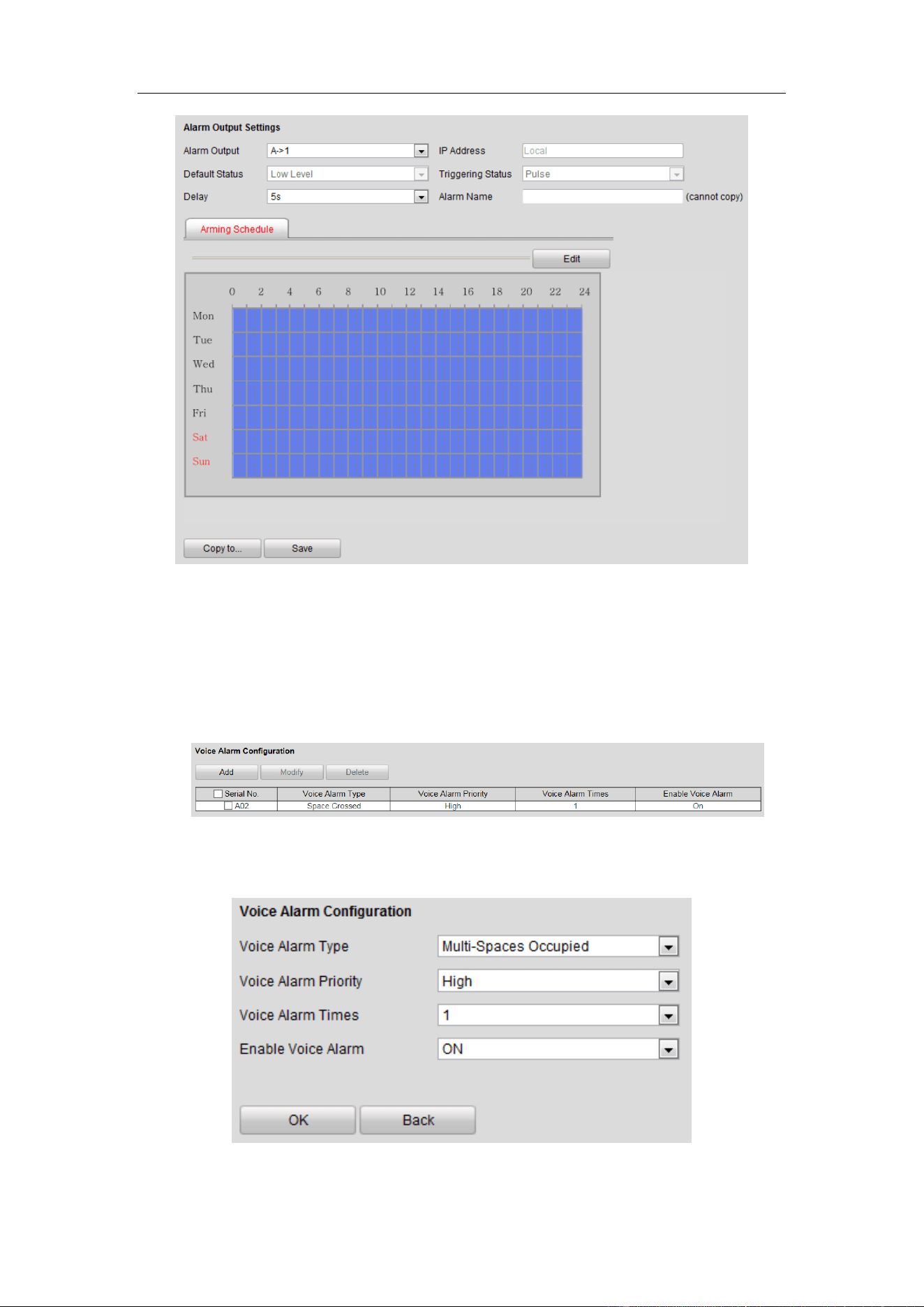
Configuring Alarm Output
Refer to the above section Alarm Input for detailed steps.
Guidance Terminal User Manual
41
Figure 4-31 Alarm Output
Configuring Voice Alarm
Steps:
1. Enter the Voice Alarm Configuration interface.
Figure 4-32 Voice Alarm Configuration
2. Click Add to add voice alarm.
Figure 4-33 Add Voice Alarm
Guidance Terminal User Manual
42
3. Select Voice Alarm Type, Voice Alarm Priority and Voice Alarm Times from the
drop-down lists, and select Enable Voice Alarm as ON.
4. Click OK to save the settings.
4.2.7 Controlling Indicator
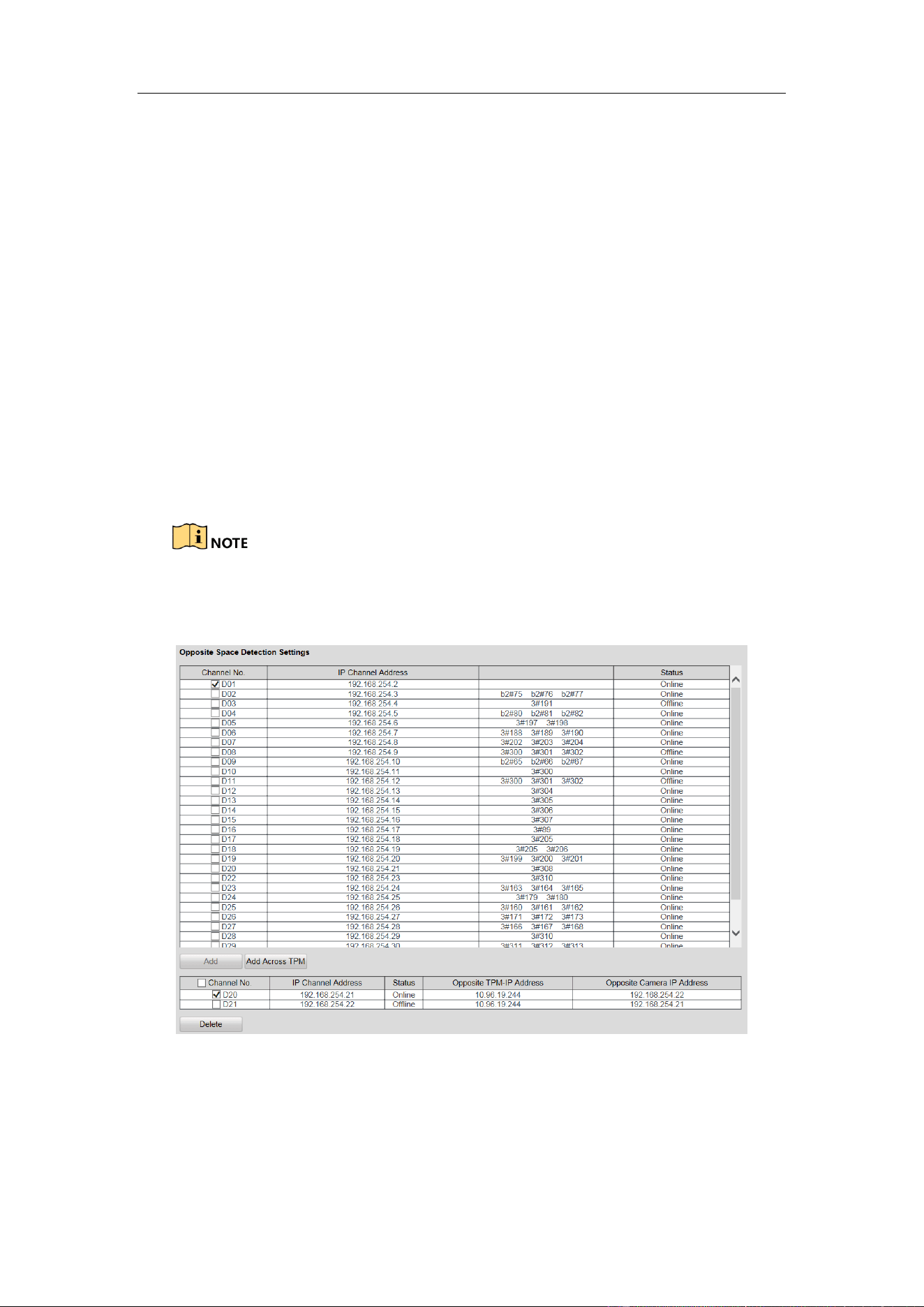
Configuring Opposite Space Detection
The opposite space detection is applicable to the parking lot that the aisle between
the opposite parking spaces is very narrow. After you configure the function, the
indicator of the current parking camera displays the status of opposite space, and
vice versa.
The parking space indicator configuration of two cameras for opposite space
detection must be the same.
Figure 4-34 Opposite Space Detection Settings
Steps:
1. Check two cameras for opposite space detection.
2. Click Add to set the selected two cameras to detect the opposite parking space.
Guidance Terminal User Manual
43
If the camera needs to detect the parking space of another camera under other
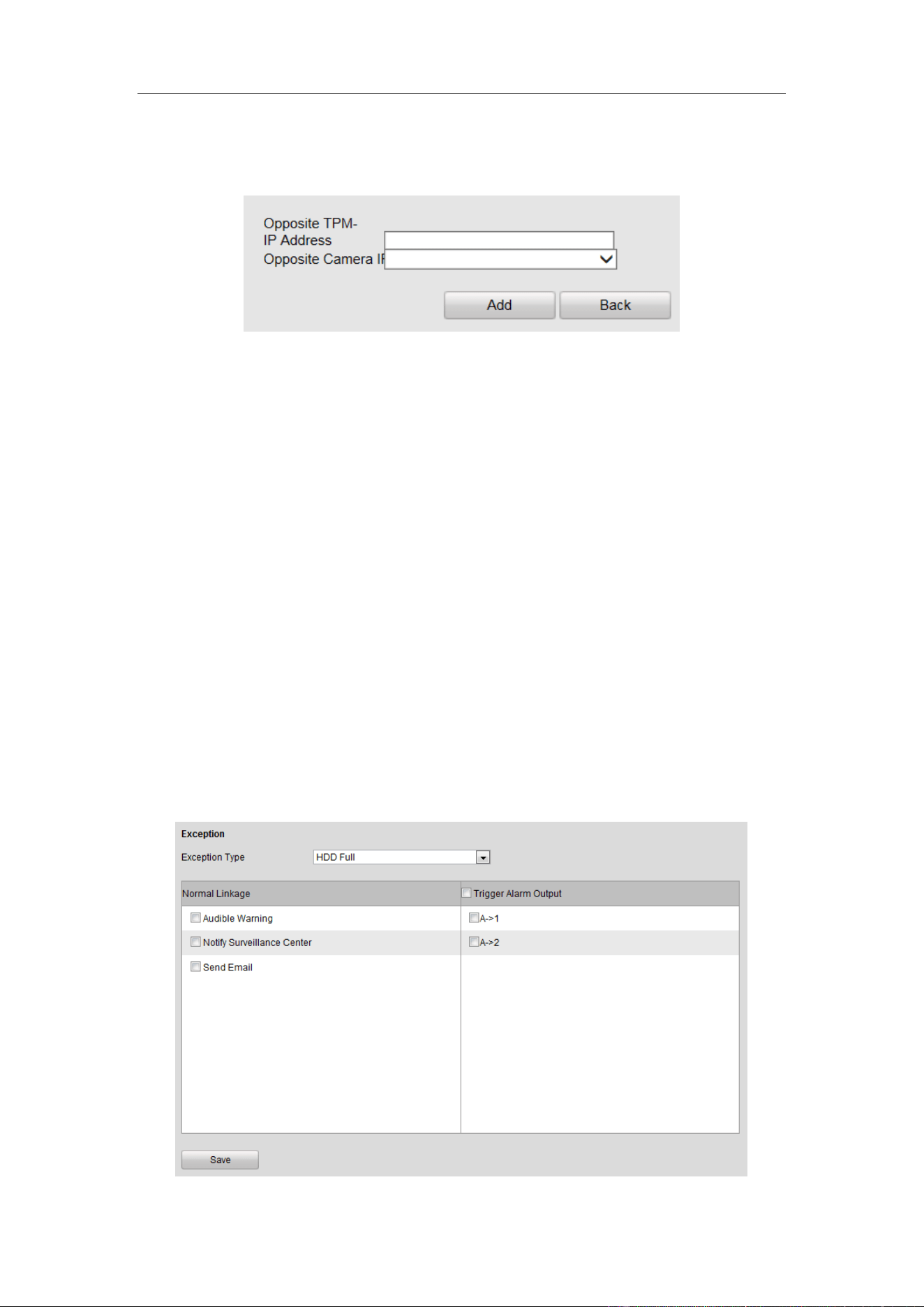
guidance terminal, select the camera and click Add Across TPM.
Figure 4-35 Add Across TPM
3. Enter Opposite TPM-IP Address and select Opposite Camera IP Address.
Opposite TPM is another guidance terminal which needs to be controlled.
Opposite camera is another parking camera which needs to be controlled.
4. Click Add to save the settings.
4.2.8 Configuring Exception
You can set the alarm output method when exception happens. Exception type
includes HDD Full, HDD Error, Network Disconnected, IP Address Conflicted,
Illegal Login and Record/Capture Exception. The alarm output method includes
Normal Linkage (Audible Warning, Notify Surveillance Center and Send Email) and
Trigger Alarm Output.
Guidance Terminal User Manual
44
Figure 4-36 Exception
Refer to the following descriptions of Exception Type.
Exception Type
Description
HDD Full
All the HDD space is full.
HDD Error
Error when writing in the HDD or the HDD is not
initialize.
Network Disconnected
The network is not connected.
IP Address Conflicted
IP addresses are conflicted.
Illegal Login
Wrong password.
Record/Capture Exception
Exception of record or capture.
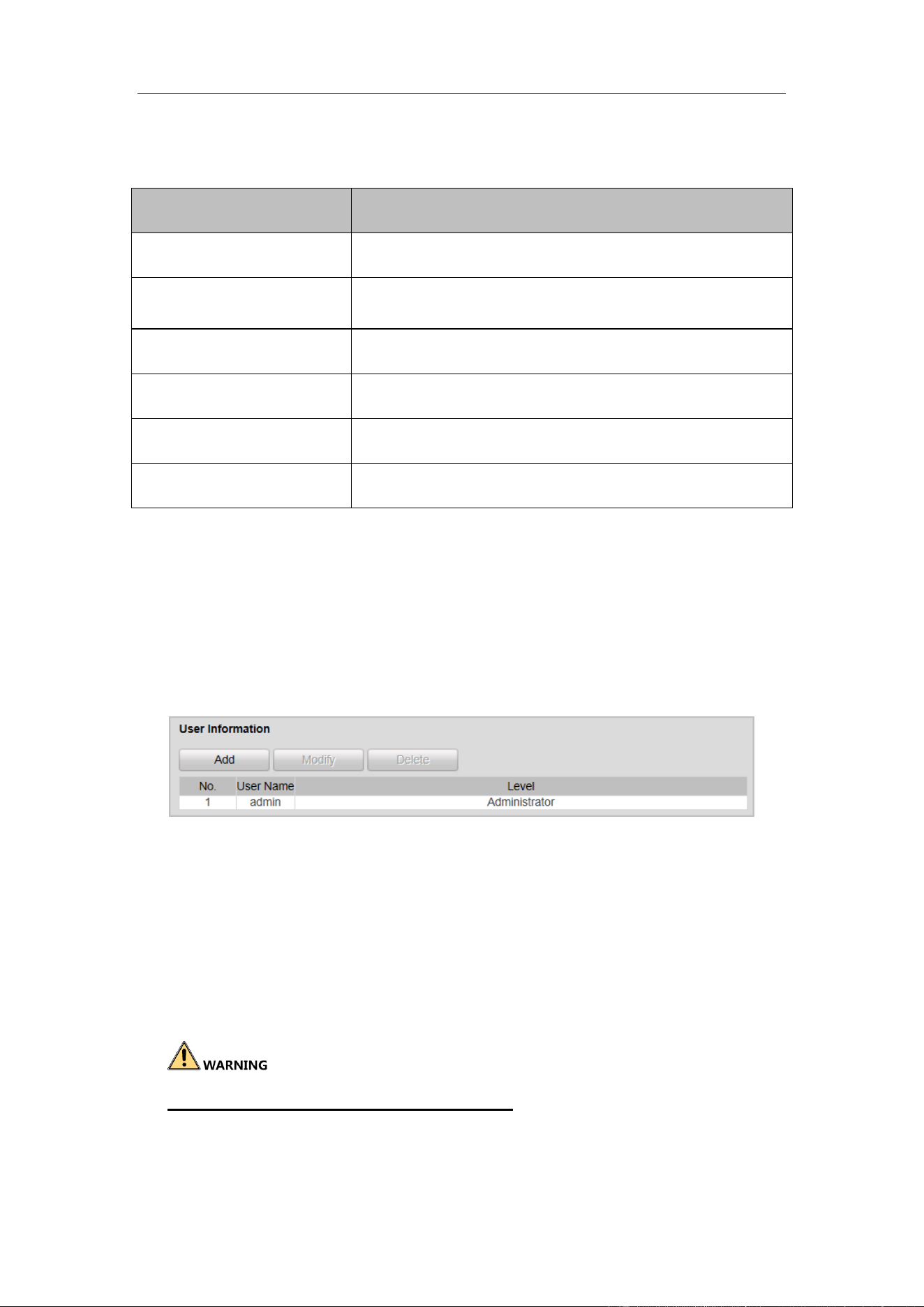
4.2.9 Managing User
You can add, modify and delete users and set user permission in User Management
interface.
By default, there is only one user account admin and the level is Administrator.
Figure 4-37 User Management
Adding a User
Steps:
1. Click Add in the User Management interface.
2. Enter the User Name and Password as desired.
STRONG PASSWORD RECOMMENDED– We highly recommend you create
a strong password of your own choosing (using a minimum of 8 characters, and
contains at least three kinds of following categories: upper case letters, lower case
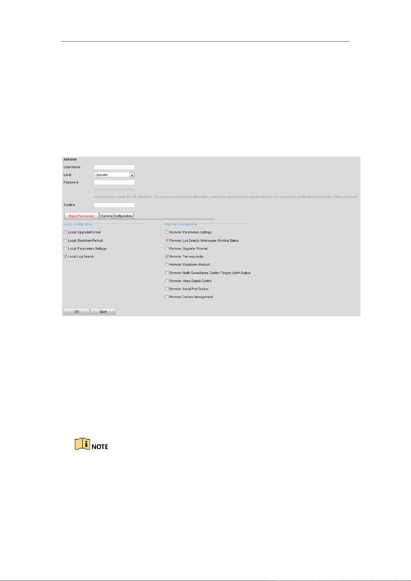
Guidance Terminal User Manual
45
letters, numbers, and special characters) in order to increase the security of your
product.
3. Select the level as Operator or User.
4. Confirm the password.
5. Select the user permission including Basic Permission and Camera
Configuration Permission by checking the checkbox.
Figure 4-38 Add a User
6. Click OK to save the settings.
Modifying a User
Steps:
1. Select the user account for modifying and click Modify.
2. You can modify the user name, password, level and permission.
For admin account, you can only modify the password.
We recommend you to use strong password for security purpose.
3. Click OK to save the settings.
Guidance Terminal User Manual
46
Deleting a User
Select the user account for deleting and click Delete.
You cannot delete the admin account.
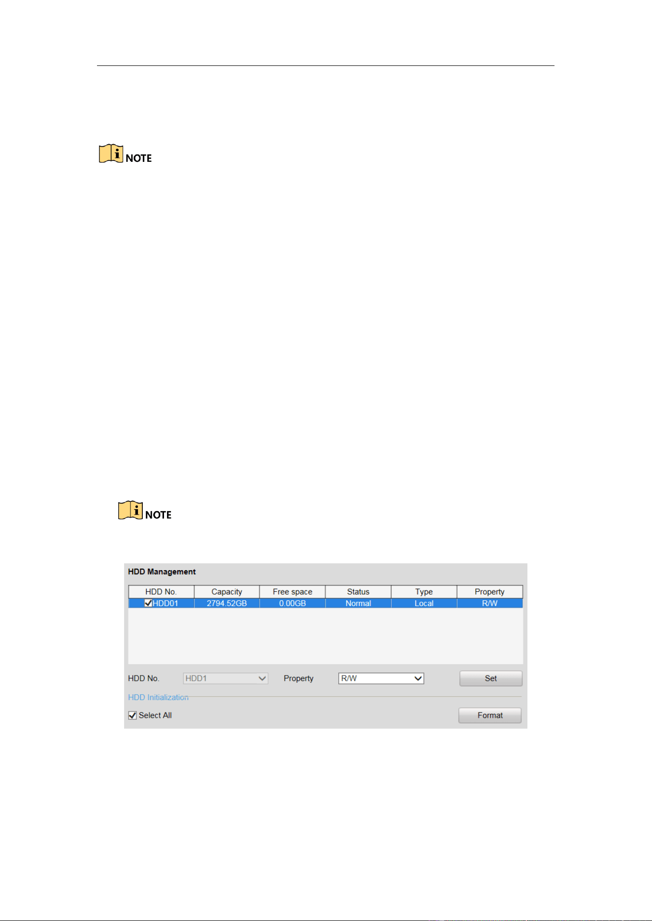
4.2.10 Managing HDD
The device supports HDD management for the purpose of stable and reliable storage.
Configuring Basic Settings
Steps:
1. You can select the HDD No. and set the property as R/W, Read-only or
Redundancy.
2. Click Set to save the settings.
3. (Optional) Select the HDD in the list and click Format to initialize the selected
HDD.
Initialization removes all the data saved in the HDD.
Figure 4-39 HDD Management Interface
Configuring Picture Quota
You can set the space of the picture by setting Picture Quota, and the rest space will
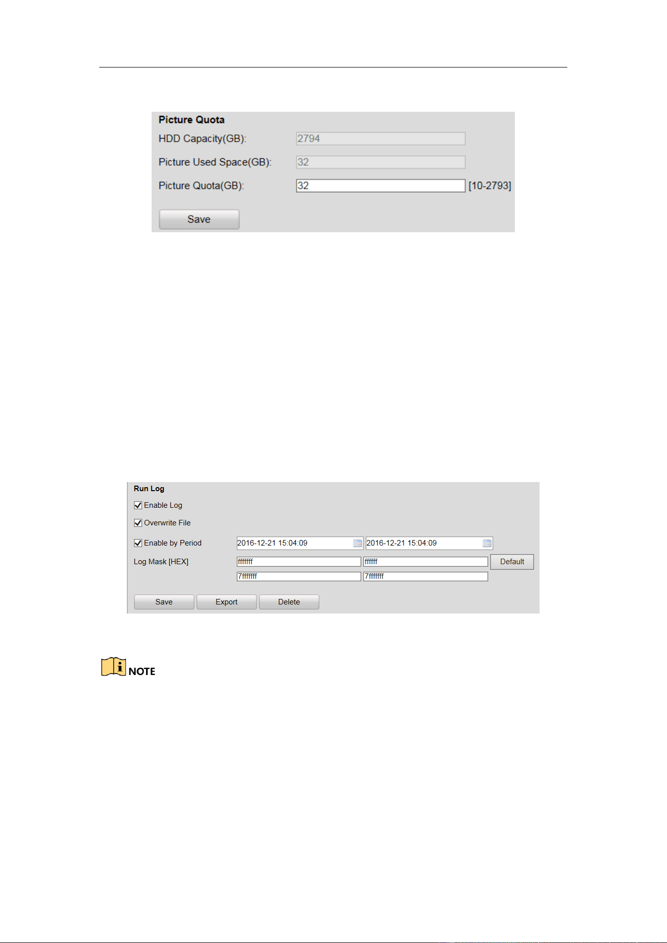
Guidance Terminal User Manual
47
be used to save the record files.
Figure 4-40 Quota Allocation
4.2.11 Running Log
Running log is used for the research and development personnel to debug the device.
Steps:
1. Check Enable Log. Then the log will be saved as file to save in the guidance
terminal.
2. Check Overwrite File.
3. (Optional) Check Enable by Period and set the time period for saving the log.
4. Click Save to save the settings.
5. (Optional) Click Export to export the log or click Delete to delete the log.
Figure 4-41 Run Log
The log mask is the module of printing log. The default log mask is to print err
information.
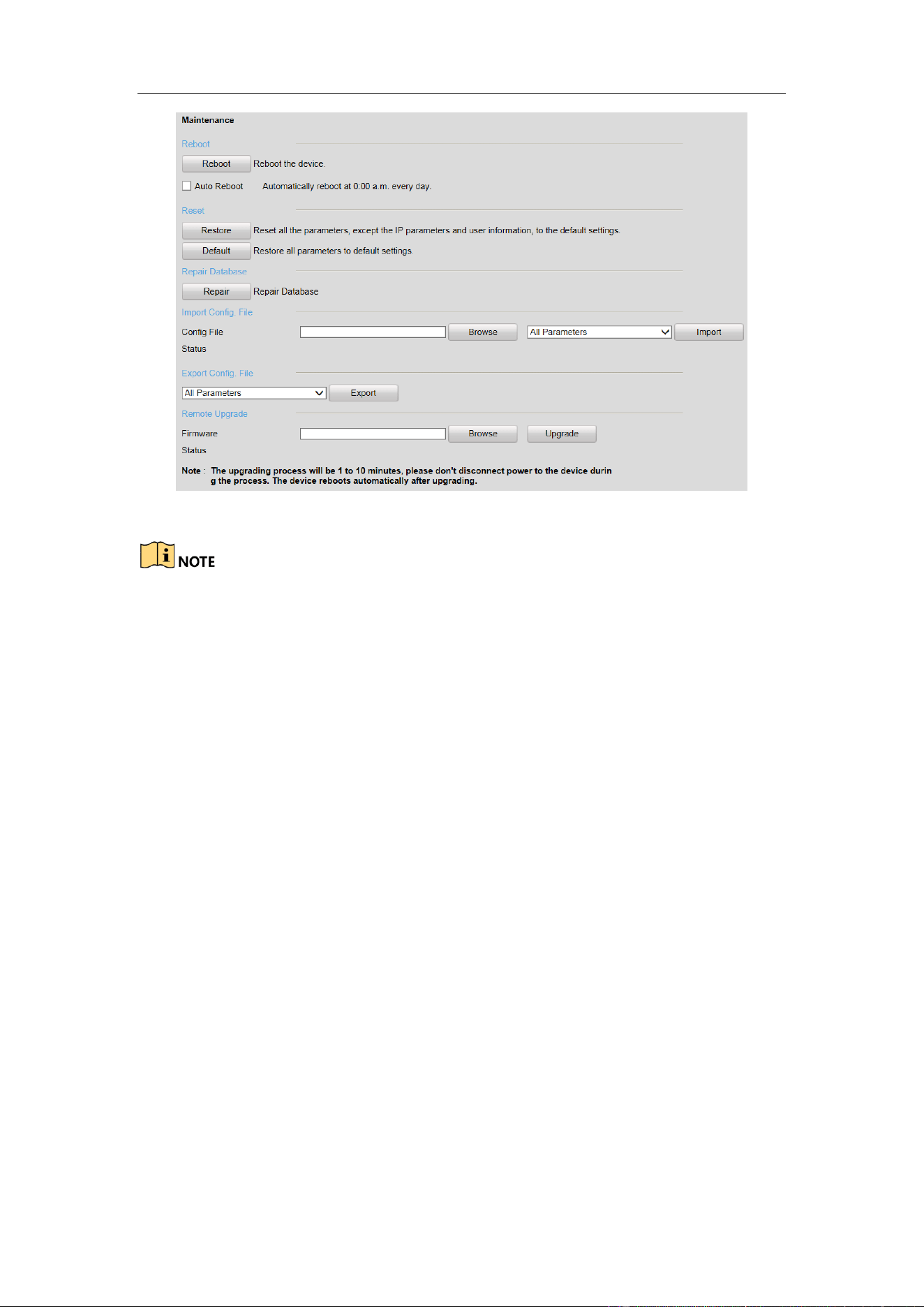
4.2.12 Maintenance
You can operate some maintenance functions in Maintenance interface including
Reboot, Reset, etc.
Guidance Terminal User Manual
48
Figure 4-42 Maintenance
The upgrading file is digicap.dav.
The upgrading process will be 1 to 10 minutes. Please do not disconnect power to
the device during the process.
The device will reboot automatically after upgrading.
4.2.13 Connecting to Platform
The guidance terminal can connect to Ehome and Hik-Connect.
Accessing to Ehome
The guidance terminal can connect to Ehome to realize real-time monitoring,
transmission, storage, management, etc. via network.
Steps:
1. Go to Configuration > Remote Configuration > Platform Settings.
2. Check Enable checkbox.
3. Select the Platform Access Mode as Ehome.
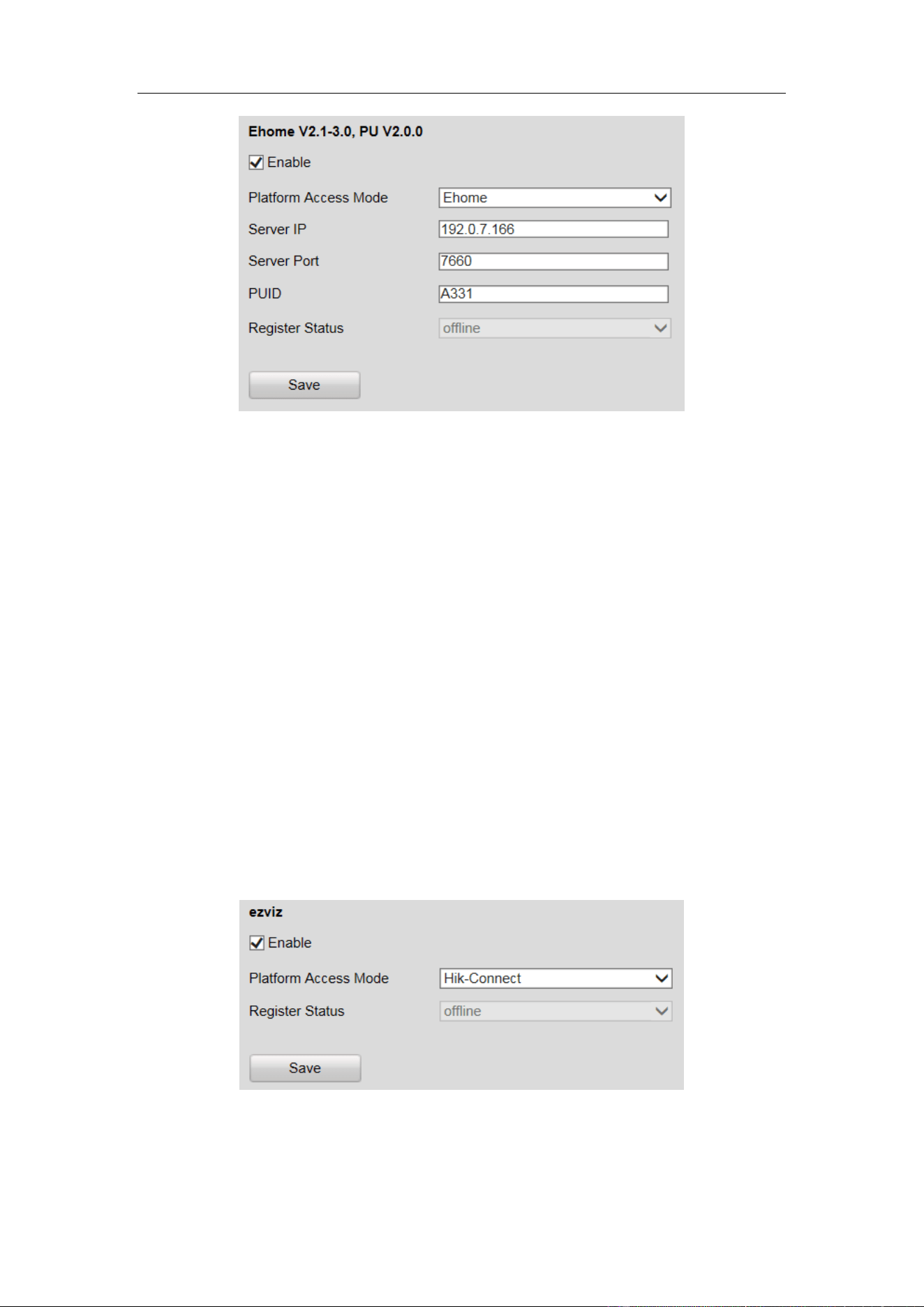
Guidance Terminal User Manual
49
Figure 4-43 Get Access to Ehome
4. Enter the Server IP, Server Port, and PUID.
5. Click Save to save the settings.
6. Reboot the guidance terminal to take the settings into effect. Then you can view
the Register Status to see if the terminal is accessed to Ehome successfully.
Accessing to Hik-Connect
Hik-Connect is a micro-video service platform. The guidance terminal can connect to
Hik-Connect to realize video/audio on demand, playback, etc.
Steps:
1. Go to Configuration > Remote Configuration > Platform Settings.
2. Check Enable checkbox.
3. Select the Platform Access Mode as Hik-Connect.
Figure 4-44 Get Access to Hik-Connect
4. Click Save to save the settings.
Guidance Terminal User Manual
50
5. Reboot the guidance terminal to take the settings into effect. Then you can view
the Register Status to see if the terminal is accessed to Hik-Connect successfully.
If the status is online, register the Hik-Connect account, and add the terminal to
Hik-Connect.
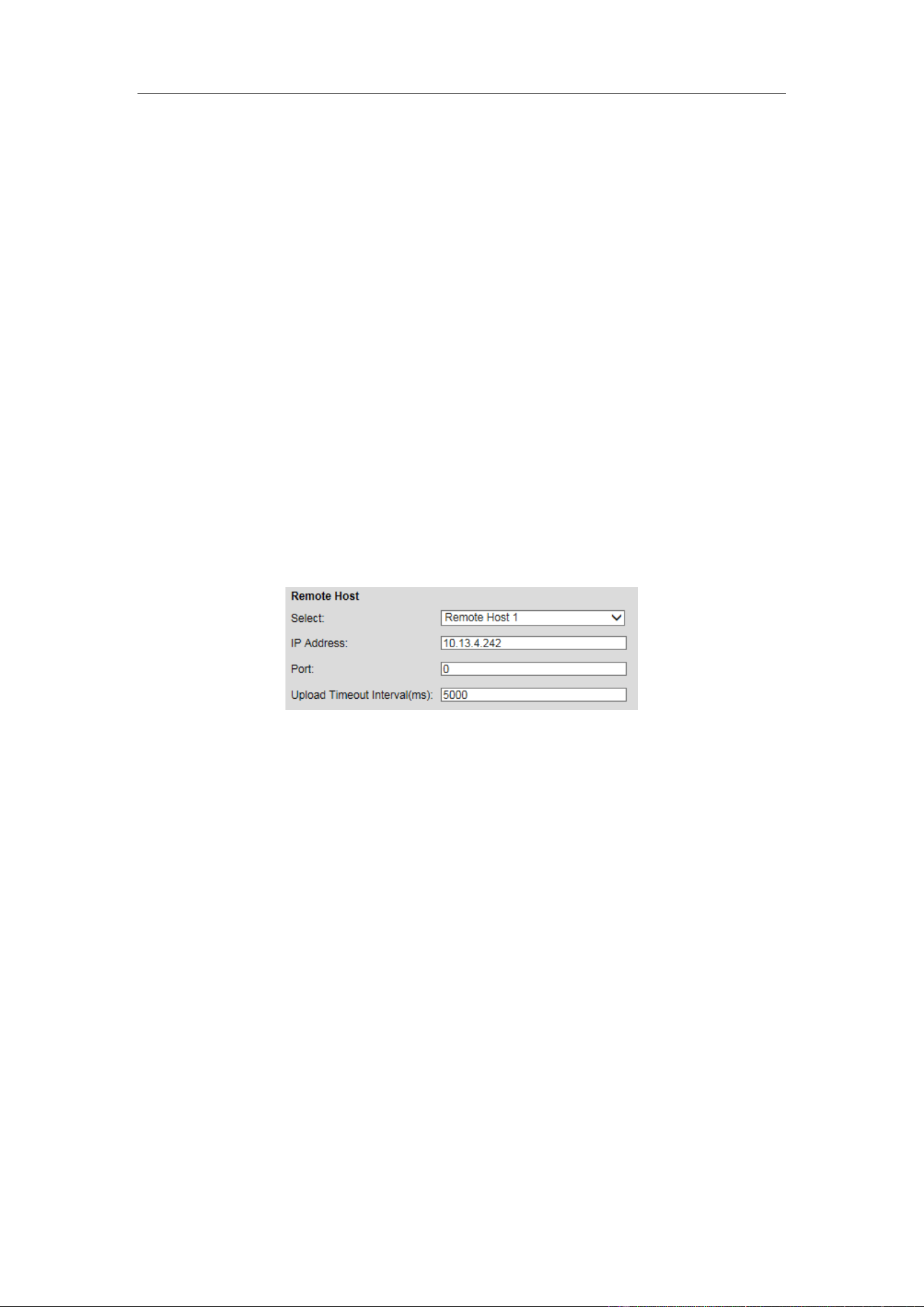
4.2.14 Configuring Remote Host
You can set the remote host parameters for the data uploading in the Remote Host
interface.
Steps:
1. Select the remote host from the drop-down list.
2. Enter the IP Address, Port and Uploading Timeout Interval.
3. Click Save to save the settings.
Figure 4-45 Remote Host
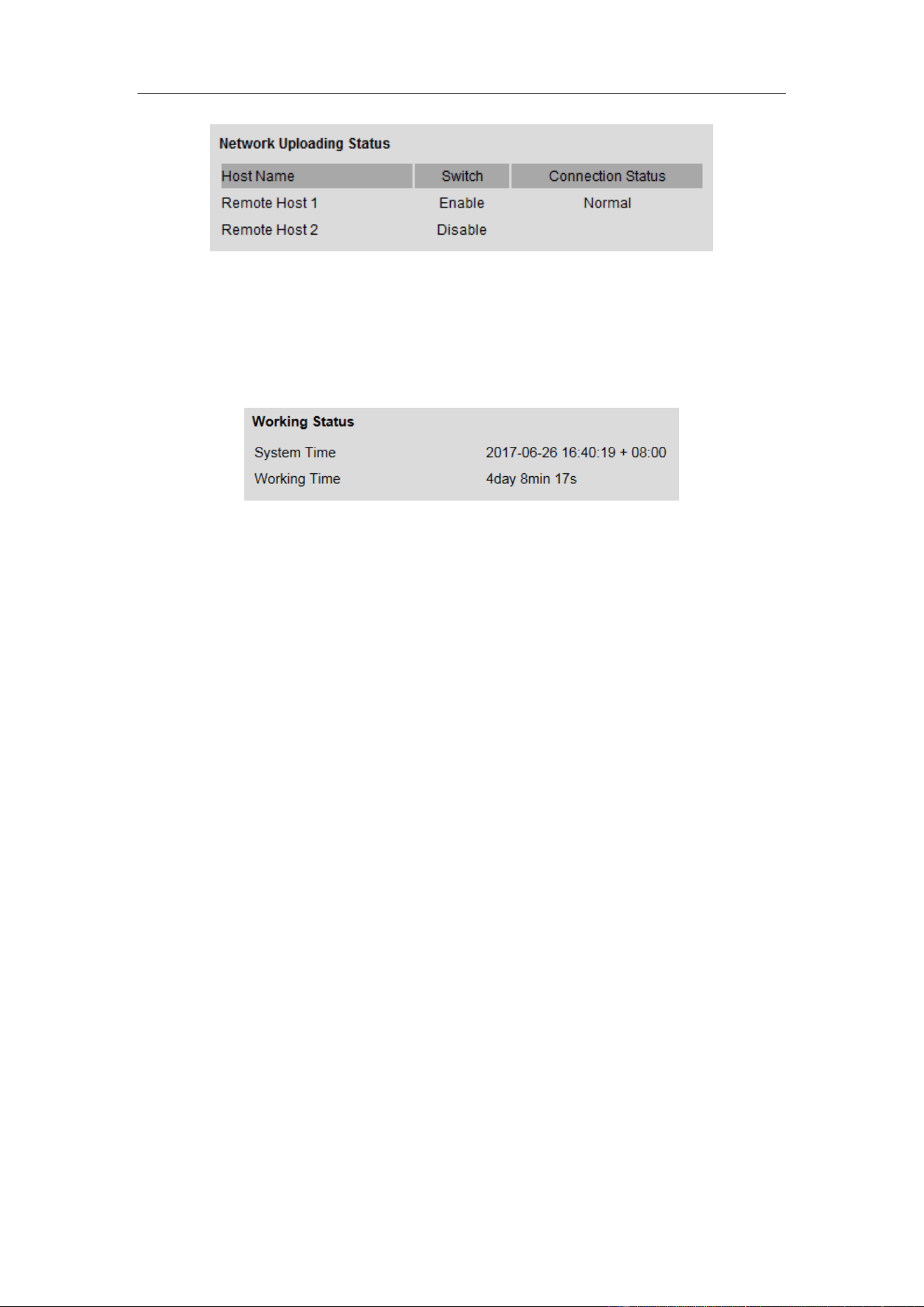
4.2.15 Viewing Status
You can view the system status in Status interface.
Viewing Network Uploading Status
You can view the network uploading status to find out if the remote host is enabled. If
the status is Disable, you should check if the IP address and other parameters are
correctly configured in Remote Host interface.
Guidance Terminal User Manual
51
Figure 4-46 Uploading Status
Viewing Working Status
You can view the system time and working time in Working Status interface.
Figure 4-47 Working Status
Guidance Terminal User Manual
52
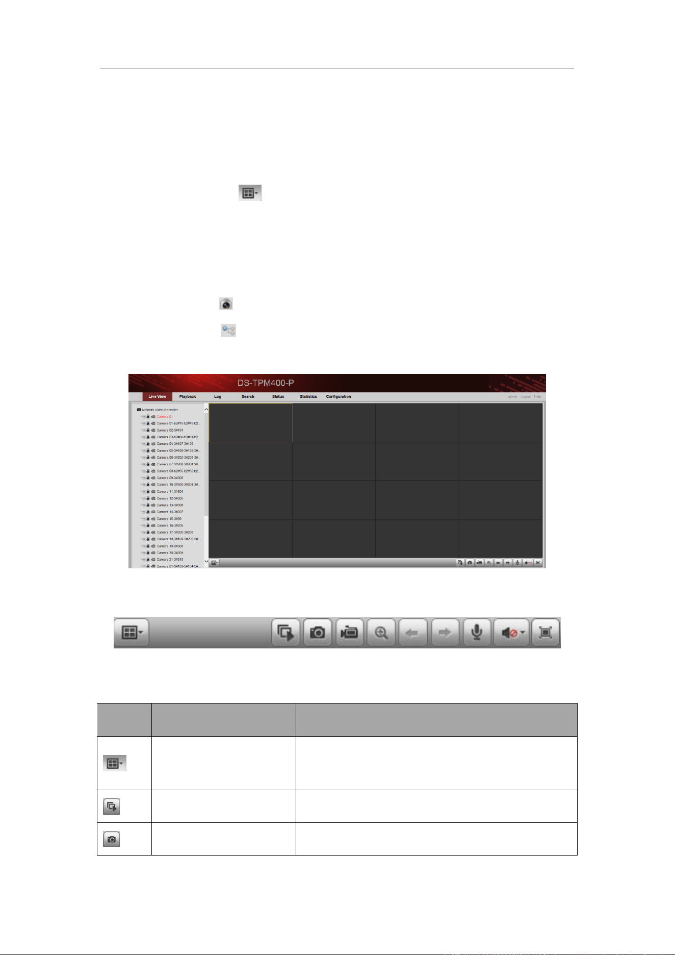
Chapter 5 Live View
Steps:
1. Open the Live View page.
2. (Optional) Click the icon in the live view toolbar, and select the screen
layout mode.
3. Double-click the camera name after selecting the display window to start the live
view.
Or you can click before the camera name to start the live view.
4. (Optional) Click before the camera name to select the main stream or sub
stream.
Figure 5-1 Live View Interface
Live View Toolbar:
Figure 5-2 Toolbar
On the Live View page, the following toolbar buttons are available:
Icon
Name
Description
Set View
Set the screen layout mode. 4 types of screen
layout modes are selectable: 1-Screen, 4-Screen,
9-Screen and 16-Screen.
Start All Live View
Start the live view of all cameras.
Capture
Capture the picture in the live view process.

Guidance Terminal User Manual
53
Start All Recording
Start the recording of all cameras.
Prev Page
Go for live view of the previous page.
Next Page
Go for live view of the next page.
Start Two-way Audio
Enable the two-way audio.
Audio On/Audio Off
Turn on/off the audio in live view
Full Screen
Display the live view in full screen mode. Press
ESC to exit.
Guidance Terminal User Manual
54
Chapter 6 Playback
Purpose:
The record files stored on the HDDs on the local device can be searched and played
back remotely through the web browser.
Click the Playback tab to enter the Playback interface.
6.1 Playback Interface
The Playback interface is shown as follows.
Figure 6-1 Playback Interface
Playback Toolbar:
Figure 6-2 Playback Toolbar
On the Playback page, the following toolbar buttons are available:
Table 6-1 Toolbar Description
Icon
Name
Description
Set View
Set the screen layout mode. 4 types of screen
layout modes are selectable: 1-Screen, 4-Screen,
9-Screen and 16-Screen.
Stop Playback
Stop the playback of the record files.
Slow Forward
Decrease the playback speed of the record files.
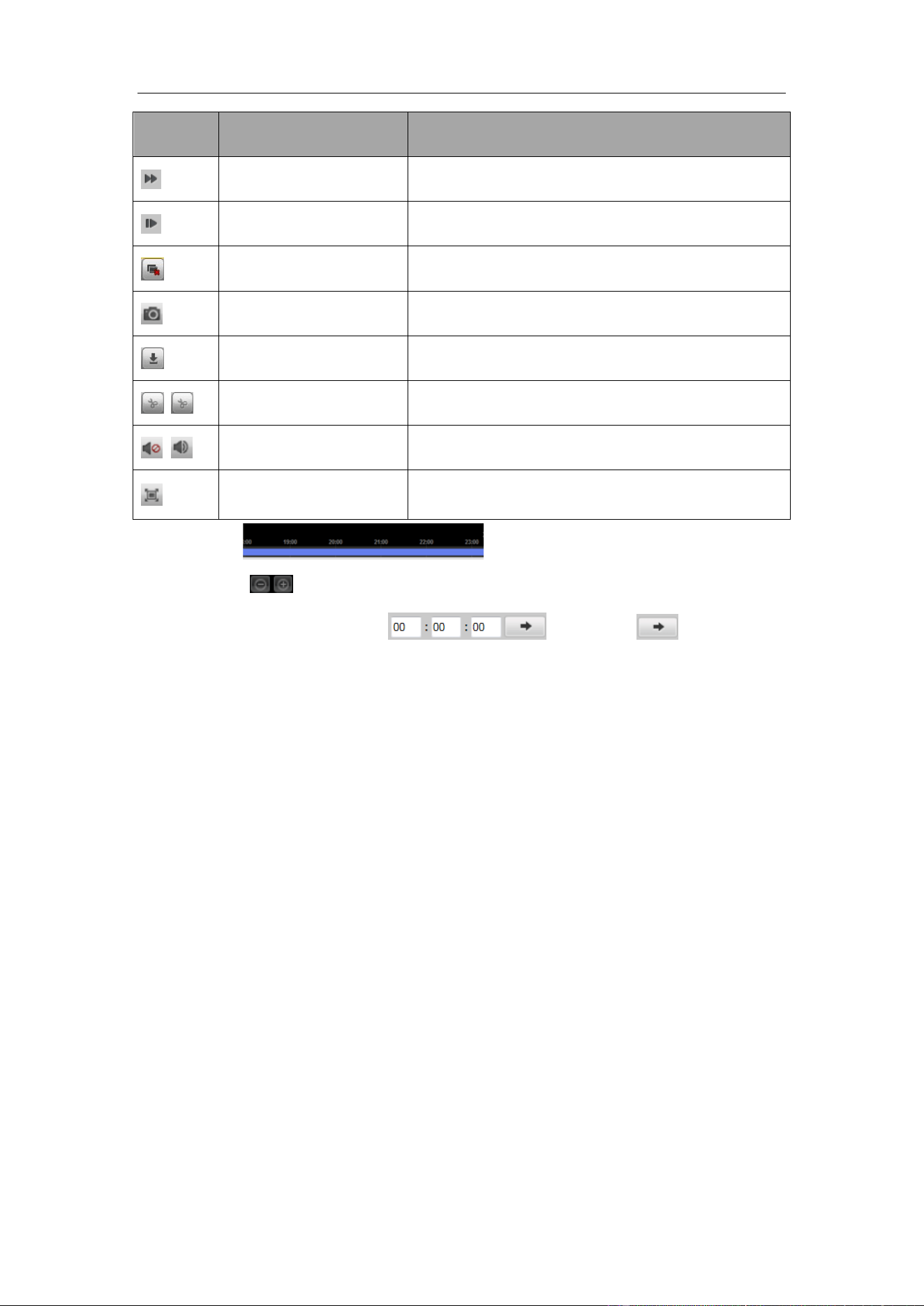
Guidance Terminal User Manual
55
Icon
Name
Description
Fast Forward
Increase the playback speed of the record files.
Single Frame
Play back the record files frame by frame.
Stop All Playback
Stop the playback of all the cameras.
Capture
Capture the picture in the playback process.
Download
Download the record file for backup.
Start/Stop Clipping
Start/Stop clipping the record files.
Audio On/Audio Off
Turn on/off the audio in live view
Full Screen
Display the playback in full screen mode. Press
ESC to exit.
Click on the to select the time and play the record.
You can click to zoom out or zoom in on the timeline.
You can input the time in the and click to go to the
specified time to view the record.
6.2 Searching Record Files
Steps:
1. Open the Playback page.
2. Select the cameras to be searched from the list.
3. Select the date on the calendar for the search.
4. Click Search.

Guidance Terminal User Manual
56
Chapter 7 Log
Purpose:
You can view and export the log files at any time, including operation, alarm,
exception and information of device.
Before you start:
The Log function can be realized only when the device is connected with HDD or
network disk.
Click Log tab to entre the Log interface.
Figure 7-1 Log Interface
7.1 Searching Log Files
Steps:
1. Open the Log Search page.
2. Select the Major Type. There are four major types, including Alarm, Exception,
Operation and Information. You can also select All Types to search all types of
the log.
3. Select the Minor Type.
4. Click to specify the Start Time and End Time.
5. Click Search. The log files between the start time and end time will be displayed
on the list.

Guidance Terminal User Manual
57
6. (Optional) You can click to save the searched logs.
Please narrow the time range or filter the log type for search if there are too many log
files.
Guidance Terminal User Manual
58
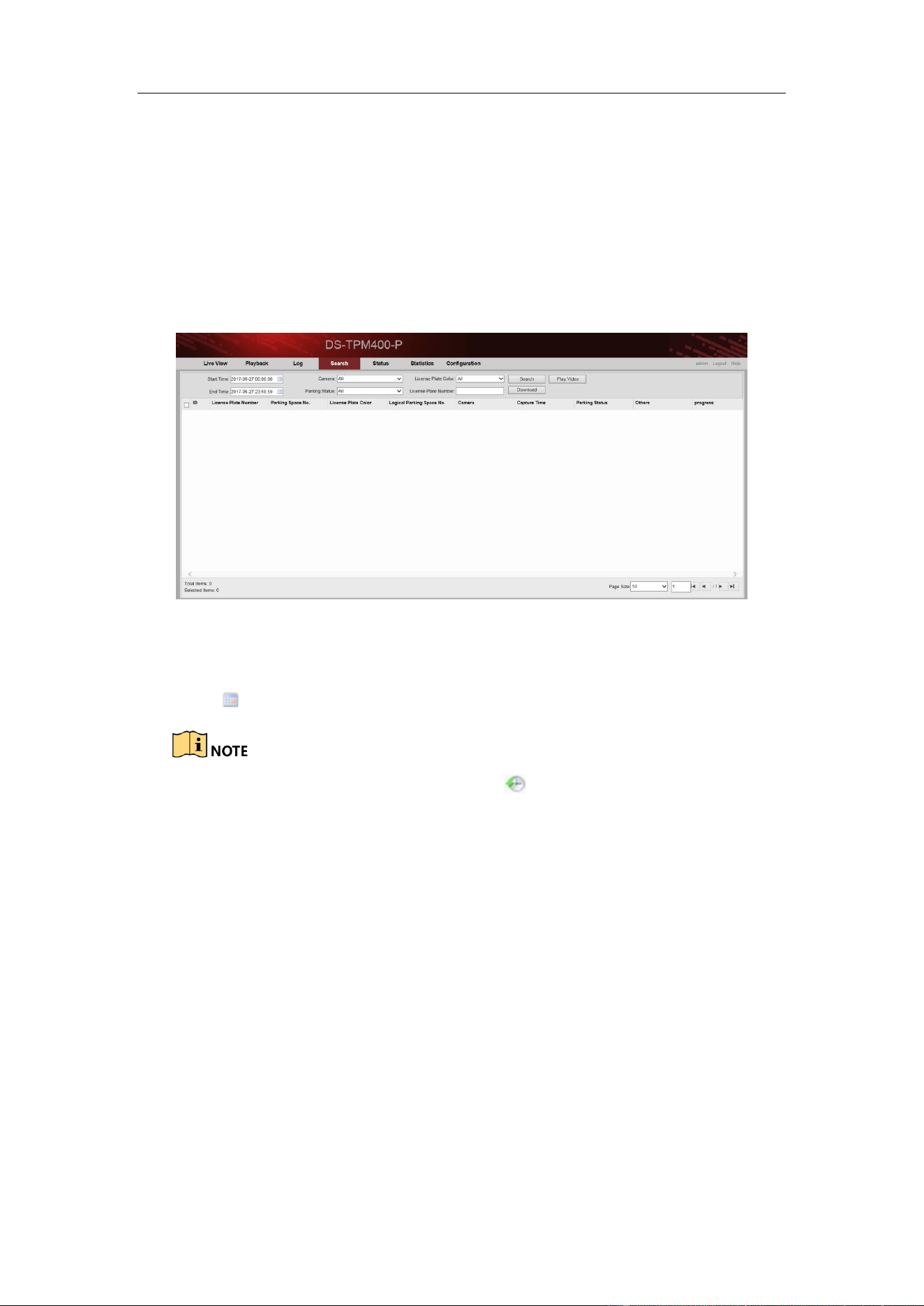
Chapter 8 Data Search
Purpose:
You can search the data such as the license plate number, parking space number, etc.
by specifying the search condition in Search interface.
Click the Search tab to enter the Search interface.
Figure 8-1 Search Interface
Steps:
1. Click to specify the Start Time and End Time.
When inputting the time, you can click for quick selection.
Time range cannot exceed 7 days.
2. Select the Camera from the drop-down list.
3. Select Parking Status from the drop-down list.
4. Select License Plate Color from the drop-down list.
5. (Optional) You can enter the License Plate Number for detailed search.
6. Click Search.
Guidance Terminal User Manual
59
Chapter 9 Status
Purpose:
You can view the status of the current working cameras as well as the parking space
status.
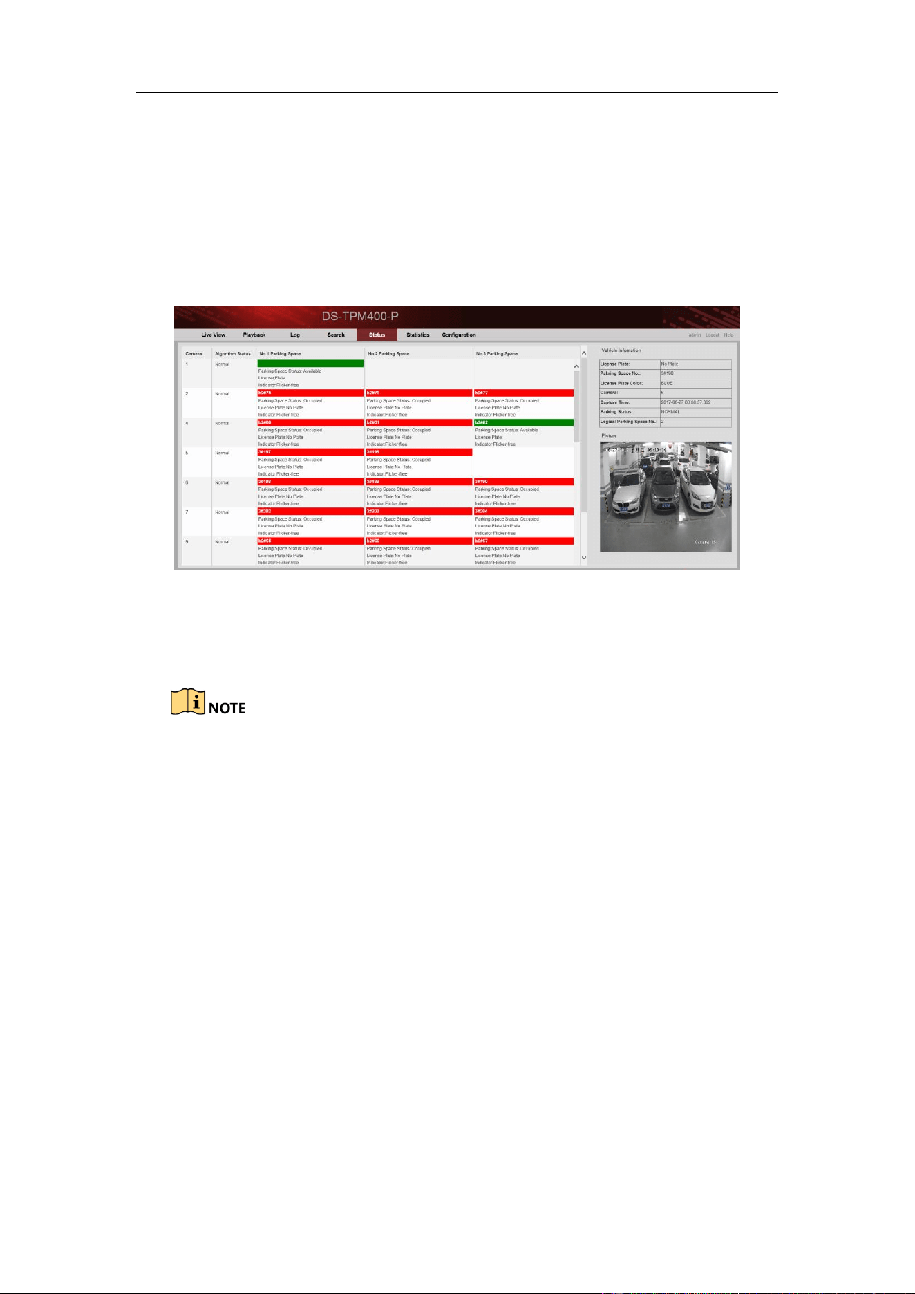
Click Status tab to enter the Status interface.
Figure 9-1 Status Interface
You can view the camera working status, the parking space information including
parking space status, liscence plate, etc.
There are two colors of the parking space box. Green means the parking
space is free. Red means the parking space is occupied.
If the colour of parking space box on the interface and the colour of the
parking space light is the same, the parking space is occupied by a car.
Every camera has three parking space lights and every light is related to one
parking space. If only one light is connected to the camera, other two parking
spaces are free.
If the parking space box on the interface is coloured, click it and you can
view vehicle information and picture on the right part of the interface as
follows.
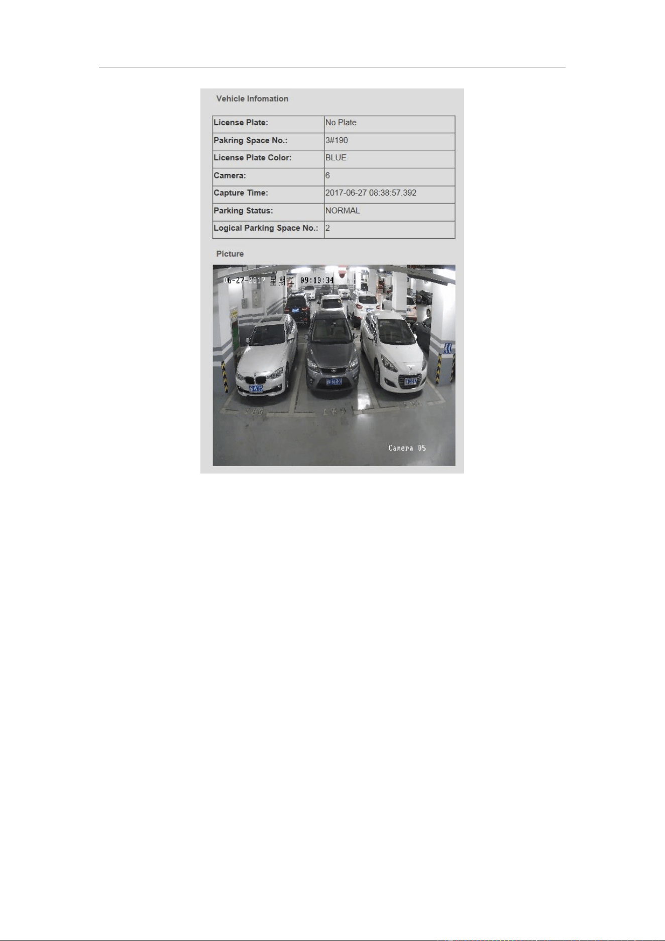
Guidance Terminal User Manual
60
Figure 9-2 Vehicle Information

Guidance Terminal User Manual
61
Chapter 10 Statistics
Purpose:
You can view the statistics of parking space information and LED guidance screen
information in Statistics interface.
Click Statistics tab to enter the Statistics interface.
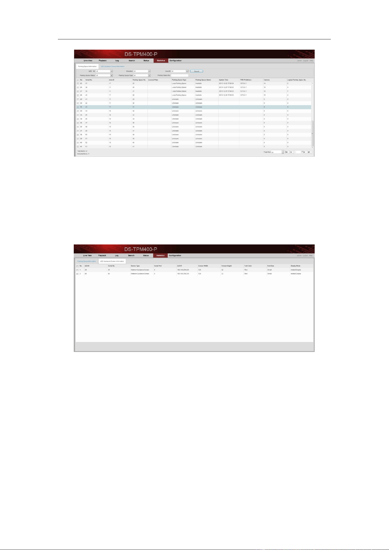
10.1 Viewing Parking Space Information
You can view all the parking space information in Parking Space Information tab.
Or you can input the following search condition and click Search to search the
specified parking space.
Parking spaces may include local parking spaces or other parking spaces on the
guidance terminal. This interface shows offline statistics.
LED ID: LED ID is the index of external LED.
Direction: Every LED may access to multiple directions.
Area ID: The area is related to every direction and contains multiple parking
spaces.
Parking Space Status: Camera offline and network exception may cause
parking space unknown.
Parking Space Type: Camera offline and network exception may cause
parking space unknown.
Parking Space No.: Parking space information can be searched according to
parking space number.
Guidance Terminal User Manual
62
Figure 10-1 Parking Space Information Statisctics
10.2 Viewing LED Guidance Screen Information
You can view all the LED guidance screen information in LED Guidance Screen
Information tab.
Figure 10-2 LED Guidance Screen Information Statisctics
0300021070914

0
UD07327B-A