
0
Intelligent Driving Assistance Terminal
User Manual

Intelligent Driving Assistance Terminal • User Manual
I
Legal Information
© 2022 Hangzhou Hikvision Digital Technology Co., Ltd. All rights reserved.
About this Manual
The Manual includes instructions for using and managing the Product. Pictures, charts, images and all other information
hereinafter are for description and explanation only. The information contained in the Manual is subject to change,
without notice, due to firmware updates or other reasons. Please find the latest version of this Manual at the Hikvision
website (https://www.hikvision.com/).
Please use this Manual with the guidance and assistance of professionals trained in supporting the Product.
Trademarks
and other Hikvision’s trademarks and logos are the properties of Hikvision in various jurisdictions.
Other trademarks and logos mentioned are the properties of their respective owners.
Disclaimer
TO THE MAXIMUM EXTENT PERMITTED BY APPLICABLE LAW, THIS MANUAL AND THE PRODUCT DESCRIBED, WITH ITS
HARDWARE, SOFTWARE AND FIRMWARE, ARE PROVIDED “AS IS” AND “WITH ALL FAULTS AND ERRORS”. HIKVISION
MAKES NO WARRANTIES, EXPRESS OR IMPLIED, INCLUDING WITHOUT LIMITATION, MERCHANTABILITY, SATISFACTORY
QUALITY, OR FITNESS FOR A PARTICULAR PURPOSE. THE USE OF THE PRODUCT BY YOU IS AT YOUR OWN RISK. IN NO
EVENT WILL HIKVISION BE LIABLE TO YOU FOR ANY SPECIAL, CONSEQUENTIAL, INCIDENTAL, OR INDIRECT DAMAGES,
INCLUDING, AMONG OTHERS, DAMAGES FOR LOSS OF BUSINESS PROFITS, BUSINESS INTERRUPTION, OR LOSS OF DATA,
CORRUPTION OF SYSTEMS, OR LOSS OF DOCUMENTATION, WHETHER BASED ON BREACH OF CONTRACT, TORT
(INCLUDING NEGLIGENCE), PRODUCT LIABILITY, OR OTHERWISE, IN CONNECTION WITH THE USE OF THE PRODUCT,
EVEN IF HIKVISION HAS BEEN ADVISED OF THE POSSIBILITY OF SUCH DAMAGES OR LOSS.
YOU ACKNOWLEDGE THAT THE NATURE OF THE INTERNET PROVIDES FOR INHERENT SECURITY RISKS, AND HIKVISION
SHALL NOT TAKE ANY RESPONSIBILITIES FOR ABNORMAL OPERATION, PRIVACY LEAKAGE OR OTHER DAMAGES
RESULTING FROM CYBER-ATTACK, HACKER ATTACK, VIRUS INFECTION, OR OTHER INTERNET SECURITY RISKS; HOWEVER,
HIKVISION WILL PROVIDE TIMELY TECHNICAL SUPPORT IF REQUIRED.
YOU AGREE TO USE THIS PRODUCT IN COMPLIANCE WITH ALL APPLICABLE LAWS, AND YOU ARE SOLELY RESPONSIBLE
FOR ENSURING THAT YOUR USE CONFORMS TO THE APPLICABLE LAW. ESPECIALLY, YOU ARE RESPONSIBLE, FOR USING
THIS PRODUCT IN A MANNER THAT DOES NOT INFRINGE ON THE RIGHTS OF THIRD PARTIES, INCLUDING WITHOUT
LIMITATION, RIGHTS OF PUBLICITY, INTELLECTUAL PROPERTY RIGHTS, OR DATA PROTECTION AND OTHER PRIVACY
RIGHTS. YOU SHALL NOT USE THIS PRODUCT FOR ANY PROHIBITED END-USES, INCLUDING THE DEVELOPMENT OR
PRODUCTION OF WEAPONS OF MASS DESTRUCTION, THE DEVELOPMENT OR PRODUCTION OF CHEMICAL OR
BIOLOGICAL WEAPONS, ANY ACTIVITIES IN THE CONTEXT RELATED TO ANY NUCLEAR EXPLOSIVE OR UNSAFE NUCLEAR
FUEL-CYCLE, OR IN SUPPORT OF HUMAN RIGHTS ABUSES.
IN THE EVENT OF ANY CONFLICTS BETWEEN THIS MANUAL AND THE APPLICABLE LAW, THE LATTER PREVAILS.

Intelligent Driving Assistance Terminal • User Manual
I
Regulatory Information
FCC Information
Please take attention that changes or modification not expressly approved by the party responsible
for compliance could void the user’s authority to operate the equipment.
FCC Compliance
This equipment has been tested and found to comply with the limits for a Class A digital device,
pursuant to part 15 of the FCC Rules. These limits are designed to provide reasonable protection
against harmful interference when the equipment is operated in a commercial environment. This
equipment generates, uses, and can radiate radio frequency energy and, if not installed and used in
accordance with the instruction manual, may cause harmful interference to radio communications.
Operation of this equipment in a residential area is likely to cause harmful interference in which
case the user will be required to correct the interference at his own expense.
FCC Conditions
This device complies with part 15 of the FCC Rules. Operation is subject to the following two
conditions:
1. This device may not cause harmful interference.
2. This device must accept any interference received, including interference that may cause
undesired operation.
EU Conformity Statement
This product and - if applicable - the supplied accessories too are marked with "CE" and
comply therefore with the applicable harmonized European standards listed under the
EMC Directive 2014/30/EU, the LVD Directive 2014/35/EU, the RoHS Directive 2011/65/EU.
2012/19/EU (WEEE directive): Products marked with this symbol cannot be disposed of as
unsorted municipal waste in the European Union. For proper recycling, return this product
to your local supplier upon the purchase of equivalent new equipment, or dispose of it at
designated collection points. For more information see: www.recyclethis.info
2006/66/EC (battery directive): This product contains a battery that cannot be disposed
of as unsorted municipal waste in the European Union. See the product documentation
for specific battery information. The battery is marked with this symbol, which may include
lettering to indicate cadmium (Cd), lead (Pb), or mercury (Hg). For proper recycling, return the
battery to your supplier or to a designated collection point. For more information see:
www.recyclethis.info
Industry Canada ICES-003 Compliance
This device meets the CAN ICES-3 (A)/NMB-3(A) standards requirements.

Intelligent Driving Assistance Terminal • User Manual
II
Symbol Conventions
The symbols that may be found in this document are defined as follows.
Safety Instructions
Proper configuration of all passwords and other security settings is the responsibility of the
installer and/or end-user.
In the use of the product, you must be in strict compliance with the electrical safety
regulations of the nation and region. Please refer to technical specifications for detailed
information.
Input voltage should meet both the SELV (Safety Extra Low Voltage) and the Limited Power
Source with 100 to 240 VAC or 12 VDC according to the IEC60950-1 standard. Please refer to
technical specifications for detailed information.
Do not connect several devices to one power adapter as adapter overload may cause over-
heating or a fire hazard.
Please make sure that the plug is firmly connected to the power socket.
If smoke, odor or noise rise from the device, turn off the power at once and unplug the power
cable, and then please contact the service center.
Symbol
Description
Provides additional information to emphasize or supplement
important points of the main text.
Indicates a potentially hazardous situation, which if not avoided,
could result in equipment damage, data loss, performance
degradation, or unexpected results.
Indicates a hazard with a high level of risk, which if not avoided, will
result in death or serious injury.

Intelligent Driving Assistance Terminal • User Manual
III
TABLE OF CONTENTS
Chapter 1 Introduction ................................................................................................................... 1
Product Overview .......................................................................................................................................... 1
Key Feature.................................................................................................................................................... 1
1.2.1 Abnormal Detection ............................................................................................................................ 1
1.2.2 ADAS ................................................................................................................................................... 2
1.2.3 BSD ..................................................................................................................................................... 4
Chapter 2 Packing List and Appearance.......................................................................................... 5
Packing List .................................................................................................................................................... 5
Front Panel .................................................................................................................................................... 5
Rear Panel ..................................................................................................................................................... 6
Chapter 3 Installation ..................................................................................................................... 8
Preparation .................................................................................................................................................... 8
3.1.1 Installation Environment ..................................................................................................................... 8
3.1.2 Installation Safety Instructions ............................................................................................................. 9
3.1.3 Tools for Installation ............................................................................................................................ 9
Device Installation.......................................................................................................................................... 9
3.2.1 Insert SIM Card and SD Card ................................................................................................................ 9
3.2.2 Fix the Device .....................................................................................................................................10
3.2.3 Install Antenna ...................................................................................................................................10
Chapter 4 Wiring .......................................................................................................................... 12
I/O Wiring .....................................................................................................................................................12
Power Wiring ................................................................................................................................................12
Power Up and Check Device ..........................................................................................................................13
Chapter 5 APP Operation ............................................................................................................. 15
Install the Calibration App .............................................................................................................................15
ADAS Calibration ...........................................................................................................................................16
5.2.2 Calibration Pole Method .....................................................................................................................18
5.2.3 Disappearance Line Method ...............................................................................................................19
Abnormal Detection and BSD Camera Parameters .........................................................................................20
5.3.1 Configure Parameters for Abnormal Detection Camera .......................................................................20
5.3.2 Configure Parameters of BSD Camera .................................................................................................22
IPC Support ...................................................................................................................................................27
5.4.1 Add IPC ..............................................................................................................................................27
5.4.2 Delete IPC ..........................................................................................................................................28
Device Calibration .........................................................................................................................................31
5.5.1 Format the Storage.............................................................................................................................31
5.5.2 Configure the Platform Parameters ....................................................................................................31
5.5.3 Update the Device by SD Card ............................................................................................................32
5.5.4 Display Output Configuration..............................................................................................................33
Intelligent Driving Assistance Terminal • User Manual
1
Chapter 1 Introduction
Product Overview
Intelligent driving assistance terminal (abbreviated as intelligent terminal) integrates forward car
leaving detection, abnormal detection, and right side blind spot vehicle discern system (optional).
Based on the deep-learning algorithm, the device can precisely warn against various kinds of
situations with timely video and audio warning to inform the driver of the potential danger and to
drive in a safer way.
Due to its unique features, this intelligent terminal adapts to most weather conditions and can be
widely deployed on commercial vehicles, such as bus, truck, industrial vehicle, and vehicle carrying
dangerous chemicals.
Key Feature
The device supports various kinds of event-triggered detection. When an event occurs, it can
release warning sound, capture and record relevant event. The device also supports exporting
images and recordings by SD card for accident investigation.
You need to set warning parameter, capture, and recording function of device with dedicated
app.
The device only serves as driving assistance system to improve driving safety and you cannot
solely rely on the device for driving. Drivers should be responsible for driving safety.
The prerequisite of uploading to the platform is that the terminal should support 3G/4G dial
and can connect to the platform.
Abnormal Detection can detect risky driving behaviors and trigger alarm.
Fatigued Driving Detection Warning
When detecting driver dozing off during driving, the device triggers audio alarm.
Sight Detection Warning
When the driver does not focus on the road and display unsafe behaviors such as tilting head
down to look at the phone, glancing around or looking into mirror and doing makeup during
driving, the device triggers audio alarm.
Smoking Detection Warning
When the driver smokes during driving, the device triggers audio alarm.
Phone Call Detection Warning
When the driver answers the phone during driving, the device triggers audio alarm.

Intelligent Driving Assistance Terminal • User Manual
2
Seatbelt Not Fasten Detection Warning
When the seatbelt of the driver is not fasten, the device triggers audio alarm.
IR Interrupting Sunglasses Detection
When the driver puts on the sunglass that interrupts the infrared for a period of time, the
device triggers audio alarm, for this would tamper the function of the Abnormal Detection.
ADAS (Advanced Driving Assistance System) can detect driving environment, warn against potential
danger, and upload the corresponding information to the platform.
ADAS Warning Type Description
Event
Prerequisite
Warning
No Warning
Forward
Collision
Warning (FCW)
The vehicle speed is
between 0 and 120
km/h and FCW is
enabled (triggered).
I degree alarm is
triggered when the
speed is within 30 km/h
to 50 km/h.
II degree alarm o is
triggered when the
speed is over 50 km/h.
When your vehicle drives
faster than the front vehicle
where collision may occur,
the terminal will release
warning.
The warning will be released
no earlier than 4 s.
Bad weather with low
visibility, such as heavy
fog and heavy rain.
Vehicles with special
shapes.
The vehicle speed is
lower than 30 km/h or
the set value.
FCW is disabled.

Intelligent Driving Assistance Terminal • User Manual
3
Lane Departure
Warning (LDW)
The vehicle speed is
higher than 30 km/h
and HMW is enabled.
I degree alarm is
triggered when the
speed is within 30 km/h
to 50 km/h.
II degree alarm o is
triggered when the
speed is over 50 km/h.
When the vehicle is deviating
from the lane, the terminal
will release warning.
Turning signal is on
when the vehicle is
changing lane or hazard
warning lamps are on.
There is no lane line on
the road or the lane line
is not clear.
The vehicle speed is
lower than 30 km/h or
the set value...
Bad weather with low
visibility, such as heavy
fog and heavy rain.
LDW is disabled.
Headway
Monitoring
Warning
(HMW)
The vehicle speed is
higher than 30 km/h
and HMW is enabled.
I degree alarm is
triggered when the
speed is within 30
km/h to 50 km/h.
II degree alarm o is
triggered when the
speed is over 50 km/h.
When TDC (Time to
Collision) is shorter than
0.8 s, the terminal will
release warning.
When TDC (Time to
Collision) is less than both
0.8 s and the set value,
the terminal will not
release warning
repeatedly until the
interval is 1.5 times larger
than the set value. HWM
will refresh automatically
and upload warning
information to the
platform.
The vehicle speed is
lower than 30 km/h or
the set value.
Bad weather with low
visibility, such as heavy
fog and heavy rain.
HMW is disabled.

Intelligent Driving Assistance Terminal • User Manual
4
Pedestrian
Collision
Warning (PCW)
The vehicle speed is
between 1 km/h and
50 km/h and PCW is
enabled (triggered).
I degree alarm is
triggered when the
speed is under 20
km/h.
II degree alarm o is
triggered when the
speed is within 20
km/h to 50 km/h.
When there is potential
collision risk, the device will
release warning.
Night with low
visibility.
Pedestrian is shorter
than 0.8 m (2.6 ft.).
Bad weather with low
visibility, such as heavy
fog and heavy rain.
The vehicle speed is
higher than 50 km/h or
the set value.
PCW is disabled.
Sharp Turn
Warning
-
When the sharp turn
behavior occurs during
driving, the device will
release warning.
-
Right Side Blind
spot vehicle
Discern System
(R- BSD)
(Optional)
When the vehicle
speed is lower than 30
km/h and R-BSD is
enabled (triggered).
When motor vehicle, non-
motor vehicle, or
pedestrians are detected
among the right side blind
spot of the vehicle, the
intelligent will release
warning.
Incorrect blind spot
settings.
Camera image error.
BSD is disabled.
BSD (Blind Spot Detection) can trigger high frequency voice or light alarm when it detects vehicles,
pedestrians, bicycles and tricycles that enter the right side blind spot of the truck or bus. The alarm
will stop when these objects leave the alarm zone.
Filter the non-attended zone warning
BSD will not alarm for the object that is in the traffic island, bus station, crossing road, and
green belt.
Send alarm based on the tendency of movement of the object vehicle
BSD will send alarm when the object vehicle move in the same direction of the current vehicle
and tends to over take.

Intelligent Driving Assistance Terminal • User Manual
5
Chapter 2 Packing List and Appearance
Packing List
After receiving the product, first check the integrity of the product package, and then open the
package to check whether all the accessories shown in Table 2-1 Packing List are included.
Packing List
No.
Picture for Illustration
Name
Quantity
1
Intelligent Driving Assistance
Terminal
1
2
Main Bundle
1
3
Screw Package
1
4
Panel Key
1
5
GPS Antenna (Only for the
device which supports GPS
function)
1
6
3G/4G Antenna (Only for the device
which supports dial function)
1
Front Panel
Insert the panel key and switch it to the unlocking position to open the front panel. Interfaces on
front panel are shown in Figure 2-1 and the corresponding functions are described in Table 2-2.

Intelligent Driving Assistance Terminal • User Manual
6
Front Panel
Interfaces Description (Front Panel)
Name
Description
Indicator Light
Power:
Solid red: the device is powered on.
Status:
Solid green: ADAS works properly.
Fast flashing: exception occurs.
SIM Card Slot
Dial to connect to network after inserting SIM card.
USB Interface
Calibrate the Device.
SD Card Slot
Insert SD card for local storage.
Rear Panel
Interfaces on rear panel are shown in Figure 2-2 and their corresponding functions are described in
Table 2-3.
Interfaces on rear panel may vary by model. Please refer to the actual model. This manual
illustrates all the interfaces which can be found on different device models.

Intelligent Driving Assistance Terminal • User Manual
7
Rear Panel
Interfaces Description (Rear Panel)
Name
Description
Four-core Aviation Plug 4
Connects to mobile camera.
Four-core Aviation Plug 3
Connects to mobile BSD camera.
Four-core Aviation Plug 2
Connects to mobile Abnormal Detection camera.
Four-core Aviation Plug 1
Connects to mobile ADAS camera.
RS-485
Reserved.
I/O Interface
Connects to main bundle. Refers to Chapter 4 Wiring for
details.
GPS Antenna Interface
Connects to GPS antenna and GPS device.
3G/4G Antenna Interface
M-ANT. Connects to 3G/4G antenna.

Intelligent Driving Assistance Terminal • User Manual
8
Chapter 3 Installation
Preparation
Disconnect the power when you assemble, disassemble, or wire the device. DO NOT operate when
the power is on to avoid safety hazards.
Before installation, take out the device from the package and check whether the device and
accessories are included and whether they are damaged. Refer to Section 2.1 Packing List for
accessories checking.
This manual takes one type of various devices as an example for installation illustration. Devices
may vary from each other in appearance and size. Please refer to the actual device.
Before installation, you need to select an appropriate installation location and arrange cable
routing to make sure the power and cables are safe and stable. Convenience and rationality should
also be considered.
Select the location where the vehicle vibration is relatively weak (such as the rear space of the
driver seat or front passenger seat) and is away from the vehicle engine.
Make sure the intelligent terminal is away from the heat source of the vehicle and is installed on
the location with good ventilation for heat dissipation.
Due to the special heat dissipation feature of the intelligent terminal, please reserve enough
installation space for the device. The recommended space is illustrated in Figure 3-1.
Recommended Installation Space
Unit: mm (inch)

Intelligent Driving Assistance Terminal • User Manual
9
Place the device horizontally. Installing the device from any other angles may damage the
device.
Basic Requirements
Work related to electricity must be in strict compliance with the local electrical safety
regulations, fireproof regulations, and other relevant regulations.
Disconnect all the power related to the device during installation.
Cable Routing Requirements
The cable direction should be the same as the direction of original vehicle cables. Route cables
along the original cable slot of the vehicle and bundle them with the original cables.
Make sure the cable routing is neat and hidden.
Prepare anti-static gloves, cross screwdriver, and L-shape hex screwdriver.
Device Installation
Before you start
You need to purchase SD card and SIM Card in advance. Select the card according to your need.
SIM Card is used for dial-up Internet connection for the device.
SD card is used for local storage. After installation, the intelligent terminal can store data like
recordings, warning information, and captures in the SD card.
To use the SD card, it needs to be formatted first.
Wear anti-static gloves.
Insert panel key and rotate it to the unlocking position to open the front panel.
Intelligent Driving Assistance Terminal • User Manual
10
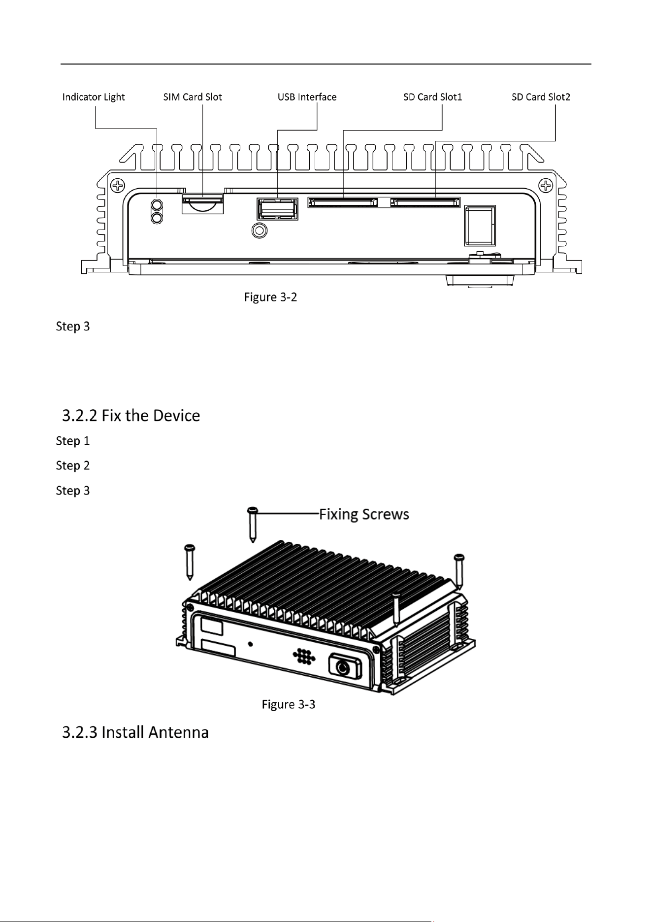
Interface Description
Insert cards.
Insert SIM card slowly into the SIM card slot.
Insert SD card slowly into the SD card slot and when you hear a click sound, the installation is
completed.
Drill holes on the vehicle according to the holes on the intelligent terminal.
Align the holes on both terminal and vehicle.
Fix the terminal on the vehicle with four fixing screws and the installation is completed.
Fix the Device
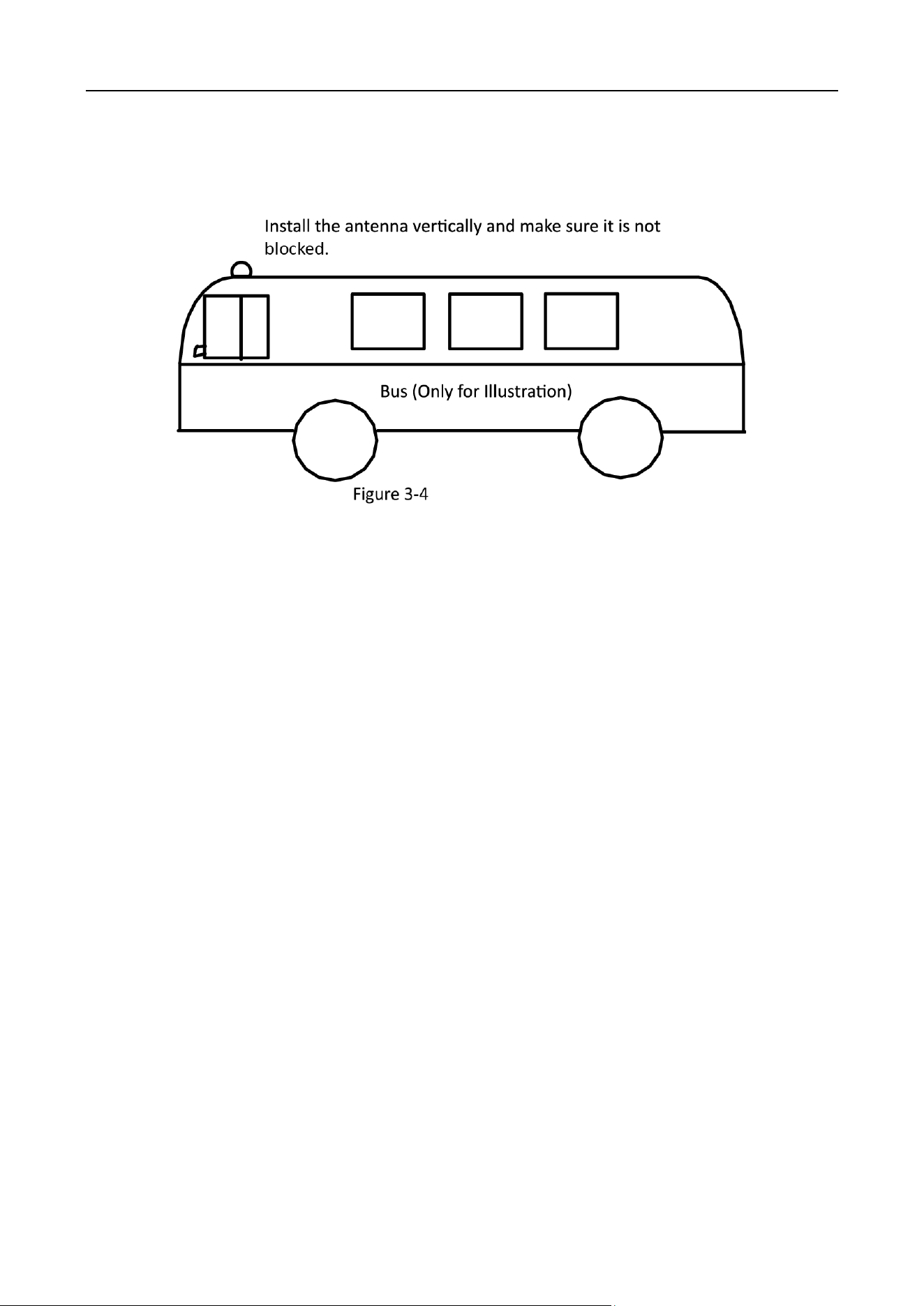
Install the 3G/4G antenna and GPS antenna on the appropriate location and connect the cables to
the corresponding interfaces.
Requirements:
Place the antenna vertically and make sure the signal receiving end faces up.
Intelligent Driving Assistance Terminal • User Manual
11
If the cable is too long, roll it into circle and bundle it to ensure signal receiving quality.
Install 3G/4G antenna on the non-metal object, such as windshield screen and seat back, and
make sure the antenna is 50 cm or farther away from the metal objects.
Install the Antenna
It is recommended to install the GPS antenna on the top of the vehicle, and connect the wire to
the antenna by punctuate a hole or through the gap of the door. In the former case, make sure
that hole is water tight.
If the GPS antenna has to be installed inside the vehicle due to special situations, the
requirements are as follows.
Install the antenna on the platform under the windshield screen.
Fix the antenna with neutral silicone sealant.
Adjust the antenna location to make sure signal quality.

Intelligent Driving Assistance Terminal • User Manual
12
Chapter 4 Wiring
I/O Wiring
After connecting to the main bundle, the I/O interface of the intelligent terminal can be connected to
the vehicle battery for power supply. Or it can be connected to signal, such as vehicle turning, to
collect driving information and store the information in the terminal.
Connect cables to their corresponding interfaces according to Figure 4-1 and Table 4-1.
Interface Description
I/O Interface Description
No.
Description
No.
Description
No.
Description
1
Power
2
Reserved
3
Reserved
4
ACC
5
Speed
6
Turn Left
7
Reserved
8
Buzzer+
9
Reserved
10
CAN+
11
Reserved
12
GND
13
Reserved
14
Reserved
15
Turn Right
16
Brake
17
Reserved
18
Buzzer-
19
Reserved
20
CAN-
-
-
Power Wiring
To ensure correct wiring, consult with the vehicle manufacturer about the connection method of
vehicle starter to avoid device damage resulted by mismatch.

Intelligent Driving Assistance Terminal • User Manual
13
The device supports ignition startup and the prerequisite is that the terminal power is connected to
the vehicle ignition starter.
Refer to Section 4.1 for interface description, find 1 (Power), 4 (ACC), 12(Ground) and connect them to
vehicle battery as shown in Figure 4-2.
Connect device power to the anode of vehicle constant power. Skip the main switch of vehicle
constant power.
Connect the ground interface of the device to the cathode of vehicle constant power.
Connect the AAC interface of the device to the vehicle ignition starter.
Power Wiring
The vehicle constant power refers to the master switch of vehicle power system. After flaming out, the
constant power can still supply direct current to devices in vehicle.
Power Up and Check Device
After completing the above installation steps, power the device up.
Observe the power status indicator: If the indicator is solid red, it means the device is powered up.

Intelligent Driving Assistance Terminal • User Manual
14
Insert panel key, rotate it to the locked position to lock the front panel. The installation is
completed.
The debugging and parameter configuration of the device is completed by professionals via dedicated
APP.
Before configuration, connect the APP to the intelligent terminal Wi-Fi. The SSID is ADAS-A4H-XXXX
(XXXX refers to the last four digits of the device serial No.) and the default password is 1234567890
Intelligent Driving Assistance Terminal • User Manual
15
Chapter 5 APP Operation
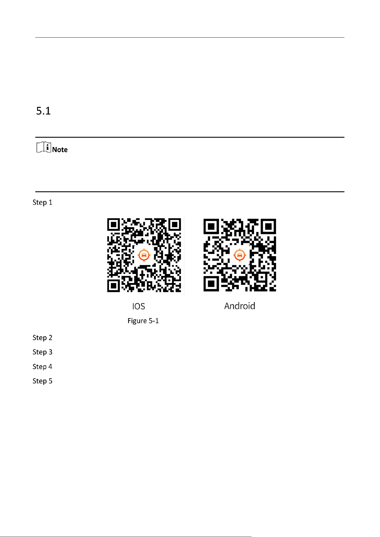
Install the Calibration App
Calibration is to set up the physical coordinate of the device for accurate algorithmic detection.
When installing the app, it is recommended to receive the technical support in setting up the
actual parameters for “place of installation”.
The user needs to apply for the account and password from headquarter.
Scan the following QR code in the following figure to download the calibration app.
QR Code for App Downloading
Connect the device to power supply and plugin the calibration module.
Open the app and connect the Wi-Fi name starting with ADAS
Enter the password: the password is 1234567890 by default.
Change the password to activate the device.

Intelligent Driving Assistance Terminal • User Manual
16
First Page
Connect the Wi-Fi with new password to enter the First Page.
ADAS Calibration
To calibrate ADAs camera, you need to enter the following parameters in the app:
the height of ADAS camera
the distances between ADAS camera and the outer edge of the two wheels
the distance between ADAS camera and the bumper
Tap Camera Setting on the ADAS Settings page.

Intelligent Driving Assistance Terminal • User Manual
17
Camera Settings on ADAS Settings
On the Camera Settings page, fill in the parameters.

Intelligent Driving Assistance Terminal • User Manual
18
Camera Parameters
Tap save to complete setting.
There are two methods to conduct the ADAS calibration: the calibration pole method and the
disappearance line method
Before You Start:
Prepare a calibration pole before calibration.
Place the calibration pole 1.5 m away from the front of the car at the middle. Make sure that
the calibration pole is vertical and at the same height with the camera.

Intelligent Driving Assistance Terminal • User Manual
19
The Position of the Calibration Pole
Open the side of the camera and adjust two black screws of the ADAS camera with a small
cross screwdriver. The visible one is for fixing the camera, and the deeper, non-visible one is
for calibrating the angle of camera. Make sure that the apex of the pole is within the yellow
rectangle.
Tap move in the app to adjust the horizontal line and vertical line, and make sure that they
coincide with the pole.
Save and tap Next.
Park the car along the middle line of the road with equal distance to each side. Make sure
that the road is even and the horizontal line is visible.
Adjust the black screw of the ADAS camera to calibrate its angle, and make sure that the
apex of the pole is within the yellow rectangle.
If due to the angle of the camera, the apex of the calibration pole cannot appear within the
yellow rectangle, then tap move in the app to adjust the horizontal line and vertical line until
they coincide with the pole.
Save and tap Next.

Intelligent Driving Assistance Terminal • User Manual
20
Abnormal Detection and BSD Camera Parameters
You can configure the parameters of Abnormal Detection and BSD according to your actual need.
On the First Page, 5 “Channels” are available. Channel 2 is for Abnormal Detection and Channel 3 is
for BSD. After choosing the channel you need, tap Channel Configuration.
In each of these configuration pages, you can choose whether to enable this channel and perform
the required function to send alarm. In addition, there are and 3 types of settings, among which
the Video Settings and Record Schedule Settings are the same for different channels.
On the First Page, choose Channel 2 and tap Channel Configuration to enter the Abnormal
Detection setting page.
Abnormal Detection Settings
Tap Abnormal Detection Setting to enter the setting page for parameters configuration.

Intelligent Driving Assistance Terminal • User Manual
21
Abnormal Detection Parameter Settings
Tap Save to enable your configuration.
Intelligent Driving Assistance Terminal • User Manual
22
On the Abnormal Detection Parameter Settings page, you can specify the behavior that will
trigger alarm, the specific way to store the capture and recording, the volume and sensitivity of
the alarm.
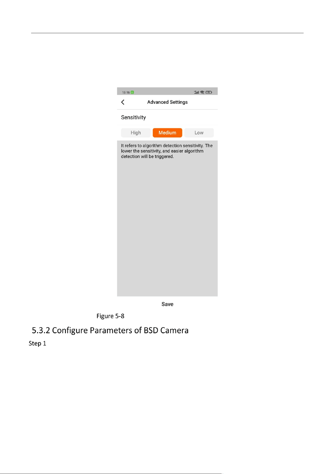
On the Advanced setting page, you can lower the alarm frequency by lowering its sensitivity.
Advanced Settings for Abnormal Detection
On the First Page, choose Channel 3 and tap Channel Configuration to enter the BSD setting
page.

Intelligent Driving Assistance Terminal • User Manual
23
BSD Settings
On the BSD setting page, tap BSD Setting to enter the setting page and configure
parameters.

Intelligent Driving Assistance Terminal • User Manual
24
BSD Settings
Tap Save to enable your configuration.
On BSD Parameter Settings page, you can
enable Right Side to warns against vehicles in the blind spot
choose the specific way to store the capture and recording
set the volume of the alarm
Tap Advanced Setting on BSD Parameter Settings page to enter advance setting.

Intelligent Driving Assistance Terminal • User Manual
25
Advanced Setting
On the Advanced setting page, you can
Configure the sensitivity of detection: the more sensitive it is, the easier that the algorithm
detection will be triggered.
Choose the algorithm detection type, calibrate the detection area.
Set the steering angle and link it.
Set the Calibration Detection Area
To calibrate the detection area:
Tap the Calibration Detection Area on the Advanced setting page.
Set the area by moving the 5 coordinate points.

Intelligent Driving Assistance Terminal • User Manual
26
Area Setting for BSD
Choose the level and view point of the area by tapping corresponding items.
Tap save to complete setting.
Intelligent Driving Assistance Terminal • User Manual
27
IPC Support
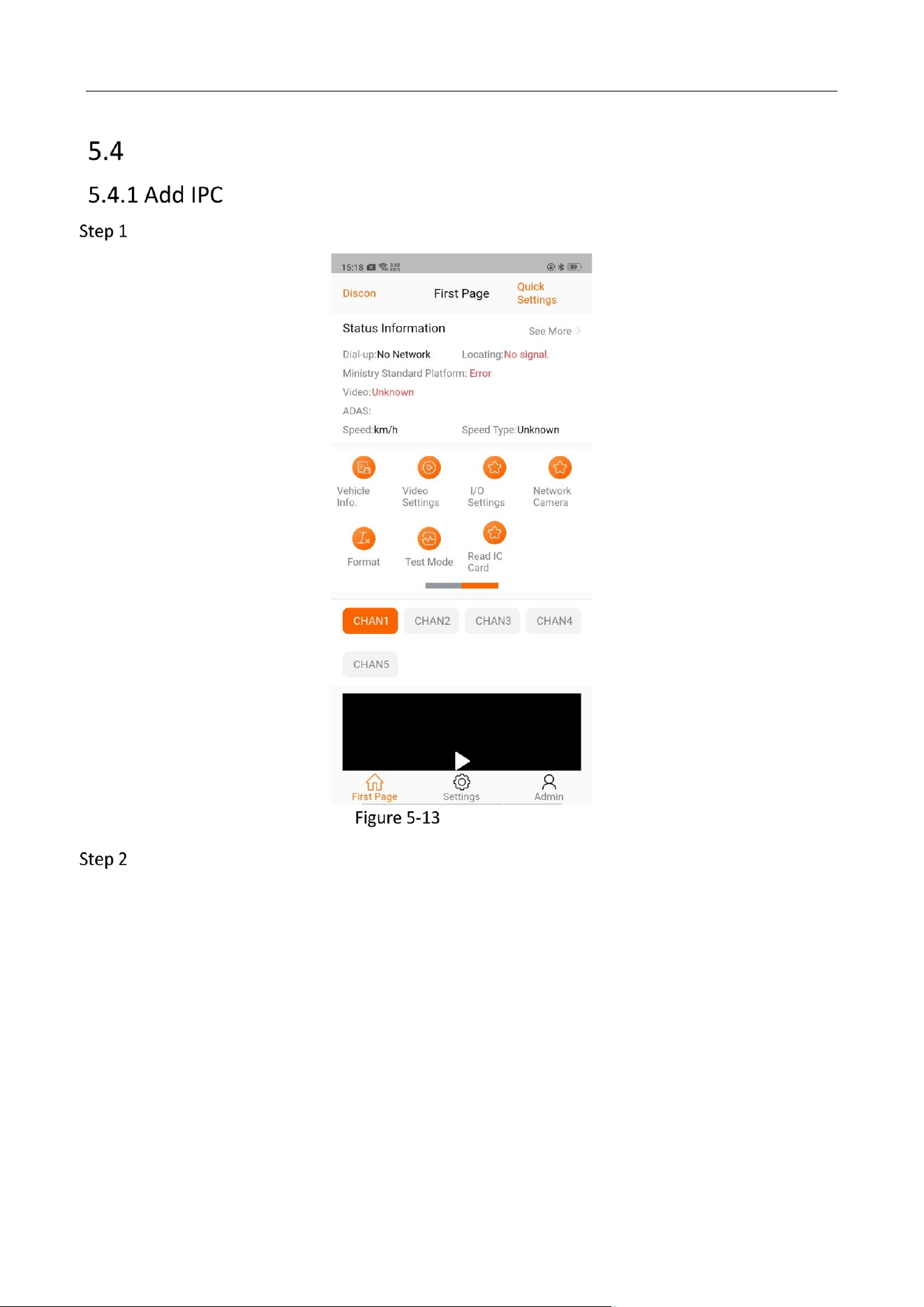
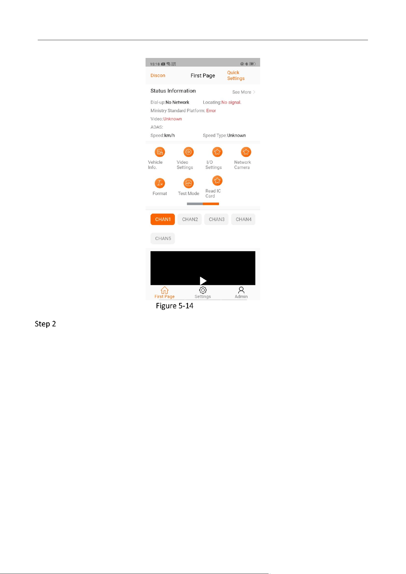
Tap Network Camera on the “First Page”.
Network Camera
Tap Device Can be Added and choose the IPC camera

Intelligent Driving Assistance Terminal • User Manual
28
Tap Quickly Add.
To check IPC added, tap Added Device.
To view video recorded, tap CHAN5 on the “First Page”.
At most 1 IPC can be added.
Tap Network Camera on the “First Page”.
Intelligent Driving Assistance Terminal • User Manual
29
Network Camera
Tap Added Device and select the device to be deleted.

Intelligent Driving Assistance Terminal • User Manual
30
Select the Device to be Deleted
Tap Delete.
Intelligent Driving Assistance Terminal • User Manual
31
Device Calibration
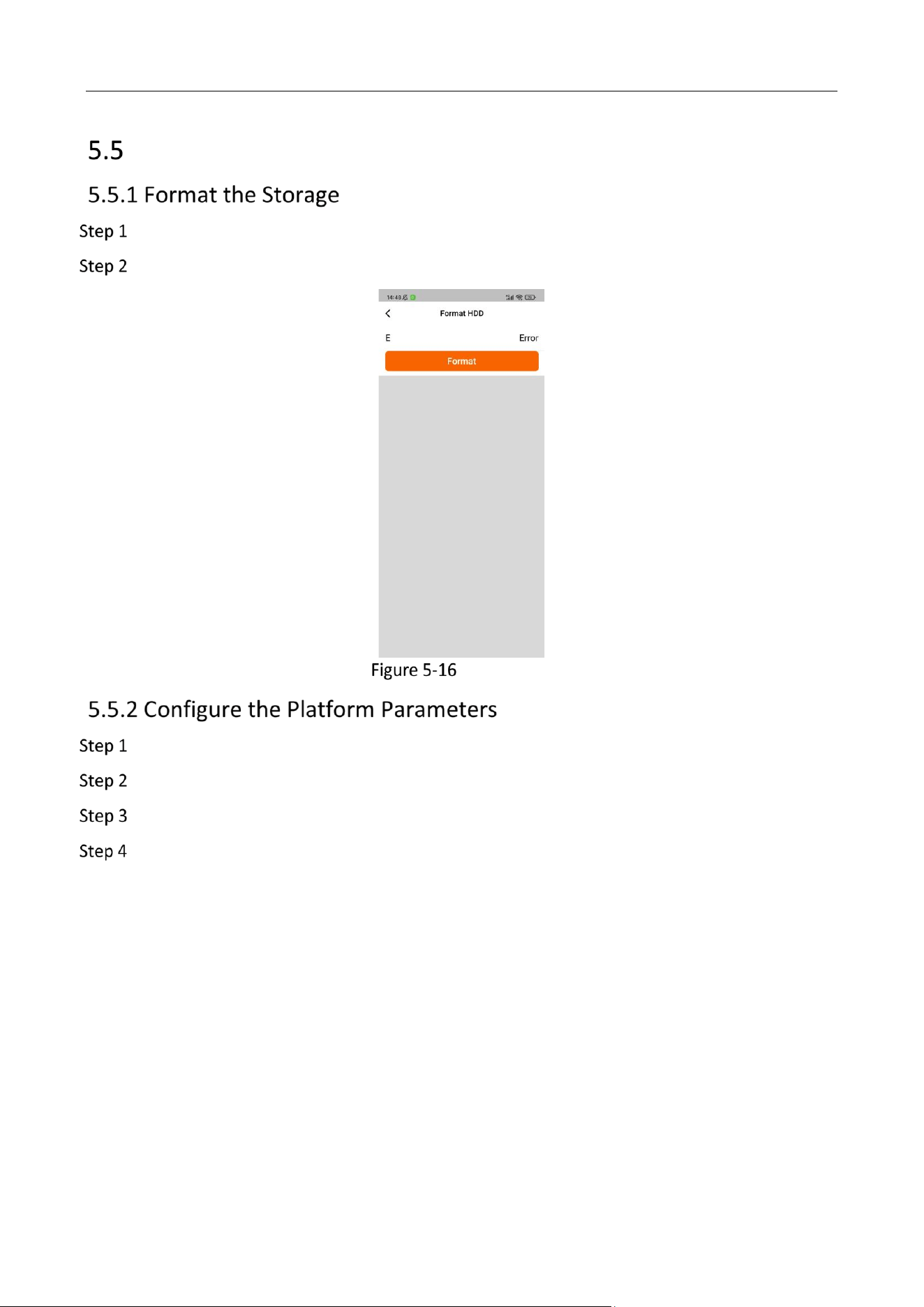
Tap Format on the “First Page”.
Choose the device to be formatted.
Format HDD
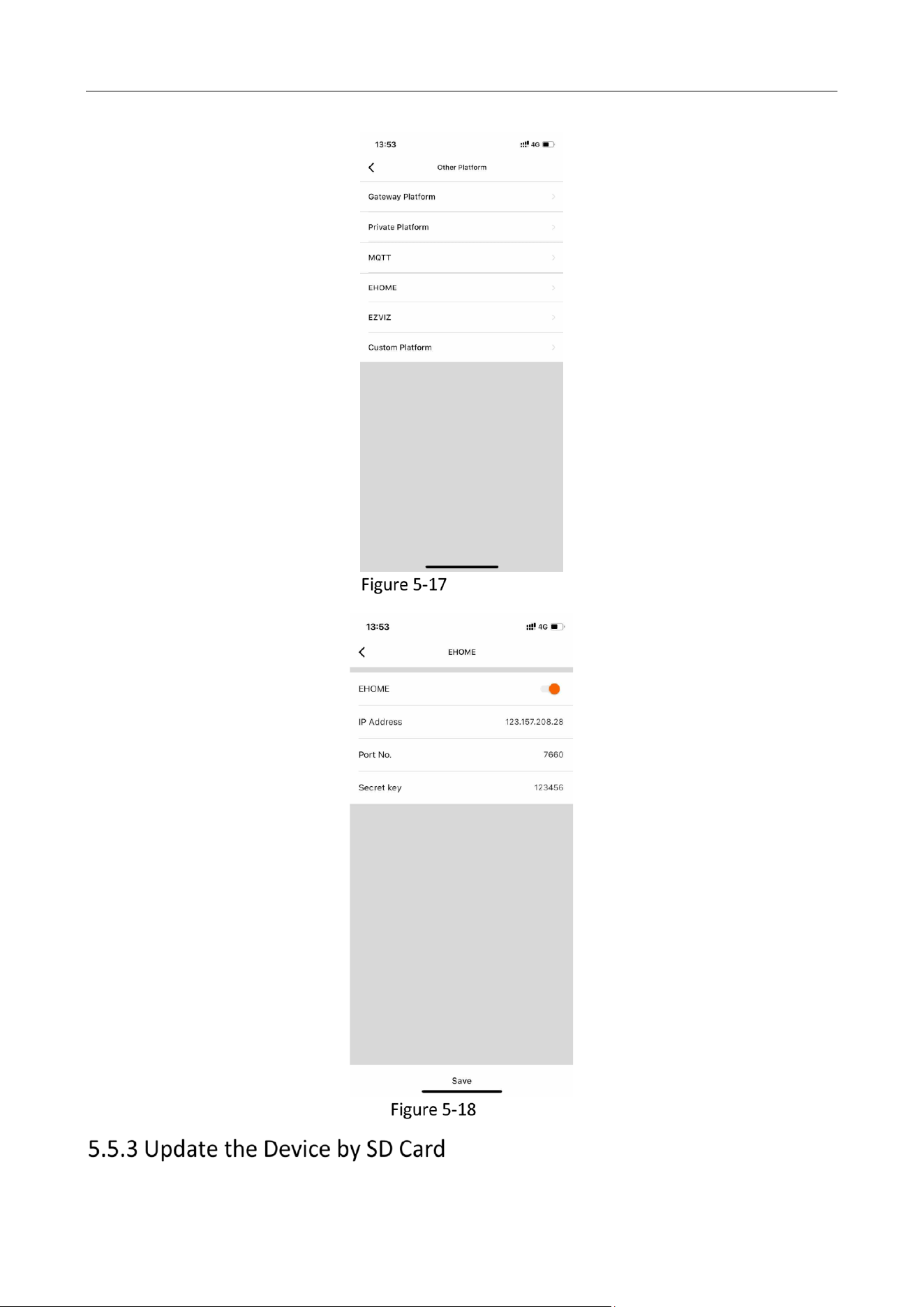
Tap Settings on the “First Page”.
Tap Other Platform.
Tap Ehome and enter HCP IP Address, Port No., and Secret key.
Configure parameters on HCP platform. To verify ISUP protocol, the device id needs to be
provided, which is identical to the serial number of the device.
Intelligent Driving Assistance Terminal • User Manual
32
Other Platform
Ehome
Intelligent Driving Assistance Terminal • User Manual
33
Before you start:
Format the SD Card in the device. For details, see 5.5.1 Format the Storage.
Copy the digicap.dav program to the root directory of the SD Card.
Insert the SD Card into the slot at the bottom of the device.
Connect the device to power supply and the update will start.
In the updating process, there will be voice prompt. The device will reboot after the update. The
digicap.dav program will be deleted. For testing and batch updating purpose, rename the update
program to “digicap_FACTORY_BACK_DOOR.dav” to keep it.
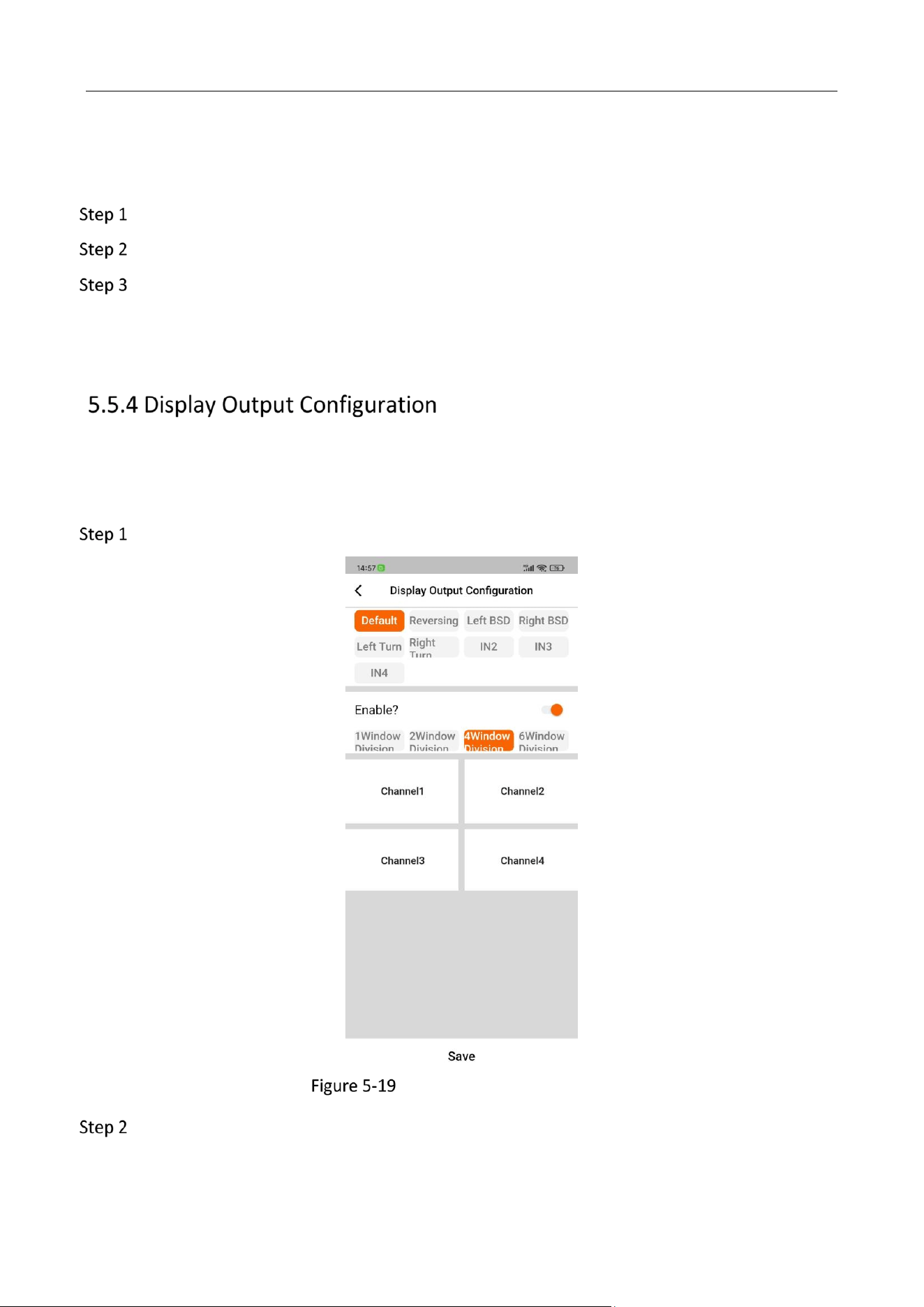
The display output can be configured to show the video of different cameras. 4 kinds of window
division are available: 1, 2, 4 and 6 window division.
To configure the output:
Choose the camera to be displayed.
Display Output Configuration
(optional) Enable the window division and choose the type of window division.
Tap Save to complete the setting.

0
