
1
Digital Video Recorder
Installation Guide

Digital Video Recorder Installation Guide
1
CONTENTS
Chapter 1 Panel Introduction ...................................................................................................... 6
Chapter 2 Installation and Connection ........................................................................................ 8
2.1 Environment ............................................................................................................................. 8
2.2 Install HDD .............................................................................................................................. 10
2.3 Install Positioning Antenna .................................................................................................... 13
2.4 Fix Device ............................................................................................................................... 14
Chapter 3 Device Wiring ........................................................................................................... 16
3.1 Power Cord Wiring ................................................................................................................. 16
3.2 Alarm Input Connection ......................................................................................................... 17
3.3 Alarm Output Connection ...................................................................................................... 18
3.4 Power on Device..................................................................................................................... 18

Digital Video Recorder Installation Guide
User Manual
COPYRIGHT © 2018 Hangzhou Hikvision Digital Technology Co., Ltd.
ALL RIGHTS RESERVED.
Any and all information, including, among others, wordings, pictures, graphs are the properties of
Hangzhou Hikvision Digital Technology Co., Ltd. or its subsidiaries (hereinafter referred to be
“Hikvision”). This user manual (hereinafter referred to be “the Manual”) cannot be reproduced,
changed, translated, or distributed, partially or wholly, by any means, without the prior written
permission of Hikvision. Unless otherwise stipulated, Hikvision does not make any warranties,
guarantees or representations, express or implied, regarding to the Manual.
About this Manual
This Manual is applicable to Digital Video Recorder.
The Manual includes instructions for using and managing the product. Pictures, charts, images and
all other information hereinafter are for description and explanation only. The information
contained in the Manual is subject to change, without notice, due to firmware updates or other
reasons. Please find the latest version in the company website
(http://overseas.hikvision.com/en/).
Please use this user manual under the guidance of professionals.
Trademarks Acknowledgement
and other Hikvision’s trademarks and logos are the properties of Hikvision in various
jurisdictions. Other trademarks and logos mentioned below are the properties of their respective
owners.
Legal Disclaimer
TO THE MAXIMUM EXTENT PERMITTED BY APPLICABLE LAW, THE PRODUCT DESCRIBED, WITH ITS
HARDWARE, SOFTWARE AND FIRMWARE, IS PROVIDED “AS IS”, WITH ALL FAULTS AND ERRORS,
AND HIKVISION MAKES NO WARRANTIES, EXPRESS OR IMPLIED, INCLUDING WITHOUT LIMITATION,
MERCHANTABILITY, SATISFACTORY QUALITY, FITNESS FOR A PARTICULAR PURPOSE, AND
NON-INFRINGEMENT OF THIRD PARTY. IN NO EVENT WILL HIKVISION, ITS DIRECTORS, OFFICERS,
EMPLOYEES, OR AGENTS BE LIABLE TO YOU FOR ANY SPECIAL, CONSEQUENTIAL, INCIDENTAL, OR
INDIRECT DAMAGES, INCLUDING, AMONG OTHERS, DAMAGES FOR LOSS OF BUSINESS PROFITS,
BUSINESS INTERRUPTION, OR LOSS OF DATA OR DOCUMENTATION, IN CONNECTION WITH THE
USE OF THIS PRODUCT, EVEN IF HIKVISION HAS BEEN ADVISED OF THE POSSIBILITY OF SUCH
DAMAGES.
REGARDING TO THE PRODUCT WITH INTERNET ACCESS, THE USE OF PRODUCT SHALL BE WHOLLY
AT YOUR OWN RISKS. HIKVISION SHALL NOT TAKE ANY RESPONSIBILITES FOR ABNORMAL
OPERATION, PRIVACY LEAKAGE OR OTHER DAMAGES RESULTING FROM CYBER ATTACK, HACKER
ATTACK, VIRUS INSPECTION, OR OTHER INTERNET SECURITY RISKS; HOWEVER, HIKVISION WILL
PROVIDE TIMELY TECHNICAL SUPPORT IF REQUIRED.
SURVEILLANCE LAWS VARY BY JURISDICTION. PLEASE CHECK ALL RELEVANT LAWS IN YOUR
JURISDICTION BEFORE USING THIS PRODUCT IN ORDER TO ENSURE THAT YOUR USE CONFORMS
THE APPLICABLE LAW. HIKVISION SHALL NOT BE LIABLE IN THE EVENT THAT THIS PRODUCT IS
USED WITH ILLEGITIMATE PURPOSES.
IN THE EVENT OF ANY CONFLICTS BETWEEN THIS MANUAL AND THE APPLICABLE LAW, THE LATER
PREVAILS.

Digital Video Recorder Installation Guide
Regulatory Information
FCC Information
Please take attention that changes or modification not expressly approved by the party
responsible for compliance could void the user’s authority to operate the equipment.
FCC compliance: This equipment has been tested and found to comply with the limits for a Class A
digital device, pursuant to part 15 of the FCC Rules. These limits are designed to provide
reasonable protection against harmful interference when the equipment is operated in a
commercial environment. This equipment generates, uses, and can radiate radio frequency energy
and, if not installed and used in accordance with the instruction manual, may cause harmful
interference to radio communications. Operation of this equipment in a residential area is likely to
cause harmful interference in which case the user will be required to correct the interference at
his own expense.
FCC Conditions
This device complies with Part 15 of the FCC Rules. Operation is subject to the following two
conditions:
(1) This device may not cause harmful interference, and
(2) This device must accept any interference received, including interference that may cause
undesired operation.
Attention that changes or modification not expressly approved by the party responsible for
compliance could void the user’s authority to operate the equipment.
Note: This product has been tested and found to comply with the limits for a Class B digital device,
pursuant to Part 15 of the FCC Rules. These limits are designed to provide reasonable protection
against harmful interference in a residential installation. This product generates, uses, and can
radiate radio frequency energy and, if not installed and used in accordance with the instructions,
may cause harmful interference to radio communications. However, there is no guarantee that
interference will not occur in a particular installation. If this product does cause harmful
interference to radio or television reception, which can be determined by turning the equipment
off and on, the user is encouraged to try to correct the interference by one or more of the
following measures:
—Reorient or relocate the receiving antenna.
—Increase the separation between the equipment and receiver.
—Connect the equipment into an outlet on a circuit different from that to which the receiver is
connected.
—Consult the dealer or an experienced radio/TV technician for help.
This equipment should be installed and operated with a minimum distance 20cm between the
Digital Video Recorder Installation Guide
radiator and your body
EU Conformity Statement
This product and - if applicable - the supplied accessories too are marked with "CE" and
comply therefore with the applicable harmonized European standards listed under the
EMC Directive 2014/30/EU, the LVD Directive 2014/35/EU, the RoHS Directive 2011/65/EU.
2012/19/EU (WEEE directive): Products marked with this symbol cannot be disposed of
as unsorted municipal waste in the European Union. For proper recycling, return this
product to your local supplier upon the purchase of equivalent new equipment, or
dispose of it at designated collection points. For more information see: www.recyclethis.info
2006/66/EC (battery directive): This product contains a battery that cannot be disposed
of as unsorted municipal waste in the European Union. See the product documentation
for specific battery information. The battery is marked with this symbol, which may
include lettering to indicate cadmium (Cd), lead (Pb), or mercury (Hg). For proper recycling, return
the battery to your supplier or to a designated collection point. For more information see:
www.recyclethis.info
Industry Canada ICES-003 Compliance
This device meets the CAN ICES-3 (A)/NMB-3(A) standards requirements.
Symbol Conventions
The symbols that may be found in this document are defined as follows.
Symbol
Description
Provides additional information to emphasize or supplement
important points of the main text.
Indicates a potentially hazardous situation, which if not avoided,
could result in equipment damage, data loss, performance
degradation, or unexpected results.
Indicates a hazard with a high level of risk, which if not avoided, will
result in death or serious injury.

Digital Video Recorder Installation Guide
Safety Instructions
Proper configuration of all passwords and other security settings is the responsibility of the
installer and/or end-user.
In the use of the product, you must be in strict compliance with the electrical safety
regulations of the nation and region. Please refer to technical specifications for detailed
information.
Input voltage should meet both the SELV (Safety Extra Low Voltage) and the Limited Power
Source with 9 to 32 VDC according to the IEC60950-1 standard. Please refer to technical
specifications for detailed information.
Do not connect several devices to one power adapter as adapter overload may cause
over-heating or a fire hazard.
Please make sure that the plug is firmly connected to the power socket.
If smoke, odor or noise rise from the device, turn off the power at once and unplug the power
cable, and then please contact the service center.
Preventive and Cautionary Tips
Before connecting and operating your device, please be advised of the following tips:
Ensure unit is installed in a well-ventilated, dust-free environment.
Keep all liquids away from the device.
Ensure environmental conditions meet factory specifications.
Ensure unit is properly secured to a rack or shelf. Major shocks or jolts to the unit as a result of
dropping it may cause damage to the sensitive electronics within the unit.
Use the device in conjunction with an UPS if possible.
Power down the unit before connecting and disconnecting accessories and peripherals.
A factory recommended HDD should be used for this device.
Improper use or replacement of the battery may result in hazard of explosion. Replace with
the same or equivalent type only. Dispose of used batteries according to the instructions
provided by the battery manufacturer.
Ensure the device is well grounded.
Digital Video Recorder Installation Guide
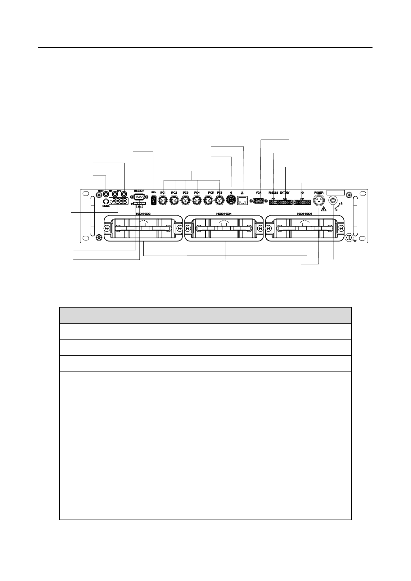
Chapter 1 Panel Introduction
Refer to the following figure and table for the panel description.
14
2
3
4
1
5
6
9
8
16
10
15
13
11
12
7
17
Figure 1-1 Front Panel
Table 1-1 Interface Description
No.
Name
Description
1
Wi-Fi antenna interfaces
Reserved.
2
M-ANT
Reserved.
3
GNSS
GNSS antenna interface.
4
PWR
Power indicator:
Solid green: Device is powered on.
Solid red: Device is standby.
IPC
Camera indicator:
Flashing green: Camera is connected and data
are transmitted.
Unlit: Camera is offline. Check power supply and
wiring.
REC
Recording indicator
Solid green: Device is recording normally.
G
Network interface indicator (G):

Digital Video Recorder Installation Guide
Flashing green: Network transmission is normal.
Unlit: No network. Check network cable
connection and IP address.
HDD
HDD indicator (HDD):
Solid green: HDD is working normally.
Unlit: No HDD. Check HDD installation.
ALM
Alarm indicator
Red: Alarm occurs.
5
SIM card slot
Reserved.
6
RS-232-1
For debugging.
7
USB interface
USB 3.0 interface.
8
IPC1 to IPC6
6 video inputs. Connects to cameras.
9
100M network interface
RJ45 10M/100M Ethernet interface.
10
1000M network
interface
Connects to switch and network camera.
11
Dummy HDD
For HDD installation.
12
VGA
VGA video output interface.
13
RS-232-2
Connects to external devices.
14
EXT.DEV
RS-422 communication interface, two-way audio
interface, and CVBS video output.
15
I/O
ALARM IN: Connects to vehicle high/low level
signal as alarm signal source.
ALARM OUT: ALARM OUT n and ALARM OUT n#
are one pair of alarm output interfaces to
control peripheral devices.
16
Power
3-pin aviation plug for power supply.
17
Dummy HDD lock
Lock/Unlock the dummy HDD.
Digital Video Recorder Installation Guide
Chapter 2 Installation and Connection
Device pictures in following sections are only for reference. In condition that product pictures
conflict the real device, the later prevails.
Before you start:
Take out the device from the package. Check the device and accessories status. Please contact us if
something is missing or damaged.
2.1 Environment
Consider the following environment conditions when installing the device.
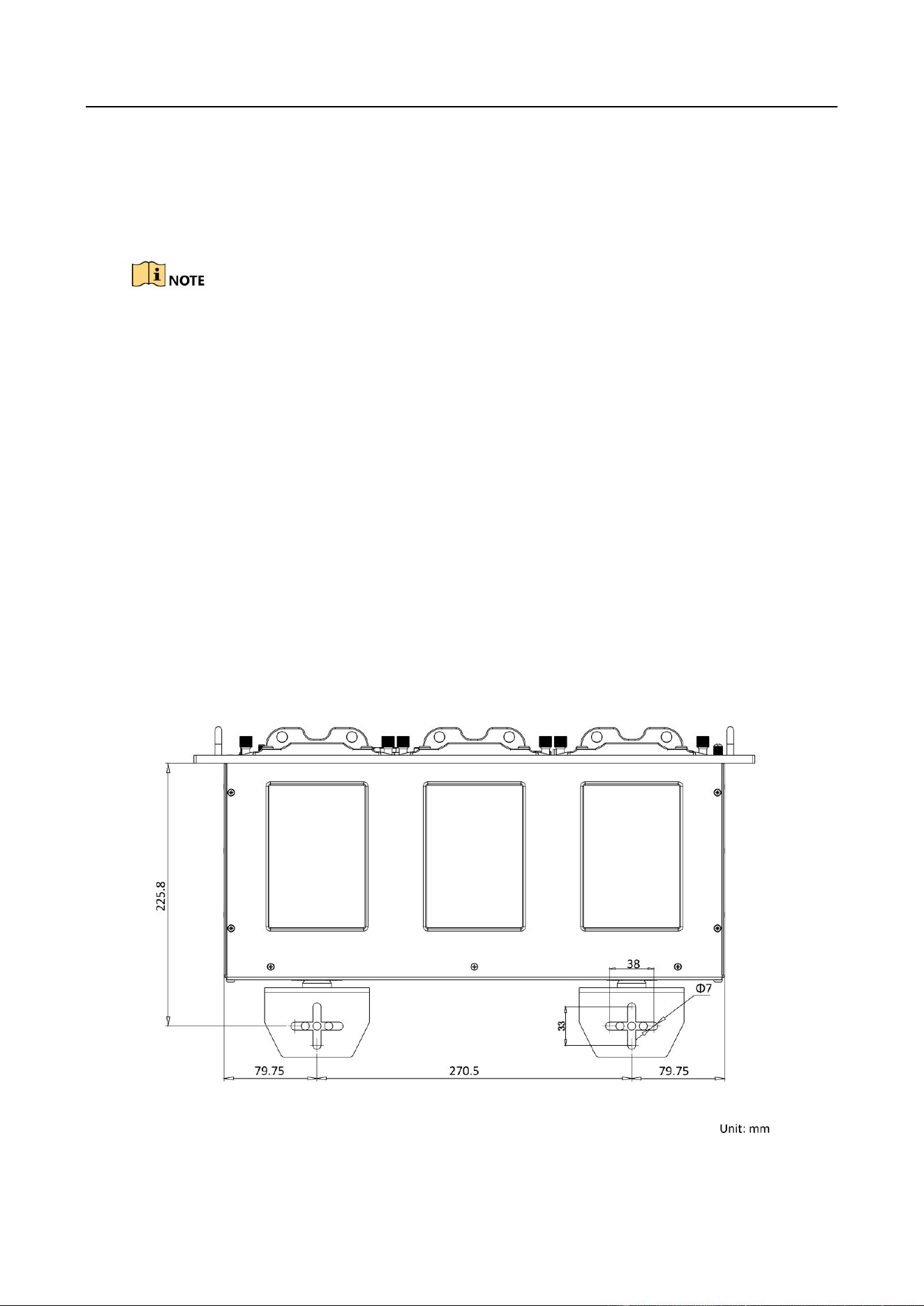
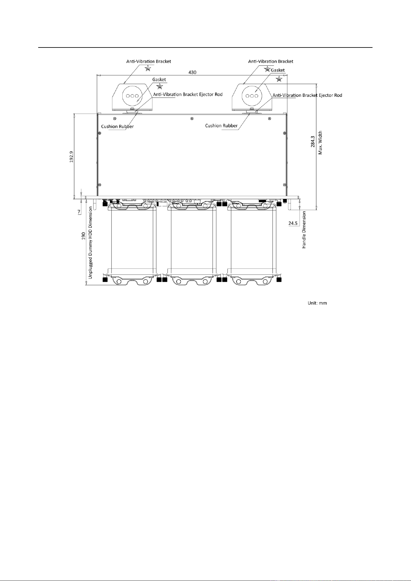
Anti-vibration
Normal vehicle: Install the device on the part with weak vibration (such as the part behind the
driver seat, the part behind the passenger seat, etc.) and far away from the engine.
Rail traffic: It is recommended to install the device in the electric cabinet.
Anti-vibration bracket is needed for the device installation. The dimension of the bracket
installation hole is shown as below.
Figure 2-1 Anti-Vibration Bracket Installation Hole Dimension
Digital Video Recorder Installation Guide
Heat dissipation
Install the device in the position far away from heat and ventilates well for good heat
dissipation.
Enough space
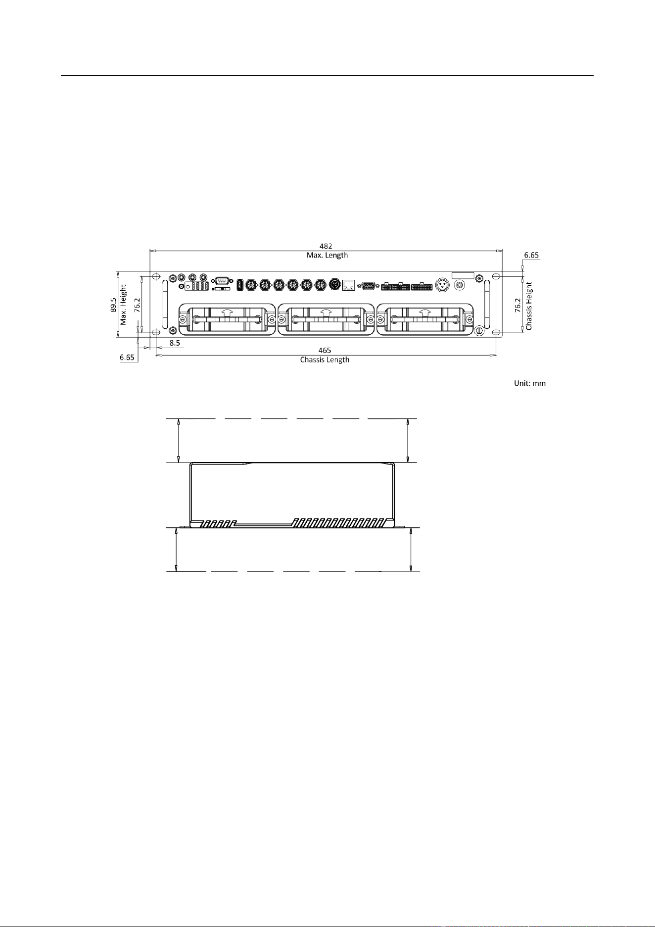
Leave enough space for the device chassis as shown in Figure 2-2. Leave enough space for
ventilation, heat dissipation, plugging or unplugging dummy HDD, etc. as shown in Figure 2-3
and Figure 2-4.
Figure 2-2 Device Chassis Installation Dimension
40
Unit:mm
40
Device Space
40
40
Figure 2-3 Recommended Installation Space (1)
Digital Video Recorder Installation Guide
Figure 2-4 Recommended Installation Space (2)
Placing angle
Place the device horizontally. The other placing angles may damage the device.
Fixing position
All the screws in the fixing positions must be fastened tightly to avoid device falling during the
vibration in driving.
2.2 Install HDD
The device leaves factory with HDD. If you need to change HDD, follow the steps below to install
HDD.
Before You Start:
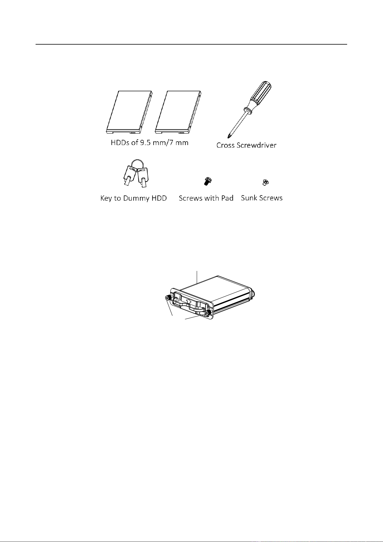
Prepare the tools and components for installation:
Factory recommended 2.5-inch HDD.
Antistatic gloves.
Key to dummy HDD (delivered with device).
Digital Video Recorder Installation Guide
Cross screwdriver.
Screws (delivered with device).
Figure 2-5 Tools
Step 1 Wear antistatic gloves.
Step 2 Insert the key and turn counterclockwise to unlock dummy HDD.
Step 3 Unfasten the two screws of dummy HDD and pull dummy HDD out of device.
Unfasten Screws
Dummy HDD
Figure 2-6 Pull Dummy HDD out
Step 4 Use cross screwdriver to loosen the two screws and remove them, and then take the dummy
HDD apart.
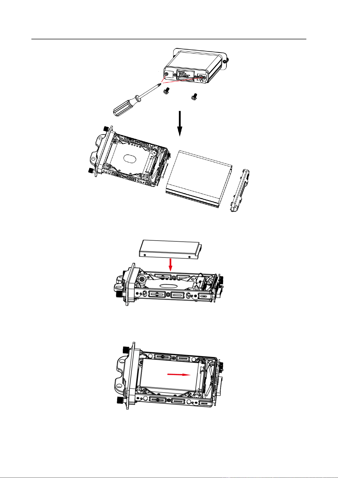
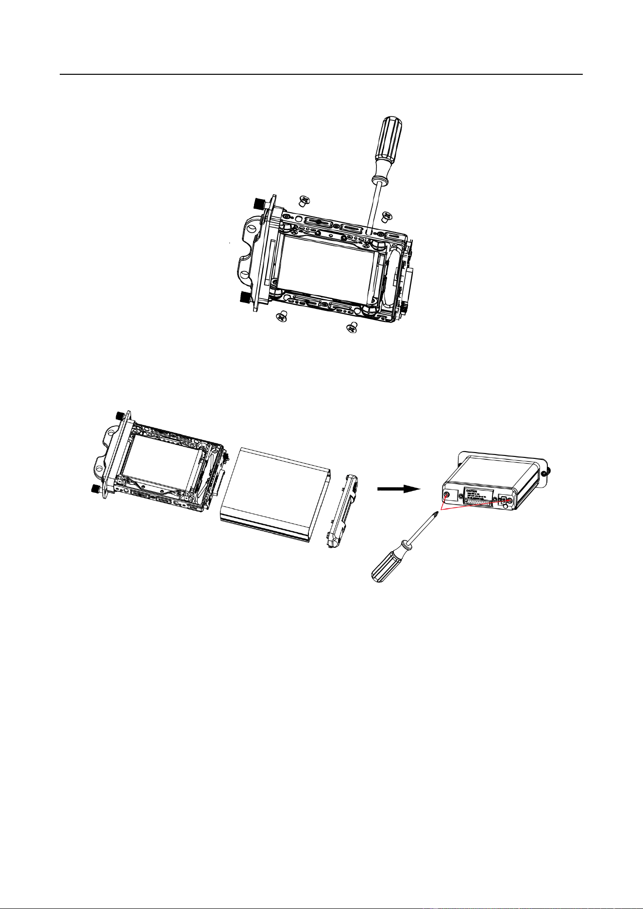
Digital Video Recorder Installation Guide
Step 7 Use four sunk screws to fix HDD with dummy HDD.
Figure 2-10 Fix HDD
Step 8 Repeat step 4 to 7 to install more HDDs.
Step 9 Reassemble the dummy HDD.
Figure 2-11 Reassemble Dummy HDD
Step 10 Plug the dummy HDD back to the device and then tighten the screws clockwise.
Step 11 Turn the key clockwise to lock dummy HDD.
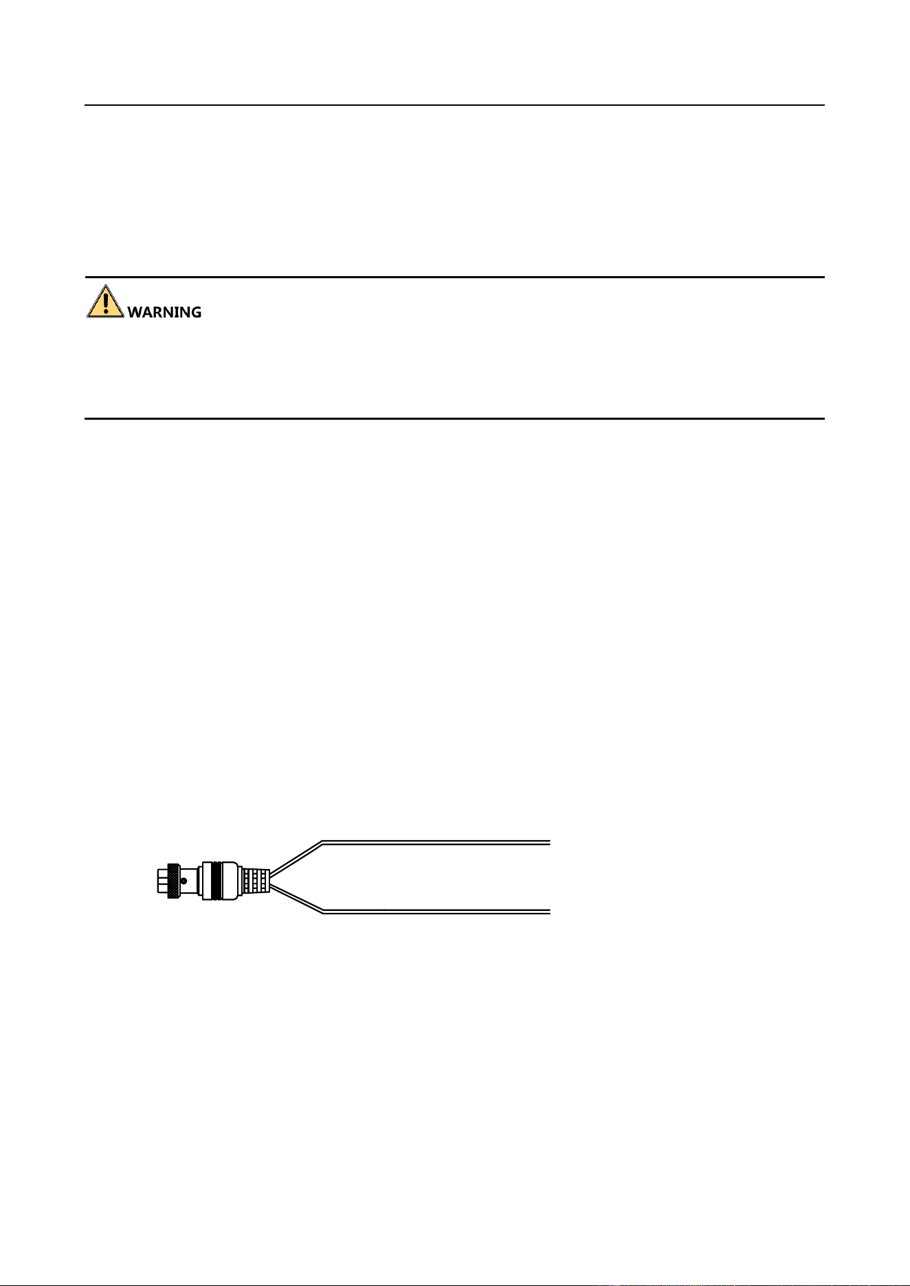
2.3 Install Positioning Antenna
Connect positioning antenna to GNSS interface.
Place antenna vertically with its signal receiving end facing upward.
If the cable is too long, you can roll them up to prevent signal receiving from being affected.
Vertically install positioning antenna on the automobile roof with no shelter.

Digital Video Recorder Installation Guide
Figure 2-12 Install Positioning Antenna on Automobile Roof
Follow the instructions below in case that you need to install positioning antenna inside your
automobile.
Install antenna on platform under the front windshield.
Windshield
Antenna
Figure 2-13 Install Positioning Antenna Inside Automobile
Fix antenna with neutral silica gel.
When adjusting the antenna position, ensure that at least 4 satellites have a signal
strength above 35 dB. You can go to Configuration > Vehicle > Position Settings >
Location Status to view positioning signal status.
2.4 Fix Device
Purpose
The device is recommended to fix in the cabinet.
Before you start
Prepare the cabinet which is designed according to the device dimensions and reserved space.
Step 1 Punch holes on the appropriate positions of the cabinet according to the positions of bracket
holes in the package.
Step 2 Align the holes on the bracket with those on the device panel, and tighten screws to fix the
bracket on the device panel.
Step 3 Push the device into the cabinet slowly to align the holes on the bracket with those on the
cabinet.
Step 4 Tighten screws to fix the device on the cabinet.
Result

Digital Video Recorder Installation Guide
Figure 2-14 Fix Device
Digital Video Recorder Installation Guide
Chapter 3 Device Wiring
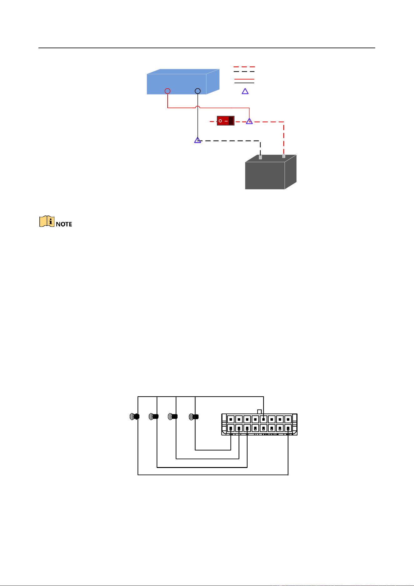
3.1 Power Cord Wiring
In order to ensure the safety of your automobile and device, a fuse is required for wiring of
automobile power and device power.
Do not connect the power cord to the device before all the cables are connected.
Purpose
The device starts up when your automobile ignites and shuts down after automobile is off.
Automobile ignition startup and shutdown are realized by automobile positive pole ignition switch
(providing high level signal when the switch closes). The wire connection of the device varies with
the automobile ignition models.
Ignition switch is connected to the positive pole of automobile batteries. Make sure that the
connection is correct, and then perform the following steps:
Step 1 Connect the "DC IN +" of the device to the positive pole of automobile batteries, jumping
over the switch of normal automobile power.
Step 2 Connect the "DC IN -" of the device to the negative pole of automobile batteries.
Step 3 Place the fuse into the fuse holder.
What to do next: For detailed time settings of time-delay shutdown, see Chapter Configure
Delayed Shutdown in user manual.
DC+
DC-
Connect to positive pole of
automobile batteries.
Connect to negative pole of
automobile batteries.
Figure 3-1 Power Cord
Digital Video Recorder Installation Guide
DC IN
+
-
Device
Automobile
Battery
Automobile Power System
Wiring of Device
Point of Connection
Positive Pole
Negative Pole
DC IN
Automobile Power Switch
Figure 3-2 Wiring
Please contact the automobile manufacturer for the connection information of starting
switch.
The automobile ignition switch, also called car key, controls the startup and shutdown of
your automobile. Most of automobiles adopt positive pole ignition switch currently.
The normal automobile power refers to the main power of the automobile power supply
system. After the automobile is off, the normal automobile power still provides
direct-current source for the other devices inside and generally a main switch is used to
turn on/off it.
3.2 Alarm Input Connection
The device adopts the high/low-level electrical signals triggering (high level: 6 to 36 VDC; low level:
0 to 5 VDC) to realize alarm input. And in order to avoid error report caused by voltage fluctuation,
no alarm will be triggered by voltage ranging of 5 to 6 VDC.
Alarm 1
IO
Alarm 2
Alarm 3
Alarm 4
1
2
15
16
Figure 3-3 Alarm Input Connection
Digital Video Recorder Installation Guide
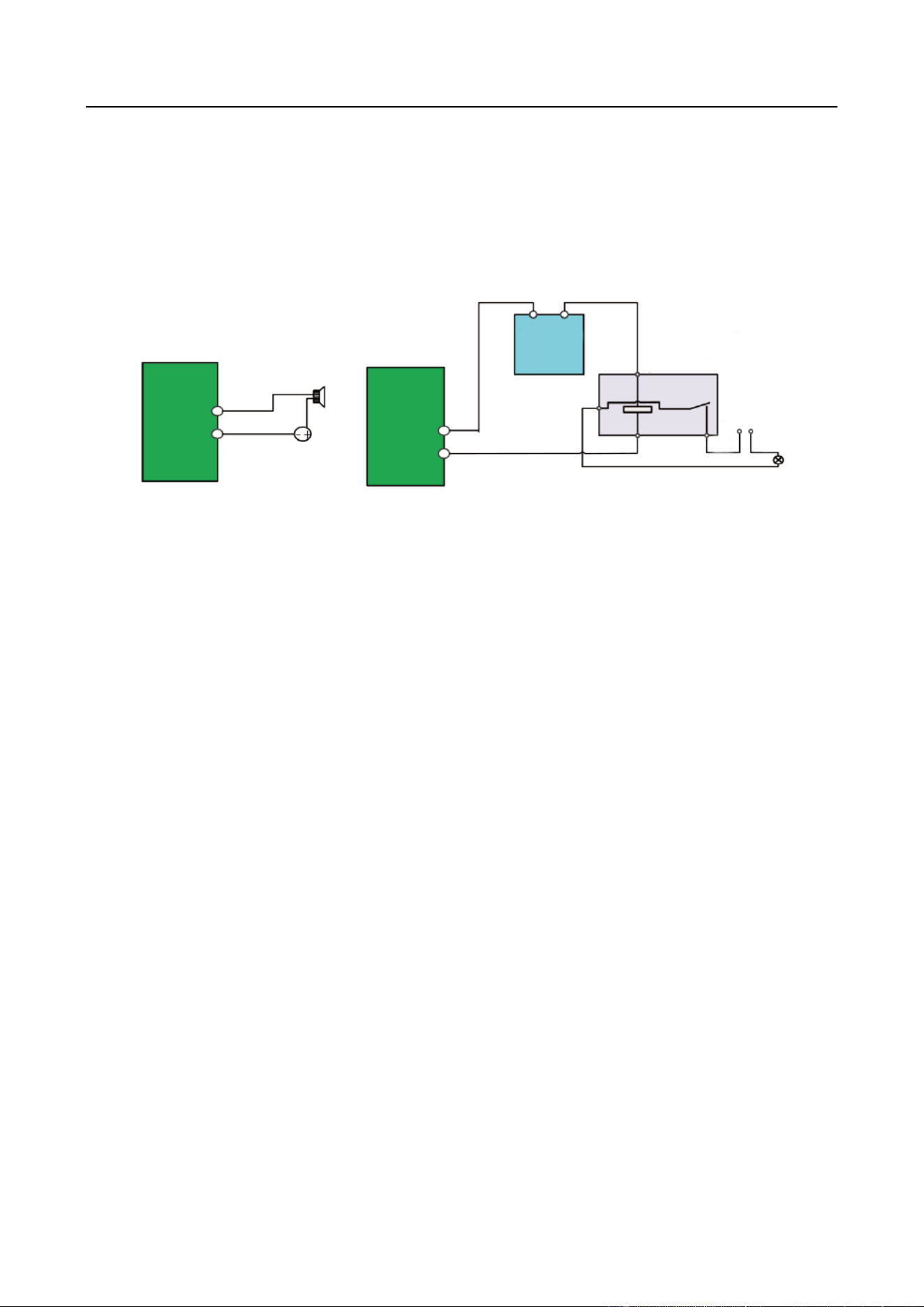
3.3 Alarm Output Connection
Follow the figure bellow to wire alarm output.
n and n# are a pair of alarm output. You can connect them with a relay alarm device. When the
voltage of connected alarm device exceeds the valid alarm output range, you need to connect a
relay to protect alarm output.
Relay
Output
n
n#
Load
GND
Power
Output
JQC-3FG
Relay
(10 A/250 VAC)
~ 220 VAC
NeutralLive
Relay
Output
n#
n
Alarm Powered by Direct Current Alarm Powered by Alternating Current
Figure 3-4 Alarm Output Connection
3.4 Power on Device
Turn on the power supply after all the above installation and connection are finished.
You can view the indicators to get knowledge about the device status. For details, refer to Table
1-1.

Digital Video Recorder Installation Guide
0
UD11776B