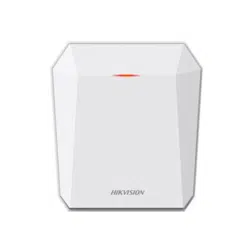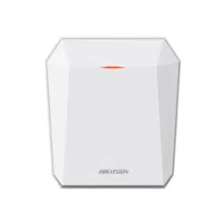

Auxiliary Care Radar
User Manual

Legal Informaon
©2023 Hangzhou Hikvision Digital Technology Co., Ltd. All rights reserved.
About this Manual
The Manual includes instrucons for using and managing the Product. Pictures, charts, images and
all other informaon hereinaer are for descripon and explanaon only. The informaon
contained in the Manual is subject to change, without noce, due to rmware updates or other
reasons. Please nd the latest version of this Manual at the Hikvision website ( hps://
www.hikvision.com/ ).
Please use this Manual with the guidance and assistance of professionals trained in
supporng the
Product.
Trademarks
and other Hikvision's trademarks and logos are the properes of
Hikvision in various jurisdicons.
Other trademarks and logos menoned are the properes of their respecve owners.
Disclaimer
TO THE MAXIMUM EXTENT PERMITTED BY APPLICABLE LAW, THIS MANUAL AND THE PRODUCT
DESCRIBED, WITH ITS HARDWARE, SOFTWARE AND FIRMWARE, ARE PROVIDED "AS IS" AND "WITH
ALL FAULTS AND ERRORS". HIKVISION MAKES NO WARRANTIES, EXPRESS OR IMPLIED, INCLUDING
WITHOUT LIMITATION, MERCHANTABILITY, SATISFACTORY QUALITY, OR FITNESS FOR A PARTICULAR
PURPOSE. THE USE OF THE PRODUCT BY YOU IS AT YOUR OWN RISK. IN NO EVENT WILL HIKVISION
BE LIABLE TO YOU FOR ANY SPECIAL, CONSEQUENTIAL, INCIDENTAL, OR INDIRECT DAMAGES,
INCLUDING, AMONG OTHERS, DAMAGES FOR LOSS OF BUSINESS PROFITS, BUSINESS
INTERRUPTION, OR LOSS OF DATA, CORRUPTION OF SYSTEMS, OR LOSS OF DOCUMENTATION,
WHETHER BASED ON BREACH OF CONTRACT, TORT (INCLUDING NEGLIGENCE), PRODUCT LIABILITY,
OR OTHERWISE, IN CONNECTION WITH THE USE OF THE PRODUCT, EVEN IF HIKVISION HAS BEEN
ADVISED OF THE POSSIBILITY OF SUCH DAMAGES OR LOSS.
YOU ACKNOWLEDGE THAT THE NATURE OF THE INTERNET PROVIDES FOR INHERENT SECURITY
RISKS, AND HIKVISION SHALL NOT TAKE ANY RESPONSIBILITIES FOR ABNORMAL OPERATION,
PRIVACY LEAKAGE OR OTHER DAMAGES RESULTING FROM CYBER-ATTACK, HACKER ATTACK, VIRUS
INFECTION, OR OTHER INTERNET SECURITY RISKS; HOWEVER, HIKVISION WILL PROVIDE TIMELY
TECHNICAL SUPPORT IF REQUIRED.
YOU AGREE TO USE THIS PRODUCT IN COMPLIANCE WITH ALL APPLICABLE LAWS, AND YOU ARE
SOLELY RESPONSIBLE FOR ENSURING THAT YOUR USE CONFORMS TO THE APPLICABLE LAW.
ESPECIALLY, YOU ARE RESPONSIBLE, FOR USING THIS PRODUCT IN A MANNER THAT DOES NOT
INFRINGE ON THE RIGHTS OF THIRD PARTIES, INCLUDING WITHOUT LIMITATION, RIGHTS OF
PUBLICITY, INTELLECTUAL PROPERTY RIGHTS, OR DATA PROTECTION AND OTHER PRIVACY RIGHTS.
YOU SHALL NOT USE THIS PRODUCT FOR ANY PROHIBITED END-USES, INCLUDING THE
Auxiliary Care Radar User Manual
i

DEVELOPMENT OR PRODUCTION OF WEAPONS OF MASS DESTRUCTION, THE DEVELOPMENT OR
PRODUCTION OF CHEMICAL OR BIOLOGICAL WEAPONS, ANY ACTIVITIES IN THE CONTEXT RELATED
TO ANY NUCLEAR EXPLOSIVE OR UNSAFE NUCLEAR FUEL-CYCLE, OR IN SUPPORT OF HUMAN
RIGHTS ABUSES.
IN THE EVENT OF ANY CONFLICTS BETWEEN THIS MANUAL AND THE APPLICABLE LAW, THE LATTER
PREVAILS.
Auxiliary Care Radar User Manual
ii
Symbol Convenons
The symbols that may be found in this document are dened as follows.
Symbol Descripon
Danger
Indicates a hazardous situaon which, if not avoided, will or could
result in death or serious injury.
Cauon
Indicates a potenally hazardous situaon which, if not avoided, could
result in equipment damage, data loss, performance degradaon, or
unexpected results.
Note
Provides addional informaon to emphasize or supplement
important points of the main text.
Auxiliary Care Radar User Manual
iii

Contents
Chapter 1 Introducon ............................................................................................................... 1
1.1 Product Introducon .............................................................................................................. 1
1.2 Key Feature ............................................................................................................................ 1
Chapter 2 Acvaon and Login ................................................................................................... 2
2.1 Acvaon ............................................................................................................................... 2
2.1.1 Default Informaon ...................................................................................................... 2
2.1.2 Acvate via SADP .......................................................................................................... 2
2.1.3 Acvate via Web Browser ............................................................................................. 3
2.2 Login ...................................................................................................................................... 4
Chapter 3 Radar
Detecon ......................................................................................................... 5
3.1 Set Radar Mode ..................................................................................................................... 5
3.2 Set
Detecon Parameters ...................................................................................................... 6
Chapter 4 Storage ....................................................................................................................... 8
4.1 Set SDK Listening .................................................................................................................... 8
4.2 Set ISAPI Listening .................................................................................................................. 8
Chapter 5 Network
Conguraon ............................................................................................... 9
5.1 Set IP Address ........................................................................................................................ 9
5.2 Set Wi-Fi ............................................................................................................................... 11
5.3 Set Wi-Fi AP ......................................................................................................................... 11
5.4 Connect to
Plaorm ............................................................................................................. 12
5.4.1 Connect to OTAP ......................................................................................................... 12
5.4.2 Connect to Hik-Connect .............................................................................................. 13
5.5 Set DDNS .............................................................................................................................. 13
5.6 Set SNMP ............................................................................................................................. 14
5.7 Set IEEE 802.1X .................................................................................................................... 15
5.8 Set Port ................................................................................................................................ 15
Auxiliary Care Radar User Manual
iv

Chapter 6 Excepon Alarm ....................................................................................................... 17
Chapter 7 Safety Management ................................................................................................. 18
7.1 Manage User ........................................................................................................................ 18
7.2 Enable User Lock .................................................................................................................. 18
7.3 Install Authorized
Cercate ................................................................................................ 19
7.4 Create and Install Self-signed Cercate ............................................................................. 19
7.5 Set SSH ................................................................................................................................. 19
7.6 Set IP Address Filtering ........................................................................................................ 20
7.7 Set Timeout Logout .............................................................................................................. 20
7.8 Set Password Validity Period ................................................................................................ 20
Chapter 8 Maintenance ............................................................................................................ 22
8.1 View Device Informaon ...................................................................................................... 22
8.2 Log ....................................................................................................................................... 22
8.2.1 Enable System Log Service .......................................................................................... 22
8.2.2 Enable Log According to Module ................................................................................ 22
8.3 Upgrade ............................................................................................................................... 23
8.4 Reboot ................................................................................................................................. 23
8.5 Restore Parameters .............................................................................................................. 23
8.6 Set Serial Port ....................................................................................................................... 24
8.7 Synchronize Time ................................................................................................................. 24
8.8 Set DST ................................................................................................................................. 25
8.9 Export Parameters ............................................................................................................... 25
8.10 Import
Conguraon File ................................................................................................... 26
8.11 Export Debug File ............................................................................................................... 26
8.12 Export Diagnosis Informaon ............................................................................................ 27
Appendix A.
Communicaon Matrix and Device Command ...................................................... 28
Auxiliary Care Radar User Manual
v

Chapter 1 Introducon
1.1 Product Introducon
Auxiliary care radar (hereinaer referred to as “device”) adopts FMCW, MIMO, beamforming,
micro-Doppler feature extracon, and other technologies. It can detect the vital signs, including
human body, breath, heartbeat, etc.
The device can be installed above the bed in the bedroom, and the non-contact detecon will
cover the bed. It can obtain the
informaon, including the me in the bed, the me out of the bed,
breath rate, heart rate, mes of movements, etc., and help to analyze the sleep quality and health
of the human body.
1.2 Key Feature
●
Real-me and non-contact detecon. No privacy disclosure.
●
Supports to connect to OTAP.
●
Supports data transmission via Wi-Fi.
●
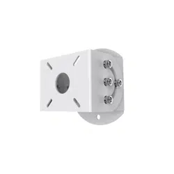
Small size and easy installaon.
●
It can be used to the indoor safety and health monitoring for the elderly people in hospitals,
nursing homes, and other scenarios.
Auxiliary Care Radar User Manual
1

Chapter 2 Acvaon and Login
2.1 Acvaon
For the rst-me access, you need to acvate the device by seng an admin password. No
operaon is allowed before acvaon. The device supports mulple acvaon methods, such as
acvaon via SADP soware, web browser, and iVMS-4200 Client.
Note
Refer to the user manual of iVMS-4200 Client for the acvaon via client soware.
2.1.1 Default Informaon
The device default informaon is shown as below.
●
Default IP address: 192.168.1.64
●
Default user name: admin
2.1.2
Acvate via SADP
SADP is a tool to detect, acvate, and modify the IP address of the device over the LAN.
Before You Start
●
Get the SADP soware from the supplied disk or the ocial website ( hp://
www.hikvision.com/ ), and install it according to the prompts.
●
The device and the computer that runs the SADP tool should belong to the same network
segment.
The following steps show how to
acvate one device and modify its IP address. For batch acvaon
and IP address modicaon, refer to User Manual of SADP for details.
Steps
1.
Run the SADP soware and search the online devices.
2.
Find and select your device in online device list.
3.
Enter a new password (admin password) and
conrm the password.
Cauon
STRONG PASSWORD RECOMMENDED-We highly recommend you create a strong password of
your own choosing (using a minimum of 8 characters, including upper case leers, lower case
leers, numbers, and special characters) in order to increase the security of your product. And
we recommend you reset your password regularly, especially in the high security system,
reseng the password monthly or weekly can beer protect your product.
4.
Click Acvate to start acvaon.
Auxiliary Care Radar User Manual
2
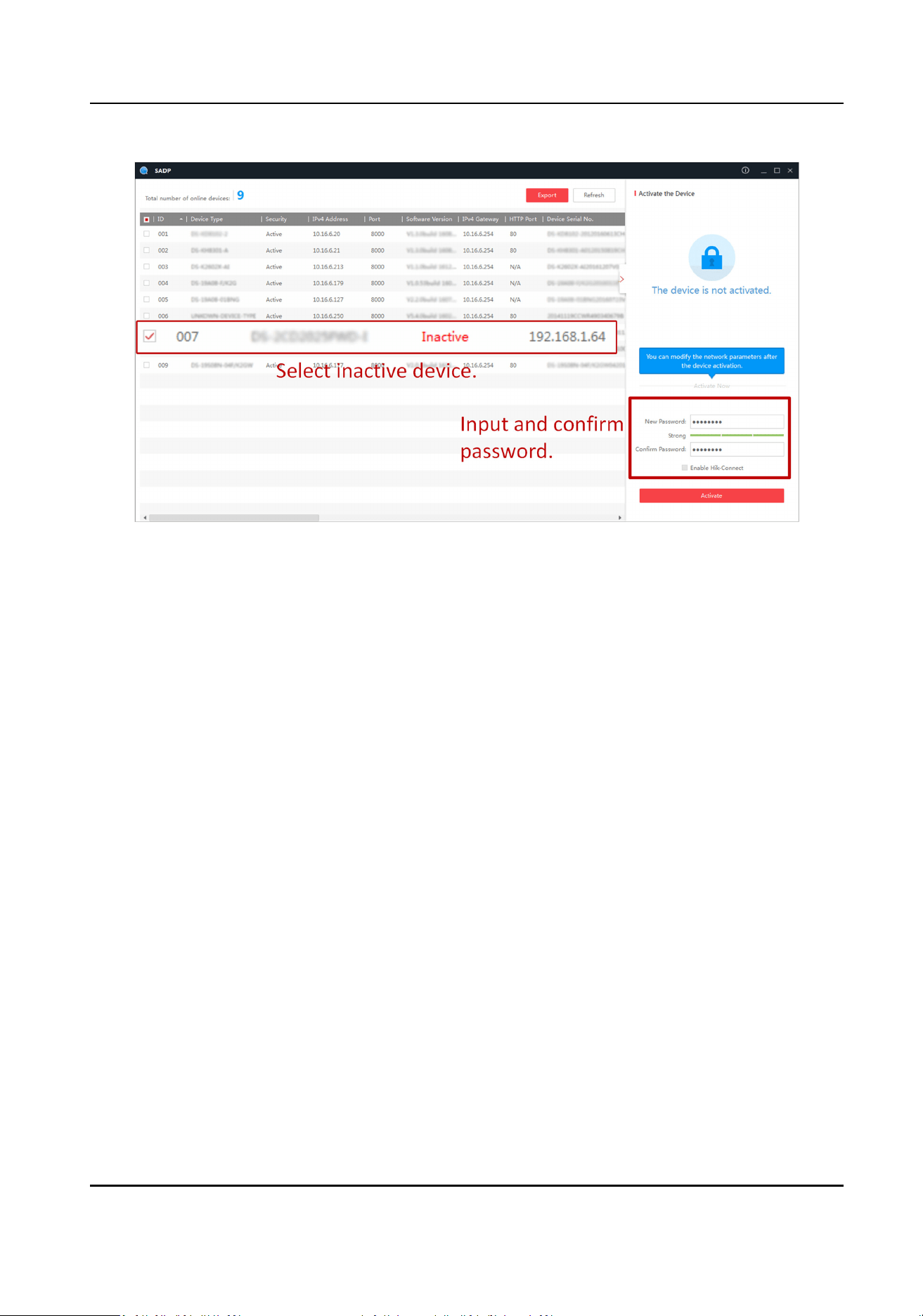
Figure 2-1 Acvate via SADP
Status of the device becomes Acve aer successful acvaon.
5.
Modify IP address of the device.
1) Select the device.
2) Change the device IP address to the same network segment as your computer by either
modifying the IP address manually or checking Enable DHCP (Dynamic Host
Conguraon
Protocol).
3) Enter the admin password and click Modify to
acvate your IP address modicaon.
2.1.3
Acvate via Web Browser
Use web browser to acvate the device. For the device with the DHCP enabled by default, use
SADP soware or client soware to acvate the device.
Before You Start
Ensure the device and the computer are in the LAN with the same network segment.
Steps
1.
Change the IP address of your computer to the same network segment as the device.
2.
Open the web browser, and enter the default IP address of the device to enter the
acvaon
interface.
3.
Create and conrm the admin password.
Auxiliary Care Radar User Manual
3

Cauon
STRONG PASSWORD RECOMMENDED-We highly recommend you create a strong password of
your own choosing (using a minimum of 8 characters, including upper case leers, lower case
leers, numbers, and special characters) in order to increase the security of your product. And
we recommend you reset your password regularly, especially in the high security system,
reseng the password monthly or weekly can beer protect your product.
4.
Click OK to complete acvaon.
5.
Go to the network sengs interface to modify IP address of the device.
2.2 Login
You can log in to the device via web browser for further operaons such as live view and local
conguraon.
Before You Start
Connect the device to the network directly, or via a switch or a router.
Steps
1.
Open the web browser, and enter the IP address of the device to enter the login interface.
2.
Enter User Name and Password.
3.
Click Login.
4.
Download and install appropriate plug-in for your web browser. Follow the
installaon prompts
to install the plug-in.
5.
Reopen the web browser
aer the installaon of the plug-in and repeat steps 1 to 3 to login.
6.
Oponal: Click Logout on the upper right corner of the interface to log out of the device.
Auxiliary Care Radar User Manual
4
Chapter 3 Radar Detecon
Enter a short descripon of your concept here (oponal).
This is the start of your concept.
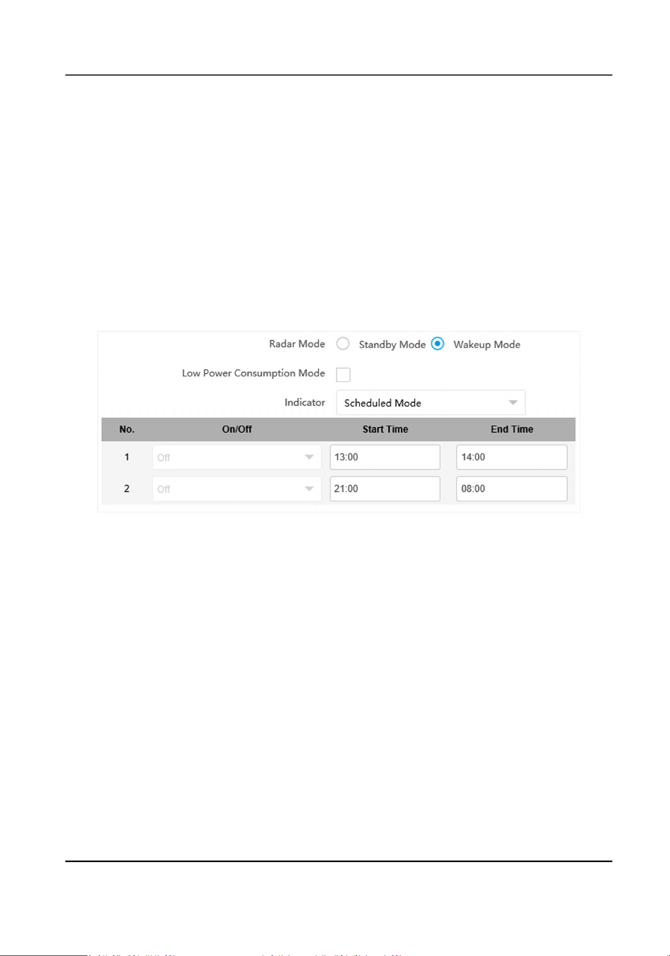
3.1 Set Radar Mode
Set radar mode according to the actual needs.
Steps
1.
Go to
Conguraon → System → System Sengs → Radar .
Figure 3-1 Set Radar Mode
2.
Select Radar Mode according to the actual needs.
Standby Mode
The radar is not
detecng.
Wakeup Mode
The radar is detecng.
3.
Oponal: Check Low Power Consumpon Mode and set Interval according to the actual needs.
If no human body is detected
aer the set Interval, the radar will automacally switch to
Standby Mode and detect according to the set Interval.
4.
Set the indicator mode.
-
Scheduled Mode: The indicator will be turned on/o according to the set Start Time and End
Time.
-
Manual Switch: Turn on/o the indicator manually.
5.
Click Save.
Auxiliary Care Radar User Manual
5
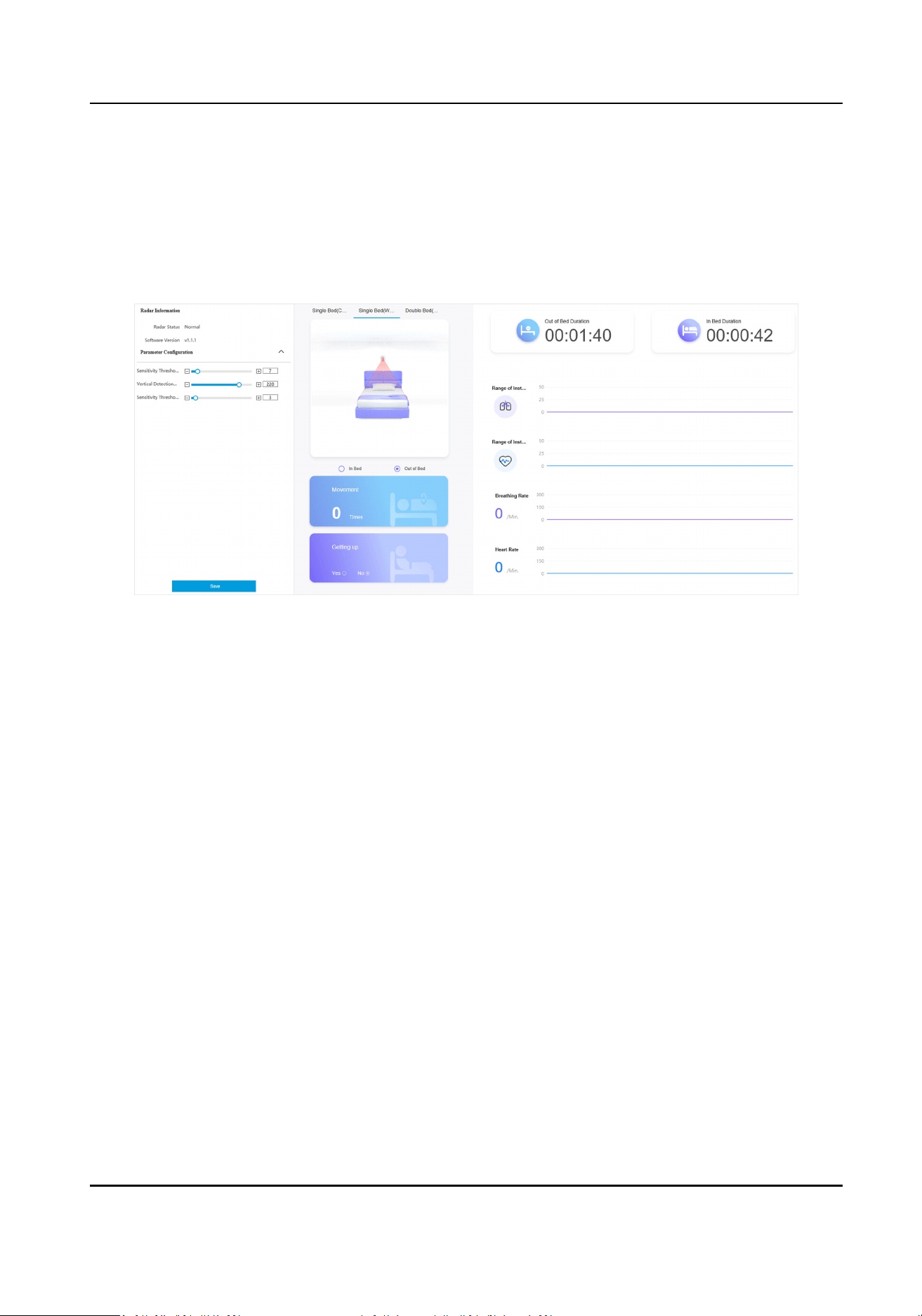
3.2 Set Detecon Parameters
Set radar detecon parameters according to the actual needs and installaon environment.
Steps
1.
Click Vital Sign Monitoring.
Figure 3-2 Set Detecon Parameters
2.
View the radar informaon.
Radar Status
The current radar status. The radar can be normally used in normal status. If the radar is in
upgrading status, do not reboot the device.
Soware Version
The soware version of the radar.
3.
Set the radar
detecon parameters.
Sensivity Threshold of Human Body Detecon
The higher the value is, the less sensive the detecon will be. The default value is
recommended.
Vercal Detecon Distance
The distance between the device and bed.
Sensivity Threshold of Body Detecon
The higher the value is, the less sensive the detecon will be. The default value is
recommended.
4.
Click Save.
5.
Select the
installaon mode according to the actual environment.
Auxiliary Care Radar User Manual
6

Result
The real-me detecon result will be displayed on the page.
Auxiliary Care Radar User Manual
7

Chapter 4 Storage
4.1 Set SDK Listening
The SDK listening can be used to receive the uploaded informaon of the device arming alarm.
Before You Start
The listening service has been enabled for the SDK listening, and the network communicaon with
the device is normal.
Steps
1.
Go to
Conguraon → Network → Data Connecon → SDK Listening .
2.
Check Enable SDK Listening.
3.
Set IP Address/Domain and Port if you need to upload the alarm informaon.
4.
Click Save.
4.2 Set ISAPI Listening
ISAPI listening and SDK listening are mutually exclusive protocols.
Before You Start
The listening service has been enabled for the ISAPI host, and the network communicaon with
the device is normal.
Steps
1.
Go to
Conguraon → Network → Data Connecon → ISAPI Listening .
2.
Check Enable ISAPI Listening.
3.
Set ANPR IP/Domain, ANPR Port, and Host URL.
4.
Click Save.
Auxiliary Care Radar User Manual
8
Chapter 5 Network Conguraon
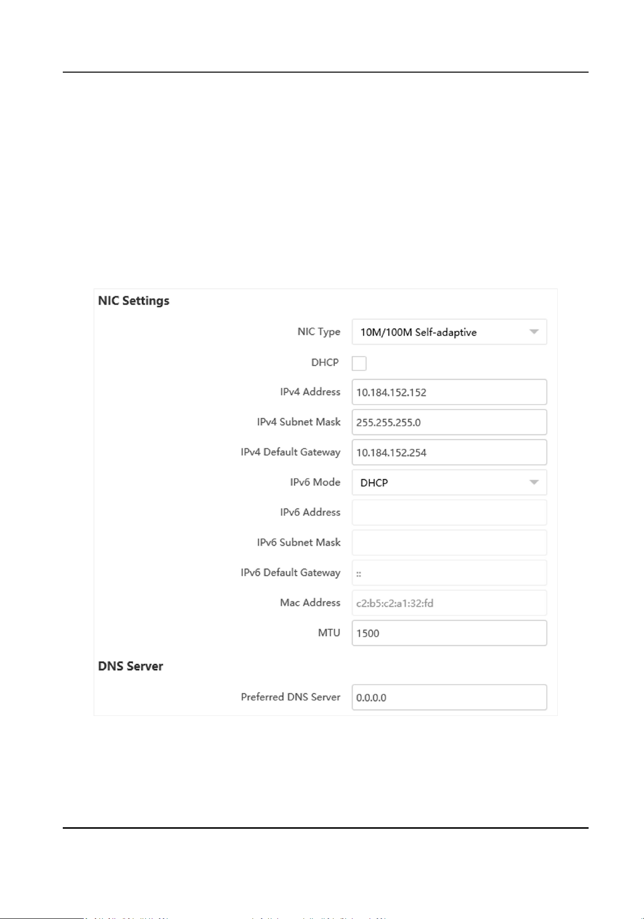
5.1 Set IP Address
IP address must be properly congured before you operate the device over network. IPv4 and IPv6
are both supported. Both versions can be congured simultaneously without conicng to each
other.
Steps
1.
Go to
Conguraon → Network → Network Parameters → Network Interface .
Figure 5-1 Set IP Address
2.
Set network parameters.
NIC Type
Auxiliary Care Radar User Manual
9
Select a NIC (Network Interface Card) type according to your network condion.
IPv4
Two modes are available.
DHCP
The device automacally gets the IP parameters from the network if you check DHCP. The
device IP address is changed aer enabling the funcon. You can use SADP to get the device
IP address.
Note
The network that the device is connected to should support DHCP (Dynamic Host
Conguraon Protocol).
Manual
You can set the device IP parameters manually. Enter IPv4 Address, IPv4 Subnet Mask, and
IPv4 Default Gateway.
IPv6
Three IPv6 modes are available.
Route
Adversement
The IPv6 address is generated by combining the route adversement and the device Mac
address.
Note
Route adversement mode requires the support from the router that the device is
connected to.
DHCP
The IPv6 address is assigned by the server, router, or gateway.
Manual
Enter IPv6 Address, IPv6 Subnet Mask, and IPv6 Default Gateway. Consult the network
administrator for required
informaon.
MTU
It stands for maximum transmission unit. It is the size of the largest protocol data unit that
can be communicated in a single network layer
transacon.
The valid value range of MTU is 1280 to 1500.
DNS
It stands for domain name server. It is required if you need to visit the device with domain
name. And it is also required for some
applicaons (e.g., sending email). Set Preferred DNS
Address properly if needed.
3.
Click Save.
Auxiliary Care Radar User Manual
10

5.2 Set Wi-Fi
Set Wi-Fi parameters if you want to connect the device to the network via Wi-Fi.
Steps
1.
Go to Conguraon → Network → Network Parameters → Wi-Fi .
2.
Select Wi-Fi Mode as Wi-Fi.
3.
Click Search and select Wi-Fi to connect in the Wi-Fi list.
4.
Select Security Mode and
Encrypon Type according to the actual needs.
5.
Enter Key.
6.
Click Save.
7.
Oponal: If you want to edit the IP address connected to the Wi-Fi to make it convenient to
access to the device via the IP address of WLAN, set the IP address of WLAN.
1) Select IP Address Type as
Stac IP.
2) Enter IP Address, Subnet Mask, Route Addressetc.
3) Click Set.
8.
Oponal: Click Refresh to view the Wi-Fi connecon status.
5.3 Set Wi-Fi AP
The device can be set as a hotspot to share network to other devices.
Steps
1.
Go to Conguraon → Network → Network Parameters → Wi-Fi .
2.
Select Wi-Fi Mode as Wi-Fi Hotspot.
3.
Enable AP Broadcast or WLAN Hotspot.
AP Broadcast
Once enabled, other devices are able to detect the SSID of the device.
WLAN Hotspot
Enable it to share the device's internet
connecon. Other devices can access to internet via
joining the hotspot.
4.
Set Wi-Fi hotspot parameters.
1) Enter SSID (hotspot name).
2) Select Security Mode and
Encrypon Type.
3) Set Key.
5.
Check DHCP, and enter an IP address from the address pool that allows
automac obtaining.
Note
IP address and TCP/IP address have to be in dierent network segments.
6.
Oponal: Set DNS server address if you need to visit the device with domain name.
7.
Click Save.
Auxiliary Care Radar User Manual
11
5.4 Connect to Plaorm
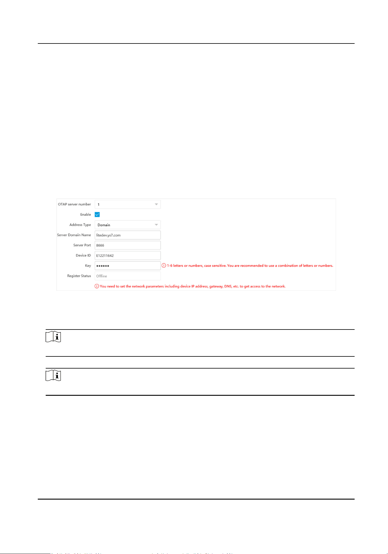
5.4.1 Connect to OTAP
The device can be accessed to the maintenance plaorm via OTAP protocol, in order to search and
acquire device informaon.
Before You Start
Ensure the device can communicate with the
plaorm normally.
Steps
1.
Go to Conguraon → Network → Data Connecon → OTAP .
2.
Check Enable.
Figure 5-2 Connect to OTAP
3.
Select Address Type.
4.
Enter the server IP address/domain, port, and device ID.
Note
The device ID should be the same with the added one on the OTAP plaorm.
5.
Enter Key.
Note
Enter the same Key on the plaorm.
6.
Click Save.
What to do next
When the registraon status is online, you can add or manage the device via the plaorm
soware. Refer to its corresponding manual for details.
Auxiliary Care Radar User Manual
12

5.4.2 Connect to Hik-Connect
The device can be remotely accessed via Hik-Connect.
Before You Start
●
Connect the device to the Internet.
●
Set the IP address, subnet mask, gateway, and DNS server of the LAN.
Steps
1.
Go to
Conguraon → Network → Data Connecon → Hik-Connect Plaorm .
2.
Check Enable.
3.
Select Protocol Version.
4.
Oponal: Check Custom to enter the deployed server IP address.
5.
Use the Hik-Connect mobile client to scan the QR to add the device.
6.
Click Save.
Note
Check the network connecon if the Register Status is Oine.
What to do next
You can access and manage the added device via Hik-Connect.
5.5 Set DDNS
You can use the Dynamic DNS (DDNS) for network access. The dynamic IP address of the device can
be mapped to a domain name resoluon server to realize the network access via domain name.
Before You Start
●
Register the domain name on the DDNS server.
●
Set the LAN IP address, subnet mask, gateway, and DNS server parameters.
●
Complete port mapping. The default ports are 80, 8000, and 554.
Steps
1.
Go to
Conguraon → Network → Network Parameters → DDNS .
2.
Check Enable DDNS.
Auxiliary Care Radar User Manual
13
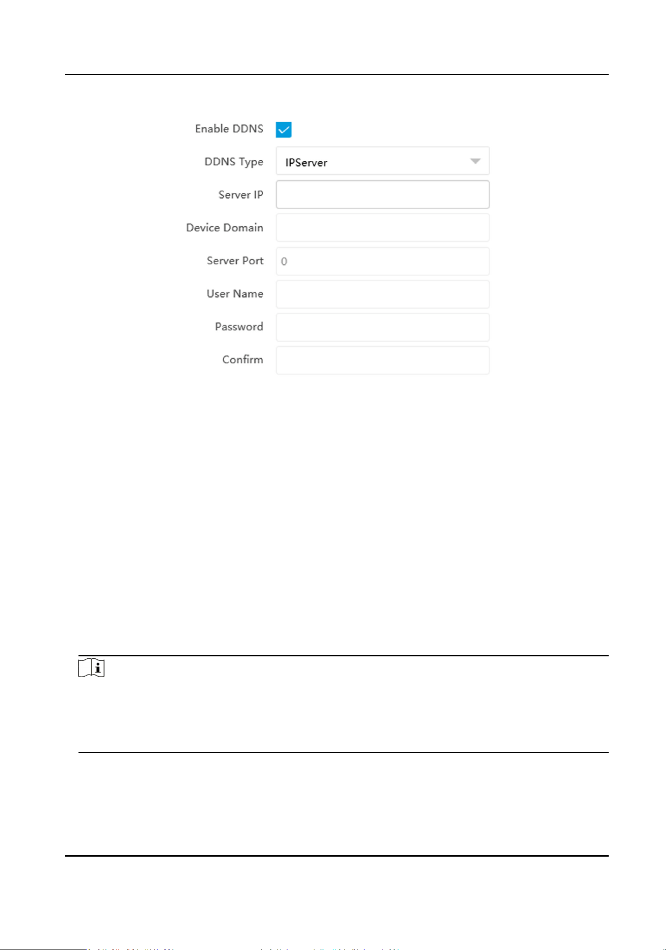
Figure 5-3 Set DDNS
3.
Enter the server address, domain, and other informaon.
4.
Click Save.
5.
Oponal: Enter the domain name in the browser address bar to access the device.
5.6 Set SNMP
You can set the SNMP network management protocol to get the alarm event and excepon
messages in network transmission.
Before You Start
Download the SNMP soware and manage to receive the device informaon via SNMP port.
Steps
1.
Go to
Conguraon → Network → Network Parameters → SNMP .
2.
Check Enable SNMPv1/Enable SNMP v2c/Enable SNMPv3.
Note
●
The SNMP version you select should be the same as that of the SNMP soware.
●
Use dierent versions according to the security levels required. SNMP v1 is not secure and
SNMP v2 requires password for access. SNMP v3 provides encrypon and if you use the third
version, HTTPS protocol must be enabled.
3.
Set the SNMP parameters.
4.
Click Save.
Auxiliary Care Radar User Manual
14
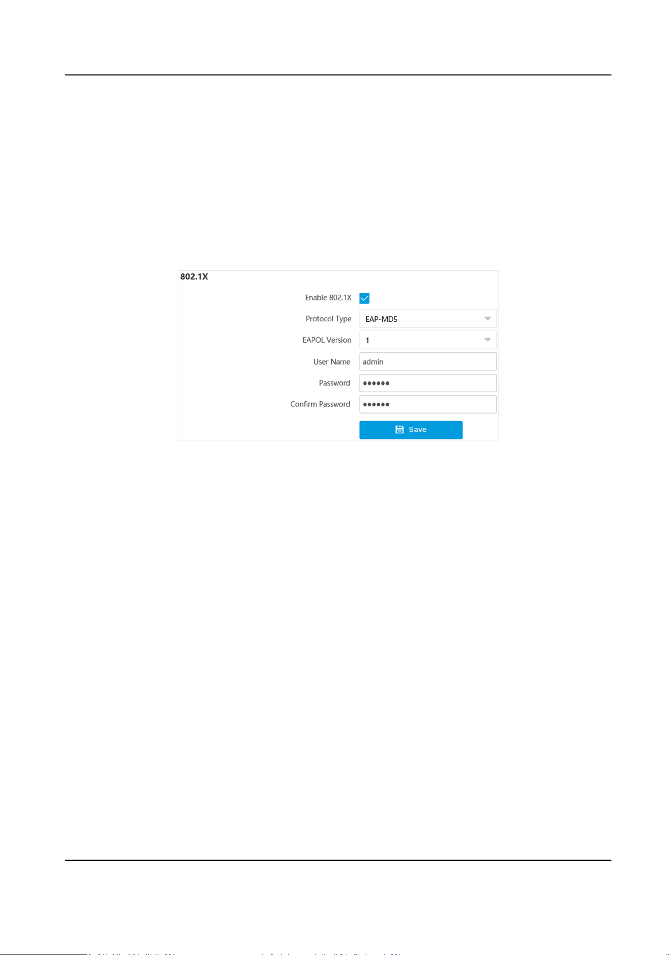
5.7 Set IEEE 802.1X
IEEE 802.1X is a port-based network access control. It enhances the security level of the LAN/
WLAN. When devices connect to the network with IEEE 802.1X standard, the authencaon is
needed.
Steps
1.
Go to
Conguraon → Network → Network Parameters → 802.1X .
2.
Check Enable 802.1X.
Figure 5-4 Set IEEE 802.1X
3.
Select Protocol Type and EAPOL Version.
Protocol Type
The
authencaon server must be congured. Register a user name and password for 802.1X
in the server in advance. Enter the user name and password for authencaon.
EAPOL Version
The EAPOL version must be idencal with that of the router or the switch.
4.
Enter User Name and Password registered in the server.
5.
Conrm the password.
6.
Click Save.
5.8 Set Port
The device port can be
modied when the device cannot access the network due to port conicts.
Steps
1.
Go to
Conguraon → Network → Network Parameters → Port .
2.
You can view and edit the port.
HTTP Port
Auxiliary Care Radar User Manual
15
It refers to the port through which the browser accesses the device. For example, when the
HTTP Port is modied to 81, you need to enter hp://192.168.1.64:81 in the browser for
login.
HTTPS Port
It refers to the port through which the browser accesses the device, but cercate
vericaon is needed.
SDK Port
It refers to the port through which the client adds the device.
SADP Port
It refers to the port through which the SADP
soware searches the device.
3.
Click Save.
Note
●
Aer eding the port, access to the device via the new port.
●
Reboot the device to bring the new sengs into eect.
Auxiliary Care Radar User Manual
16

Chapter 6 Excepon Alarm
Set excepon alarm when the network is disconnected, the IP address is conicted, etc.
Steps
1.
Go to
Conguraon → Event → Alarm Linkage → Excepon .
2.
Select the excepon type(s) according to the actual needs.
3.
Click Save.
Auxiliary Care Radar User Manual
17
Chapter 7 Safety Management
7.1 Manage User
The administrator can add, modify, or delete other accounts, and grant dierent permissions to
dierent user levels.
Steps
1.
Go to Conguraon → System → User Management .
2.
Select Password Level.
The password level of the added user should conform to the selected level.
3.
Add a user.
1) Click Add.
2) Enter User Name and select Type.
3) Enter Admin Password, New Password, and
conrm the password.
Cauon
To increase security of using the device on the network, please change the password of your
account regularly. Changing the password every 3 months is recommended. If the device is
used in high-risk environment, it is recommended that the password should be changed every
month or week.
4) Click OK.
4.
Oponal: You can do the following operaons.
Edit the user
informaon Click to edit the user informaon.
Delete the user Click to delete the user.
7.2 Enable User Lock
To raise the data security, you are recommended to lock the current IP address.
Steps
1.
Go to Conguraon → System → Security → Security Service → Soware .
2.
Check Enable User Lock.
3.
Click Save.
Result
When the mes you entered incorrect passwords have reached the limit, the current IP address
will be locked
automacally.
Auxiliary Care Radar User Manual
18

7.3 Install Authorized Cercate
If the demand for external access security is high, you can create and install authorized cercate
via HTTPS protocol to ensure the data transmission security.
Steps
1.
Go to Conguraon → Network → Network Parameters → HTTPS .
2.
Select Create
cercate request rst and connue the installaon.
3.
Click Create.
4.
Follow the prompt to enter Country/Region, Domain/IP, Validity, and other parameters.
5.
Click Download to download the
cercate request and submit it to the trusted authority for
signature.
6.
Import
cercate to the device.
-
Select Signed
cercate is available, start the installaon directly. Click Browse and Install to
import the cercate to the device.
-
Select Create the cercate request rst and connue the installaon. Click Browse and
Install to import the cercate to the device.
7.
Click Save.
7.4 Create and Install Self-signed
Cercate
HTTPS is a network protocol that enables encrypted transmission and identy authencaon,
which improves the security of remote access.
Steps
1.
Go to Conguraon → Network → Network Parameters → HTTPS .
2.
Select Create Self-signed
Cercate.
3.
Click Create.
4.
Follow the prompt to enter Country/Region, Domain/IP, Validity, and other parameters.
5.
Click OK.
Result
The device will install the self-signed cercate by default.
7.5 Set SSH
To raise network security, disable SSH service. The
conguraon is only used to debug the device
for the professionals.
Steps
1.
Go to
Conguraon → System → Security → Security Service → Soware .
2.
Disable SSH Service.
Auxiliary Care Radar User Manual
19

3.
Click Save.
7.6 Set IP Address Filtering
You can set the IP addresses allowable and not allowable to access the device.
Steps
1.
Go to Conguraon → System → Security → Security Sengs .
2.
Check Enable IP Address Filtering.
3.
Set Filtering Mode.
Blocklist Mode
The added IP addresses are not allowed to access the device.
Allowlist Mode
The added IP addresses are allowed to access the device.
4.
Click Add, enter the IP address, and click OK.
Note
The IP address only refers to the IPv4 address.
5.
Oponal: Edit, delete, or clear the added IP addresses.
6.
Click Save.
7.7 Set Timeout Logout
You can improve network access security by seng meout logout.
Steps
1.
Go to Conguraon → System → Security → Security Service → Timeout Logout .
2.
Enable
meout logout for stac page.
3.
Set Max. Timeout.
4.
Click Save.
Result
When the page stac me exceeds the set me, the device will automacally log out.
7.8 Set Password Validity Period
You can improve network access security by seng password validity period.
Steps
1.
Go to Conguraon → System → Security → Security Service → Password Validity Period .
2.
Select Validity Type.
Auxiliary Care Radar User Manual
20

-
Select Permanent. The password will be permanently valid.
-
Select Daily and set Password Expiry Time. It will prompt you that the password is expired
according to the set password expiry me, and you need to set the new password.
3.
Click Save.
Auxiliary Care Radar User Manual
21

Chapter 8 Maintenance
8.1 View Device Informaon
Basic Informaon and Algorithms Library Version
Go to Conguraon → System → System Sengs → Basic Informaon to view the basic
informaon of the device.
You can edit Device Name and Device No. The device No. is used to control the device. It is
recommended to reserve the default value.
Device Status
Go to Conguraon → System → System Sengs → Device Status to view the device status.
8.2 Log
8.2.1 Enable System Log Service
The security audit logs refer to the security operaon logs. You can search and analyze the security
log les of the device so as to nd out the illegal intrusion and troubleshoot the security events.
Security audit logs can be saved on device internal storage. The log will be saved every half hour
aer device boong. Due to limited storage space, you are recommended to save the logs on a log
server.
Steps
1.
Go to Conguraon → System → Security → Security Service → Log Audit Service .
2.
Enable system log service.
3.
Enter IP Address and Port of the log server.
4.
Click Save.
Result
The device will upload the security audit logs to the log server regularly.
8.2.2 Enable Log According to Module
You can enable the log according to the module for debugging.
Steps
1.
Go to Conguraon → System → Maintenance → Debug → Log .
2.
Check the module(s) according to your needs.
Auxiliary Care Radar User Manual
22
3.
Click Save.
8.3 Upgrade
Upgrade the system when you need to update the device version.
Before You Start
Prepare the upgrade le. If the upgrade le is a compressed package, it needs to be decompressed
into the .dav format.
Steps
1.
Go to
Conguraon → System → Maintenance → Upgrade & Maintenance → Upgrade .
2.
Click Browse to select the upgrade le.
3.
Click Upgrade.
4.
Click OK in the popup window.
Note
The upgrade process will take 1 to 10 minutes. Do not cut o the power supply.
Result
The device will reboot automacally aer upgrade.
8.4 Reboot
When the device needs to be rebooted, reboot it via the soware instead of cung o the power
directly.
Steps
1.
Go to Conguraon → System → Maintenance → Upgrade & Maintenance → Device
Maintenance .
2.
Click Reboot.
3.
Click OK to reboot the device.
Note
You can also click Reboot on the upper right corner of the page to reboot the device.
8.5 Restore Parameters
When the device is abnormal caused by the incorrect set parameters, you can restore the
parameters.
Auxiliary Care Radar User Manual
23
Steps
1.
Go to Conguraon → System → Maintenance → Upgrade & Maintenance → Device
Maintenance .
2.
Select the
restoraon mode.
-
Click Restore and click OK. Then the parameters except the IP parameters, user parameters,
and the saved parameters will be restored to the default sengs.
-
Click Restore Factory Sengs and click OK to restore all the parameters to the factory
sengs.
3.
Click OK.
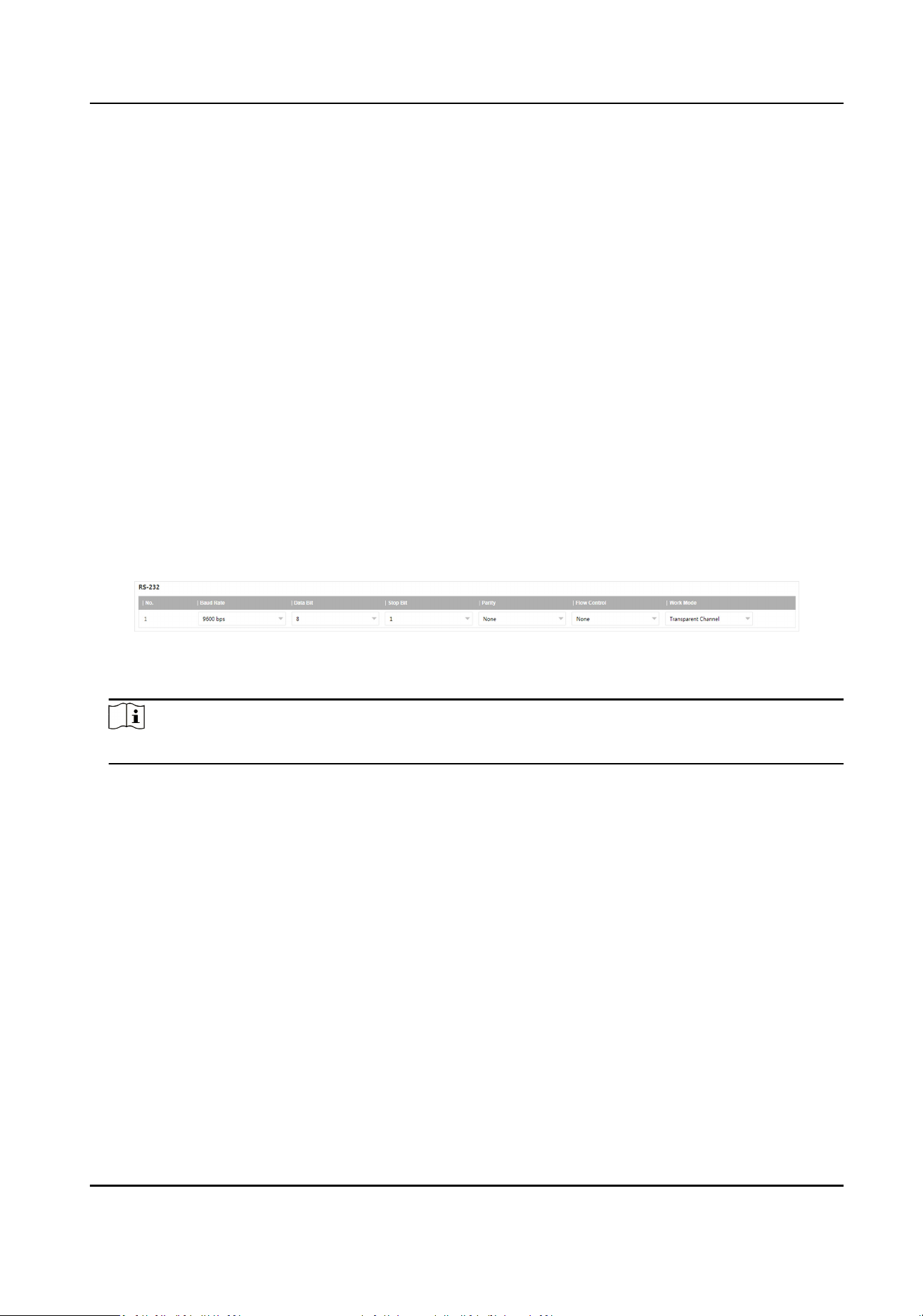
8.6 Set Serial Port
Set RS-232 parameters if you need to debug the device via RS-232 serial port.
Before You Start
The debugging device has been connected via the RS-232 serial port.
Steps
1.
Go to Conguraon → System → System Sengs → Serial Port .
Figure 8-1 Set RS-232
2.
Set Baud Rate, Data Bit, Stop Bit, etc.
Note
The parameters should be same with those of the connected device.
3.
Select Work Mode.
Console
Select it when you need to debug the device via RS-232 serial port.
Transparent Channel
Select it, and the network command can be
transmied to RS-232 control command via the
RS-232 serial port.
Narrow Bandwidth Transmission
Reserved.
4.
Click Save.
8.7 Synchronize Time
Synchronize the device me when it is inconsistent with the actual me.
Auxiliary Care Radar User Manual
24

Steps
1.
Go to Conguraon → System → System Sengs → Time Sengs .
2.
Select Time Zone.
3.
Select Sync Mode.
NTP Synchronizaon
Select it to synchronize the device me with that of the NTP server. Set Server IP, NTP Port,
and Interval. Click NTP Test to test if the connecon between the device and the server is
normal.
Manual
Synchronizaon
Select it to synchronize the device me with that of the computer. Set me manually, or
check Sync. with computer me.
SDK
If the remote host has been set for the device, select it to synchronize me via the remote
host.
ONVIF
Select it to synchronize me via the third-party device.
No
Select it to disable me synchronizaon.
All
Select it, and you can select any mode above.
4.
Click Save.
8.8 Set DST
If the region where the device is located adopts Daylight Saving Time (DST), you can set this
funcon.
Steps
1.
Go to
Conguraon → System → System Sengs → DST .
2.
Check Enable DST.
3.
Set Start Time, End Time, and DST Bias.
4.
Click Save.
8.9 Export Parameters
You can export the parameters of one device, and import them to another device to set the two
devices with the same parameters.
Steps
1.
Go to Conguraon → System → Maintenance → Upgrade & Maintenance → Data Export .
Auxiliary Care Radar User Manual
25
2.
Click Export aer Conguring Parameters.
3.
Set an encrypon password, conrm the password, and click OK.
Note
The password is used for imporng the conguraon le of the current device to other devices.
4.
Select the saving path, and enter the
le name.
5.
Click Save.
8.10 Import Conguraon File
Import the conguraon le of another device to the current device to set the same parameters.
Before You Start
Save the
conguraon le to the computer.
Steps
Cauon
Imporng conguraon le is only available to the devices of the same model and same version.
1.
Go to Conguraon → System → Maintenance → Upgrade & Maintenance → Advanced
Sengs → Data Import .
2.
Click Browse to select the
conguraon le.
3.
Click Import.
4.
Enter the password which is set when the
conguraon le is exported, and click OK.
5.
Click OK on the popup window.
Result
The parameters will be imported, and the device will reboot.
8.11 Export Debug File
The technicians can export the debug le to troubleshoot and maintain the device.
Steps
1.
Go to Conguraon → System → Maintenance → Upgrade & Maintenance → Data Export .
2.
Click Export
aer Debug File.
3.
Select the saving path, and enter the le name.
4.
Click Save.
Auxiliary Care Radar User Manual
26

8.12 Export Diagnosis Informaon
The technicians can export the diagnosis informaon to troubleshoot and maintain the device.
Steps
1.
Go to
Conguraon → System → Maintenance → Upgrade & Maintenance → Data Export .
2.
Click Export aer Diagnosis Informaon.
3.
Select the saving path, and enter the
le name.
4.
Click Save.
Auxiliary Care Radar User Manual
27
Appendix A. Communicaon Matrix and Device
Command
Scan the QR code below to get the
communicaon matrix of the device.
Scan the QR code below to get the device command.
Auxiliary Care Radar User Manual
28

UD31951B