
Security Radar
User Manual

Legal Informaon
User Manual
©2019 Hangzhou Hikvision Digital Technology Co., Ltd.
About this Manual
This Manual is subject to domesc and internaonal copyright protecon. Hangzhou Hikvision
Digital Technology Co., Ltd. ("Hikvision") reserves all rights to this manual. This manual cannot be
reproduced, changed, translated, or distributed, parally or wholly, by any means, without the
prior wrien permission of Hikvision.
Please use this user manual under the guidance of professionals.
Trademarks
and other Hikvision marks are the property of Hikvision and are
registered trademarks or the subject of applicaons for the same by Hikvision and/or its aliates.
Other trademarks menoned in this manual are the properes of their respecve owners. No right
of license is given to use such trademarks without express permission.
Disclaimer
TO THE MAXIMUM EXTENT PERMITTED BY APPLICABLE LAW, HIKVISION MAKES NO WARRANTIES,
EXPRESS OR IMPLIED, INCLUDING WITHOUT LIMITATION THE IMPLIED WARRANTIES OF
MERCHANTABILITY AND FITNESS FOR A PARTICULAR PURPOSE, REGARDING THIS MANUAL.
HIKVISION DOES NOT WARRANT, GUARANTEE, OR MAKE ANY REPRESENTATIONS REGARDING THE
USE OF THE MANUAL, OR THE CORRECTNESS, ACCURACY, OR RELIABILITY OF INFORMATION
CONTAINED HEREIN. YOUR USE OF THIS MANUAL AND ANY RELIANCE ON THIS MANUAL SHALL BE
WHOLLY AT YOUR OWN RISK AND RESPONSIBILITY.
REGARDING TO THE PRODUCT WITH INTERNET ACCESS, THE USE OF PRODUCT SHALL BE WHOLLY
AT YOUR OWN RISKS. HIKVISION SHALL NOT TAKE ANY RESPONSIBILITIES FOR ABNORMAL
OPERATION, PRIVACY LEAKAGE OR OTHER DAMAGES RESULTING FROM CYBER ATTACK, HACKER
ATTACK, VIRUS INSPECTION, OR OTHER INTERNET SECURITY RISKS; HOWEVER, HIKVISION WILL
PROVIDE TIMELY TECHNICAL SUPPORT IF REQUIRED.
SURVEILLANCE LAWS VARY BY JURISDICTION. PLEASE CHECK ALL RELEVANT LAWS IN YOUR
JURISDICTION BEFORE USING THIS PRODUCT IN ORDER TO ENSURE THAT YOUR USE CONFORMS
THE APPLICABLE LAW. HIKVISION SHALL NOT BE LIABLE IN THE EVENT THAT THIS PRODUCT IS USED
WITH ILLEGITIMATE PURPOSES.
IN THE EVENT OF ANY CONFLICTS BETWEEN THIS MANUAL AND THE APPLICABLE LAW, THE LATER
PREVAILS.
Security Radar User Manual
i
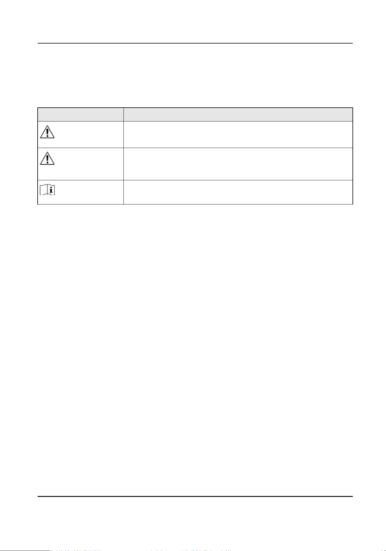
Symbol Convenons
The symbols that may be found in this document are dened as follows.
Symbol Descripon
Danger
Indicates a hazardous situaon which, if not avoided, will or could
result in death or serious injury.
Cauon
Indicates a potenally hazardous situaon which, if not avoided, could
result in equipment damage, data loss, performance degradaon, or
unexpected results.
Note
Provides addional informaon to emphasize or supplement
important points of the main text.
Security Radar User Manual
ii

Contents
Chapter 1 Access to Client Soware/Web Client ......................................................................... 1
Chapter 2 Acvaon ................................................................................................................... 2
2.1 Acvate Device via Client Soware ........................................................................................ 2
2.2 Acvate via SADP ................................................................................................................... 2
2.3 Acvate Device via Web Browser .......................................................................................... 4
Chapter 3 Wired Network Sengs .............................................................................................. 5
Chapter 4 Radar Sengs ............................................................................................................ 6
4.1 Add Map ................................................................................................................................ 6
4.2 Add the Radar to the Map ..................................................................................................... 7
4.3 Add Radar Zone ..................................................................................................................... 9
4.4 Add Trigger Line ................................................................................................................... 12
4.5 Other Auxiliary Funcons .................................................................................................... 13
Chapter 5 Camera Linkage Sengs ........................................................................................... 15
5.1 Set Speed Dome Inial Posion ........................................................................................... 15
5.2 Link the Camera to the radar ............................................................................................... 16
5.3 Link the Camera to the Zone ................................................................................................ 17
5.4 Enable Alarm Triggered Pop-up Image ................................................................................. 18
5.5 Calibrate Camera .................................................................................................................. 20
5.5.1 One Point Calibraon .................................................................................................. 24
5.5.2 Mulpoint Calibraon ................................................................................................. 27
5.6 Enable Camera Tracking ....................................................................................................... 29
5.7 Set Park Funcon for Linked Camera ................................................................................... 30
Chapter 6 Set Record and Storage Sengs ................................................................................ 32
6.1 Set Storage Sengs ............................................................................................................. 32
6.1.1 Set Storage Schedule via Storage Server ..................................................................... 32
6.1.2 Set Storage Schedule via NVR ..................................................................................... 33
Security Radar User Manual
iii

6.1.3 Set Tracking Strategy ................................................................................................... 33
Chapter 7 Alarm Sengs .......................................................................................................... 34
7.1 Alarm Center ........................................................................................................................ 34
7.2 Nocaon Push .................................................................................................................. 34
7.3 Set Zone ............................................................................................................................... 35
7.4 Set Alarm Output ................................................................................................................. 36
7.5 Set Trigger Line ..................................................................................................................... 37
7.6 Set Arming/Disarming Schedule .......................................................................................... 37
7.7 Set Moon Speed ................................................................................................................ 38
7.8 Video Tracking Switch Sengs ............................................................................................. 38
Chapter 8 Set Radar Advanced Funcon ................................................................................... 39
8.1 Set Master-slave Tracking Sengs ....................................................................................... 39
8.2 Set Detecon Angle and Range ............................................................................................ 39
8.3 Set Scene Mode and Sensivity ........................................................................................... 40
8.4 Set Frequency Range Sengs .............................................................................................. 41
Chapter 9 View Alarm Informaon ........................................................................................... 42
Chapter 10 System Management .............................................................................................. 43
10.1 Set Time ............................................................................................................................. 43
10.2 Manage User ...................................................................................................................... 43
10.3 System Maintenance .......................................................................................................... 44
10.4 View Device Informaon .................................................................................................... 45
10.5 Search Log .......................................................................................................................... 45
10.6 Enabling Remote Debugging .............................................................................................. 45
Appendix A. Radar Mounng Height Recommendaon ............................................................ 46
Appendix B. Formang Descripon ......................................................................................... 47
Appendix C. Indicator Descripon ............................................................................................ 48
Appendix D. FAQ ...................................................................................................................... 49
D.1 How to Achieve an Opmum Detecon Range? ................................................................. 49
Security Radar User Manual
iv

D.2 How to Solve the Problem that the Radar is not Shown in the Device List on the Radar
Page? ......................................................................................................................................... 49
D.3 How to Adjust the Sensivity to Avoid False Alarm? ........................................................... 49
D.4 How to Raise the Precision of Camera Tracking? ................................................................. 50
D.5 How to Solve the Problem that No Reference Point is on the Frame While Seng the Speed
Dome Inial Posion? ................................................................................................................ 50
D.6 What is the Reason that Failed to Draw a Zone Automacally? .......................................... 52
D.7 What Makes a Failed Arming? ............................................................................................. 52
D.8 Why Is It Required to Remove Reecve Objects from the Radar Area? ............................ 52
D.9 Why Is the Camera Unable to Track the Target? .................................................................. 52
D.10 Common Mistakes of Calibrang Camera ......................................................................... 52
Security Radar User Manual
v
Chapter 1 Access to Client Soware/Web Client
You can login the Client Soware or the web client to congure the device's parameters. You can
also congure the radar's network parameters, alarm, permission, system, log search via the web
client.
Note
You should acvate the device the rst me you access it to the network for safety reasons. For
details, see Device Acvaon.
Access to Client Soware
Download and install the iVMS-4200 client soware. Register to the soware and add device in
Control Panel → Device Management → Device for Management .
Note
• You should set the device port No. as 80.
• The user name and password when adding device are the acvaon user name and password.
Aer the device is completely added, click Remote Conguraon to enter the device conguraon
page. You can congure the device parameters in this page.
Access to Web Client
Aer the device is connected to the network, you can search the device IP address via the
iVMS-4200 client soware and the SADP soware. Input the searched IP address in the address bar
in the web page and press Enter. Use the acvaon user name and password to login. You can
congure the device parameters in the web page.
Security Radar User Manual
1
Chapter 2 Acvaon
In order to protect personal security and privacy and improve the network security level, you
should acvate the device the rst me you connect the device to a network.
2.1 Acvate Device via Client Soware
Before You Start
• Get the iVMS-4200 client soware from the supplied disk or the ocial website hp://
www.hikvision.com/en/ . Install the soware by following the prompts.
• The device and the PC that runs the soware should be in the same subnet.
Steps
1. Run the client soware.
2. Enter Device Management or Online Device.
3. Check the device status from the device list, and select an inacve device.
4. Click Acvate.
5. Create and conrm the admin password of the device.
Cauon
STRONG PASSWORD RECOMMENDED-We highly recommend you create a strong password of
your own choosing (using a minimum of 8 characters, including upper case leers, lower case
leers, numbers, and special characters) in order to increase the security of your product. And
we recommend you reset your password regularly, especially in the high security system,
reseng the password monthly or weekly can beer protect your product.
6. Click OK to start acvaon.
Device status will change to Acve aer successful acvaon.
7. Edit IP address of the device.
1) Select a device and click Modify Nenfo at Online Device.
2) Change the device IP address to the same subnet with your computer by either modifying
the IP address manually or checking DHCP.
3) Input the admin password of the device and click OK to complete modicaon.
2.2 Acvate via SADP
SADP is a tool to detect, acvate and modify the IP address of the device over the LAN.
Security Radar User Manual
2
Before You Start
• Get the SADP soware from the supplied disk or the ocial website hp://
www.hikvision.com/en/ , and install the SADP according to the prompts.
• The device and the PC that runs the SADP tool should be within the same subnet.
The following steps show how to acvate a device and modify its IP address. For batch acvaon
and IP addresses modicaon, refer to User Manual of SADP for details.
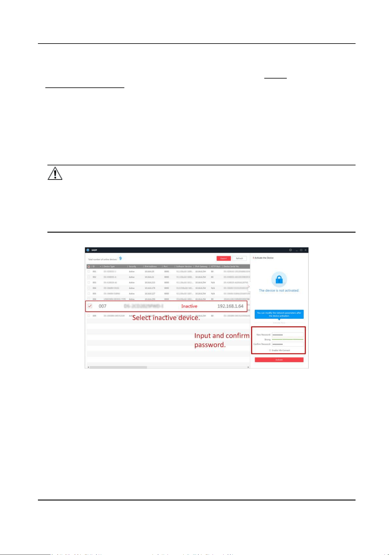
Steps
1. Run the SADP soware and search the online devices.
2. Find and select your device in online device list.
3. Input new password (admin password) and conrm the password.
Cauon
STRONG PASSWORD RECOMMENDED-We highly recommend you create a strong password of
your own choosing (using a minimum of 8 characters, including upper case leers, lower case
leers, numbers, and special characters) in order to increase the security of your product. And
we recommend you reset your password regularly, especially in the high security system,
reseng the password monthly or weekly can beer protect your product.
4. Click Acvate to start acvaon.
Status of the device becomes Acve aer successful acvaon.
5. Modify IP address of the device.
1) Select the device.
2) Change the device IP address to the same subnet as your computer by either modifying the
IP address manually or checking Enable DHCP.
3) Input the admin password and click Modify to acvate your IP address modicaon.
Security Radar User Manual
3
2.3 Acvate Device via Web Browser
Use web browser to acvate the device. Use SADP soware or PC client to search the online device
to get the IP address of the device, and acvate the device on the web page.
Before You Start
Make sure your device and your PC connect to the same LAN.
Steps
1. Open a web browser and input the IP address of the device.
Note
If you connect the device with the PC directly, you need to change the IP address of your PC to
the same subnet as the device. The default IP address of the device is 192.0.0.64.
2. Create and conrm the admin password.
Cauon
STRONG PASSWORD RECOMMENDED-We highly recommend you create a strong password of
your own choosing (using a minimum of 8 characters, including upper case leers, lower case
leers, numbers, and special characters) in order to increase the security of your product. And
we recommend you reset your password regularly, especially in the high security system,
reseng the password monthly or weekly can beer protect your product.
3. Click OK to complete acvaon.
4. Edit IP address of the device.
1) Enter IP address modicaon page.
2) Change IP address.
3) Save the sengs.
Security Radar User Manual
4
Chapter 3 Wired Network Sengs
You can set the device IP address and other network parameters.
Steps
Note
Funcons varied depending on the model of the device.
1. In the client soware, enter Device Management page.
2. Select the device in the Device for Management list, click Remote Conguraon.
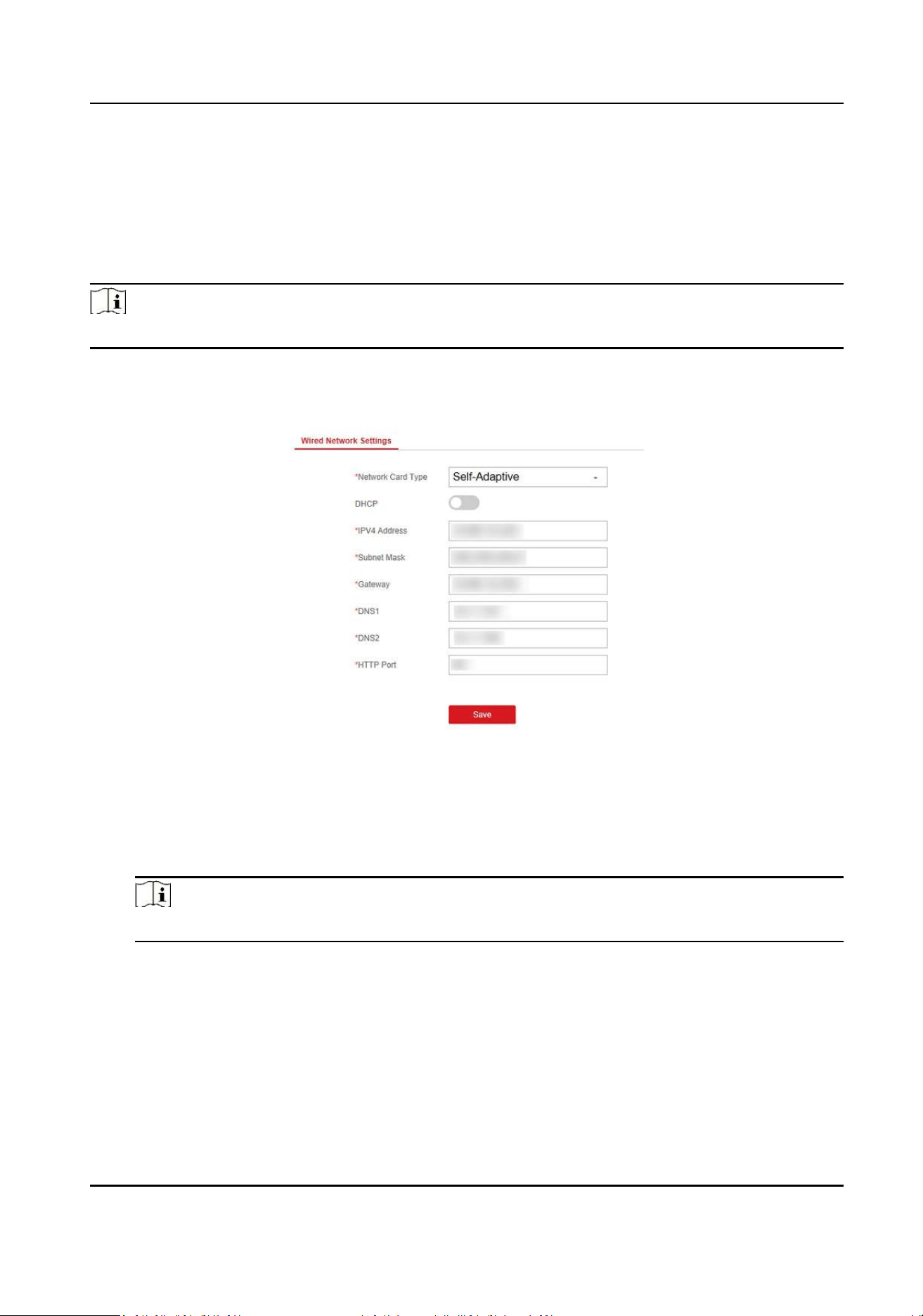
3. Click Communicaon Parameters → Wired Network Sengs to enter the page.
Figure 3-1 Wired Network Sengs Page
4. Set the parameters.
-
Automac Sengs: Enable DHCP and set the HTTP port.
-
Manual Sengs: Disabled DHCP and set IP Address, Subnet Mask, Gateway Address, DNS
Server Address.
Note
By default, the HTTP port is 80, which is not editable.
5. Oponal: Set correct DNS server address if the device needs to visit Hik-Connect server via a
domain name.
6. Set correct DNS server address if the device needs to visit server via a domain name.
7. Click Save.
Security Radar User Manual
5
Chapter 4 Radar Sengs
You can add zones, and set camera tracking parameters for the radar in the Radar module of the
client soware.
Click Control Panel → Modules Customizaon , check Radar, and click OK.
4.1 Add Map
Steps
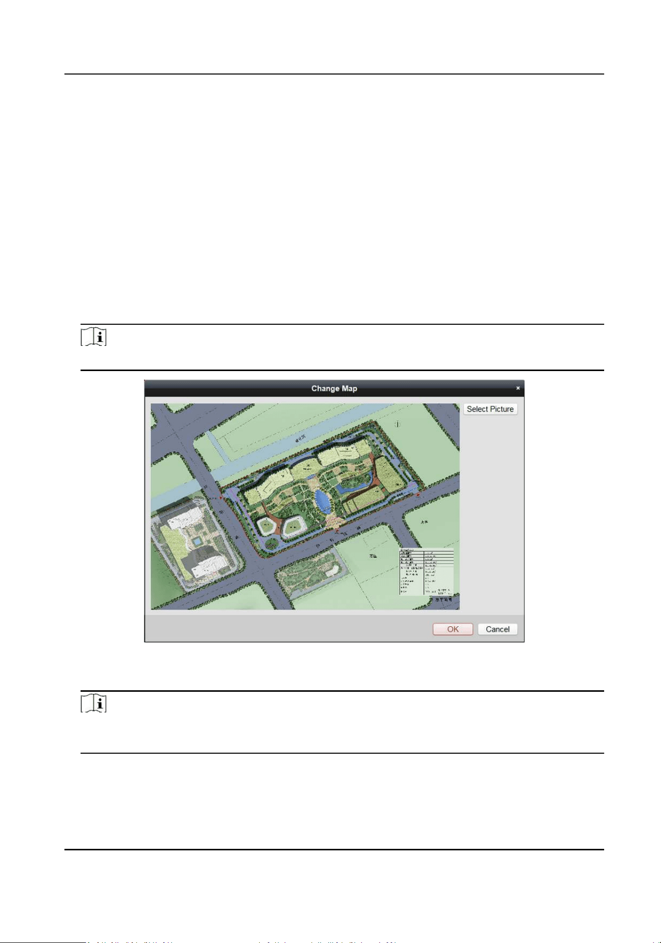
1. Click Control Panel → Radar to enter the radar page.
2. Click Select Picture to load a map.
Note
Supported picture formats: jpg/png/bmp.
Figure 4-1 Add a Map
3. Click OK.
Note
Aer the addion is complete, a prompt will pop up: You need to set the plong scale.
Connue?
4. Click OK in the popup window, or click ... → Edit The Scale to enter the page.
Security Radar User Manual
6
Note
Edit the scale will remove all radars on the map.
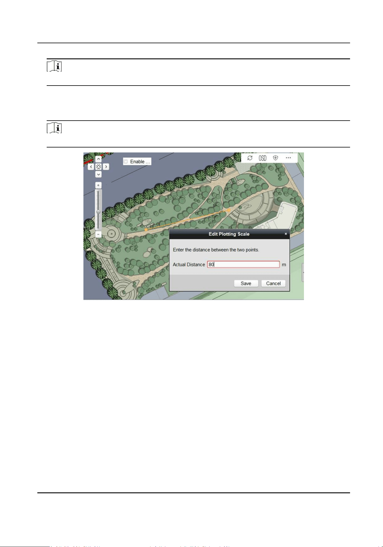
5. Click on the map to draw a straight line, select the end posion and click again to complete the
drawing.
6. Enter the actual distance between two points.
Note
The gray word is the predicted distance range of system, for reference only.
Figure 4-2 Edit Plong Scale
7. Click Save.
4.2 Add the Radar to the Map
Aer adding the map, you need to add a radar to the map for seng radar zones.
Before You Start
Make sure that you have added the radar (when adding the device, check Export to Group) to the
client soware, and add the map.
Steps
1. Expand the device group in the le list, and then click and drag the radar onto the map.
Security Radar User Manual
7
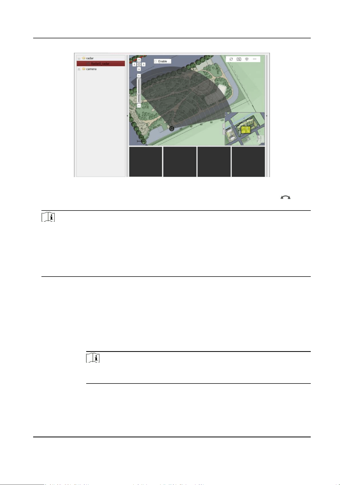
Figure 4-3 Add the Radar to the Map
2. Adjust the radar posion. Drag the radar to change the posion, and rotate and drag on
the arc side of the fan to rotate the direcon of the radar detecon area.
Note
• You can click the direcon buons in the upper le corner on the map or drag the yellow
slider in the lower right corner on the map to adjust the range of displayed map, and slide the
block on the zoom in/out bar on the zoom control strip on the le side of the map to adjust
the size of displayed map.
• Right click on the radar area (gray sector), you can click Delete to delete the radar area, and
click Arm or Disarm to start/stop the arming mode.
3. Right click in the radar area, select pin to x the radar area. Try to ensure that the posion and
direcon of the radar on the map are consistent with the actual installaon posion and
direcon of the radar.
4. Oponal: Right click on the radar area (the fan area) to open the radar sengs menu.
Menu Descripon
Delete Delete the radar from the map.
Arm Open the arming mode of the radar detecon area.
Note
If there is a target in the warning zone when arming, a prompt will appear:
There are targets in the zone, enable mandatory arming?, and click OK to arm.
Disarm Close the arming mode of the radar dectcon area.
Pin Fix the radar on the map.
Security Radar User Manual
8
Unpin Unlock the radar locaon, and then you can move the radar detecon area
On Watch Set the camera watch point for the radar.
Note
For more informaon, see Set Park Funcon for Linked Camera .
Aer enabling the radar park mode, the main radar will control the camera to
return to the set watch point when no target appears within 10 seconds in the
radar detecon area.
4.3 Add Radar Zone
Before You Start
You need to disarm the radar before the operaon. Right-click on the radar detecon area, and
click Disarm to disarm the radar.
Steps
1. In the client soware, click Control Panel → Radar to enter the page.
2. Oponal: Check Enable Auxiliary Funcon on the upper le corner of the map. The target track
will appear on the radar detecon area. You can draw a zone with reference to the track. The
track cleared when unchecked.
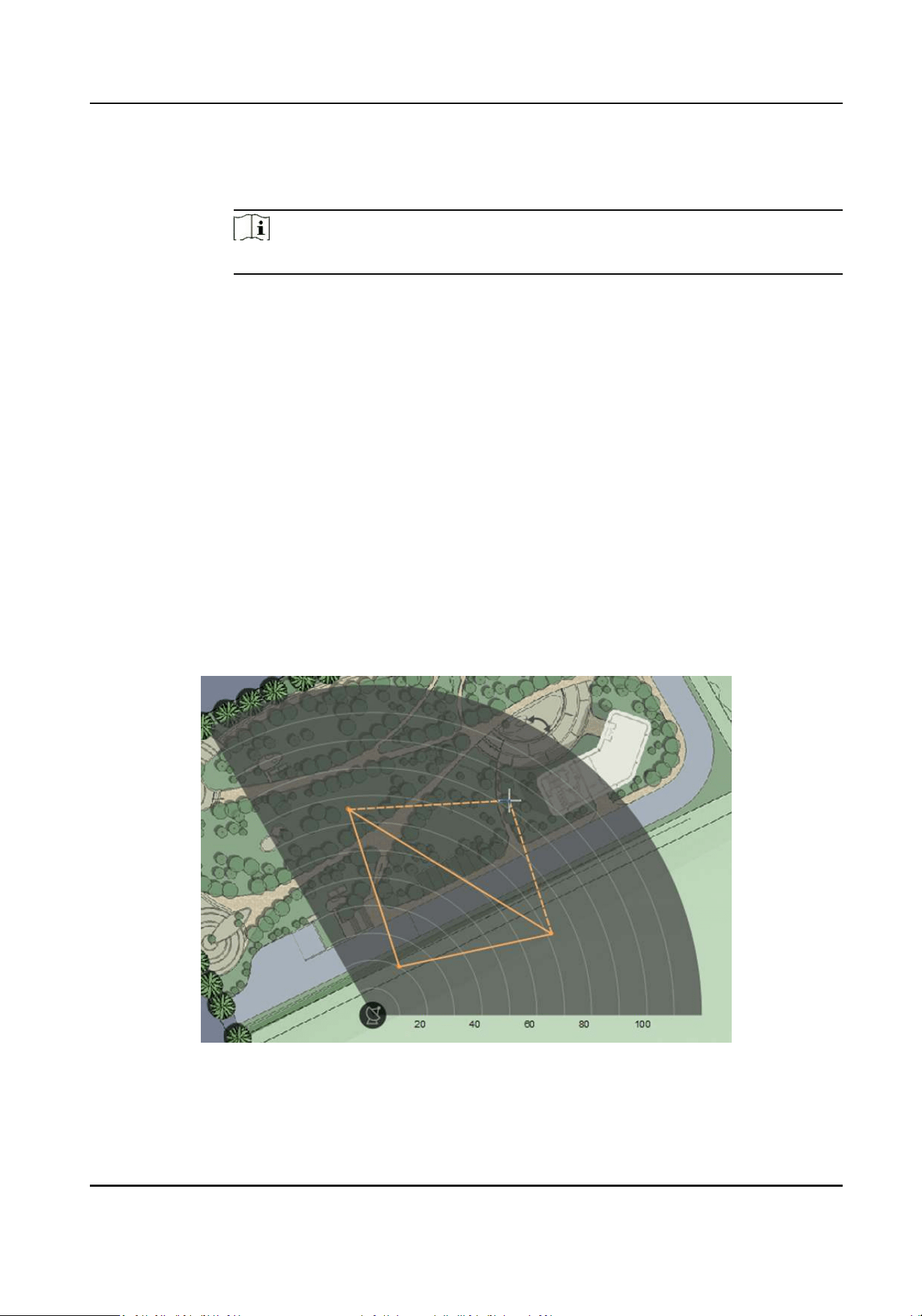
3. Click … → Draw Zone Manually , and click the mouse to draw a zone on the radar detecon
area.
Figure 4-4 Draw a Zone
Security Radar User Manual
9
Note
• Adding zones is a batch operaon. If you only add zones to one radar, you need to right-click
on the remaining radar detecon zones and click Cancel.
• Zones can overlap, but the relaonship between low priority and high priority should be
sased. Priority is: Disabled Zone>Warning Zone>Early Warning Zone. That is, Early Warning
Zone can contain Warning Zone and Disabled Zone, and Warning Zone can contain Disabled
Zone.
• If the size of the displayed radar area is too small, you can slide the block on the Zoom in/out
bar on the le to adjust the size of the displayed radar area.
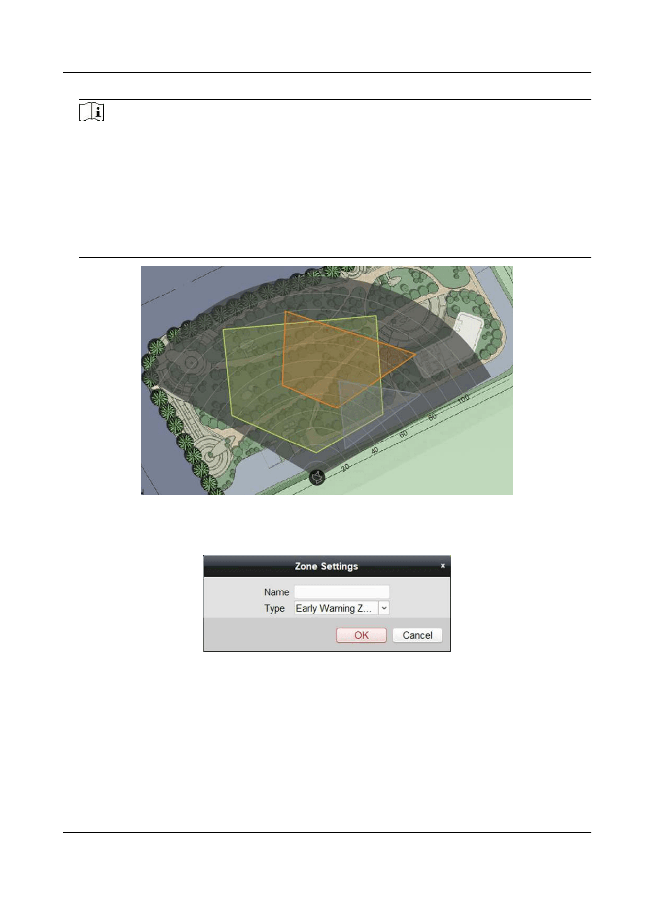
Figure 4-5 Overlap zones
4. Right-click to complete drawing, and the system will pop up a window. Enter the zone name,
and select Early Warning Zone, Warning Zone, or Disabled Zone as the zone type.
Figure 4-6 Zone Sengs
Security Radar User Manual
10
Note
• Early Warning Zone: When the zone is an early warning zone, target with potenal risks
entering the zone will be idened and alarmed, but the alarm track will not be stored. It is
green when the warning zone is not alarming and orange when the alarm is triggered.
• Warning Zone: When the zone is an warning zone, the target entering the zone will be
idened and alarm occurred. It is displayed in orange.
• Disabled Zone: When the zone is an disabled zone, the track of the target entering the zone
will be disabled. It is displayed in grey.
5. Click OK.
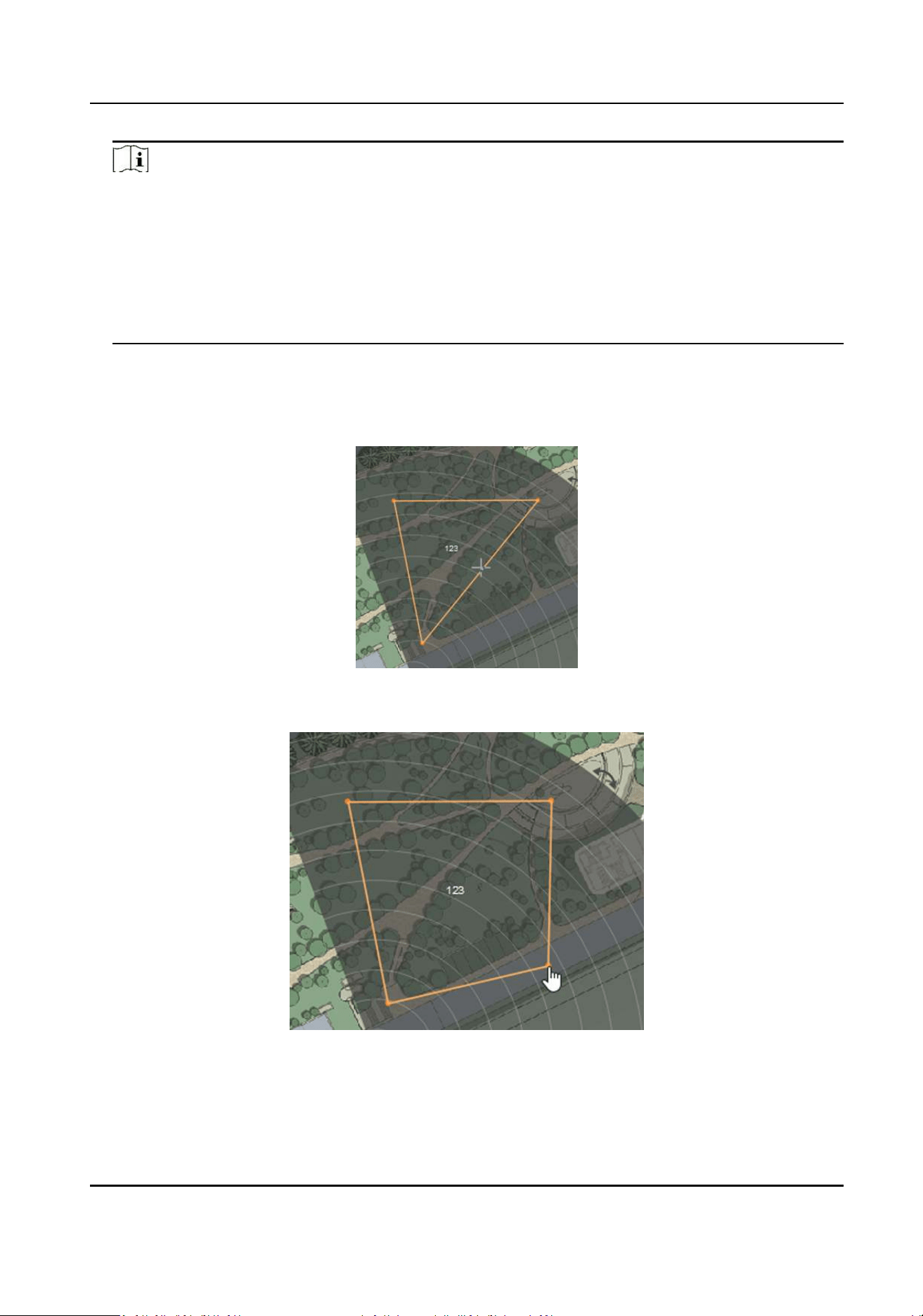
6. Oponal: Modify or delete the zone.
1) Right-click on the zone, select Edit.
2) Hovering over the edge of the zone will change the cursor to a cross, click to add a marker.
Figure 4-7 Add a Marker
3) Drag the marker to change the shape of the zone.
Figure 4-8 Drag a Marker
4) Hold to drag the zone.
Security Radar User Manual
11
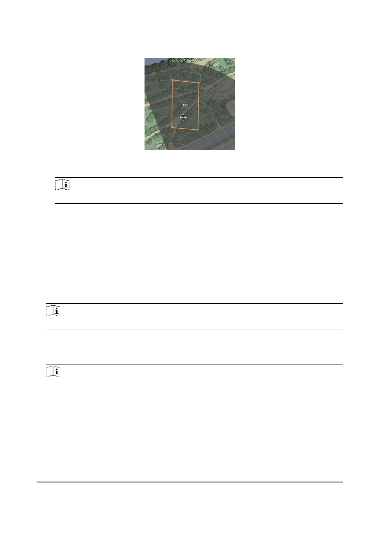
Figure 4-9 Drag the Zone
5) Right-click on the zone and select Exit the sengs mode.
Note
To delete a zone, right-click the zone in the edit state and select Delete.
4.4 Add Trigger Line
You need to draw at least one trigger line for the radar detecon area and set alarm rules.
Before You Start
• The radar is added to the map.
• Right-click on the radar detecon area, and click Disarm to disarm the radar.
Steps
1. In Radar page, click … → Draw Trigger Line .
Note
You can draw trigger line for all radars on the map.
2. Draw the trigger line.
1) Click on the radar detecon area to draw a trigger line.
2) Select Le -> Right, Le <- Right or Le <-> Right in the pop-up window.
Note
• Direcon determinaon: Set the starng point as the center of the circle, the trigger line is
clockwise to the right, and counterclockwise to the le.
• Up to 4 trigger lines can be drawn.
• Alarm rules: A single arrow -> indicates that the target triggers an alarm when it crosses the
trigger line in the direcon of the arrow; a double arrow <-> indicates that the target triggers
an alarm when it crosses the trigger line in any direcon.
Security Radar User Manual
12
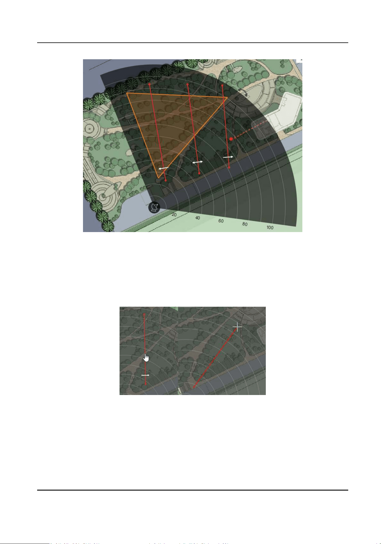
Figure 4-10 Draw a Trigger Line
3. Click Cancel to complete the drawing.
4. Oponal: Edit the trigger line: right-click on the trigger line.
-
Trigger Line: L1: Display the name of the trigger line.
-
Edit: The cursor hovering over the trigger line will becomes the palm of the hand. Hold to
move the gger line. The cursor hovering over the end of the trigger line will becomes a
cross. Click to adjust the posion of the trigger line.
Figure 4-11 Edit the Trigger Line
-
Set Rule: Select the trigger rule.
-
Delete: Delete the trigger line.
4.5 Other Auxiliary Funcons
Security Radar User Manual
13
Speed Dome Field of View
Note
Before using this funcon, you need to conrm that the speed dome has been calibrated and the
speed dome has an linked zone.
In Radar page, click … → Enable Speed Dome Field of View .
Aer turning on, you can see the target tracked by the currently linked speed dome.
Figure 4-12 Speed Dome Field of View
You can click ... → Disable Field of View to close the funcon.
OSD
In Radar page, click OSD → Open .
Aer turning on, the speed and distance of the target will be displayed on the radar.
Mandatory Tracking
Select the radar and click Remote Conguraon in the client soware, or enter the IP address of
the radar in the address bar of the web browser. Click Smart Rule Sengs → Video Tracking
Switch Sengs to enter the page.
Aer enabled, when you click a target track in the radar detecon area, the camera will mandatory
track the target.
Security Radar User Manual
14
Chapter 5 Camera Linkage Sengs
The radar can work with cameras such as speed dome and box camera for target tracking and
video recording.
5.1 Set Speed Dome Inial Posion
Set the inial posion of the speed dome to ensure the tracking accuracy.
Steps
1. Select a reference object about 50 m away from the speed dome. On the reference object,
select a reference point whose altude is the same as the speed dome's.
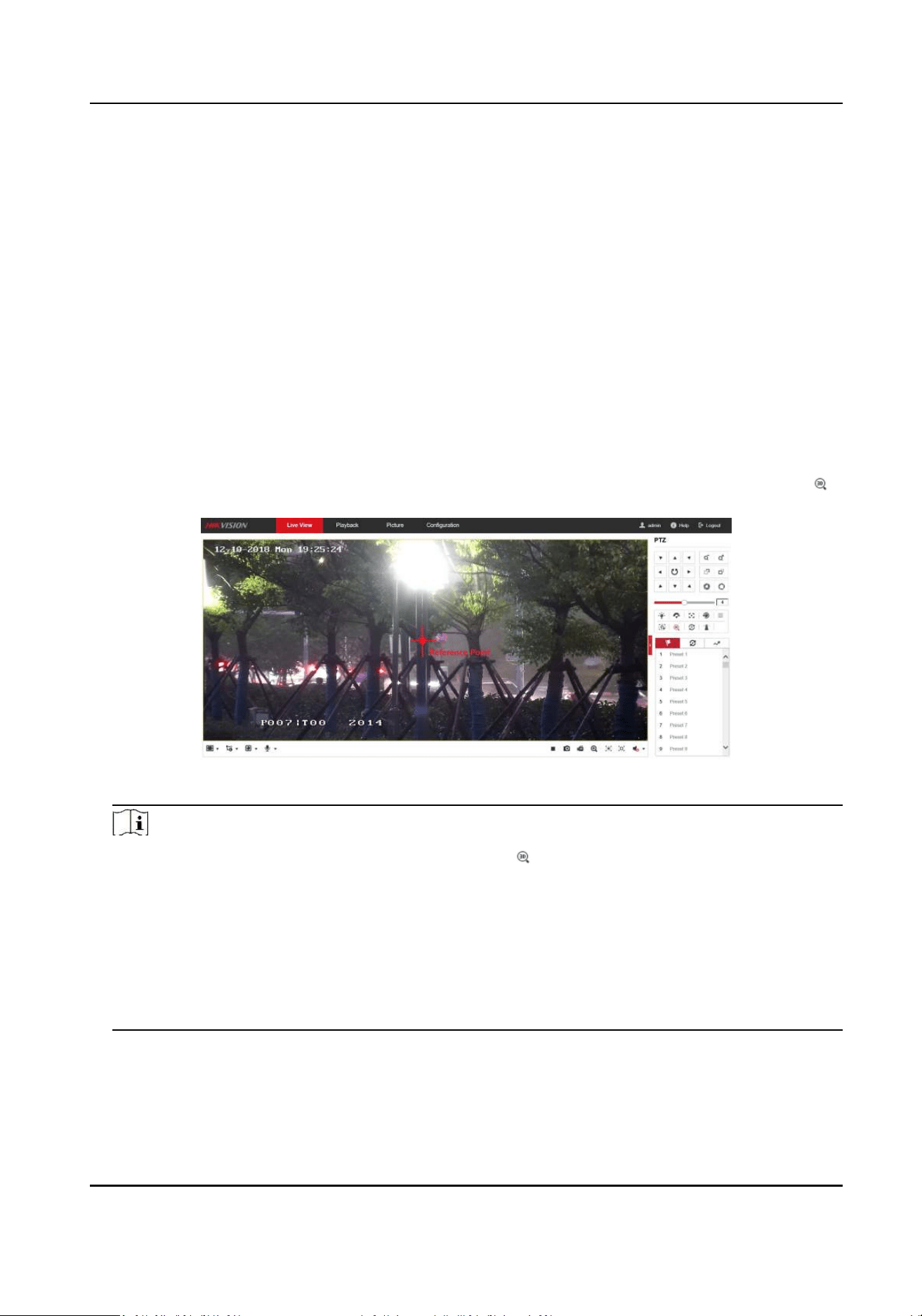
2. Enter the IP address of the speed dome in the web browser to enter the web client. Adjust the
PTZ buons to make sure that the reference point is displayed in the live view window. Click
to enable 3D locaon, click the reference point and the point will be in the middle of the frame.
Figure 5-1 Reference Point Posion
Note
• If the speed dome is installed lted, aer you click , you may nd the reference point is
above the center of the frame or it is outside the frame. In this case, you should adjust the
maximum elevaon angle of the speed dome. For detail adjustment method, please refer to
How to Solve the Problem that No Reference Point is on the Frame While Seng the Speed
Dome Inial Posion?
• if the maximum elevaon angle of the speed dome is adjusted, the reference point needs to
be adjusted to the center of the frame again.
• PTZ: Pan /lt /zoom.
3. Enter the Conguraon → PTZ → Inial Posion page, and click Set to set the inial posion.
Security Radar User Manual
15
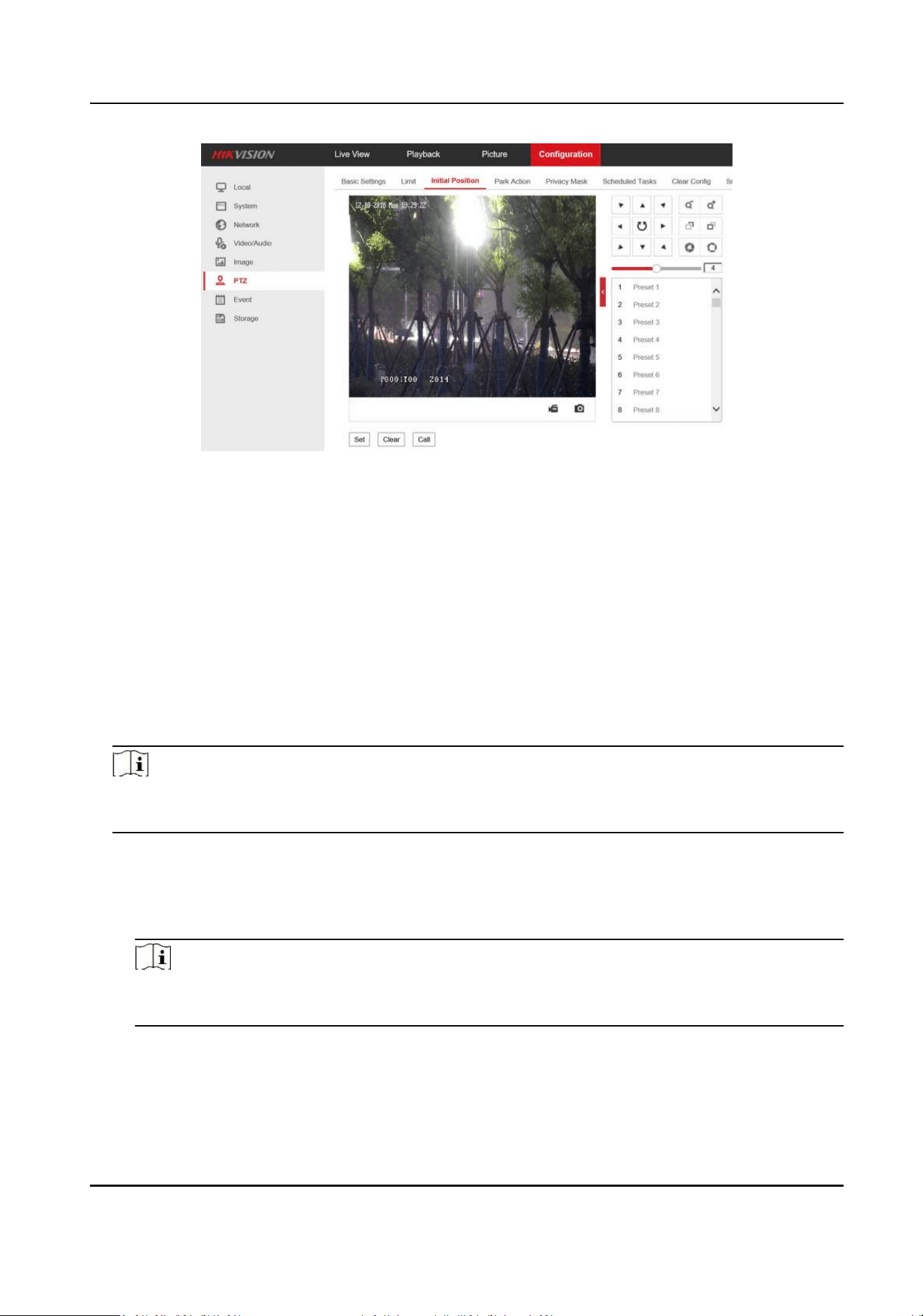
Figure 5-2 Set Inial Posion
5.2 Link the Camera to the radar
Before You Start
You need to disarm the radar before the operaon. Right-click on the radar detecon area, and
click Disarm to disarm the radar.
Steps
1. In the client soware, click Control Panel → Device Management . Select a radar in the device
list. Click Remote Conguraon → Smart Rule Sengs → Camera Linkage Sengs to enter the
page.
Note
You can also input IP address of the radar in a browser to enter the web client. Click Smart Rule
Sengs → Camera Linkage Sengs to enter the page.
2. Add a camera.
1) Click +.
2) Enter the IP address, port, user name, password of the camera, and select whether to link to
NVR.
Note
To use the NVR for video storage, you can choose to link the NVR and congure the NVR
parameters.
Security Radar User Manual
16
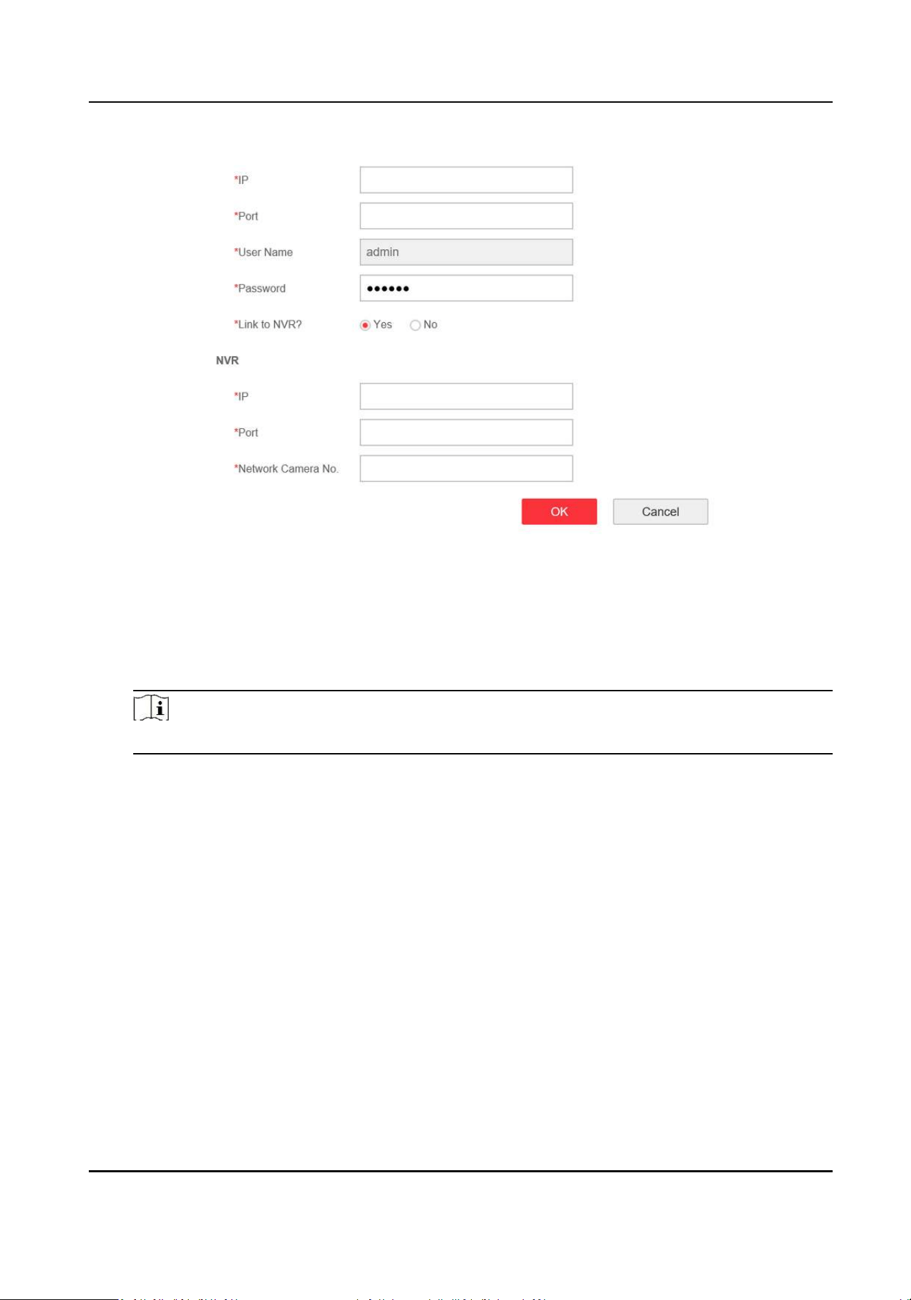
Figure 5-3 Add a Camera
3) Click OK.
3. Link zones and trigger lines to the camera.
1) Select a camera in the camera list.
2) Select zones and trigger lines in the Linkage Sengs.
3) Click Save.
Note
Up to 4 linked cameras can be enabled simultaneously on a single radar.
4. Add the camera to the client soware.
1) In the client soware, click Control Panel → Device Management .
2) Click Add in the device list, enter nickname, IP address, port, user name, password of the
camera. Check Export to Group.
3) Click Add.
5.3 Link the Camera to the Zone
Before You Start
• Add the zone to the radar.
• Add the camera to the client soware.
Steps
1. In the client soware, click Control Panel → Event Management → Zone Event to enter the
page/
2. Select a zone in the le list.
Security Radar User Manual
17
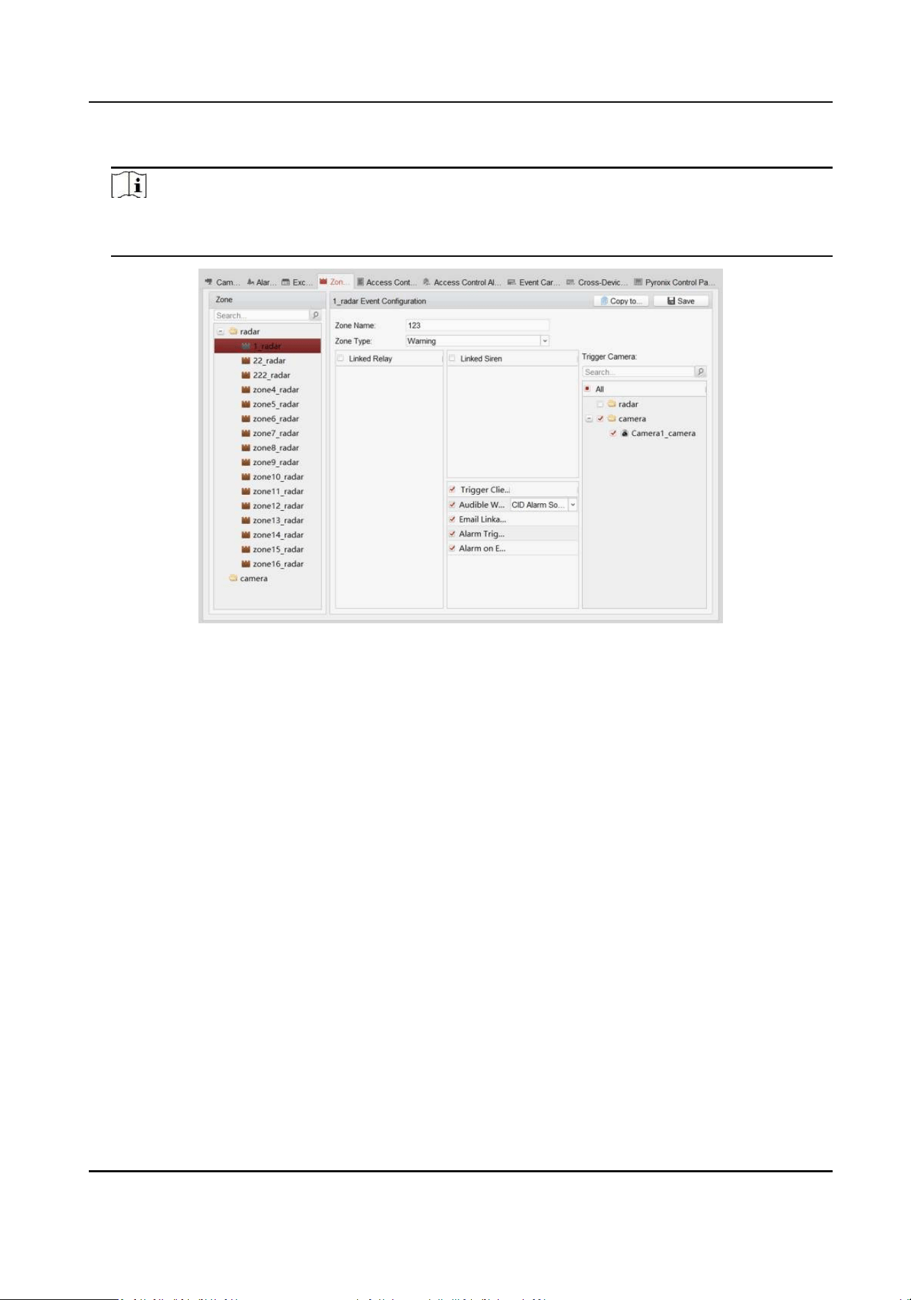
3. Select cameras to be linked in the Trigger Camera.
Note
• Each zone can link to 4 cameras, and up to 50 cameras can be linked.
• For more details, see User Manual of iVMS-4200 Client Soware.
Figure 5-4 Link the Camera to the Zone
4. Click Save.
5.4 Enable Alarm Triggered Pop-up Image
Before You Start
• Line the camera to the zone.
• Add the camera, the NVR and the radar to the client soware.
Steps
1. In the client soware, click Control Panel → Alarm Event to enter the page.
Security Radar User Manual
18
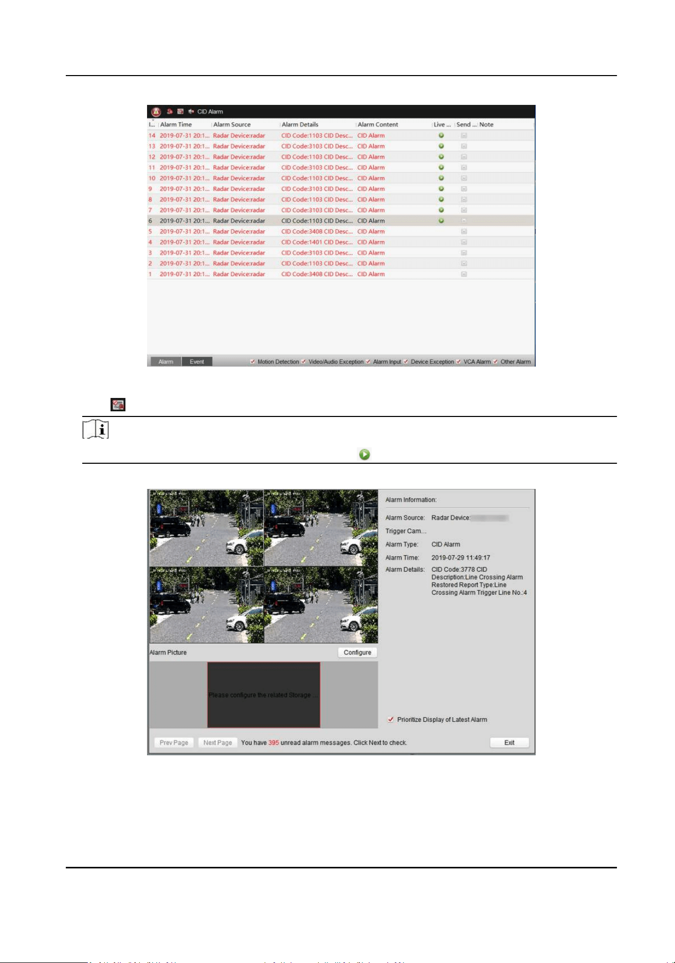
Figure 5-5 Alarm Event
2. Click to enable alarm triggered pop-up image.
Note
You can also double-click the alarm event or click to see details.
3. When the alarm is triggered, the client soware will automacally pop up an alarm window.
Figure 5-6 The Alarm Window
-
Right-click on the video window and select Capture. The captured image will be saved locally.
Security Radar User Manual
19
-
Check Priorize Display of Latest Alarm, the screen switches to 4-window mode and the
new alarm video will cyclically overlay 4 windows.
-
Click Prev Page or Next Page to view unread alarm messages.
-
Click Congure to enter Storage Schedule page. For detailed conguraon, see Set Storage
Schedule via Storage Server .
-
Click Exit to exit the alarm window.
4. Oponal: Click
to disable alarm triggered pop-up image.
Note
For more details, see User Manual of iVMS-4200 Client Soware.
5.5 Calibrate Camera
Calibrate the linked camera to ensure the accuracy of camera tracking.
Before You Start
• You need to disarm the radar before the operaon. Right-click on the radar detecon area and
click Disarm to disarm the radar.
• You need to link the speed dome to the zone before calibraon, and set the speed dome inial
posion.
• The installaon height of the linked speed dome should to be more than 3 m.
Steps
1. In the client soware, click Control Panel → Radar .
2. Click … → Master-slave Tracking Sengs on the upper-right corner of the page.
3. Double click the radar in the device list on the le. The live view window of the camera will be
displayed under the radar eld diagram.
Security Radar User Manual
20
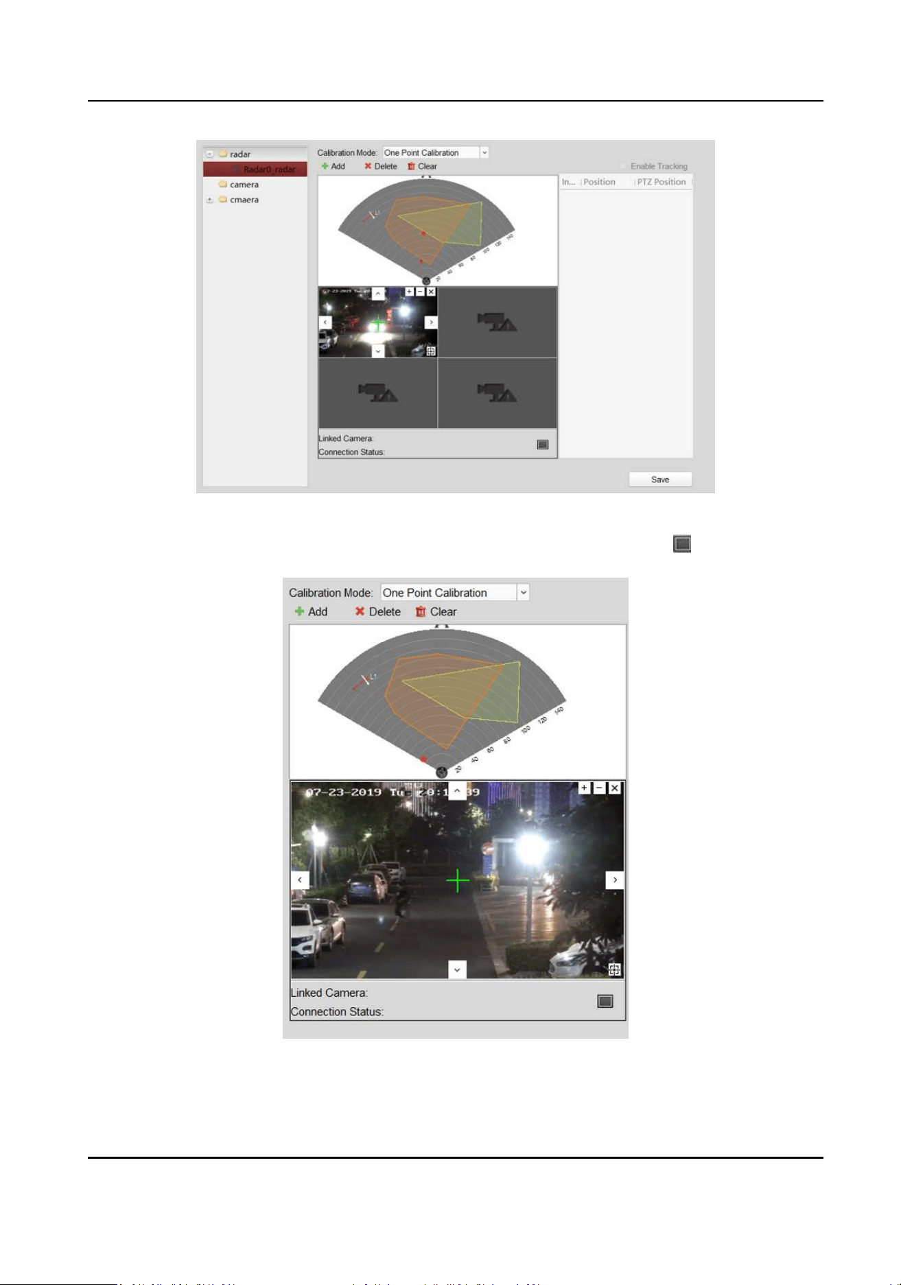
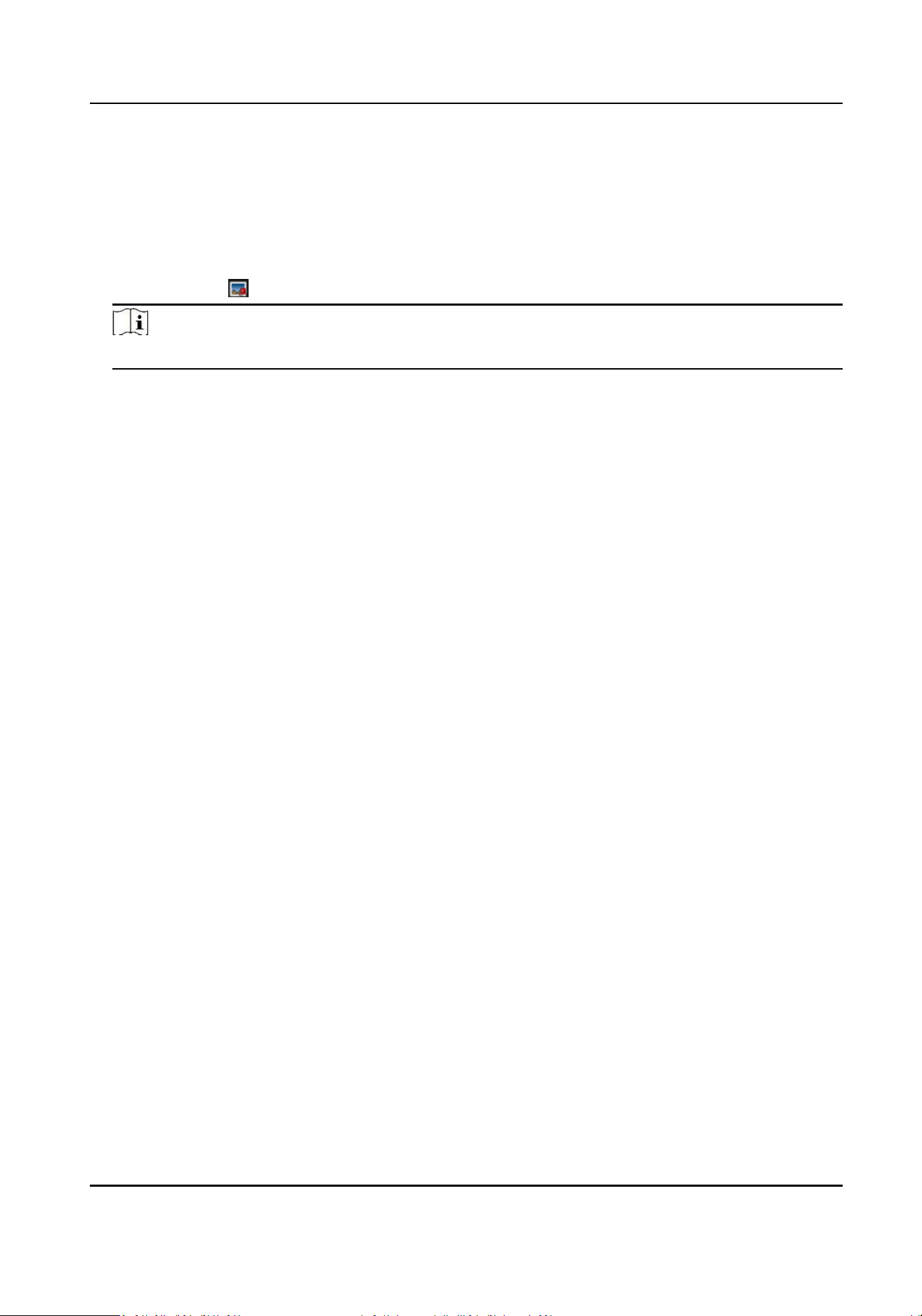
Figure 5-7 Calibraon Page
4. Select the live view window of the speed dome needs to be calibrated, click to maximum the
window.
Figure 5-8 Select the camera
5. Select a schedule for calibraon point selecon.
Security Radar User Manual
21
Note
According to the relave installaon posion of the radar and the speed dome, it is necessary to
select a schedule for the calibraon point selecon (One point calibraon or mulpoint
calibraon).
• One point calibraon: Applicable to the scene where the radar and the speed dome are
installed on the same pole or the speed dome is installed within a radar-centered range of 2
m (regardless of the altude dierence between the speed dome and the radar).
• Mulpoint calibraon: The scene where is not applicable to the one point calibraon need to
adopt the mulpoint calibraon method.
Security Radar User Manual
22
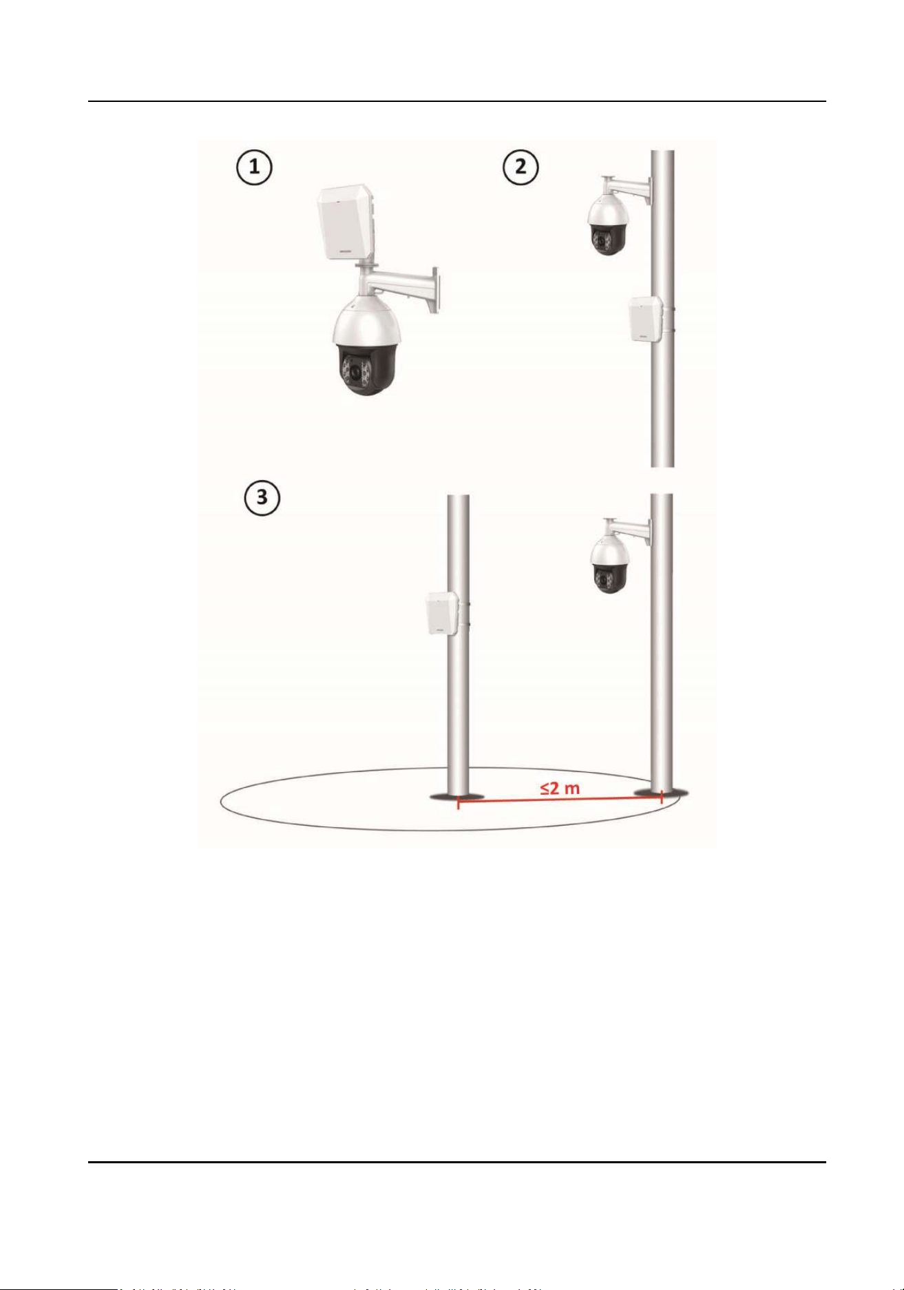
Figure 5-9 Installaon Scene for One Point Calibraon
Security Radar User Manual
23
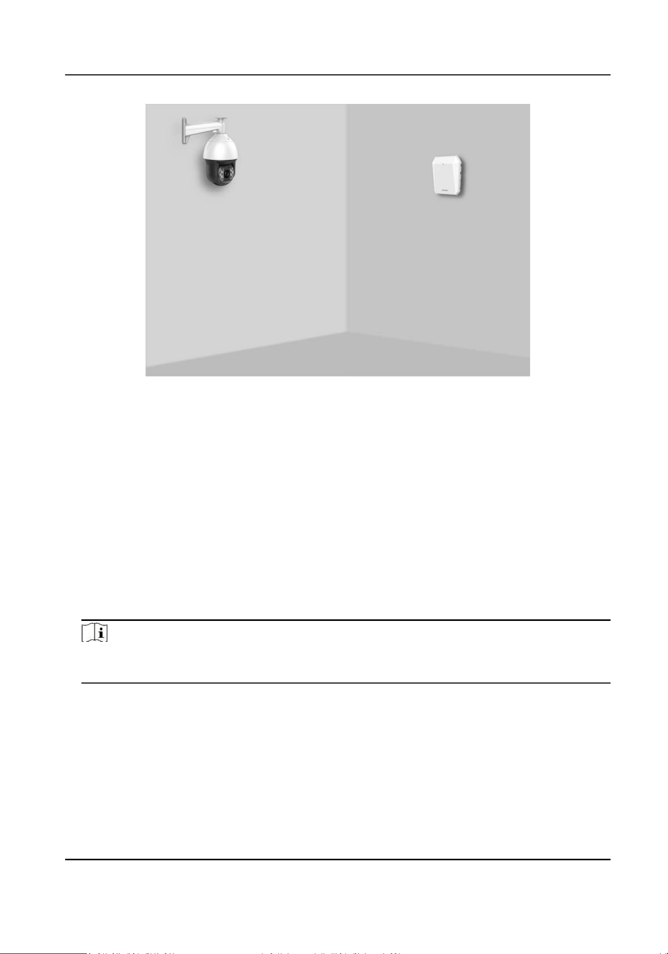
Figure 5-10 Installaon Scene for MulPoint Calibraon
6. Calibrate the camera. According to the selected schedule, calibrate the camera by one point
calibraon or mulpoint calibraon method.
5.5.1 One Point Calibraon
Before You Start
Arrange a sta (Operaon sta) to perform the calibraon operaon in the client soware, and a
sta (Calibraon sta) to cooperate with the calibraon.
Steps
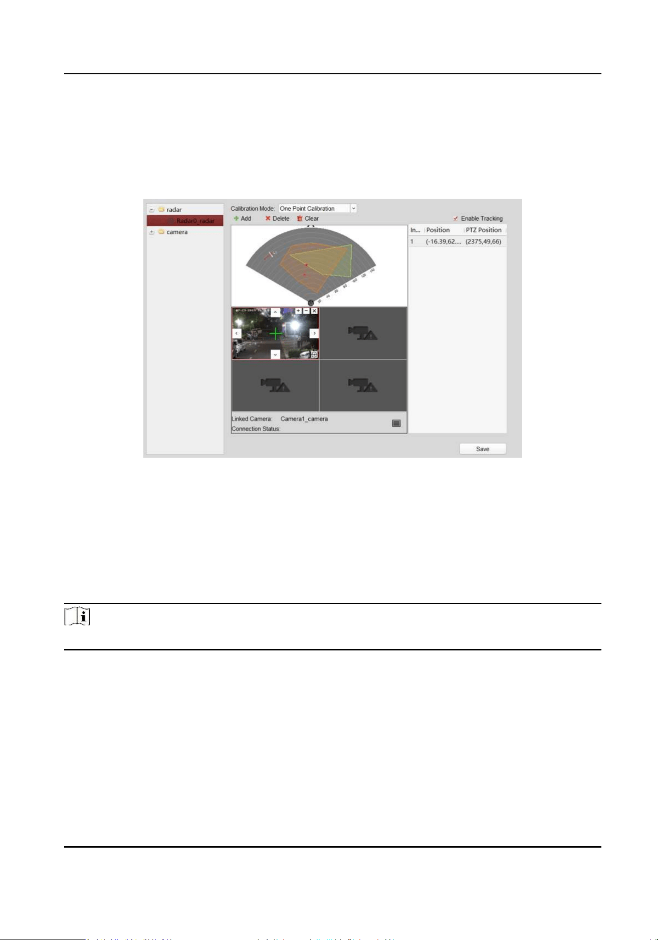
1. In calibraon page, select One Point Calibraon as the Calibraon Mode.
2. Click Add to add a calibraon point, the PTZ posion and the radar posion of the calibraon
sta will be shown in the list on the right.
Note
Click the calibraon point in the list on the right, you can click Delete to delete the calibraon
point.
3. Select the track of calibraon sta: Ask the calibraon sta to move into the radar detecon
eld. Compare the moving object in the live view window of speed dome and the track in the
radar eld diagram, the operaon sta needs to select the track of the calibraon sta and click
it. The color of the selected track will change from red to white.
Security Radar User Manual
24
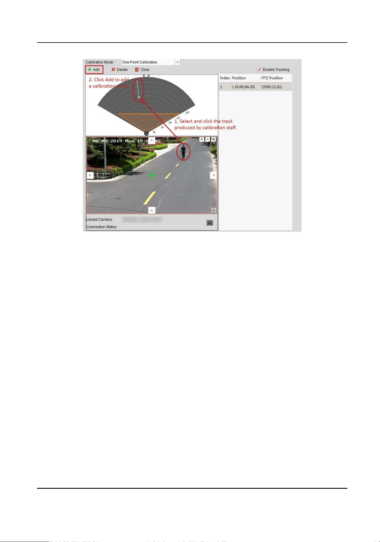
Figure 5-11 Add a Calibraon Point and Select the Track
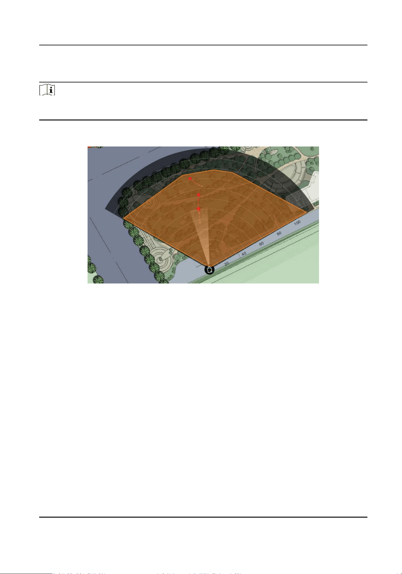
4. Get the radar posion and the PTZ posion of the calibraon sta at the calibraon point.
1) Ask the calibraon sta to move to the calibraon point within 20 to 40 m directly in front of
the radar, and then stand at the calibraon point.
2) When the calibraon sta keeps standing at the calibraon point, the operaon sta clicks
the calibraon point in the list on the right to get the radar posion of the calibraon sta.
Security Radar User Manual
25
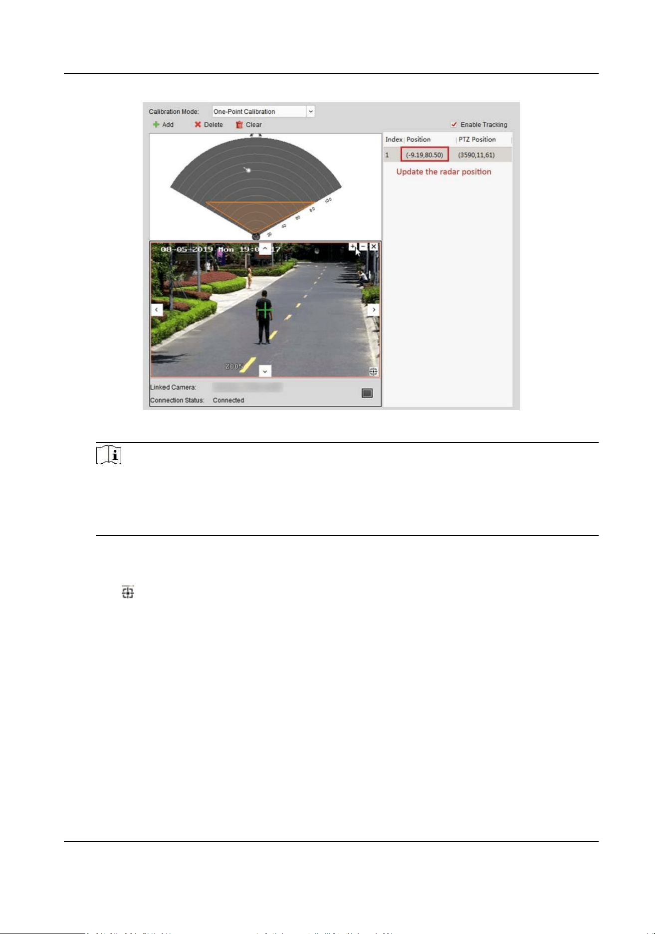
Figure 5-12 Get the Radar Posion
Note
The track disappears if the calibraon sta is standing in the place for more than 7s. If the
calibraon sta does not move to the calibraon point when the track disappears, you need
to ask the calibraon sta to move again to produce a track, and click the track to connue
the calibraon.
3) Adjust the PTZ buons in the live view window to get the PTZ posion: Click + and - to adjust
the altude of the calibraon sta to two-thirds of the altude of the window, and click the
direcon buons to align the central sign + with the calibraon sta (For precise alignment,
click to enable 3D locaon, and then click on the center of the object).
Security Radar User Manual
26
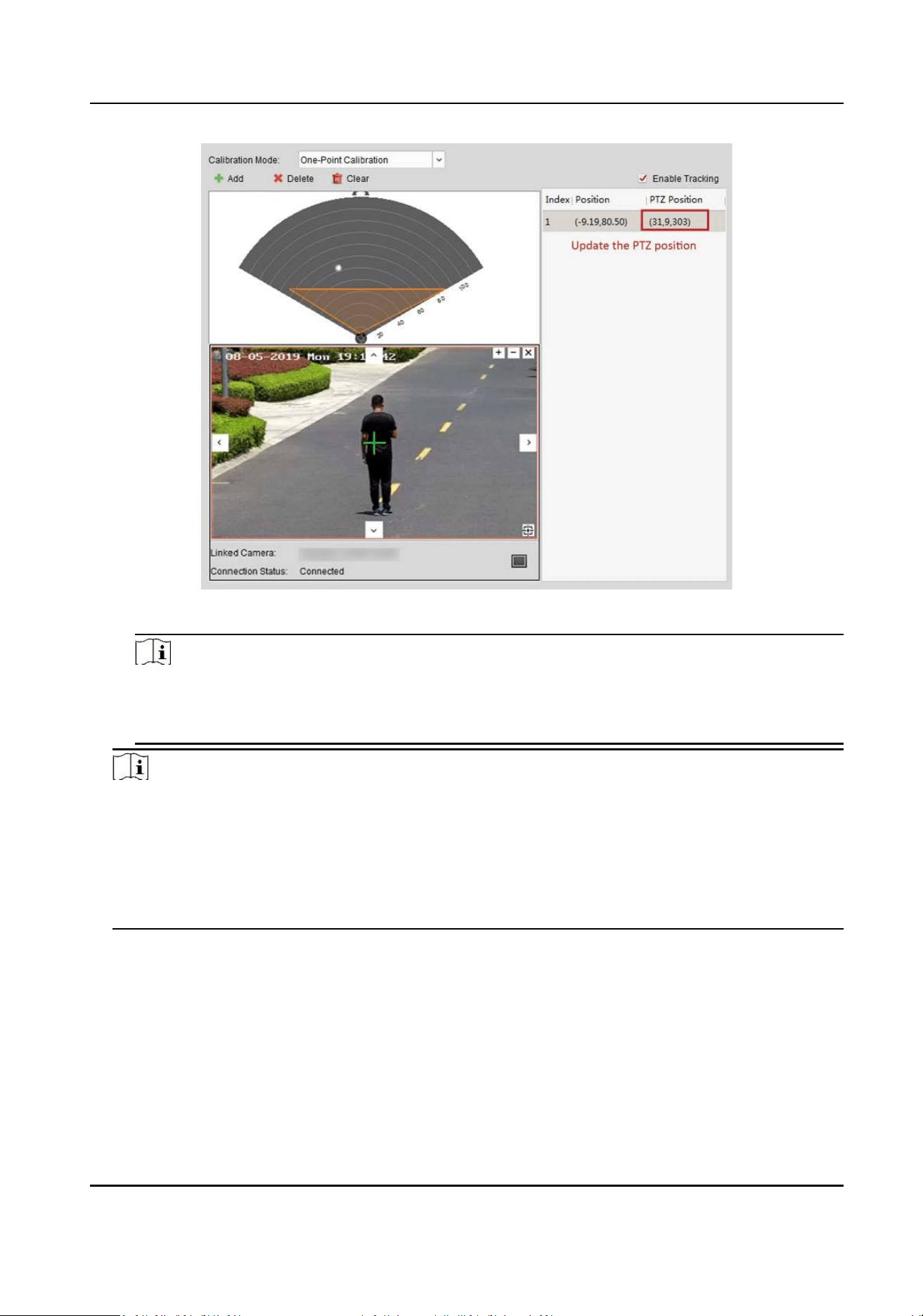
Figure 5-13 Get the PTZ posion
Note
When the PTZ posion updates, you need to compare the radar posion with the radar
posion updated in step b. If the radar posion of the two are inconsistent, go to step 4
again.
Note
• When calibrang, if the white track of the calibraon sta moves, click the calibraon point in
the list on the right, the radar posion will update; if you adjust the PTZ buons in the live
view window, the PTZ posion of the speed dome will update.
• Before the calibraon point is saved, the operaon sta is not allowed to adjust the PTZ
buons in the live view window (Adjustment will change the PTZ posion, and results in an
incorrect calibraon).
5. Click Save.
5.5.2 Mulpoint Calibraon
Before You Start
Arrange a sta (Operaon sta) to perform the calibraon operaon in the client soware, and a
sta (Calibraon sta) to cooperate with the calibraon.
Security Radar User Manual
27
Steps
1. In calibraon page, select Mulpoint Calibraon as the Calibraon Mode.
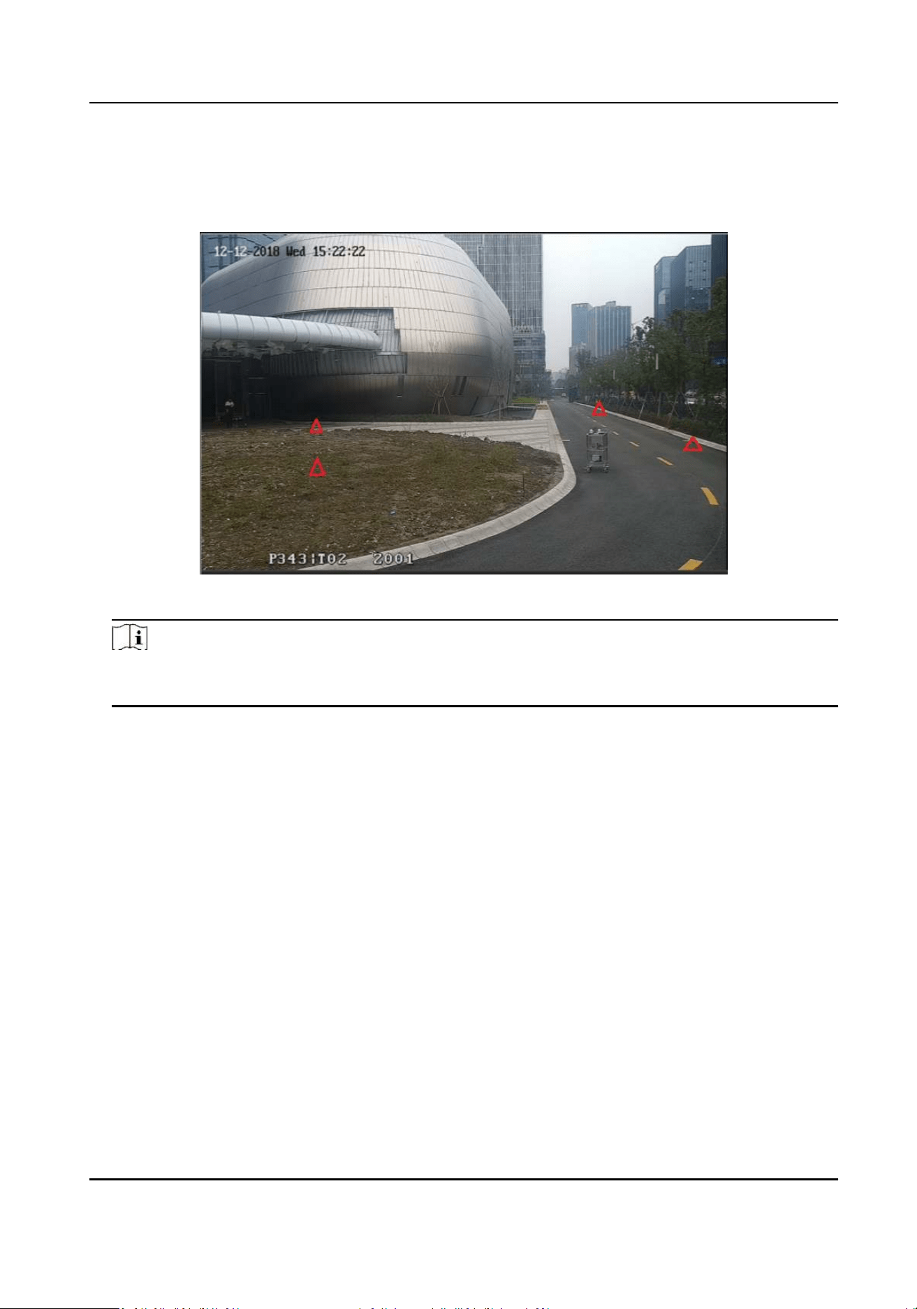
2. Select calibraon points (equally distributed) in the radar detecon eld, you can refer to the
following gure to select points.
Figure 5-14 Mulpoint Distribuon Instance
Note
It is required to set at least 4 calibraon points (equally distributed) when mulpoint
calibraon.
3. According to the calibraon points, ask the calibraon sta to move to a calibraon point, and
refer to step 2 to step 4 in One Point Calibraon to calibrate the calibraon point.
4. When the rst calibraon point is calibrated completely, let the calibraon sta move to the
next calibraon point aer the yellow track disappears. And then refer to step 2 to step 4 in One
Point Calibraon to calibrate the calibraon point. Follow this process to complete all calibraon
point posioning in turn.
Security Radar User Manual
28
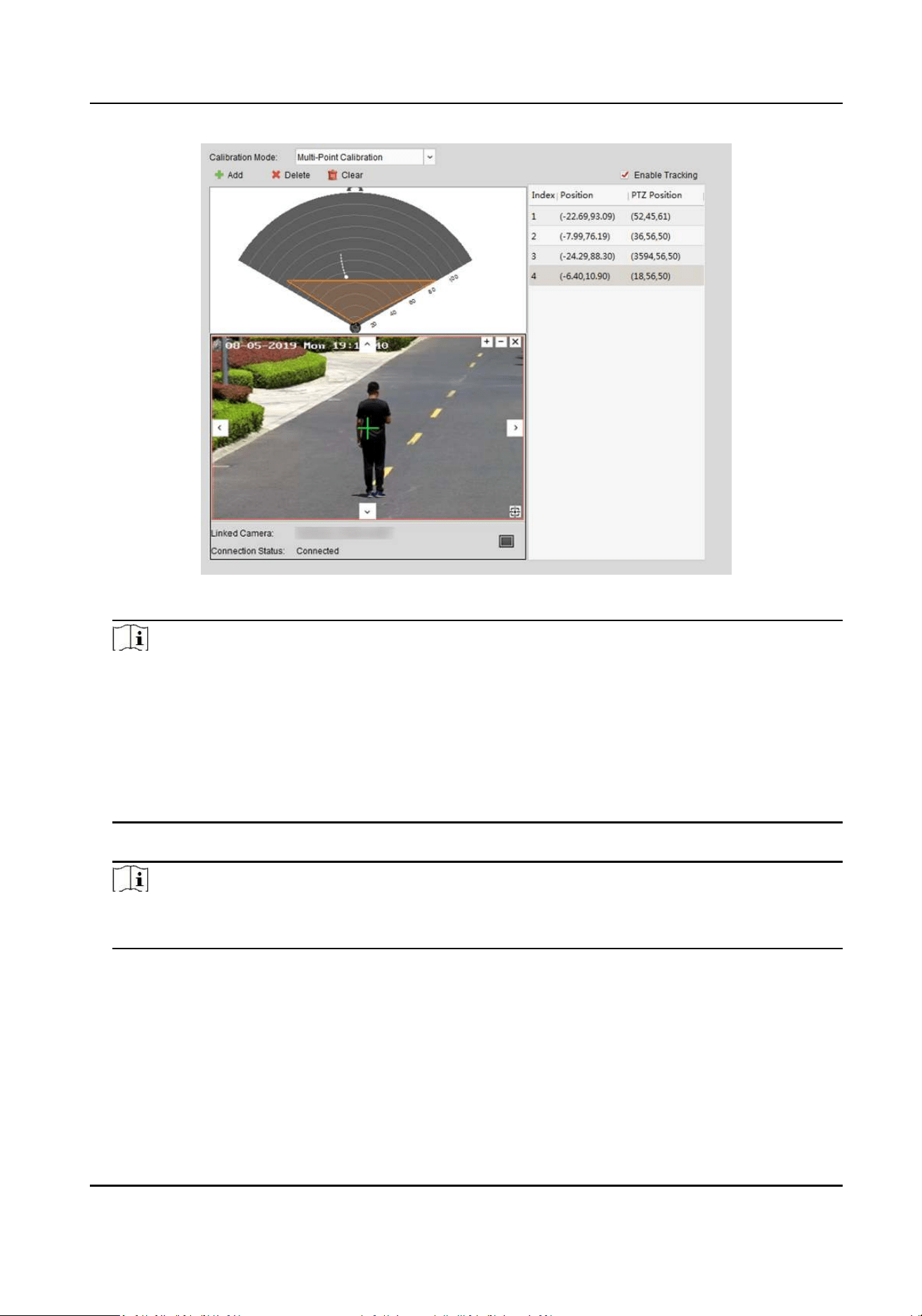
Figure 5-15 Mulpoint Calibraon
Note
• Every me a calibraon point is calibrated completely, the operaon sta should not adjust
the PTZ buons in the live view window (Adjustment will change the PTZ posion of the
current calibraon point, and results in an incorrect calibraon). You can adjust the PTZ
buons when calibrang the calibraon point.
• If you need to delete all calibraon points, click Clear; If you need to delete a calibraon
point, click the calibraon point in the list on the right, and then click Delete to delete the
calibraon point.
5. Aer all calibraon points is calibrated completely, click Save.
Note
You can save the calibraon informaon successfully if there are 4 or more calibraon points,
otherwise, you cannot save it.
5.6 Enable Camera Tracking
Enable the tracking funcon aer calibraon to make the linked camera be able to track with the
detected target.
Security Radar User Manual
29
Steps
1. In the client soware, click Control Panel → Radar → … → Master-Slave Tracking Sengs to
enter the page.
2. Expand the device group in the list on the le and double click the radar.
3. Select and click the live view window of the calibrated speed dome.
4. Check Enable Tracking, and click Save.
Figure 5-16 Enable Tracking
5.7 Set Park Funcon for Linked Camera
Aer enabling the radar park mode, the main radar will control the camera to return to the set
watch point, when no target appears within a period of me in the radar detecon area.
Before You Start
Note
Only analog cameras with watch point seng are supported.
• Add the radar to the map
• Link the camera to the radar, and add the camera to the client soware.
• Calibate the camera and enable camera tracking.
Steps
1. Enter Radar page in the client soware.
2. Right-click on the radar detecon are. Click Set Parking Point.
Security Radar User Manual
30
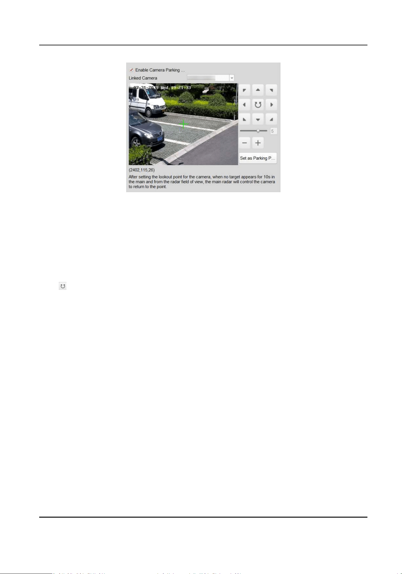
Figure 5-17 Set Camera Parking Point
3. Select a linked camera in the drop-down list.
4. Use funcon buons on the right to adjust the camera screen center posion (cross icon
posion) to the watch point.
Operaon Descripon
Direcon-control
Buon
Adjust the camera direcon. Hold to move the camera direcon
connuously.
Rotate the camera horizontally. Hold to connuously rotate the
camera horizontally.
Bar Adjust the rotaon speed of the camera. 1 is the slowest and 7 is the
fastest.
+/- Zoom the screen.
5. Click Set as Parking Point.
6. Check Enable Camera Parking Acon.
Security Radar User Manual
31
Chapter 6 Set Record and Storage Sengs
6.1 Set Storage Sengs
You can use storage server or NVR to store videos.
6.1.1 Set Storage Schedule via Storage Server
Before You Start
• Make sure your computer has already installed the Storage Server that should be selected as the
component when installing client.
• Acvate and add the storage server to the client before seng storage schedule, you can refer
to User Manual of iVMS-4200 Client Soware.
Steps
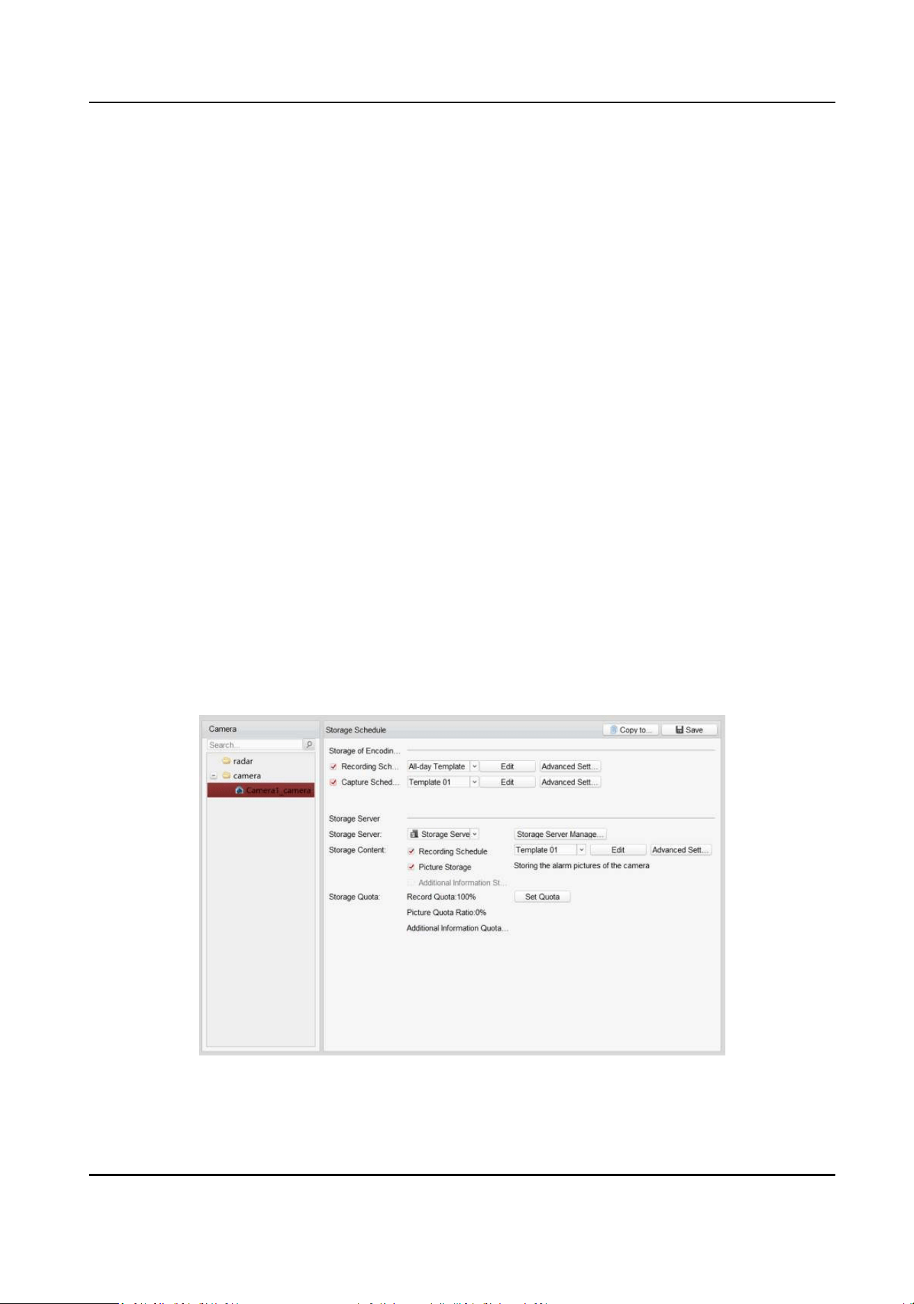
1. In client soware, click Tool → Storage Schedule to enter the page.
2. Select the camera in the Camera Group list.
3. Select a storage server from the Storage Server drop-down list.
4. Check Recording Schedule and Picture Storage in Storage Server module, and set templates.
5. Set quota.
1) Click Set Quota.
2) In the pop-up window, click Storage → General .
3) Set Quota Rao For Record, Quota Rao For Picture Quota Rao For Addional Info.
4) Click Save.
Figure 6-1 Storage Schedule
6. Check Recording Schedule and Capture Schedule in Storage of Encoding Server module.
Security Radar User Manual
32
7. Select a template in the drop-down list (All-day Template, Weekday Template, Event Template,
etc.).
8. Click Edit and Advanced Sengs to set the template.
9. Click Save.
Note
For detailed sengs, please refer to User Manual of iVMS-4200 Client Soware.
6.1.2 Set Storage Schedule via NVR
Steps
1. In the client soware, click Remote Conguraon, or input the IP address of radar in brower to
enter the web client.
2. Click Smart Rule Sengs → Camera Linkage Sengs to enter the page.
3. Add NVR.
-
Add an NVR to an exisng camera.
Select an exisng camera and click edit icon. Choose Yes in Link to NVR?. Enter IP address,
port and network camera No. and click OK.
-
Add NVR when adding a camera.
Click +. Choose Yes in Link to NVR?. Enter IP address, port and network camera No. and click
OK
6.1.3 Set Tracking Strategy
Steps
1. Select the radar and click Remote Conguraon in client soware, or enter the radar IP address
in the address bar of the web browser. Click Smart Rule Sengs → Video Record Strategy
Sengs to enter the page.
2. Select Time Priority, Range Priority, or Mul-Target Auto Switch as the strategy. The camera
will record the intrusion ll the target leave warning zone.
Time Priority
Record the rst target that intrude the zone.
Range Priority
Record the target that has the shortest distance away from the radar.
Mul-Target Auto Switch
Switch the target automacally when there are mulple targets in the zone. You should set
Switch Interval.
3. Click Save.
Security Radar User Manual
33
Chapter 7 Alarm Sengs
7.1 Alarm Center
You can set the alarm center's parameters and all alarms will be sent to the congured alarm
center.
Steps
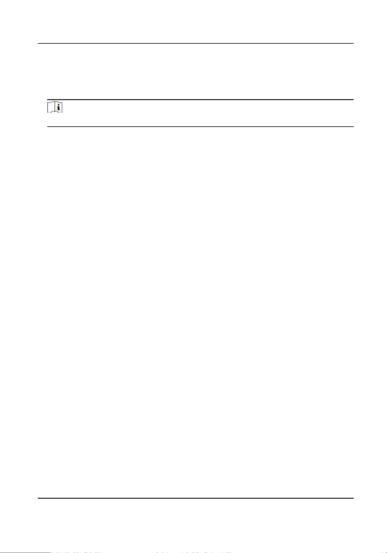
1. Click Communicaon Parameters → Alarm Center Parameters to enter the Alarm Center
Sengs page.
Figure 7-1 Alarm Center Parameters
2. Select Center Group, and slide the slider to enable the center group. The alarm informaon will
be uploaded to the selected center group.
3. Select Protocol Type from the drop-down list, select Server Address Type from the drop-down
list, enter the server address, port No., and the user name.
Note
The protocol type NAL2300 is the Hikvision private protocol.
4. Click Save.
7.2 Nocaon Push
When an alarm is triggered, if you want the send the alarm nocaon to the client, alarm center,
cloud or mobile client, you can set the nocaon push parameters.
Steps
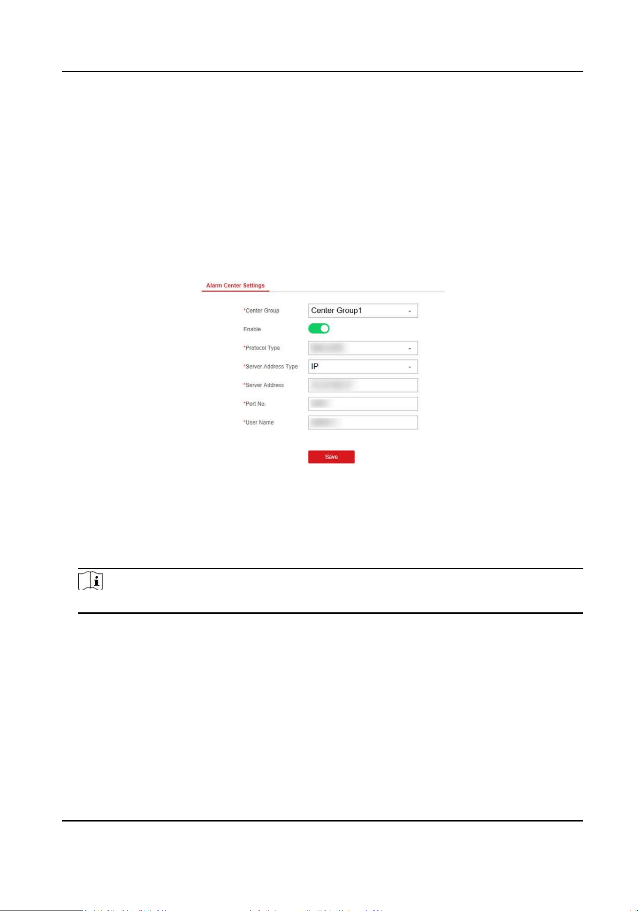
1. Click Communicaon Parameters → Message Nocaon .
Security Radar User Manual
34
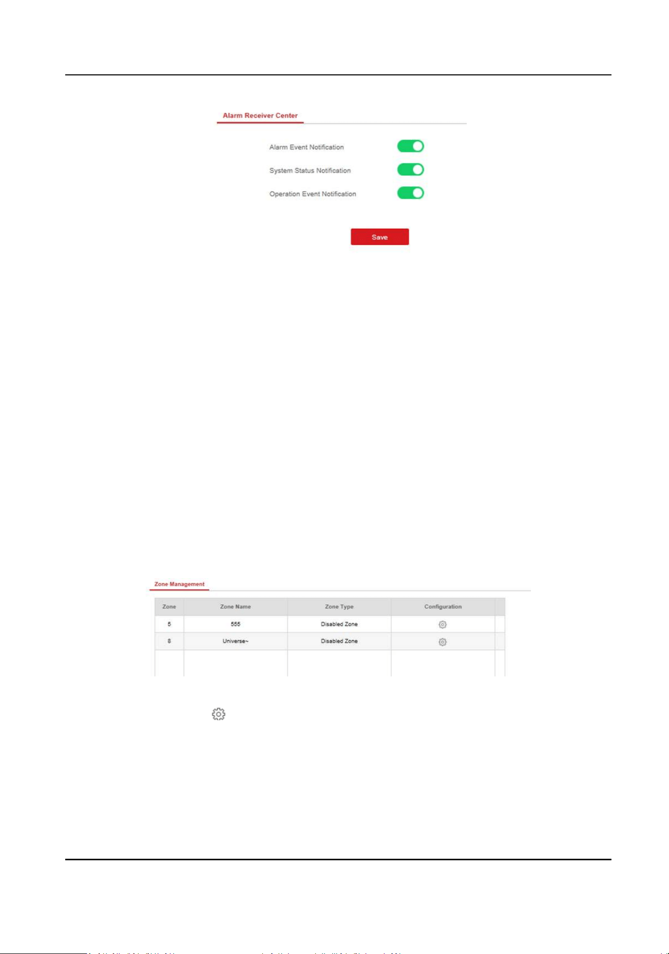
Figure 7-2 Nocaon Push
2. Enable the target nocaon.
Alarm Event Nocaon
The device will push nocaons when the zone alarm is triggered or restored.
System Status Nocaon
The device will push nocaons when any status in the system is changed.
Operaon Event Nocaon
The device will push nocaons when the user operate the device.
3. Click Save.
7.3 Set Zone
Steps
1. Select the radar and click Remote Conguraon in the client soware, or enter the radar IP
address in the address bar of the web browser. Click Alarm Module Parameters → Zone to
enter the page.
Figure 7-3 Set Zone
2. Select a zone, and click to edit the zone name and zone type.
3. Click OK to complete.
Security Radar User Manual
35
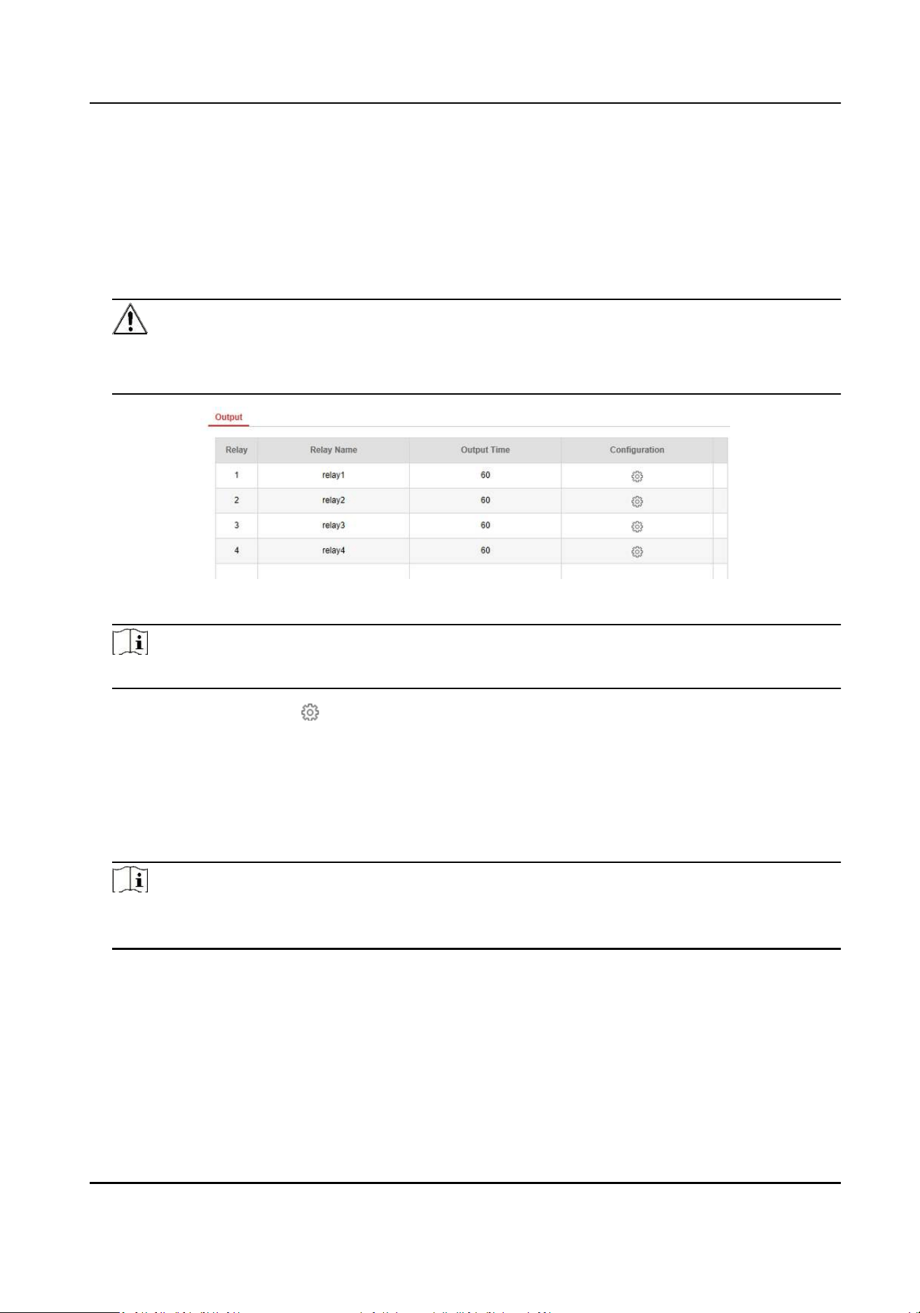
7.4 Set Alarm Output
Steps
1. Select the radar and click Remote Conguraon in the client soware, or enter the IP address
of the radar in the address bar of the web browser. Click Alarm Module Parameters → Relay to
enter the page.
Cauon
• 3-ch weak current alarm output: 0.5 A/125 VAC, breakdown voltage: 1 KV.
• 1-ch strong current alarm output: 10 A/240 VAC, breakdown voltage: 2.5 KV.
Figure 7-4 Relay
Note
You can also click Control Panel → Radar → → … → Alarm Output to open or close the relay.
2. Select an relay, and click to enter the page.
3. Edit the relay name, and output me.
4. Set relay linkage. Link the relay with alarm event, system event, and arming/disarming
operaon.
5. Oponal: Check Enable Zone Tracking. When enabled, aer the relay-linked zone is triggered by
an alarm, the relay will remain open unl the target exits the zone or the alarm is manually
closed.
Note
Aer the zone tracking is turned on, if only the zone is selected in the alarm event, the relay
output me is based on the me when the alarm triggered in the zone.
6. Click OK to save.
7. Click Delete to delete a selected period. Click Delete All to delete all periods in the me table.
Security Radar User Manual
36
7.5 Set Trigger Line
Steps
1. Select the radar and click Remote Conguraon in the client soware, or enter the IP address
of the radar in the address bar of the web browser. Click Alarm Module Parameters → Trigger
Line to enter the page.
2. Select an relay, and click to enter the page. You can edit the name of the trigger line.
3. Click OK.
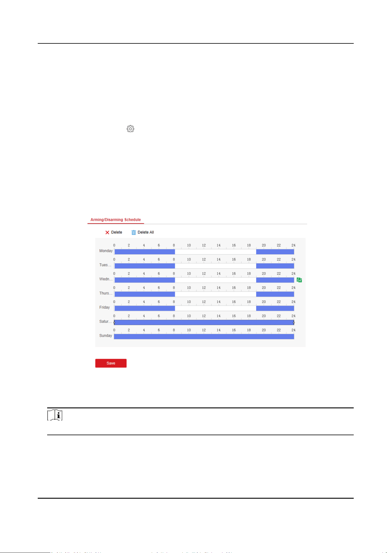
7.6 Set Arming/Disarming Schedule
Steps
1. Select the radar and click Remote Conguraon in the client soware, or enter the IP address
of the radar in the address bar of the web browser. Click Smart Rule Sengs → Arming/
Disarming Schedule to enter the page.
Figure 7-5 Arming/Disarming Schedule
2. Drag the mouse to draw the period bar on the me table, or click the period bar and enter the
start and end me.
Note
You can set 2 arming/disarming periods each day.
3. Click OK to save.
4. Click Delete to delete a selected period. Click Delete All to delete all periods in the me table.
5. Click Save.
Security Radar User Manual
37
7.7 Set Moon Speed
Steps
1. Select the radar and click Remote Conguraon in the client soware, or enter the IP address
of the radar in the address bar of the web browser. Click Smart Rule Sengs → Alarm Speed
Sengs to enter the page.
2. Check Moon Speed.
3. Slide the bar to set Min. Speed Threshold and Max. Speed Threshold.
Note
Aer enabled, only the target that move in set speed threshold will trigger the alarm.
4. Click Save.
7.8 Video Tracking Switch Sengs
Steps
1. Select the radar and click Remote Conguraon in the client soware, or enter the IP address of
the radar in the address bar of the web browser. Click Smart Rule Sengs → Video Tracking
Switch Sengs to enter the page.
2. Check Enable Mandatory Tracking.
3. Set me of mandatory tracking.
Note
Aer enabled, when you click a target track in the radar detecon area, the camera will
mandatory track the target.
4. Click Save.
Security Radar User Manual
38

Chapter 8 Set Radar Advanced Funcon
8.1 Set Master-slave Tracking Sengs
If the radar need mulple-radar linkage, you can arrange mulple radars for linkage detecon and
congure the radar master-slave relaonship.
Before You Start
There are at least 2 online radars.
Steps
1. Select the radar and click Remote Conguraon in the client soware, or enter the IP address of
the radar in the address bar of the web browser. Click Radar Sengs → Master-slave Tracking
Sengs to enter the page.
2. Set the radar type and parameters.
-
If the current radar is set as master radar, you can add, edit, delete the slave radar, and set
the slave radar priority.
-
If the current radar is set as slave radar, you need to set the main radar IP address.
What to do next
When the target is appear on the radar, the target informaon to be tracked is sent to the main
radar, and the main radar arranges linked cameras to track the target according to the set radar
priority.
8.2 Set Detecon Angle and Range
Steps
1. Select the radar and click Remote Conguraon in the client soware, or Enter the radar IP
address in the address bar of the web browser. Click Radar Sengs → Detecon Angle and
Range to enter the page.
Security Radar User Manual
39
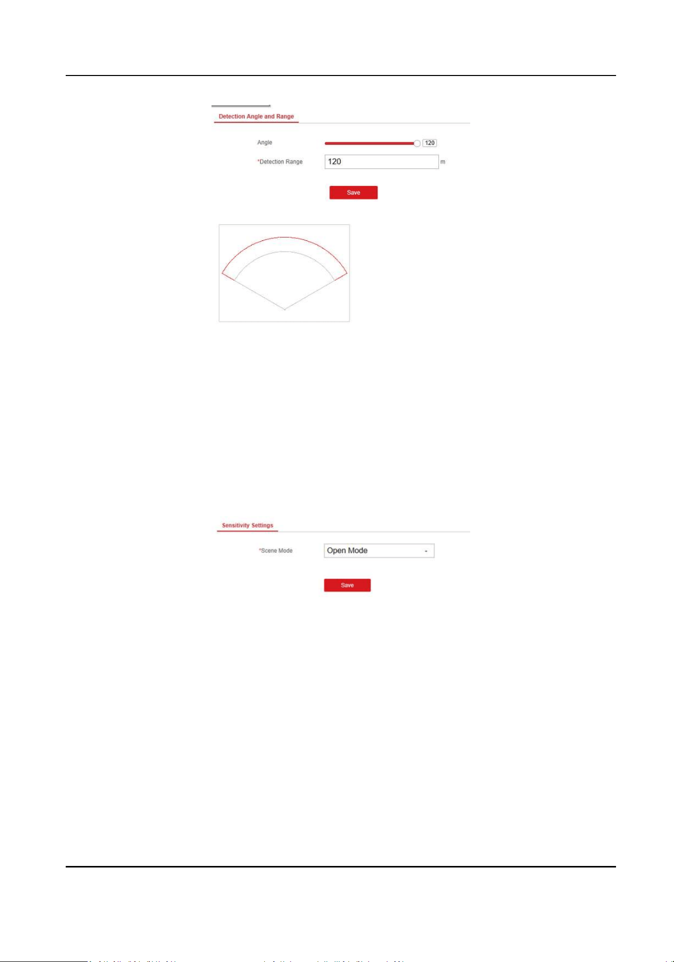
Figure 8-1 Set Detecon Angle and Range
2. Slide the bar to set the radar angle, and enter the detecon range.
3. Click Save to complete.
8.3 Set Scene Mode and Sensivity
Steps
1. Select the radar and click Remote Conguraon in the client soware, or Enter the radar IP
address in the address bar of the web browser. Click Radar Sengs → Sensivity Sengs to
enter the page.
Figure 8-2 Sensivity
2. Select Open Mode, Shrub Mode, or Expert Mode as the radar sensivity mode.
Open Mode
There are no large objects in the radar detecon area.
Shrub Mode
There are shrubs and other objects that are likely to swing in the radar detecon area. The
shrub mode can also used to decrease the interference of rainstorm.
Expert Mode (Custom Mode)
You can set tracking sensivity, swing sensivity, signal sensivity, speed sensivity and dwell
me according to actual scenario requirements.
Security Radar User Manual
40
Note
When adjusng the sensivity, the higher the value, the higher the detecon sensivity.
3. Click Save to complete.
8.4 Set Frequency Range Sengs
Steps
1. Select the radar and click Remote Conguraon in the client soware, or enter the IP address of
the radar in the address bar of the web browser. Click Radar Sengs → Frequency Range
Sengs to enter the page.
2. The radar supports 2 frequency bands, you can select one according to needs.
Note
• When mulple radars cover the same area, co-frequency interference can be reduced by
seng dierent frequency bands.
• Try to avoid overlapping radar detecon areas.
3. Click Save.
Security Radar User Manual
41
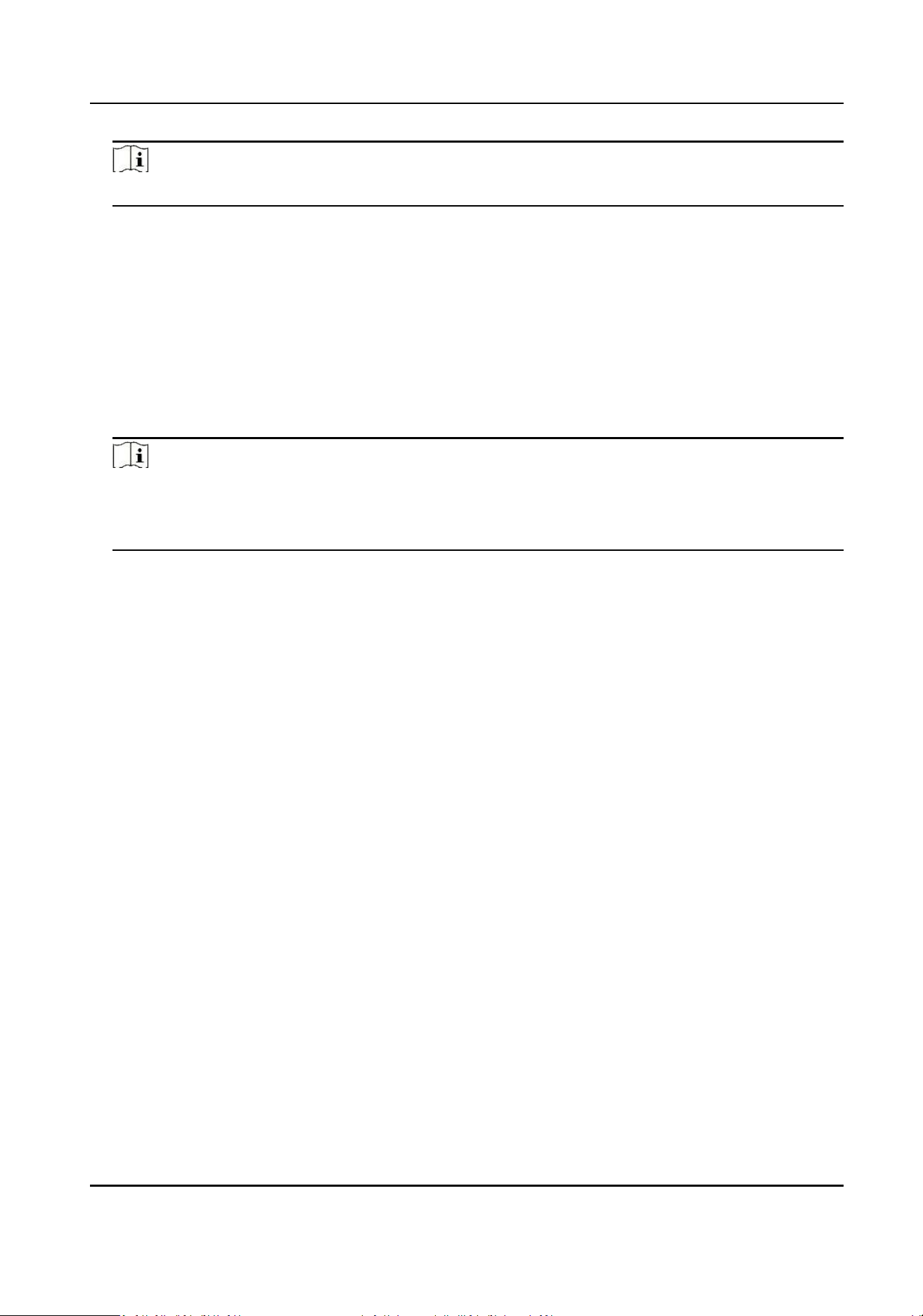
Chapter 9 View Alarm Informaon
The device supports alarm informaon query and alarm event playback.
Before You Start
Record and storage sengs are required before searching and playing back alarm events. For
details, see Set Record and Storage Sengs.
Steps
1. In the client soware, click Control Panel → Radar .
2. Select the radar that needs to view in the le list, and then click on the right side to open the
alarm informaon query page
3. Select the date, and then click Search.
4. Double-click an alarm event in the result list. The windows of radar track playback screen and
video playback of the selected alarm event will pop up.
Figure 9-1 Alarm event viewing and playback
Security Radar User Manual
42
Chapter 10 System Management
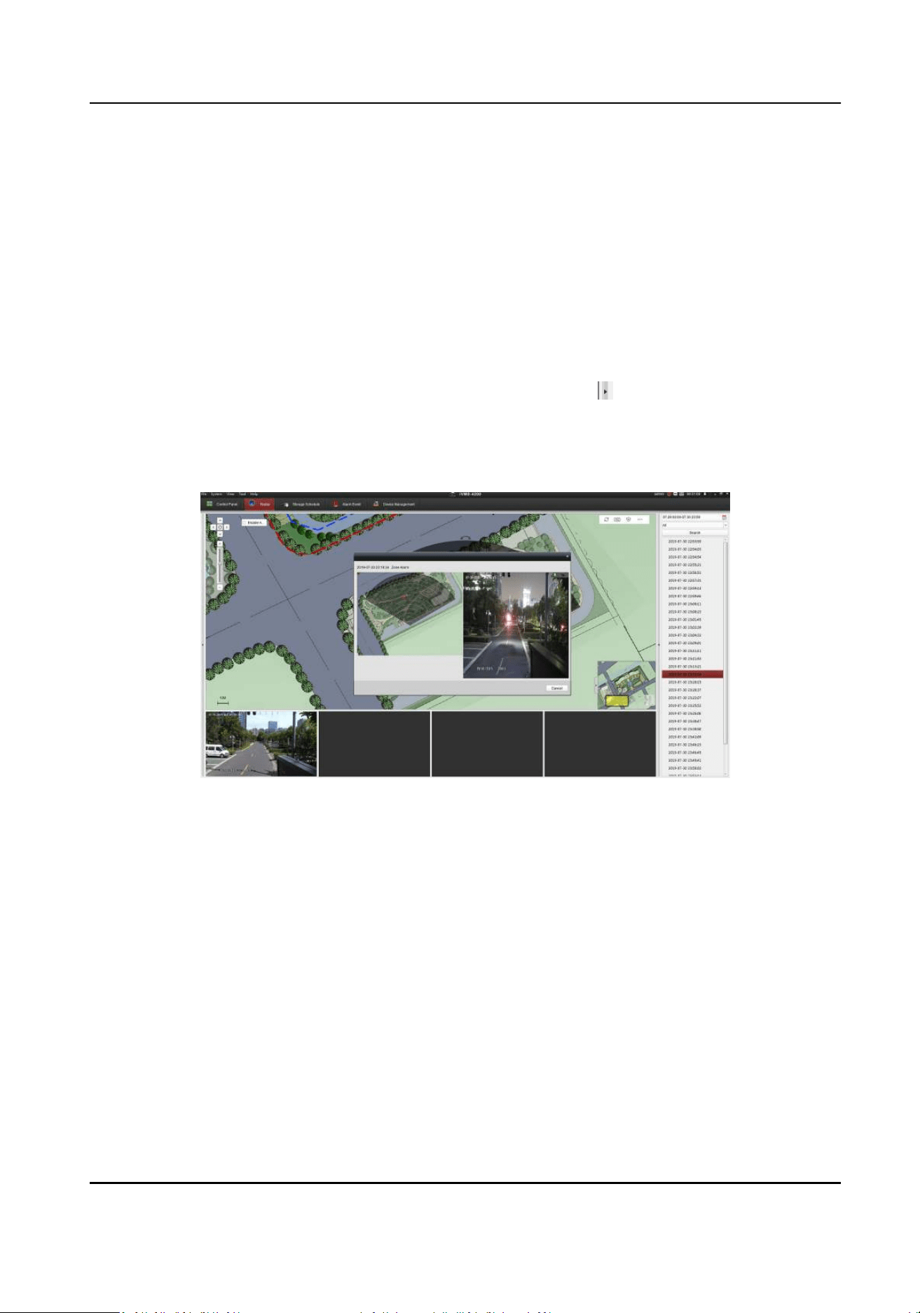
10.1 Set Time
Steps
1. Select the radar and click Remote Conguraon in the client soware, or enter the radar IP
address in the address bar of the web browser. Click System → Time to enter the page.
Figure 10-1 Time
2. Set the me zone and synchronizaon method.
3. Click Save.
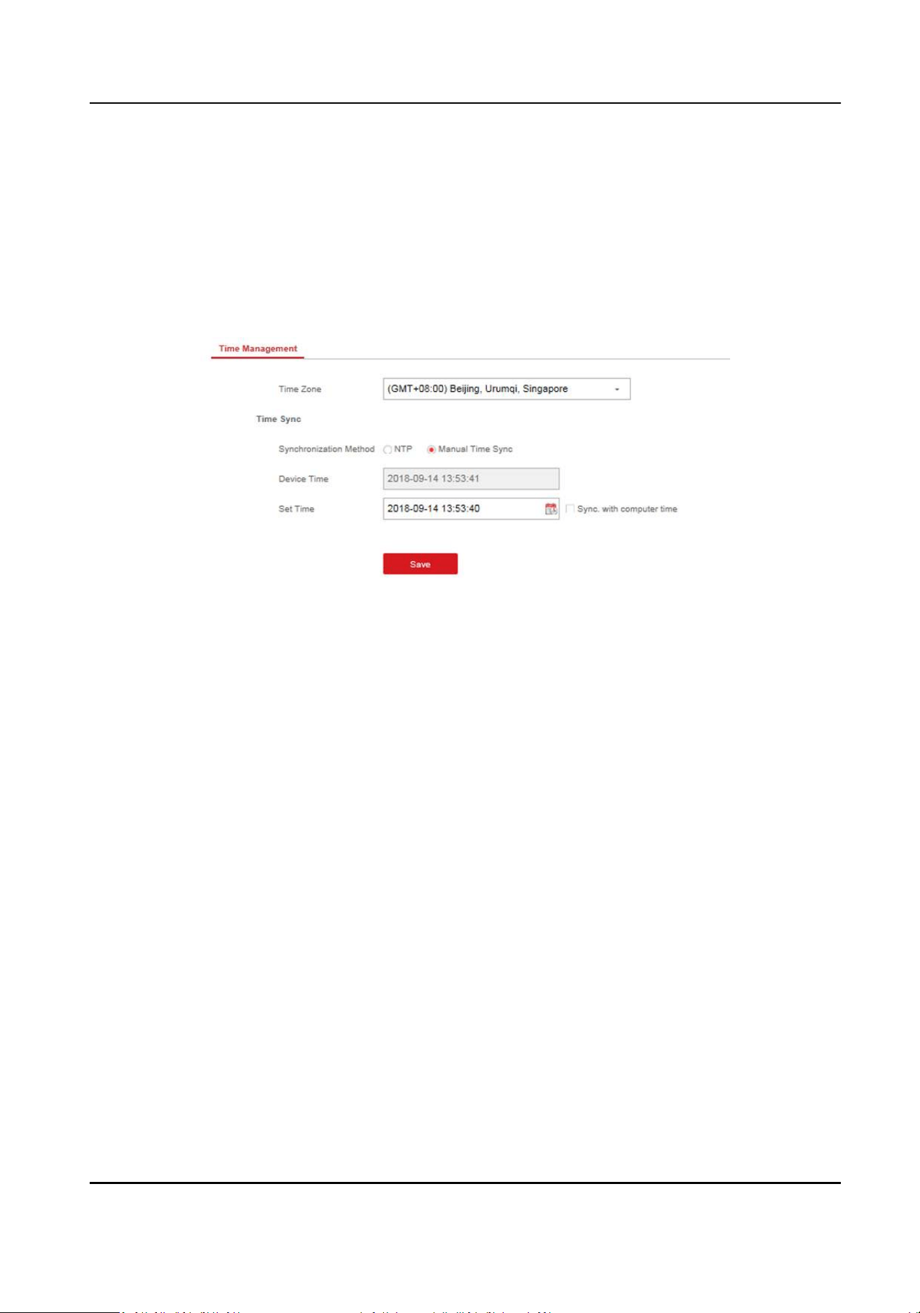
10.2 Manage User
Steps
1. Select the radar and click Remote Conguraon in the client soware, or enter the radar IP
address in the address bar of the web browser. Click System → User to enter the page.
Security Radar User Manual
43
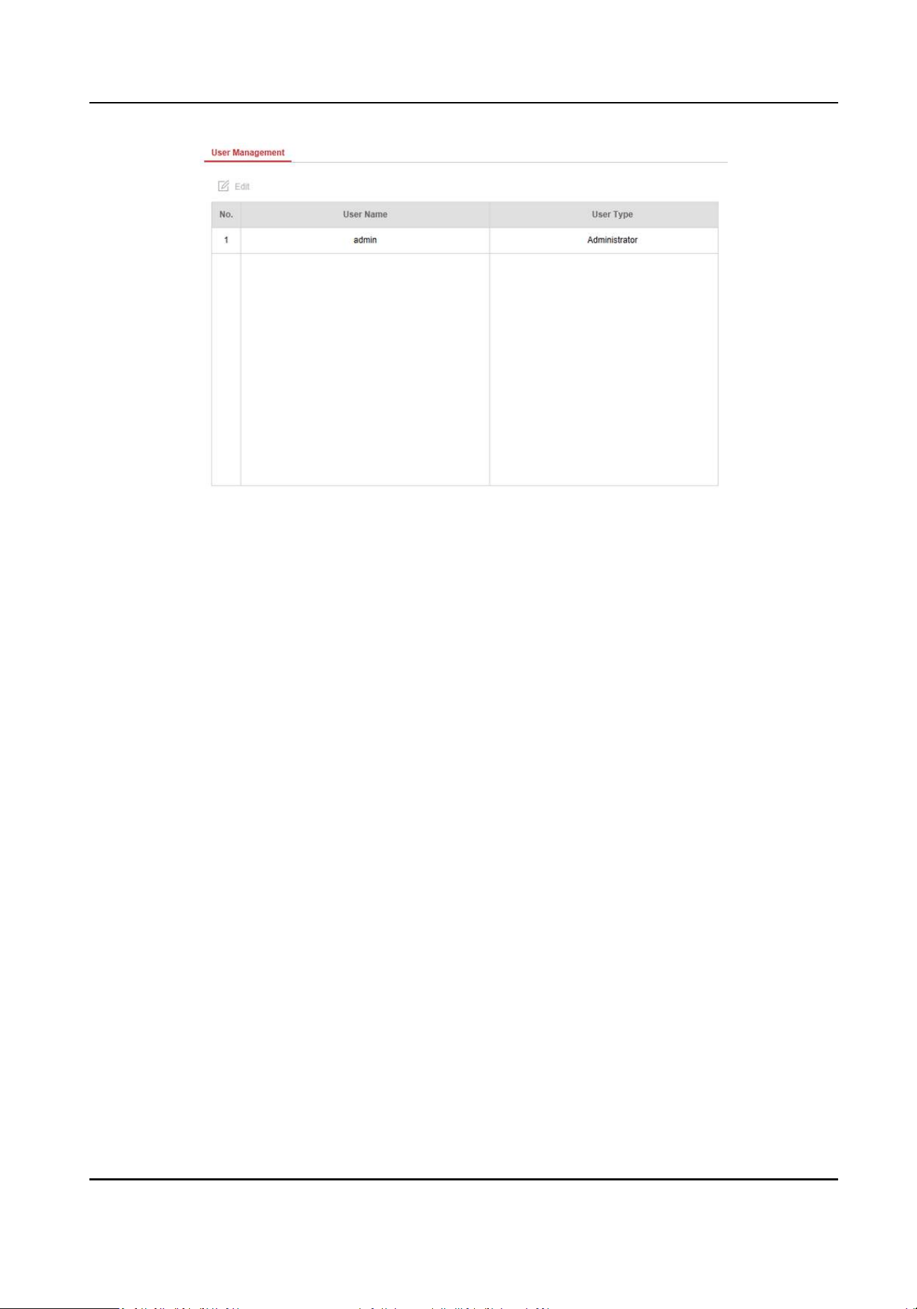
Figure 10-2 User
2. Select the admin account, and click Edit to edit the admin informaon.
10.3 System Maintenance
You can reboot the device, restore default sengs, import/export conguraon le, or upgrade
the device remotely.
Select the device and click Remote Conguraon in the client soware, or enter the device IP
address in the address bar of the web browser. Click System → System Maintenance to enter the
Upgrade and Maintenance page.
Reboot
Click Reboot to reboot the device.
Restore Default Sengs
Click Partly Restore to restore all parameters except for admin user informaon, wired network,
Wi-Fi network, detector informaon, and peripheral informaon to default ones.
Click Restore All to restore all parameters to the factory sengs.
Import Conguraon File
Click View to select conguraon le from the PC and click Import Conguraon File to import
conguraon parameters to the device.
Export Parameters
Click Export Conguraon File to export the device conguraon parameters to the PC.
Upgrade File
Security Radar User Manual
44
Click View to select an upgrade le from the PC and click Upgrade to upgrade the device
remotely.
Note
Do not power o when the device is upgrading.
10.4 View Device Informaon
Select the device and click Remote Conguraon in the client soware, or Enter the device IP
address in the address bar of the web browser. Click System Device → Device Informaon to enter
the page.
10.5 Search Log
Steps
1. Select the device and click Remote Conguraon in the client soware, or enter the device IP
address in the address bar of the web browser. Click System → Local Log Search to enter the
page.
2. Select Log type and me, and click Search to get the log list.
10.6 Enabling Remote Debugging
You are able to enable SSH (Secure Shell). When SSH is enabled, the technical support can log in to
the device remotely to view the prinng informaon of the device.
In the client soware, click System → Security to enter the SSH Sengs page and you can enable
or disable the SSH funcon.
Security Radar User Manual
45
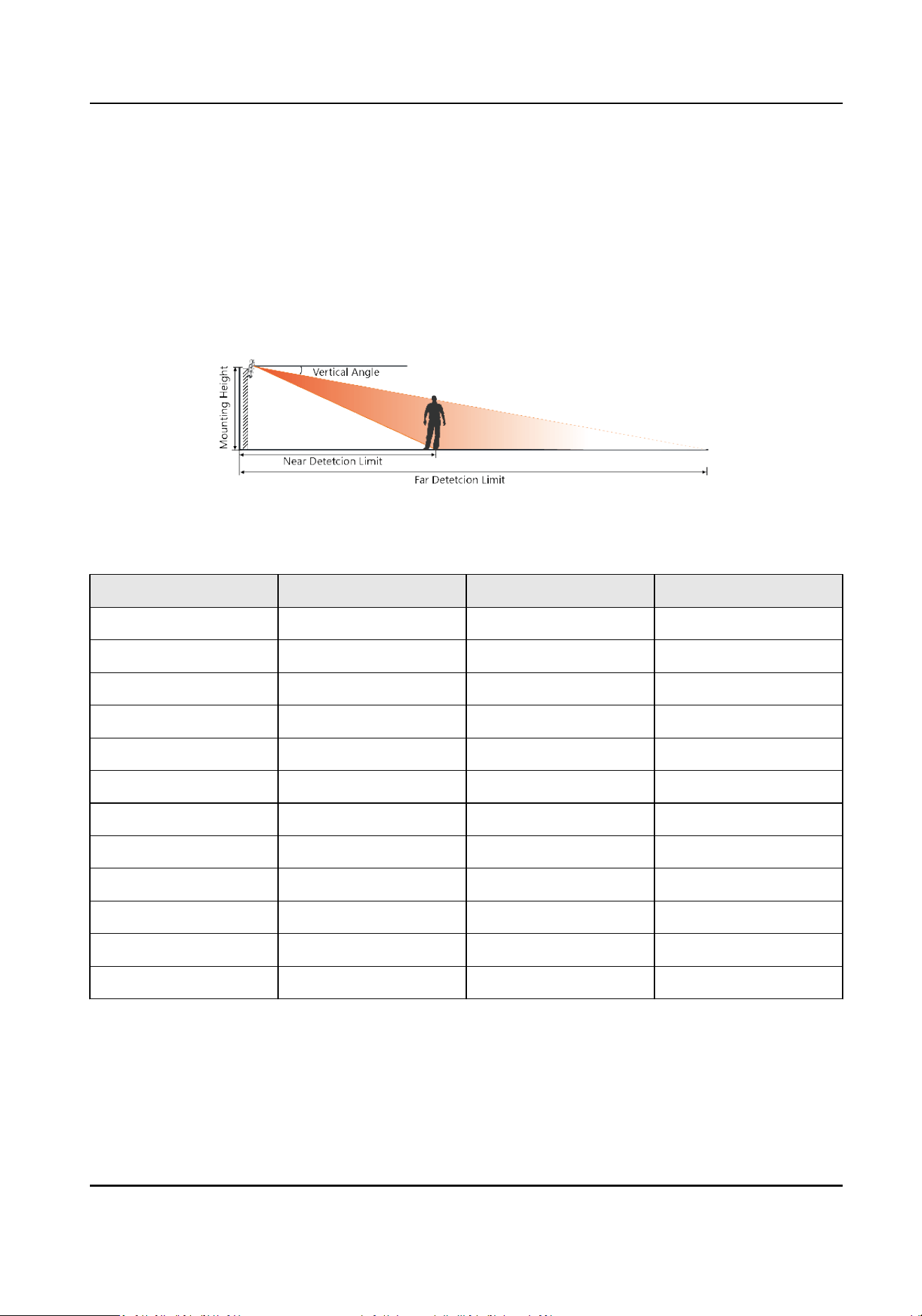
Appendix A. Radar Mounng Height
Recommendaon
The recommended installaon height is 2 to 3 m.
The following table shows the detecon range at dierent mounng heights.
Figure A-1 Radar Mounng Height and Detecon Range
Table A-1 Radar Mounng Height and Detecon Range
Mounng Height Vercal Angle Far Detcon Limit Near Detecon Limit
2.0 m 0° 102 m 4.2 m
2.0 m 3° 106 m 3.0 m
2.0 m 6° 87 m 2.4 m
2.0 m 9° 85 m 3.2 m
2.5 m 0° 124 m 5.5 m
2.5 m 3° 112 m 5.1 m
2.5 m 6° 89 m 4.2 m
2.5 m 9° 80 m 4.3 m
3.0 m 0° 119 m 7.8 m
3.0 m 3° 110 m 8.2 m
3.0 m 6° 98 m 7.1 m
3.0 m 9° 81 m 6.4 m
Security Radar User Manual
46

Appendix B. Formang Descripon
You can restore all parameters to default sengs for formang the security radar by the reset
buon.
You can format the device as follows.
Steps
1. Power o the radar, and then hold the reset buon while powering the radar on.
2. Keep holding unl the red and green LED ashes for 6 mes, then release the reset buon and
the radar will restart again.
3. All parameters will be restored to default values aer the radar restarts, and you need to
reacvate the radar.
Security Radar User Manual
47
Appendix C. Indicator Descripon
The indicator status descripon of the radar:
Table C-1 Indicator Descripon
Indicator Status
Solid Green Radar Powered on
Solid Red Zone Alarm Occurred
Flashing Red and Green Radar Network Disconnecon/Radar Sensor Excepon
When formang, the red and green LED ashes for 6 mes,
indicang that the formang was successful.
Security Radar User Manual
48
Appendix D. FAQ
D.1 How to Achieve an Opmum Detecon Range?
Answer:
You can refer to Radar Mounng Height Recommendaon for installaon of radar, and you should
test the radar aer installaon to make sure it is properly mounted. The test method is as follows:
Note
You need to enable OSD funcon before tesng.
The near detecon distance: arrange a tester to move directly from 20 m in front of the radar unl
the tester track disappear on the radar detecon area. The last tester distance that displayed by
OSD, is the near detecon distance.
The far detecon distance: Arrange a tester to move from the directly ahead of the radar and far
away from the radar installaon posion (outside the radar detecon area) to the radar detecon
area. When the target track rst appears in the detecon area, the tester stops moving. The last
tester distance that displayed by OSD, is the far detecon distance.
Note
When tesng the far detecon distance, the tester is required to move along the center normal of
the detecon area, to ensure opmum far detecon distance.
According to the tested near detecon distance and far detecon distance, and refer to Table A-1
Radar Mounng Height and Detecon Range to adjust the radar mounng angle.
D.2 How to Solve the Problem that the Radar is not Shown in the Device
List on the Radar Page?
Answer:
You should delete the radar and add it to the client soware again.
Note
The port number of the radar should be 80. When you add the radar to the client soware, set the
Port as 80.
D.3 How to Adjust the Sensivity to Avoid False Alarm?
Answer:
Security Radar User Manual
49
• If there are shrubs in the radar led, set the radar sensivity mode as Shrub Mode, which helps
avoid the false alarm caused by gale, storm, or shrub swing.
• If Shrub Mode is not saed, set the sensivity mode as Expert Mode (Custom Mode). Set the
Signal Sensivity less than or equal to two, the Swing Sensivity less than ve, and the Tracking
Sensivity less than or equal to ve.
D.4 How to Raise the Precision of Camera Tracking?
Answer:
• Check if the speed dome inial posion is set, if not, please set the speed dome inial posion.
• Check if the calibraon points are correct. Pay aenon to the situaon that the target is
intercepted when calibrang. If the calibraon points are error, please calibrate again.
• Check if the calibraon posions is equally distributed when you set the mul-point calibraon.
• Do not move the speed dome manually aer the calibraon. If the speed dome is manually
moved, please reset the inial posion of the speed dome and then calibrate again.
D.5 How to Solve the Problem that No Reference Point is on the Frame
While Seng the Speed Dome Inial Posion?
Answer:
If the speed dome is lted, it may cause that the reference point is above the center of the frame
or outside the frame while seng the speed dome inial posion. In this case, you should adjust
the maximum elevaon angle of the speed dome as follows.
Steps
1. Enter the IP address of the speed dome in the web browser to enter the web client.
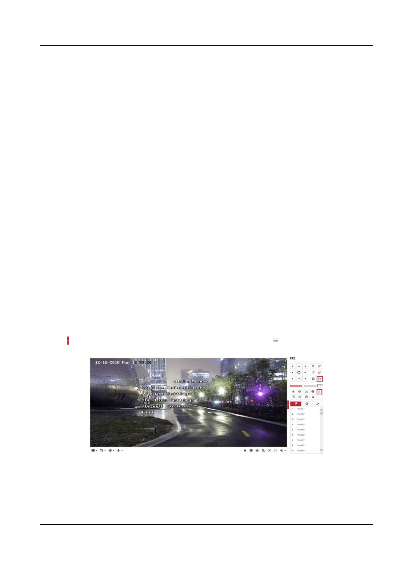
2. Click
to expand the PTZ list on the Live View page, and then click to enter the main menu of
the speed dome.
Figure D-1 The Main Menu of Speed Dome
Security Radar User Manual
50
Note
You can adjust the cursor for menu selecon by clicking the up and down direcon keys in the
PTZ list, and click to enter the selected item.
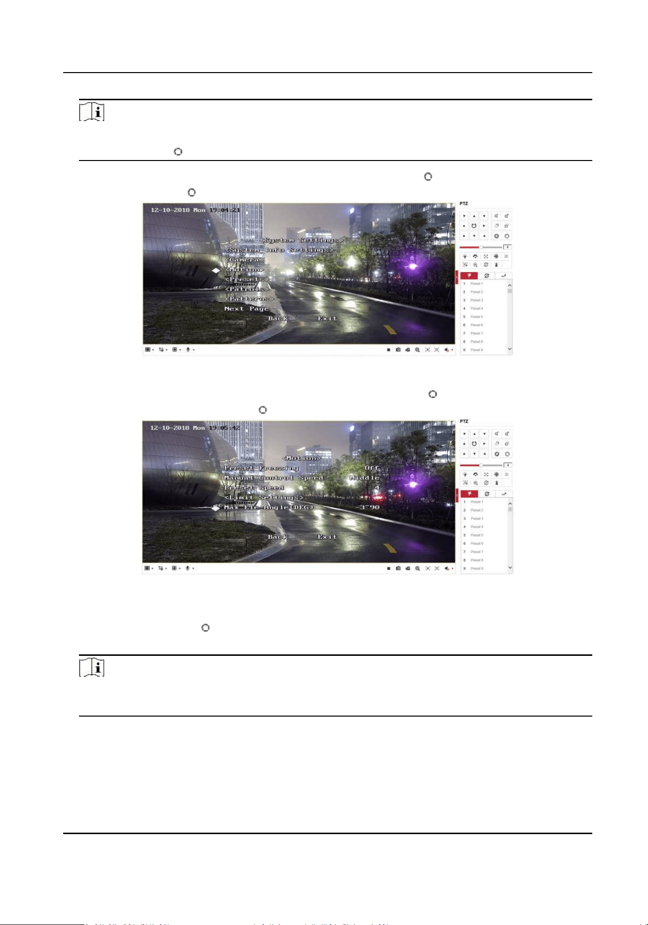
3. Adjust the cursor to System Sengs in the main menu and click . And then adjust the cursor
to Moon and click to enter the page.
Figure D-2 Moon
4. Adjust the cursor to Next Page in the sport mode menu and click . And then adjust the cursor
to Max Ele Angle (DEG) and click to enter the page.
Figure D-3 Maximum Elevaon Angle Adjustment
5. Click up and down direcon keys in the PTZ list to adjust the maximum elevaon angle, and
then you need to click to save the sengs.
6. Adjust the cursor to Exit to exit the menu.
Note
You need to reset the speed dome inial posion aer the maximum elevaon angle
adjustment.
Security Radar User Manual
51

D.6 What is the Reason that Failed to Draw a Zone Automacally?
Answer:
• The main reason is that the moving target (with track) does not form a closed-loop. You can
check if there is a clear intersecon of the track in the zone drawing page. If the track does not
closed, the drawn zone will be recognized as an invalid zone.
• When the object is moving for drawing a zone, if the track of the target is lost and then appear
again on the zone drawing page, and the distance between lost posion and the posion the
target appeared again is too far, the sengs will be failed.
D.7 What Makes a Failed Arming?
Answer:
The following two condions will make a failed arming:
• In the Radar page, if there is a moving target in the warning zone when you click → Arm to
arm radars, it is impossible to enable mandatory arming, resulng in failed arming.
• The current status of radar is oine.
D.8 Why Is It Required to Remove Reecve Objects from the Radar
Area?
Answer:
• When there are reecve objects in the radar applicaon scene, such as at glass or large-area
metal objects, the radar will produce mulpath eects, that is, the people reect the signal from
the radar to the large-area metal objects or at glasses, and the large-area metal objects or at
glasses reect the signal again to the receiving end of the radar, thus there will be a false alarm.
Since the glasses are at and the reecon is concentrated, there may be a false alarm when
there are glasses in the radar scene.
• The higher the sensivity, the more probability to trigger a false alarm.
D.9 Why Is the Camera Unable to Track the Target?
• The camera is not calibrated.
• The camera is not linked to the zone.
D.10 Common Mistakes of Calibrang Camera
Security Radar User Manual
52

Prompt when selecng target: Please select the calibraon target trajectory.
Reason: Target not selected or disappeared when acquiring parameters.
Soluon: Select the moving target for parameter acquision.
Prompt when adding calibraon points: Error in parameter range, illegal range: T <=0.
Reason: The angle of pitch, T, of the speed dome is less than or equal to 0.
Soluon: Adjust the angle of pitch of the speed dome so that T is greater than 0.
Prompt when adding calibraon points: Incorrect Parameters.
Reason: The status of the linked camera device is oine.
Soluon: Reconnect the camera. Make the status of the camera is online to connue calibraon.
Security Radar User Manual
53

UD15751B