Security Radar
User Manual
Legal Informaon
About this Document
●
This Document includes instrucons for using and managing the Product. Pictures, charts,
images and all other
informaon hereinaer are for descripon and explanaon only.
●
The
informaon contained in the Document is subject to change, without noce, due to
rmware updates or other reasons. Please nd the latest version of the Document at the
Hikvision website ( hps://www.hikvision.com ). Unless otherwise agreed, Hangzhou Hikvision
Digital Technology Co., Ltd. or its aliates (hereinaer referred to as "Hikvision") makes no
warranes, express or implied.
●
Please use the Document with the guidance and assistance of professionals trained in
supporng the Product.
About this Product
●
This product can only enjoy the aer-sales service support in the country or region where the
purchase is made.
●
If the product you choose is a video product, please scan the following QR code to obtain the
"Iniaves on the Use of Video Products", and read it carefully.
Acknowledgment of Intellectual Property Rights
●
Hikvision owns the copyrights and/or patents related to the technology embodied in the
Products described in this Document, which may include licenses obtained from third pares.
●
Any part of the Document, including text, pictures, graphics, etc., belongs to Hikvision. No part
of this Document may be excerpted, copied, translated, or modied in whole or in part by any
means without
wrien permission.
●
and other Hikvision’s trademarks and logos are the properes of Hikvision in
various
jurisdicons.
●
Other trademarks and logos menoned are the properes of their respecve owners.
LEGAL DISCLAIMER
●
TO THE MAXIMUM EXTENT PERMITTED BY APPLICABLE LAW, THIS DOCUMENT AND THE
PRODUCT DESCRIBED, WITH ITS HARDWARE, SOFTWARE AND FIRMWARE, ARE PROVIDED "AS
IS" AND "WITH ALL FAULTS AND ERRORS". HIKVISION MAKES NO WARRANTIES, EXPRESS OR
Security Radar User Manual
i

IMPLIED, INCLUDING WITHOUT LIMITATION, MERCHANTABILITY, SATISFACTORY QUALITY, OR
FITNESS FOR A PARTICULAR PURPOSE. THE USE OF THE PRODUCT BY YOU IS AT YOUR OWN RISK.
IN NO EVENT WILL HIKVISION BE LIABLE TO YOU FOR ANY SPECIAL, CONSEQUENTIAL,
INCIDENTAL, OR INDIRECT DAMAGES, INCLUDING, AMONG OTHERS, DAMAGES FOR LOSS OF
BUSINESS PROFITS, BUSINESS INTERRUPTION, OR LOSS OF DATA, CORRUPTION OF SYSTEMS, OR
LOSS OF DOCUMENTATION, WHETHER BASED ON BREACH OF CONTRACT, TORT (INCLUDING
NEGLIGENCE), PRODUCT LIABILITY, OR OTHERWISE, IN CONNECTION WITH THE USE OF THE
PRODUCT, EVEN IF HIKVISION HAS BEEN ADVISED OF THE POSSIBILITY OF SUCH DAMAGES OR
LOSS.
●
YOU ACKNOWLEDGE THAT THE NATURE OF THE INTERNET PROVIDES FOR INHERENT SECURITY
RISKS, AND HIKVISION SHALL NOT TAKE ANY RESPONSIBILITIES FOR ABNORMAL OPERATION,
PRIVACY LEAKAGE OR OTHER DAMAGES RESULTING FROM CYBER-ATTACK, HACKER ATTACK,
VIRUS INFECTION, OR OTHER INTERNET SECURITY RISKS; HOWEVER, HIKVISION WILL PROVIDE
TIMELY TECHNICAL SUPPORT IF REQUIRED.
●
YOU AGREE TO USE THIS PRODUCT IN COMPLIANCE WITH ALL APPLICABLE LAWS, AND YOU ARE
SOLELY RESPONSIBLE FOR ENSURING THAT YOUR USE CONFORMS TO THE APPLICABLE LAW.
ESPECIALLY, YOU ARE RESPONSIBLE, FOR USING THIS PRODUCT IN A MANNER THAT DOES NOT
INFRINGE ON THE RIGHTS OF THIRD PARTIES, INCLUDING WITHOUT LIMITATION, RIGHTS OF
PUBLICITY, INTELLECTUAL PROPERTY RIGHTS, OR DATA PROTECTION AND OTHER PRIVACY
RIGHTS. YOU SHALL NOT USE THIS PRODUCT FOR ANY PROHIBITED END-USES, INCLUDING THE
DEVELOPMENT OR PRODUCTION OF WEAPONS OF MASS DESTRUCTION, THE DEVELOPMENT OR
PRODUCTION OF CHEMICAL OR BIOLOGICAL WEAPONS, ANY ACTIVITIES IN THE CONTEXT
RELATED TO ANY NUCLEAR EXPLOSIVE OR UNSAFE NUCLEAR FUEL-CYCLE, OR IN SUPPORT OF
HUMAN RIGHTS ABUSES.
●
IN THE EVENT OF ANY CONFLICTS BETWEEN THIS DOCUMENT AND THE APPLICABLE LAW, THE
LATTER PREVAILS.
© Hangzhou Hikvision Digital Technology Co., Ltd. All rights reserved.
Security Radar User Manual
ii
Regulatory Informaon
FCC Informaon
Please take aenon that changes or modicaon not expressly approved by the party responsible
for compliance could void the user's authority to operate the equipment.
FCC compliance: This equipment has been tested and found to comply with the limits for a Class B
digital device, pursuant to part 15 of the FCC Rules. These limits are designed to provide
reasonable
protecon against harmful interference in a residenal installaon. This equipment
generates, uses and can radiate radio frequency energy and, if not installed and used in accordance
with the
instrucons, may cause harmful interference to radio communicaons. However, there is
no guarantee that interference will not occur in a parcular installaon. If this equipment does
cause harmful interference to radio or television
recepon, which can be determined by turning
the equipment o and on, the user is encouraged to try to correct the interference by one or more
of the following measures:
●
Reorient or relocate the receiving antenna.
●
Increase the separaon between the equipment and receiver.
●
Connect the equipment into an outlet on a circuit
dierent from that to which the receiver is
connected.
●
Consult the dealer or an experienced radio/TV technician for help.
This equipment should be installed and operated with a minimum distance 20cm between the
radiator and your body.
FCC
Condions
This device complies with part 15 of the FCC Rules. Operaon is subject to the following two
condions:
●
This device may not cause harmful interference.
●
This device must accept any interference received, including interference that may cause
undesired
operaon.
EU Conformity Statement
This product and - if applicable - the supplied accessories too are marked
with "CE" and comply therefore with the applicable harmonized European
standards listed under the RE Direcve 2014/53/EU, the EMC Direcve
2014/30/EU, LVD Direcve 2014/35/EU, the RoHS Direcve 2011/65/EU.
2012/19/EU (WEEE direcve): Products marked with this symbol cannot be
disposed of as unsorted municipal waste in the European Union. For
proper recycling, return this product to your local supplier upon the
purchase of equivalent new equipment, or dispose of it at designated
collecon points. For more informaon see: hp://www.recyclethis.info .
Security Radar User Manual
iii
2006/66/EC (baery direcve): This product contains a baery that cannot
be disposed of as unsorted municipal waste in the European Union. See
the product documentaon for specic baery informaon. The baery is
marked with this symbol, which may include
leering to indicate cadmium
(Cd), lead (Pb), or mercury (Hg). For proper recycling, return the
baery to
your supplier or to a designated
collecon point. For more informaon
see: hp://www.recyclethis.info .
This product operates in a European non-harmonised frequency band.
Industry Canada ICES-003 Compliance
This device meets the CAN ICES-3 (B)/NMB-3(B) standards requirements.
This device complies with Industry Canada licence-exempt RSS standard(s).
Operaon is subject to
the following two condions:
1. this device may not cause interference, and
2. this device must accept any interference, including interference that may cause undesired
operaon of the device.
Le présent appareil est conforme aux CNR d'Industrie Canada applicables aux appareils
radioexempts de licence.
L'exploitaon est autorisée aux deux condions suivantes :
1. l'appareil ne doit pas produire de brouillage, et
2.
l'ulisateur de l'appareil doit accepter tout brouillage radioélectrique subi, même si le brouillage
est suscepble d'en compromere le fonconnement.
Under Industry Canada regulaons, this radio transmier may only operate using an antenna of a
type and maximum (or lesser) gain approved for the
transmier by Industry Canada. To reduce
potenal radio interference to other users, the antenna type and its gain should be so chosen that
the equivalent isotropically radiated power (e.i.r.p.) is not more than that necessary for successful
communicaon.
Conformément à la réglementaon d'Industrie Canada, le présent émeeur radio peut fonconner
avec une antenne d'un type et d'un gain maximal (ou inférieur) approuvé pour l'émeeur par
Industrie Canada. Dans le but de réduire les risques de brouillage radioélectrique à
l'intenon des
autres ulisateurs, il faut choisir le type d'antenne et son gain de sorte que la puissance isotrope
rayonnée équivalente (p.i.r.e.) ne dépasse pas l'intensité nécessaire à l'établissement d'une
communicaon sasfaisante.
This equipment should be installed and operated with a minimum distance 20cm between the
radiator and your body.
Cet équipement doit être installé et
ulisé à une distance minimale de 20 cm entre le radiateur et
votre corps.
Security Radar User Manual
iv

Baery Cauon
●
This equipment is not suitable for use in locaons where children are likely to be present.
●
CAUTION: Risk of explosion if the baery is replaced by an incorrect type.
●
Improper replacement of the
baery with an incorrect type may defeat a safeguard (for
example, in the case of some lithium baery types).
●
Do not dispose of the
baery into re or a hot oven, or mechanically crush or cut the baery,
which may result in an explosion.
●
Do not leave the
baery in an extremely high temperature surrounding environment, which may
result in an explosion or the leakage of
ammable liquid or gas.
●
Do not subject the
baery to extremely low air pressure, which may result in an explosion or the
leakage of ammable liquid or gas.
●
Dispose of used baeries according to the instrucons.
Security Radar User Manual
v
Symbol Convenons
The symbols that may be found in this document are dened as follows.
Symbol Descripon
Danger
Indicates a hazardous situaon which, if not avoided, will or could
result in death or serious injury.
Cauon
Indicates a potenally hazardous situaon which, if not avoided, could
result in equipment damage, data loss, performance degradaon, or
unexpected results.
Note
Provides addional informaon to emphasize or supplement
important points of the main text.
Security Radar User Manual
vi

Contents
Chapter 1 Access to Client Soware/Web Client ......................................................................... 1
Chapter 2 Acvaon ................................................................................................................... 2
2.1 Acvate Device via Client Soware ........................................................................................ 2
2.2 Acvate via SADP ................................................................................................................... 4
2.3 Acvate Device via Web ......................................................................................................... 5
Chapter 3 Network Sengs ........................................................................................................ 6
3.1 Network Parameters Sengs ................................................................................................ 6
3.1.1 Set IP Address ............................................................................................................... 6
3.1.2 Set Port ......................................................................................................................... 9
3.1.3 Set HTTPS .................................................................................................................... 10
3.1.4 Set Address Mapping .................................................................................................. 11
3.2 Data Connecon .................................................................................................................. 12
3.2.1 Connect to ISUP Plaorm ........................................................................................... 12
3.2.2 Connect to OTAP Plaorm .......................................................................................... 13
Chapter 4 Radar
Sengs .......................................................................................................... 15
4.1 Radar Sengs via Web Browser .......................................................................................... 15
4.1.1 Add Map via Web Browser ......................................................................................... 15
4.1.2 Add Zone via Web Browser ......................................................................................... 17
4.1.3 Add Trigger Line via Web Browser .............................................................................. 21
4.2 Radar
Sengs in the Client Soware ................................................................................... 24
4.2.1 Add Map via Client
Soware ....................................................................................... 24
4.2.2 Add the Radar to the Map .......................................................................................... 26
4.2.3 Add Radar Zone via Client Soware ............................................................................ 30
4.2.4 Add Trigger Line via Client
Soware ........................................................................... 33
4.2.5 Other Auxiliary Funcons ........................................................................................... 35
Chapter 5 Camera Linkage ........................................................................................................ 37
Security Radar User Manual
vii

5.1 Set Speed Dome Inial Posion ........................................................................................... 37
5.2 Link Camera to Radar ........................................................................................................... 39
5.3 Calibrate Camera .................................................................................................................. 41
5.3.1 One Point
Calibraon .................................................................................................. 43
5.3.2 Mul-Point Calibraon ................................................................................................ 46
5.3.3 GPS Calibraon ........................................................................................................... 47
5.3.4 Calibraon Compensaon .......................................................................................... 49
5.3.5 Learn Terrain ............................................................................................................... 49
5.3.6 Auxiliary Linkage ......................................................................................................... 50
5.4 Set Park Funcon for Linked Camera ................................................................................... 51
5.5 Link the Camera to the Zone ................................................................................................ 53
5.6 Set Preset Point .................................................................................................................... 54
5.7 Pop-up Alarm
Nocaon ................................................................................................... 56
Chapter 6 Record and Storage
Sengs ..................................................................................... 58
6.1 Set Storage Schedule via Storage Server .............................................................................. 58
6.2 Set Storage Schedule via NVR .............................................................................................. 58
6.3 Format Storage .................................................................................................................... 59
Chapter 7 Smart Rule
Sengs .................................................................................................. 61
7.1 Set Alarm Output ................................................................................................................. 61
7.2 Set Camera Linkage Trace .................................................................................................... 62
7.3 Set Forced Trace ................................................................................................................... 63
7.4 Camera
Calibraon .............................................................................................................. 64
7.5 Set Arming/Disarming Schedule .......................................................................................... 66
7.6 Set Alarm ............................................................................................................................. 67
7.7 Set Alarm Input .................................................................................................................... 68
7.8 Video Content Analysis ........................................................................................................ 68
7.9 Set Capture Parameters ....................................................................................................... 70
Chapter 8 Set Radar Advanced
Funcon ................................................................................... 71
Security Radar User Manual
viii

8.1 Set Target Detecon ............................................................................................................. 71
8.2 Set Frequency Range ........................................................................................................... 73
8.3 Set Panorama Tracking ......................................................................................................... 73
8.4 Set Array ............................................................................................................................... 74
Chapter 9
Detecon Display Sengs ........................................................................................ 76
9.1 Set Detecon Angle and Range ............................................................................................ 76
9.2 Set Track ............................................................................................................................... 76
9.3 Set Radar Coordinate ........................................................................................................... 77
Chapter 10 View Alarm Informaon ......................................................................................... 79
10.1 View Real-Time Event ........................................................................................................ 79
10.2 Search Alarm Event ............................................................................................................ 79
Chapter 11 System Conguraon .............................................................................................. 81
11.1 System
Sengs .................................................................................................................. 81
11.2 System Maintenance .......................................................................................................... 82
11.3 Security Management ........................................................................................................ 83
11.4 Manage User ...................................................................................................................... 84
Appendix A. Indicator
Descripon ............................................................................................ 86
Appendix B. FAQ ....................................................................................................................... 87
B.1 Why Is It Required to Remove Reecve Objects from the Radar Area? ............................ 87
B.2 How to Solve the Problem that the Radar is not Shown in the Device List on the Radar
Page? ......................................................................................................................................... 87
B.3 How to Solve the Problem that No Reference Point is on the Frame While
Seng the Speed
Dome
Inial Posion? ................................................................................................................ 87
B.4 What Makes a Failed Arming? ............................................................................................. 89
B.5 How to Raise the Precision of Camera Tracking? ................................................................. 89
B.6 How to View the Completed
Calibraon Points? ................................................................. 90
B.7 What Should I Do if the
Communicaon Failure is Displayed When Conguring the
Frequency? ................................................................................................................................ 90
Security Radar User Manual
ix
Chapter 1 Access to Client Soware/Web Client
You can login the client soware or the web client to congure the device's parameters. You can
also
congure the radar's network parameters, alarm, permission, system, and search logs via the
client soware.
Note
You should acvate the device the rst me it accesses to the network for safety reasons. For
details, see Acvate Device via Client Soware Acvate via SADP .
Access to Client Soware
Download and install the iVMS-4200 client soware. Register to the soware. Enter Device
Management → Device → +Add in the Maintenance and Management list to add the device.
You can also search in the LAN and add the device in Device Management → Device → Online
Device.
Note
●
You should set the device port No. as 80, if you use iVMS-4200 Client Soware to add a device.
●
The acvaon user name and password are used for device login, registraon, etc.
Aer the device is completely added, click to enter the device conguraon page.
Access to Web Client
Aer the device is connected to the network, you can search the device IP address via the
iVMS-4200 client
soware and the SADP soware. Input the searched IP address in the address bar
in the web page and press Enter. Use the acvaon user name and password to login. You can
congure the device parameters in the web page.
Security Radar User Manual
1

Chapter 2 Acvaon
In order to protect personal security and privacy and improve the network security level, you
should
acvate the device the rst me you connect the device to a network.
2.1 Acvate Device via Client Soware
Download and install the client soware, search and acvate device. You can manage the device by
the client soware aer the device is acvated.
Before You Start
Visit www.hikvision.com to gain the iVMS-4200 client
soware and install it.
Steps
1.
Connect the device and PC with a network cable.
2.
Oponal: Click and log in the Cloud account.
Security Radar User Manual
2
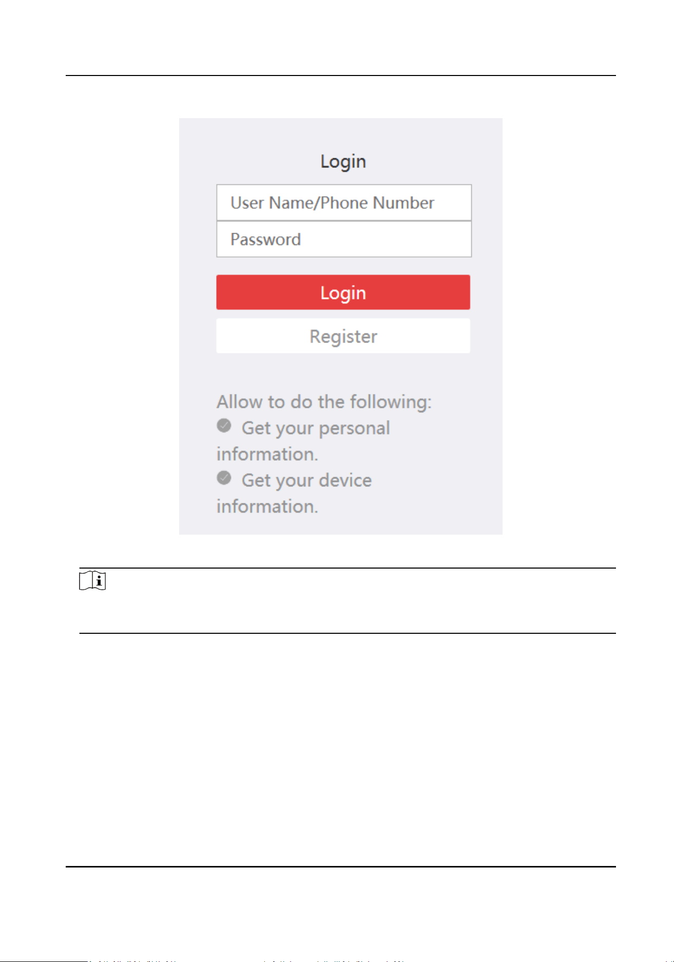
Figure 2-1 Log in Cloud Account
Note
●
You should register an account for rst login.
●
Aer login, you can store the device in the cloud.
3.
Run the client soware, click Device Management → Device → Online Device. The device in the
LAN will be displayed.
4.
Select an
inacve device. The inacve device’s security level is Inacve.
5.
Click Acvate and set the device password.
Security Radar User Manual
3
Cauon
●
STRONG PASSWORD RECOMMENDED-We highly recommend you create a strong password of
your own choosing (using a minimum of 8 characters, including upper case leers, lower case
leers, numbers, and special characters) in order to increase the security of your product.
●
And we recommend you reset your password regularly, especially in the high security system,
reseng the password monthly or weekly can beer protect your product.
●
The password cannot be the same as the user name or the reverse of the user name.
6.
Click OK.
The device’s Security Level will update toAcve.
7.
Select the
acvated device, click and change the device IP address, subnet mask, gateway.
Enter the acvaon password and click OK.
8.
Check the
acvaon devices and click Add.
2.2
Acvate via SADP
Download and install the SADP tool, search and acvate device.
Before You Start
Visit www.hikvision.com, search and gain SADP tool. Install the tool.
Steps
1.
Connect the device and PC with a network cable.
2.
Run the SADP tool and search the online device in the LAN.
3.
Select a device where the
acvaon status is Inacve.
4.
Set the device acvaon password and conrm the password.
Cauon
●
STRONG PASSWORD RECOMMENDED-We highly recommend you create a strong password of
your own choosing (using a minimum of 8 characters, including upper case leers, lower case
leers, numbers, and special characters) in order to increase the security of your product. And
we recommend you reset your password regularly, especially in the high security system,
reseng the password monthly or weekly can beer protect your product.
●
The password cannot be the same as the user name or the reverse of the user name.
5.
Click OK.
The device’s Security Level will update to
Acve.
6.
Select the acvated device, change the device IP address, subnet mask, gateway. Enter the
acvaon password and click Modify.
Security Radar User Manual
4
2.3 Acvate Device via Web
Use web browser to acvate the device.
Steps
1.
Make sure your device and your PC connect to the same LAN.
2.
If you connect the device with the PC directly, you need to change the IP address of your PC to
the same subnet as the device.
Note
Device default IP: 129.168.1.64. The IP address of the PC can be set as any IP between
192.168.1.2 and 192.168.1.254 (except for 192.168.1.64). For example, you can set the PC’s IP as
192.168.1.100.
3.
Open a web browser and input 192.168.1.64 in the address bar to enter the acvaon page.
4.
Set the device acvaon password and conrm the password.
Cauon
STRONG PASSWORD RECOMMENDED-We highly recommend you create a strong password of
your own choosing (using a minimum of 8 characters, including upper case leers, lower case
leers, numbers, and special characters) in order to increase the security of your product. And
we recommend you reset your password regularly, especially in the high security system,
reseng the password monthly or weekly can beer protect your product.
5.
Click OK.
6.
Enter the device password.
Security Radar User Manual
5

Chapter 3 Network Sengs
Set network parameters, port, address mapping, etc.
3.1 Network Parameters Sengs
3.1.1 Set IP Address
IP address must be properly congured before you operate the device over network. IPv4 and IPv6
are both supported. Both versions can be congured simultaneously without conicng to each
other.
Steps
1.
Select the radar and click
in the client soware, or enter the IP address of the radar in the
address bar of the web browser. Go to Conguraon → Network → Network Parameters →
Network Interface .
Security Radar User Manual
6
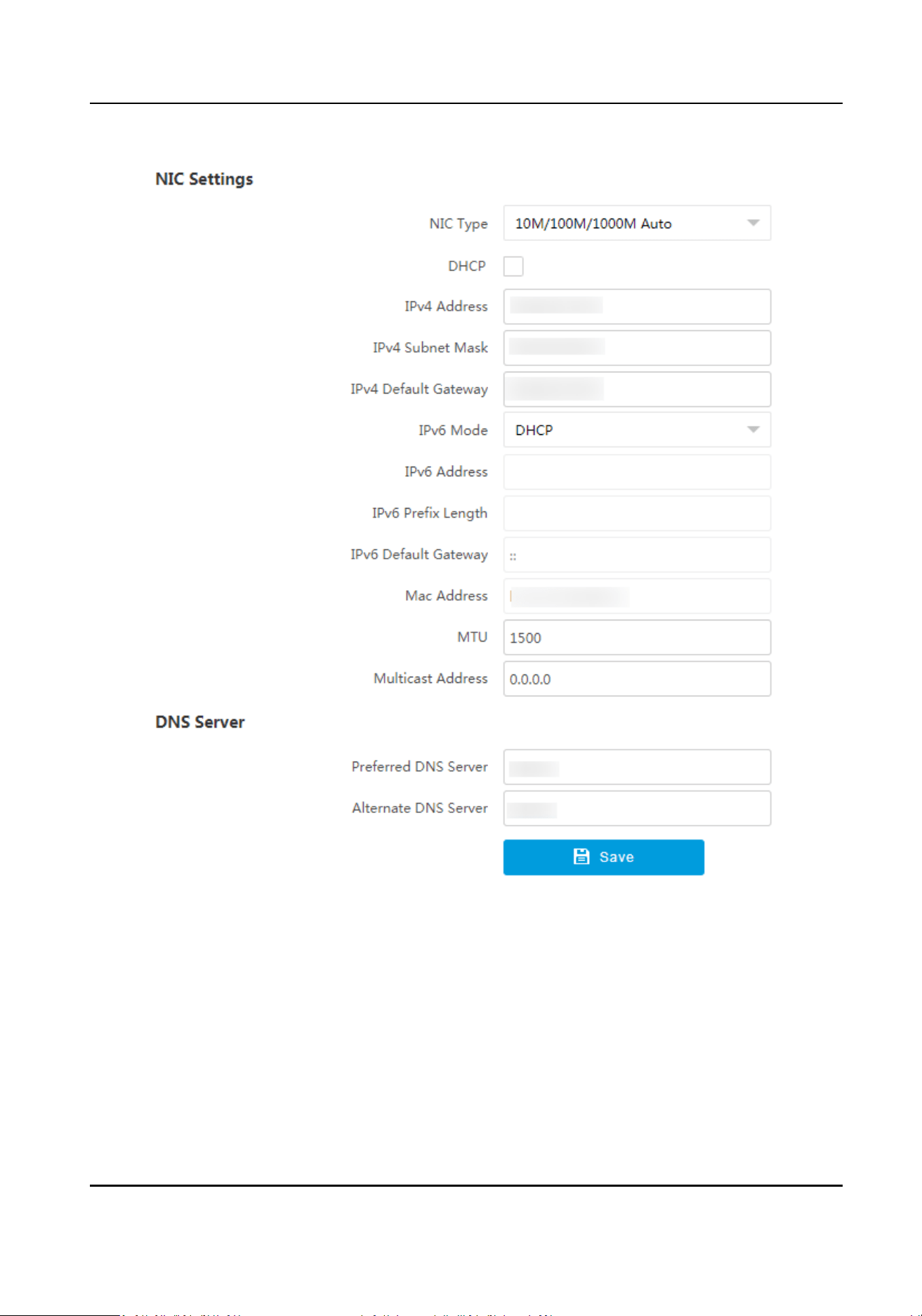
Figure 3-1 Set IP Address
2.
Set network parameters.
NIC Type
Select a NIC (Network Interface Card) type according to your network condion.
IPv4
Two modes are available.
DHCP
Security Radar User Manual
7
The device automacally gets the IP parameters from the network if you check DHCP. The
device IP address is changed aer enabling the funcon. You can use SADP to get the device
IP address.
Note
The network that the device is connected to should support DHCP (Dynamic Host
Conguraon Protocol).
Manual
You can set the device IP parameters manually. Enter IPv4 Address, IPv4 Subnet Mask, and
IPv4 Default Gateway.
IPv6
Three IPv6 modes are available.
Route
Adversement
The IPv6 address is generated by combining the route adversement and the device Mac
address.
Note
Route adversement mode requires the support from the router that the device is
connected to.
DHCP
The IPv6 address is assigned by the server, router, or gateway.
Manual
Enter IPv6 Address, IPv6 Subnet Mask, and IPv6 Default Gateway. Consult the network
administrator for required
informaon.
MTU
It stands for maximum transmission unit. It is the size of the largest protocol data unit that
can be communicated in a single network layer transacon.
The valid value range of MTU is 1280 to 1500.
Mulcast Address
Mulcast is group communicaon where data transmission is addressed to a group of
desnaon devices simultaneously. Aer seng the IP address of the mulcast host, you can
send the source data
eciently to mulple receivers.
DNS
It stands for domain name server. It is required if you need to visit the device with domain
name. And it is also required for some applicaons (e.g., sending email). Set Preferred DNS
Server and Alternate DNS Server properly if needed.
3.
Click Save.
Security Radar User Manual
8
3.1.2 Set Port
The device port can be modied when the device cannot access the network due to port conicts.
Select the radar and click in the client soware, or enter the IP address of the radar in the
address bar of the web browser. Go to Conguraon → Network → Network Parameters → Port .
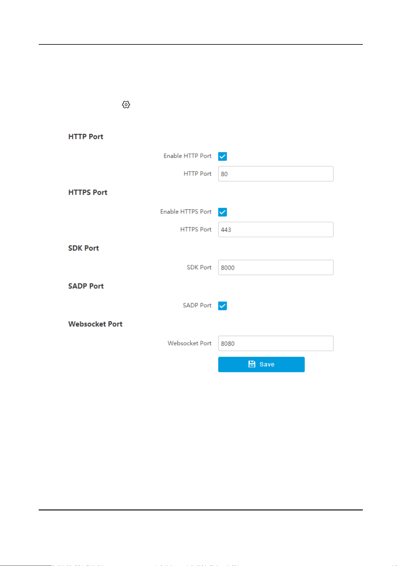
Figure 3-2 Set Port
HTTP Port
It refers to the port through which the browser accesses the device. For example, when the
HTTP Port is
modied to 81, you need to enter hp://192.168.1.64:81 in the browser for login.
HTTPS Port
It refers to the port through which the browser accesses the device, but cercate vericaon is
needed.
SDK Port
Security Radar User Manual
9
It refers to the port through which the client adds the device.
SADP Port
It refers to the port through which the SADP soware searches the device.
Websocket Port
It refers to the port that the device uses to access via the web browser. It ranges from 2 to
65534.
Note
●
Aer eding the port, access to the device via the new port.
●
Reboot the device to bring the new sengs into eect.
●
The supported ports vary with dierent models. The actual device prevails.
3.1.3 Set HTTPS
Install Authorized Cercate
If the demand for external access security is high, you can create and install authorized cercate
via HTTPS protocol to ensure the data transmission security.
Steps
1.
Select the radar and click in the client soware, or enter the IP address of the radar in the
address bar of the web browser. Go to Conguraon → Network → Network Parameters →
HTTPS .
2.
Select Create
cercate request rst and connue the installaon.
3.
Click Create.
4.
Follow the prompt to enter Country/Region, Domain/IP, Validity, and other parameters.
5.
Click Download to download the
cercate request and submit it to the trusted authority for
signature.
6.
Import cercate to the device.
-
Select Signed cercate is available, start the installaon directly. Click Browse and Install to
import the cercate to the device.
-
Select Create the cercate request rst and connue the installaon. Click Browse and
Install to import the cercate to the device.
7.
Click Save.
Create and Install Self-signed
Cercate
HTTPS is a network protocol that enables encrypted transmission and identy authencaon,
which improves the security of remote access.
Security Radar User Manual
10
Steps
1.
Select the radar and click in the client soware, or enter the IP address of the radar in the
address bar of the web browser. Go to Conguraon → Network → Network Parameters →
HTTPS .
2.
Select Create Self-signed Cercate.
3.
Click Create.
4.
Follow the prompt to enter Country/Region, Domain/IP, Validity, and other parameters.
5.
Click OK.
Result
The device will install the self-signed
cercate by default.
3.1.4 Set Address Mapping
The 2 network interfaces of the device communicate with the switch (external port) and the array
(internal port) respecvely, and do not communicate with each other. Aer adding an address
mapping, you can set the array
informaon through the external port.
Steps
1.
Select the radar and click in the client soware, or enter the IP address of the radar in the
address bar of the web browser. Go to Conguraon → Network → Network Parameters →
Address Mapping .
2.
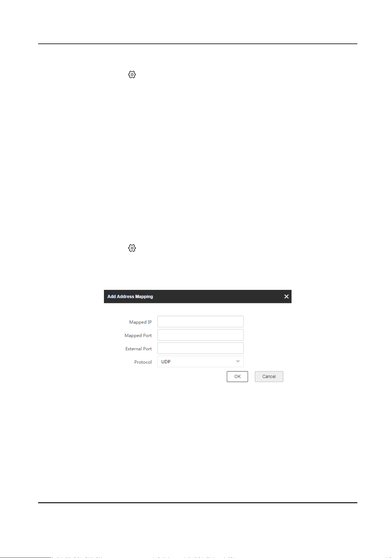
Click Add Mapping Rule.
Figure 3-3 Add Address Mapping
3.
Set the parameters, and click OK.
Mapped IP
The IP address of the internal radar module (array).
Mapped Port
The port of the internal radar module (array).
Security Radar User Manual
11
External Port
The port of the external control board (the device).
Protocol
Select the network transmission protocol according to the actual needs. TCP ensures
complete delivery of streaming data and beer video quality, but the real-me transmission
will be aected. UDP provides real-me audio and video streams.
4.
Slide to enable the added address mapping.
5.
Oponal: The other operaons.
Edit address
mapping
Click to edit the address mapping informaon.
Delete address
mapping
Click to delete the single address mapping. Or check the address
mappings to be deleted, and click Delete to delete them.
3.2 Data Connecon
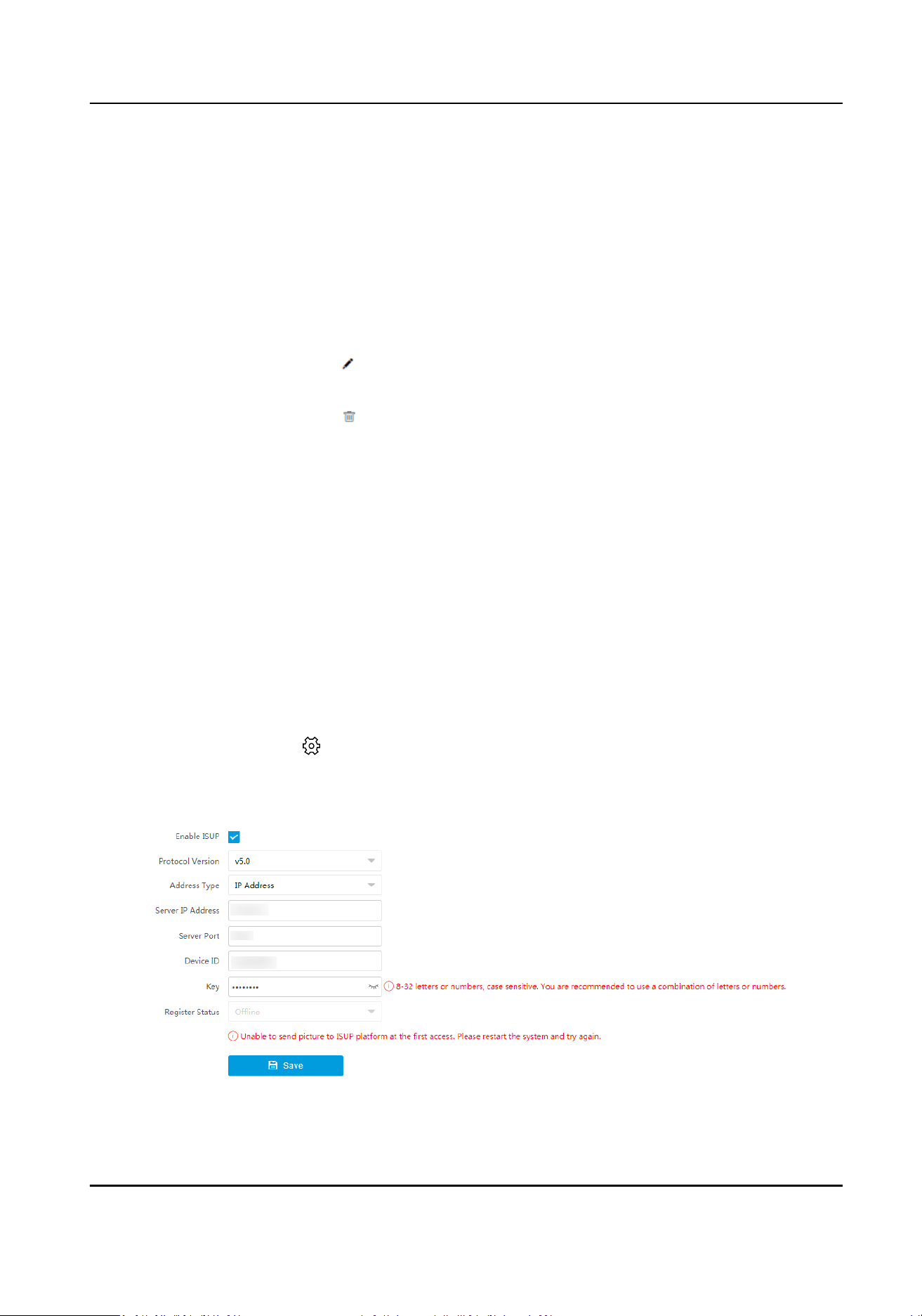
3.2.1 Connect to ISUP Plaorm
ISUP is a plaorm access protocol. The device can be remotely accessed via this plaorm.
Before You Start
●
Create the device ID on ISUP
plaorm.
●
Ensure the device can communicate with the plaorm normally.
Steps
1.
Select the radar and click in the client soware, or enter the IP address of the radar in the
address bar of the web browser. Go to
Conguraon → Network → Data Connecon → ISUP .
2.
Check Enable ISUP.
Figure 3-4 Connect to ISUP Plaorm
Security Radar User Manual
12
3.
Select Protocol Version.
4.
Select Address Type.
5.
Enter Sever IP Address/Server Domain Name, Server Port, and Device ID.
Note
The device ID should be the same with the one created via the plaorm.
6.
Enter Key.
7.
Click Save.
8.
Oponal: View Register Status.
Note
Aer the device is added successfully on the ISUP plaorm, the registraon status will show
online. Refer to the plaorm user manual for details.
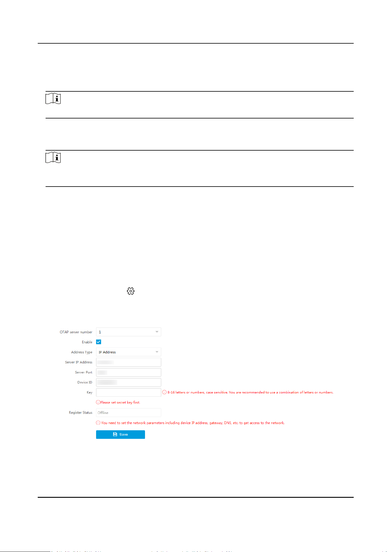
3.2.2 Connect to OTAP Plaorm
The device can be accessed to the maintenance plaorm via OTAP protocol, in order to search and
acquire device informaon.
Before You Start
●
Ensure the device can communicate with the plaorm normally.
●
Disable the other
plaorms conicted with OTAP.
Steps
1.
Select the radar and click in the client soware, or enter the IP address of the radar in the
address bar of the web browser. Go to Conguraon → Network → Data Connecon → OTAP .
2.
Check Enable.
Figure 3-5 Connect to OTAP
3.
Set corresponding parameters.
Security Radar User Manual
13
Note
The device ID should be the same with the added one on the OTAP plaorm.
4.
Click Save.
What to do next
When the registraon status is online, you can add or manage the device via the plaorm
soware.
Refer to its corresponding manual for details.
Security Radar User Manual
14
Chapter 4 Radar Sengs
You can add map, zones for the radar in the client soware or web client.
4.1 Radar Sengs via Web Browser
Edit maps, radars, zones, and trigger lines via web browser.
Note
●
You will be automacally logged out if you stay in the live view page for 2 hours without any
operaon.
●
You will be automacally logged out if you stay in the conguraon page for 5 minutes without
any
operaon.
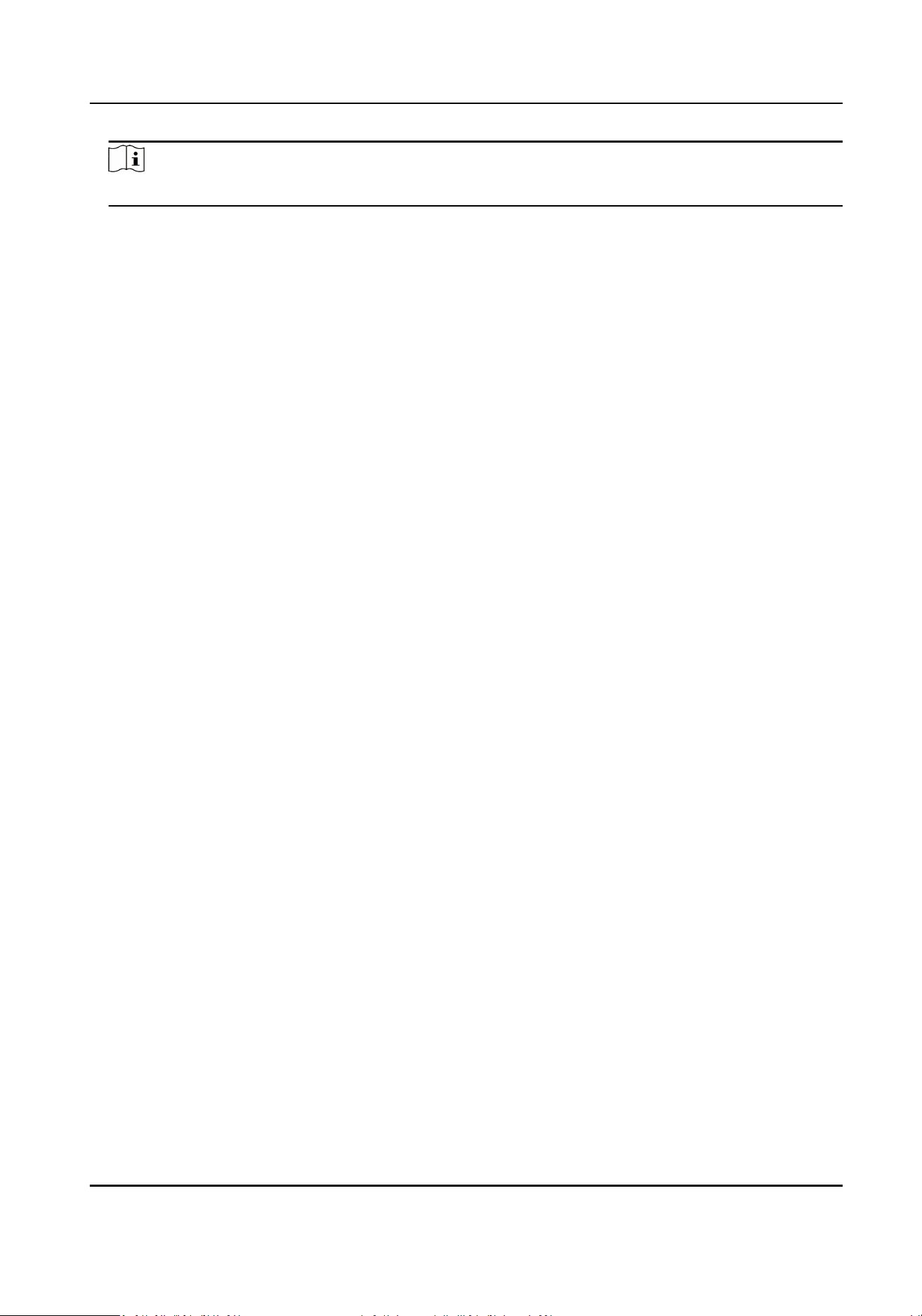
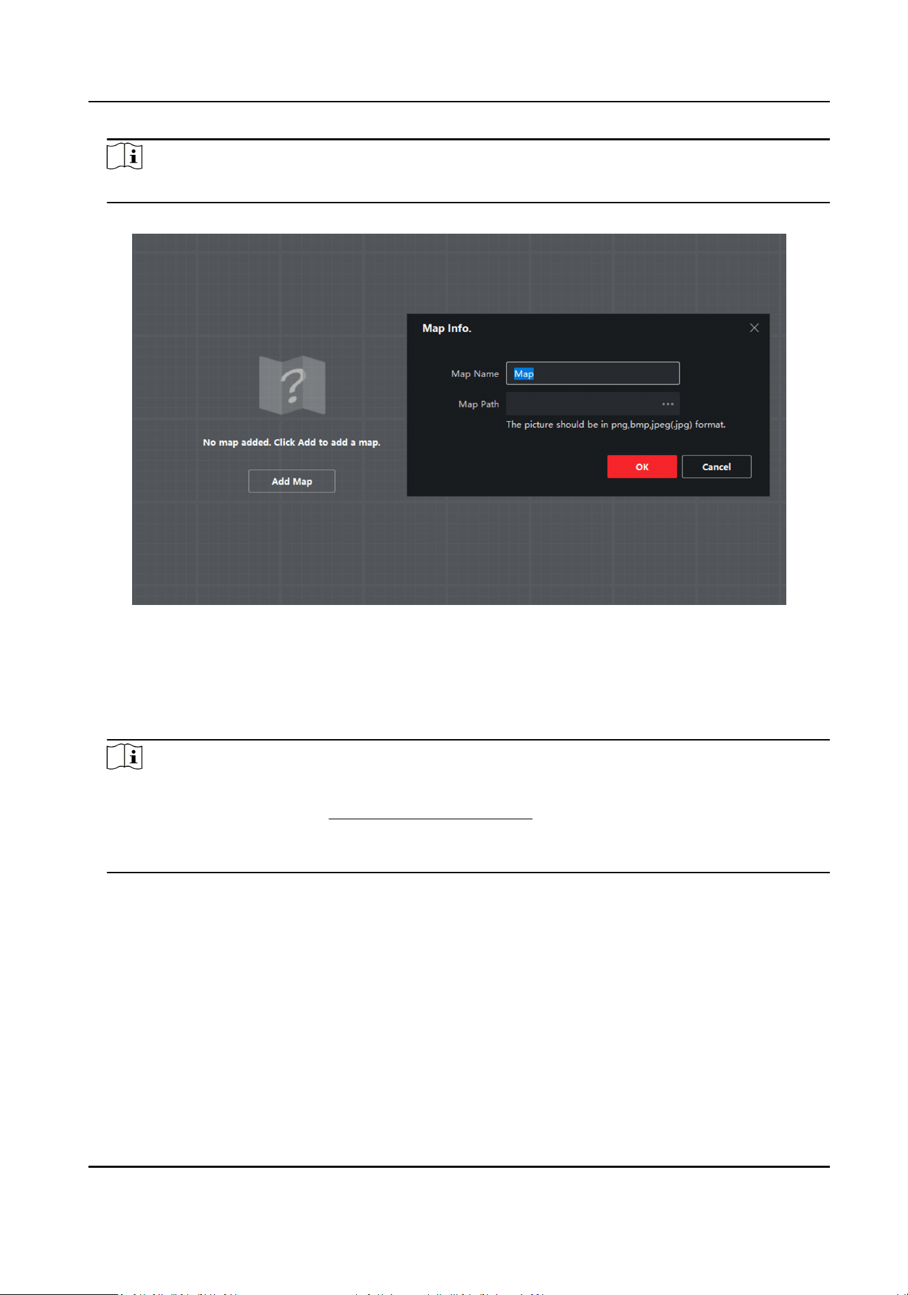
4.1.1 Add Map via Web Browser
You need to add a map to the radar via the web browser for subsequent conguraon.
Steps
1.
Enter the IP address of the radar in the web browser and log in. Click Radar to enter the page.
2.
Select Add Map from the dropdown list.
Figure 4-1 Entrance to Add Map
3.
Select a map to import, and click OK.
Note
The imported map should be less than 20 MB.
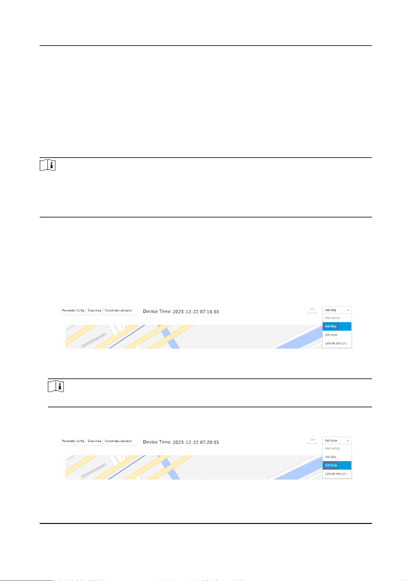
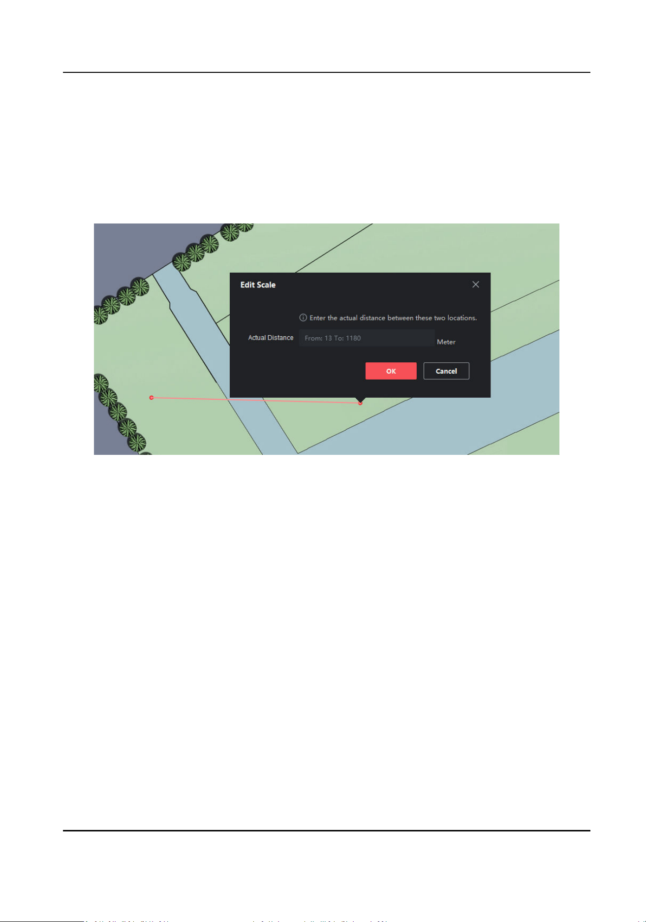
4.
Set the map scale.
1) Select Set Scale from the dropdown list.
Figure 4-2 Entrance to Set Map Scale
Security Radar User Manual
15
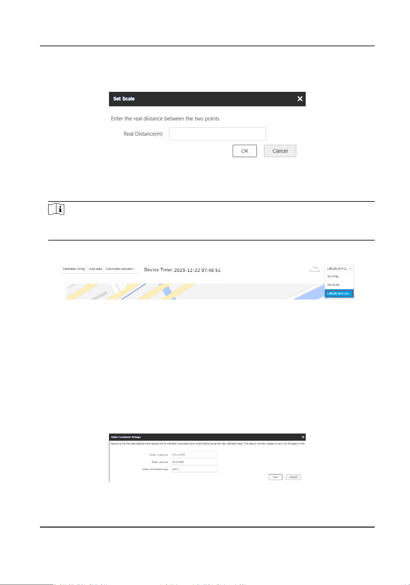
2) Draw a straight line on the map.
3) Enter the actual distance between the two points.
Figure 4-3 Set Map Scale
4) Click OK.
5.
Set the radar longitude and
latude calibraon.
Note
When using latude and longitude calibraon, it is recommended to draw points whose
latudes and longitudes are conrmed on the map in advance.
1) Select Set Scale from the dropdown list.
Figure 4-4 Entrance for Longitude and
Latude Calibraon
2) Click + Add Calibraon Point and click on the map to generate the rst point. Enter the
latude and longitude of this point, accurate to 6 decimal places.
3) Click + Add
Calibraon Point and click on the map to generate the second point. Enter the
latude and longitude of this point, accurate to 6 decimal places.
4) Click Save
Calibraon on the top right corner.
5) Enter the radar latude and longitude and orientaon in the popup window.
Radar Orientaon
The radar orientaon is the clockwise angle between the true north direcon and the
radar center line. You can place your mobile phone on the back of the radar and use the
applicaon with compass funcon to get this angle.
Figure 4-5 Radar Coordinate
Sengs
Security Radar User Manual
16
6) Click Exit Calibraon.
6.
Adjust the radar posion. Drag the radar detecon area to move the radar posion. You can drag
the icon on the arc side of the sector to adjust the detecon direcon.
7.
Oponal: To arm or disarm the radar:
-
Click Radar Arm to arm the radar.
-
Click Radar Disarm to disarm the radar.
8.
Oponal: Enable Display Number. The radar will number the targets appearing on the radar
detecon area. The targets will be numbered from 1 to 128 in sequence. If all 128 numbers are
used, the number will start from 1 again.
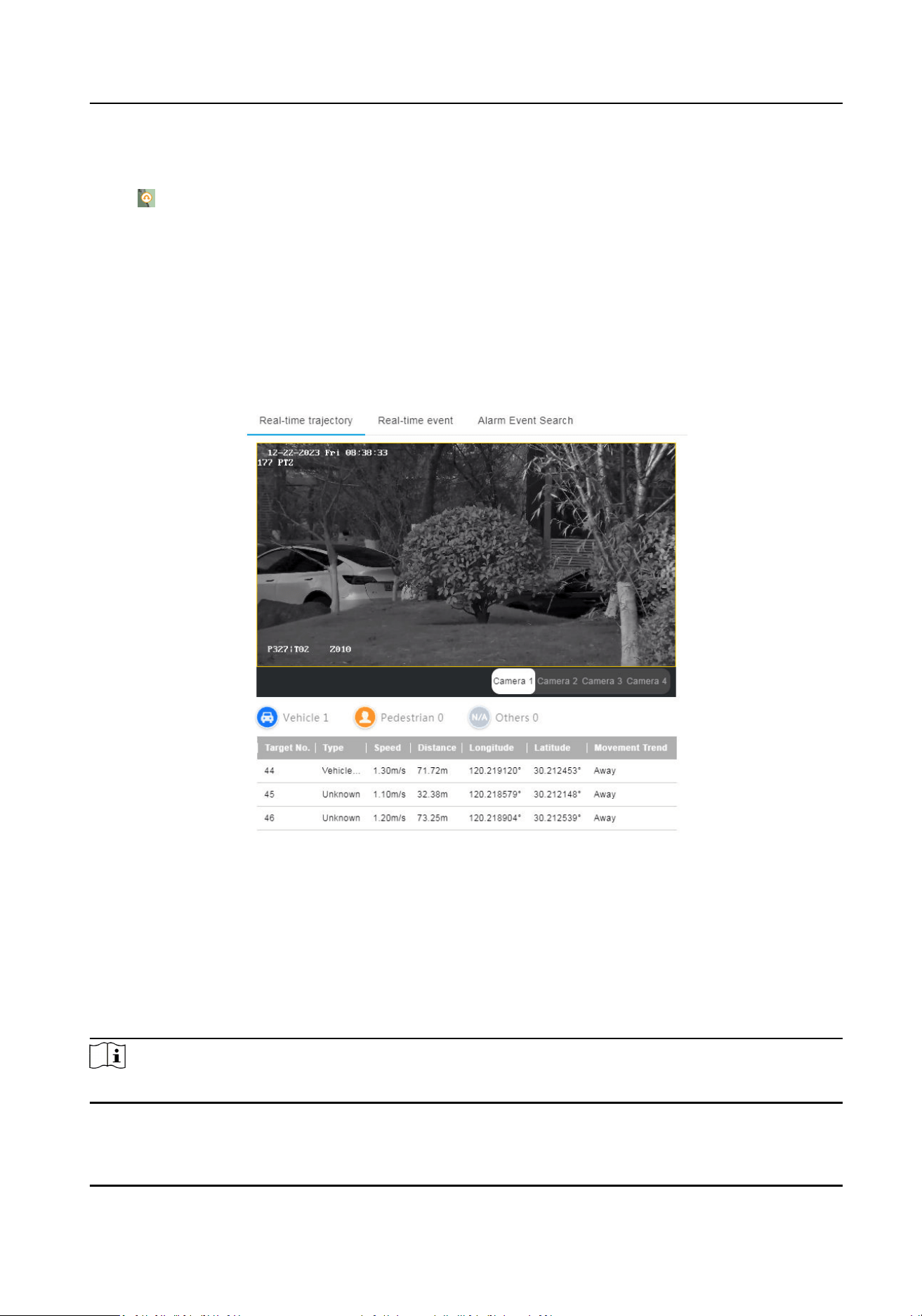
9.
Click
Real-me trajectory and select the camera to view the live view image and the recognized
target
informaon.
Figure 4-6 Real-Time Trajectory
4.1.2 Add Zone via Web Browser
Before You Start
Disarm the radar before adding a zone.
Steps
Note
Up to 16 zones can be added.
Security Radar User Manual
17
1.
Enter the IP address of the radar in the web browser and log in. Click Radar to enter the page.
2.
Oponal: Enable auxiliary. The target track will appear on the radar detecon area. You can
draw a zone with reference to the track. The track will be cleared aer the funcon is disabled.
3.
Oponal: Enable Display Number. The radar will number the targets appearing on the radar
detecon area. The targets will be numbered from 1 to 128 in sequence. If all 128 numbers are
used, the number will start from 1 again.
4.
Draw zones.
1) Click Start Drawing.
2) Click Draw Area → Draw Zone on the upper
le corner of the page.
3) Select Zone Sengs as Draw Zone.
4) Click the mouse
le buon to draw the zone in the radar detecon area and click the right
buon to end drawing.
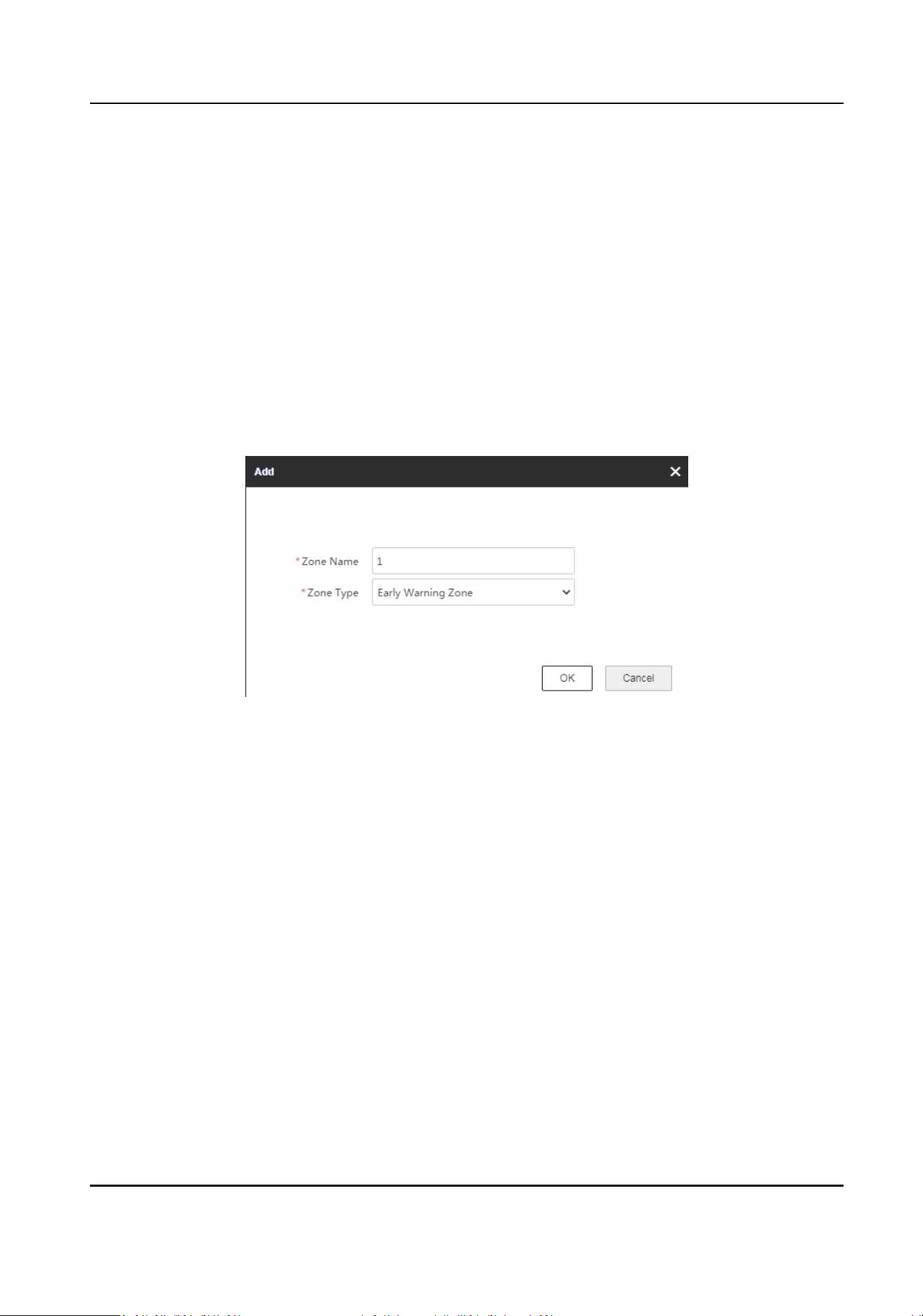
5) Set Zone Name and Zone Type in the popup window.
Figure 4-7 Add Zone
Early Warning Zone
The early warning zone will idenfy targets that have potenal risks in advance and trigger
alarm, but will not store alarm track. It is marked green on the map.
Warning Zone
The warning zone will
idenfy the targets entering the area and trigger alarm. It is marked
orange on the map.
Disabled Zone
The disabled zone will block the tracks of the targets entering into the zone. It is marked
gray on the map.
Security Radar User Manual
18
Note
●
The drawn zones can overlap. The priority of the eecve overlapping zone is: Disabled
Zone > Warning Zone > Early Warning Zone. That is, early warning zones can contain
warning zones and disabled zones, and warning zones can contain disabled zones.
●
You can zoom in/out to adjust the size of the displayed radar area.
●
The actual radar detecon area varies dierent radar models.
6) Oponal: Select Zone Sengs as Quick Zone. Click the mouse le buon to generate a
rectangle zone with the side length 1/5 of the
detecon distance automacally. You can drag
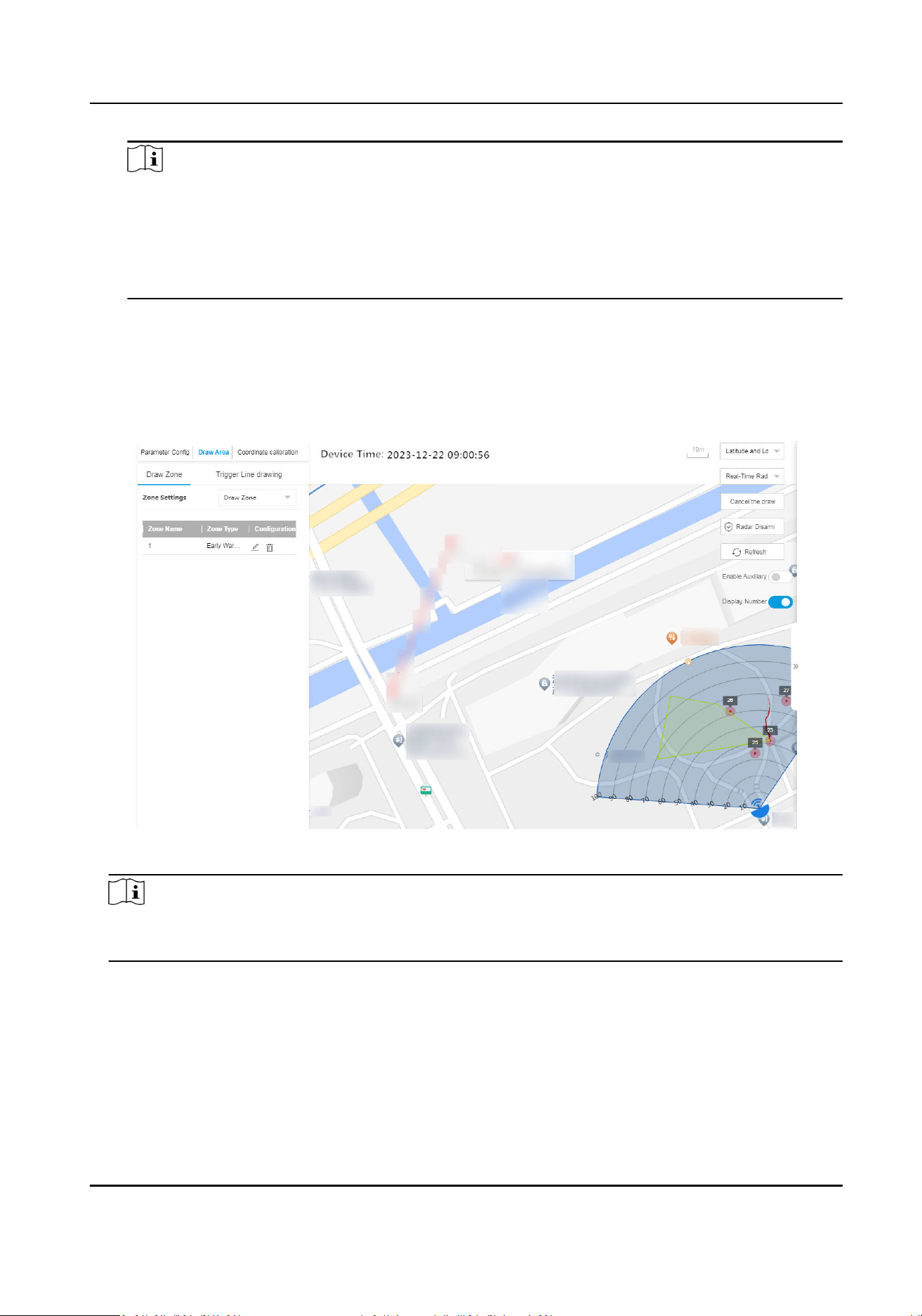
the zone to adjust its posion. Click the mouse right buon and Add Zone window will pop up
automacally. Set the zone name and type.
The added zones will display on the map.
Figure 4-8 Draw Zone
Note
Hover on the zone area under the non-eding mode, or click the zone under the eding mode,
the zone side length and name will be displayed.
5.
Oponal: Add a marker to the zone and edit the zone shape.
1) Double click the zone under the eding mode to enter the zone eding mode.
2) Put the cursor on the edge of the zone and it will change to a cross. Click to add a marker.
Security Radar User Manual
19
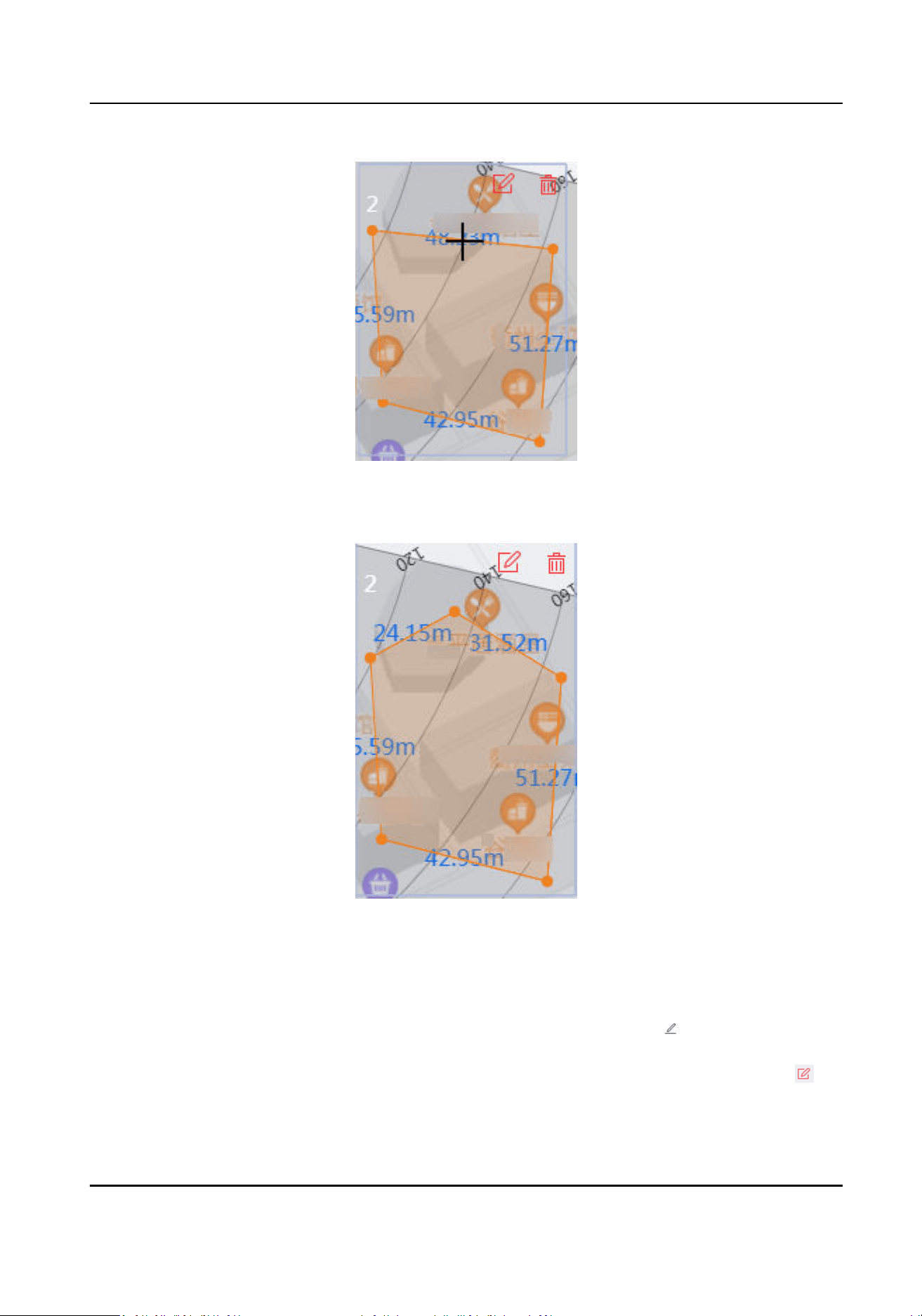
Figure 4-9 Add a Marker
3) Drag the marker to change the shape of the zone.
Figure 4-10 Drag a Marker
4) Hold to move the zone.
5) Click outside the zone to exit the zone
eding mode.
6.
Oponal: Edit the zone informaon or delete the zone.
Edit zone
informaon
●
In the zone list of Draw Area → Draw Zone , click to edit the zone
informaon.
●
In eding mode, double click the drawn area on the map, and click to
edit the zone
informaon.
Security Radar User Manual
20

Delete zone
●
In the zone list of Draw Area → Draw Zone , click to delete the zone.
●
In eding mode, double click the drawn area on the map, and click to
delete the zone.
4.1.3 Add Trigger Line via Web Browser
You can draw trigger lines for the radar zones and set the direcons of trigger lines.
Before You Start
Disarm the radar before adding a trigger line.
Steps
1.
Enter the IP address of the radar in the web browser and log in. Click Radar to enter the page.
2.
Draw a trigger line.
1) Click Start Drawing.
2) Click Draw Area → Trigger Line Drawing on the upper
le corner of the page.
3) Select Trigger Line
Cong.
Draw Trigger Line
To draw a single trigger line.
Draw Dual-trigger Line
To draw two trigger lines simultaneously.
Quick Trigger Line
Click the mouse le buon to generate a trigger line with the length 1/5 of the detecon
distance automacally. You can drag the line to adjust its posion.
Quick Dual-trigger Line
Click the mouse le buon to generate 2 trigger lines with the length 1/5 of the detecon
distance automacally. The distance between 2 trigger lines is 2 m. You can drag the lines
to adjust their posions.
4) Click the mouse le buon to draw the trigger line(s) in the radar detecon area and click the
right buon to end drawing.
5) Set Trigger Line name, Trigger Line Rule, and Distance in the popup window.
Security Radar User Manual
21
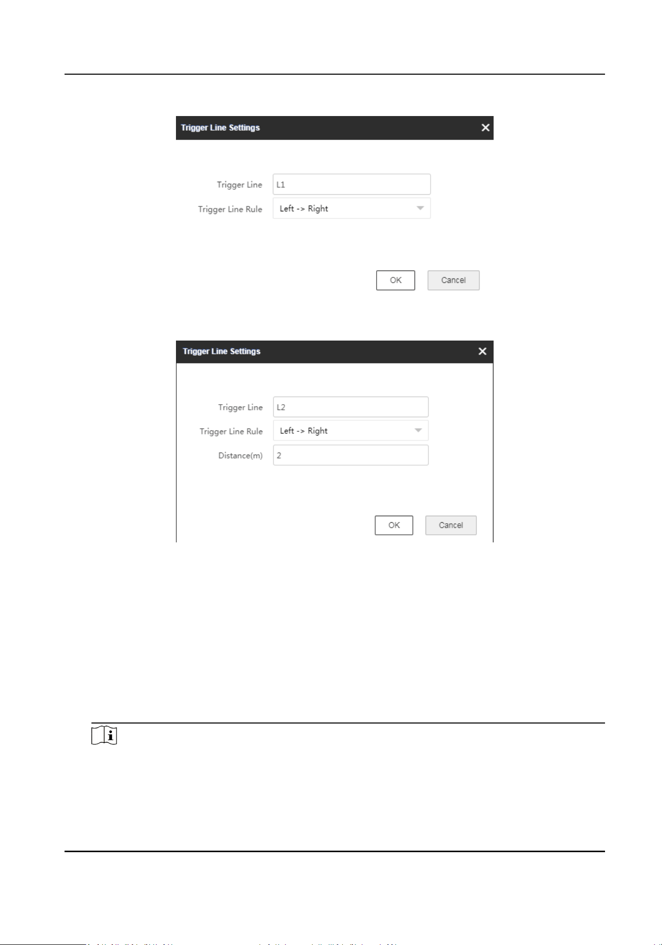
Figure 4-11 Set Trigger Line (Single Line)
Figure 4-12 Set Trigger Line (Dual Lines)
Trigger Line Rule
Direcon determinaon: Set the starng point as the center of the circle. The trigger line is
clockwise to the right, and counterclockwise to the le.
Trigger line rule: A single arrow -> indicates that the target will trigger an alarm when it
crosses the trigger line in the direcon of the arrow. A double arrow <-> indicates that the
target will trigger an alarm when it crosses the trigger line in any direcon.
Distance
The distance between 2 trigger lines. It is only available for dual lines.
Note
●
Up to 4 trigger lines can be drawn. (1 dual-trigger line is equal to 2 trigger lines).
●
The trigger lines cannot cross with each other.
Security Radar User Manual
22
●
Drawing a dual-trigger line that is too tortuous will cause a failure.
●
The alarm can be triggered by crossing the trigger line according to the single trigger line
rule. The alarm can be triggered only aer crossing 2 lines of dual-trigger lines according to
the trigger line rule.
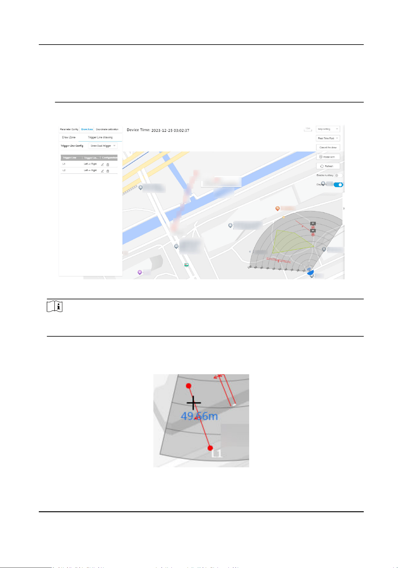
The added trigger lines will display on the map.
Figure 4-13 Draw Trigger Line
Note
Hover on the trigger line under the non-eding mode, or click the line under the eding mode,
the line length will be displayed.
3.
Oponal: Add a marker to the trigger line and edit the trigger line shape.
1) Double click the trigger line under the
eding mode to enter the trigger line eding mode.
2) Put the cursor on the trigger line and it will change to a cross. Click to add a marker.
Figure 4-14 Add a Marker
Security Radar User Manual
23
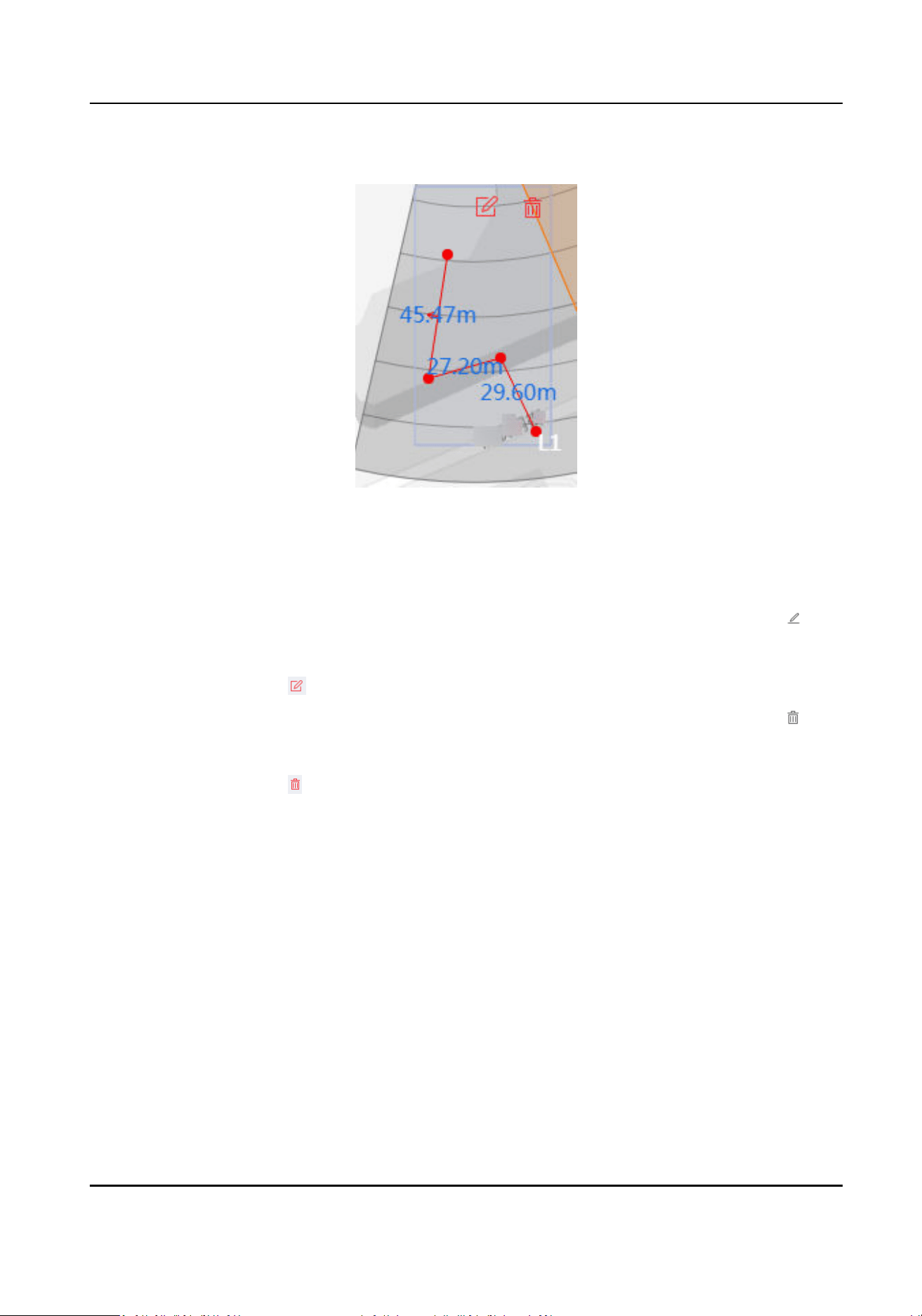
3) Drag the marker to change the shape of the trigger line.
Figure 4-15 Drag a Marker
4) Hold to move the trigger line.
5) Click outside the trigger line to exit the trigger line
eding mode.
4.
Oponal: Edit the trigger line informaon or delete the trigger line.
Edit trigger line
informaon
●
In the trigger line list of Draw Area → Trigger Line Drawing , click to
edit the trigger line informaon.
●
In eding mode, double click the drawn trigger line on the map, and click
to edit the trigger line informaon.
Delete zone
●
In the trigger line list of Draw Area → Trigger Line Drawing , click to
delete the trigger line.
●
In eding mode, double click the drawn trigger line on the map, and click
to delete the trigger line.
4.2 Radar Sengs in the Client Soware
Edit radar parameters in the client soware.
4.2.1 Add Map via Client
Soware
You should add a map of the detecon area in the E-map module to make sure the radar’s
installaon posion and the real geographic posion match with each other.
Steps
1.
Click E-map in the client soware to enter the radar page.
2.
Select the group of the radar.
3.
Click Add Map and select a map.
Security Radar User Manual
24
Note
Supported picture formats: jpg/png/bmp/jpeg.
Figure 4-16 Add a Map
4.
Click OK.
5.
Click Map
CalibraonLongitudeLatude Calibraon or Map CalibraonEdit Scale to ensure the
map scale.
6.
Oponal: Ensure the map scale by LongitudeLatude Calibraon.
Note
●
You should calibrate the latude and longitude of the radar on the web side rst. Refers to the
specic calibraon steps in Add Map via Web Browser .
●
When using latude and longitude calibraon, it is recommended to draw points on the map
that
conrm latude and longitude in advance.
1) Click Map Calibraon → LongitudeLatude Calibraon on the upper-right corner of the page.
2) Click +Add
Calibraon Point and click on the map to generate the rst point. Fill in the
latude and longitude of this point, accurate to 6 decimal places. Click Save in the lower-right
corner of the pop-up window.
3) Click +Add
Calibraon Point and click on the map to generate the second point. Fill in the
latude and longitude of this point, accurate to 6 decimal places. Click Save in the lower-right
corner of the pop-up window.
4) Click Save in the top-right corner.
Security Radar User Manual
25
5) Drag the radar into the map, and if the latude and longitude calibraon has been performed
on the web, the radar will automacally go to its posion. If it is not calibrated, an error will
be displayed.
7.
Oponal: Ensure the map scale by Edit Scale.
1) Click Map
Calibraon → Edit Scale on the upper-right corner of the page.
2) Draw a straight line on the map.
3) Enter the actual distance between the two points.
Figure 4-17 Edit Scale
4) Click Save.
8.
Oponal: Edit map sengs.
-
Click Update Map → Delete Map on the upper-right corner of the page to delete the map.
The added hot spots (radar for instance) and hot regions will be deleted as well.
-
Click Update Map → Edit Map on the upper-right corner of the page to change the map.
4.2.2 Add the Radar to the Map
Aer adding the map, you need to add a radar to the map.
Before You Start
●
Make sure that you have added the radar (when adding the device, check Import to Group to
the client
soware, as well as the map.
●
Mulple radars need to be added to the same group before they can be added to the same map.
Steps
1.
On the E-map page, click Edit in the upper right corner of the map to enter the eding mode.
2.
Expand the device group in the
le list, and then drag the radar onto the map.
Security Radar User Manual
26
Note
The actual radar detecng area varies according to dierent radar model.
3.
Adjust the radar posion. Drag the radar icon to make the radar detecon area cover the
required
led. You can rotate the sector with the icon on the arc side of the sector.
Note
You can drag the red slider in the lower right corner on the map to adjust the range of displayed
map, and click +/- to adjust the size of displayed map. Click to reset the map.
4.
Oponal: Click to delete radar or click to edit radar parameters.
Menu Descripon
Hot Spot Name Radar Name
Heat Spot Color Color of radar name
Heat Spot Icon The default icon cannot be changed
Apply to Other Radar Hot Spots Aer checking, the changes will be synchronized to other
radars.
5.
Click Finish in the upper right corner of the map to exit the eding mode, and the radar is xed.
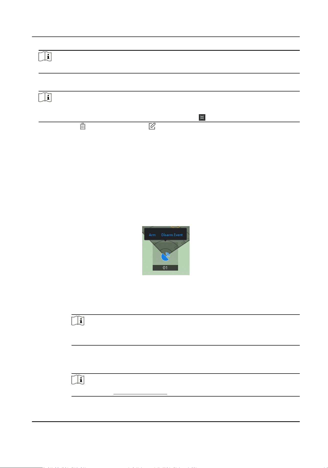
6.
Oponal: Aer exing the eding mode, click the radar icon and a menu appears above the
radar icon.
Figure 4-18 Radar Menu
Menu Descripon
Arm Open the arming mode of the radar detecon area.
Note
If there is a target in the warning zone when arming, a prompt will appear: There
are targets in the zone, enable mandatory arming?, and click OK to arm.
Disarm Close the arming mode of the radar detecon area.
Event Search and play back alarm events.
Note
For details, see Search Alarm Event .
Security Radar User Manual
27
7.
Oponal: Aer exing the eding mode, click Arm/Disarm → Arm all Radars or Arm/Disarm →
Disarm all Radars in the upper right corner of the map to arm/disarm all radars on the map.
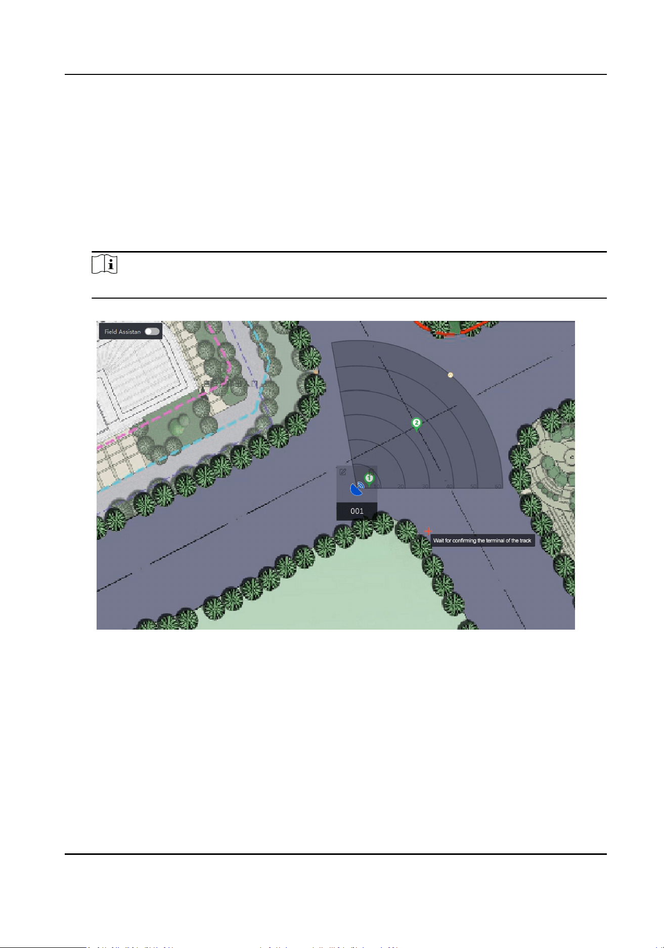
8.
Oponal: In eding mode, you can make map calibraon.
1) Click Edit to enter the eding mode.
2) Click Radar
Sengs → Map Calibraon.
3) Ask 2
calibraon stas to move into the radar detecon area. Select their tracks on the
detecon area. Calibrator stas stop at the calibraon points and the system will generate 2
markers at the terminal of tracks. Click OK on the pop-up window to conrm the track or click
Delete and select a new track.
Note
The actual radar detecng area varies according to dierent radar model.
Figure 4-19 Conrm Terminals
4) Click on the map to conrm the actual locaons of marker 1 and marker 2.
Security Radar User Manual
28
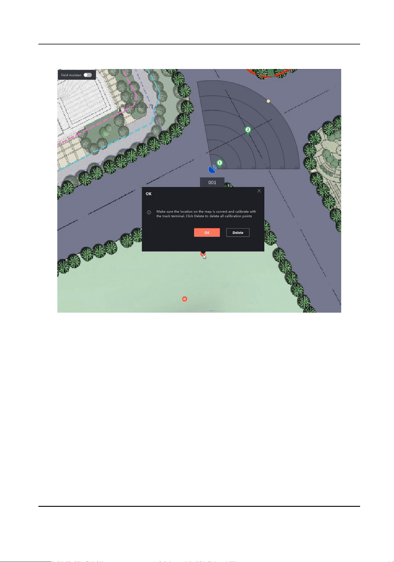
Figure 4-20 Conrm Actual Locaons
5) Click OK on pop-up window. The system will automacally match the markers to the actual
locaons. Click Delete to delete all calibraon points. Click OK and the system will
automacally match the markers to the actual posion on the map.
Security Radar User Manual
29
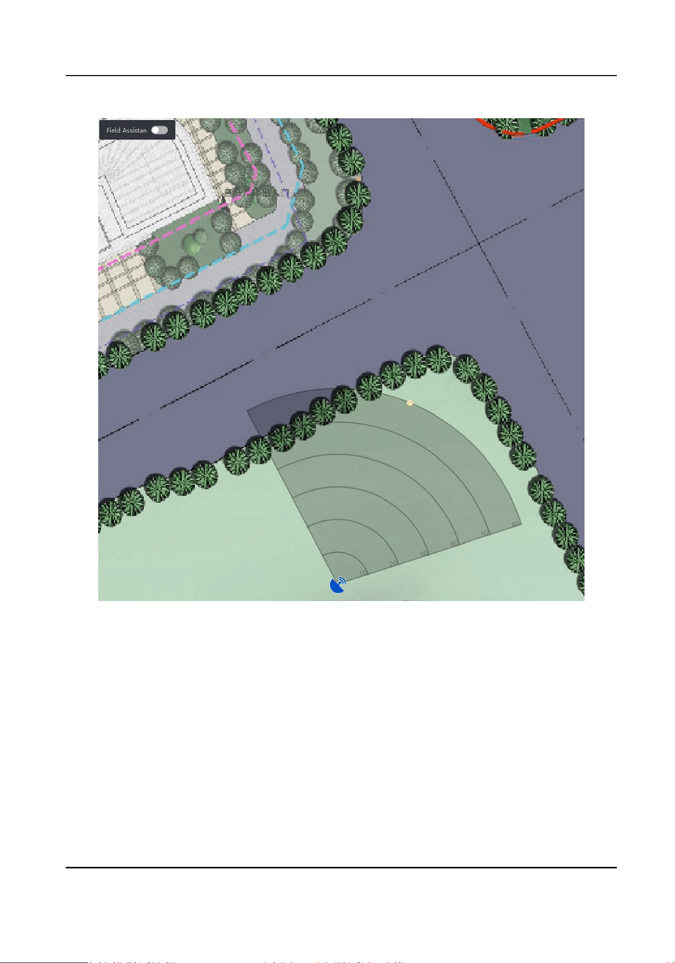
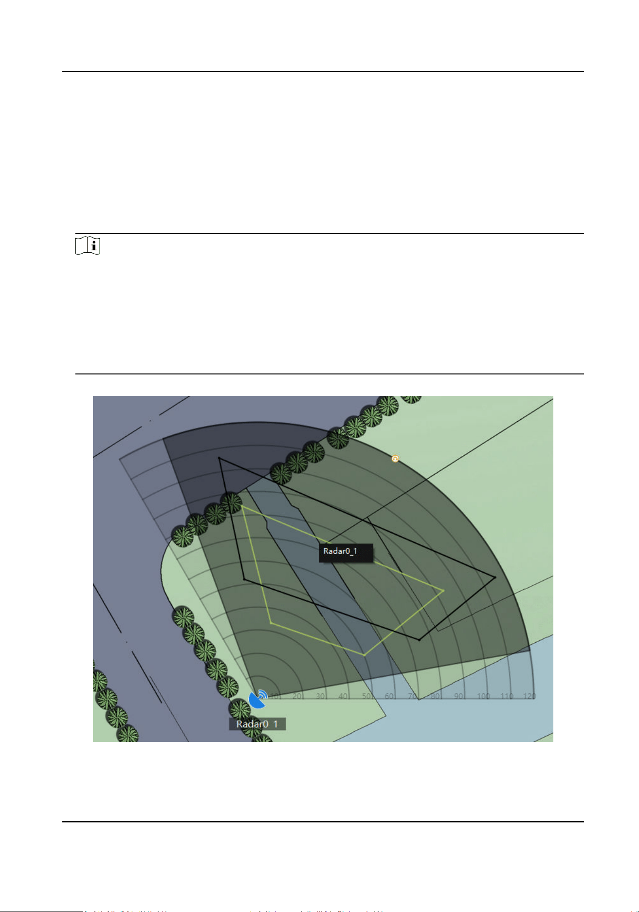
Figure 4-21 Finish Map Calibraon
6) Click Radar Sengs → End Map Calibraon.
4.2.3 Add Radar Zone via Client
Soware
Before You Start
You need to disarm the radar before the operaon. Click Finish in the E-map page to exit the
eding mode. Click on the radar icon and select Disarm to disarm the radar.
Steps
1.
In the client soware, click E-map.
2.
Click Edit to enter the eding mode.
Security Radar User Manual
30
3.
Oponal: Enable Field Assistan in the upper le corner of the map. The target track will appear
on the radar detecon area. You can draw a zone with reference to the track. The track cleared
when disabled.
4.
In the E-map page, click Radar
Sengs → Draw Zone Manually. Drag to draw a zone on the
radar
detecon area. You can also click Draw Zone Manually → Quick Zone to draw a quick
zone.
Quick Zone
Aer clicking, a zone with a side length of 1/5 of the detecon distance will be generated.
Note
●
Adding zones is a batch operaon. If you only add zones to one radar, you need to right-click
on the remaining radar detecon zones and click Cancel.
●
Zones can overlap, the priority of the eecve overlapping zone is: Disabled Zone>Warning
Zone>Early Warning Zone. That is, Early Warning Zone can contain Warning Zone and Disabled
Zone, and Warning Zone can contain Disabled Zone.
●
You can click +/- to zoom in/out the displayed radar area. Make sure the drawn detecon area
is cover the acture detecon area.
Figure 4-22 Overlap Zones
Security Radar User Manual
31
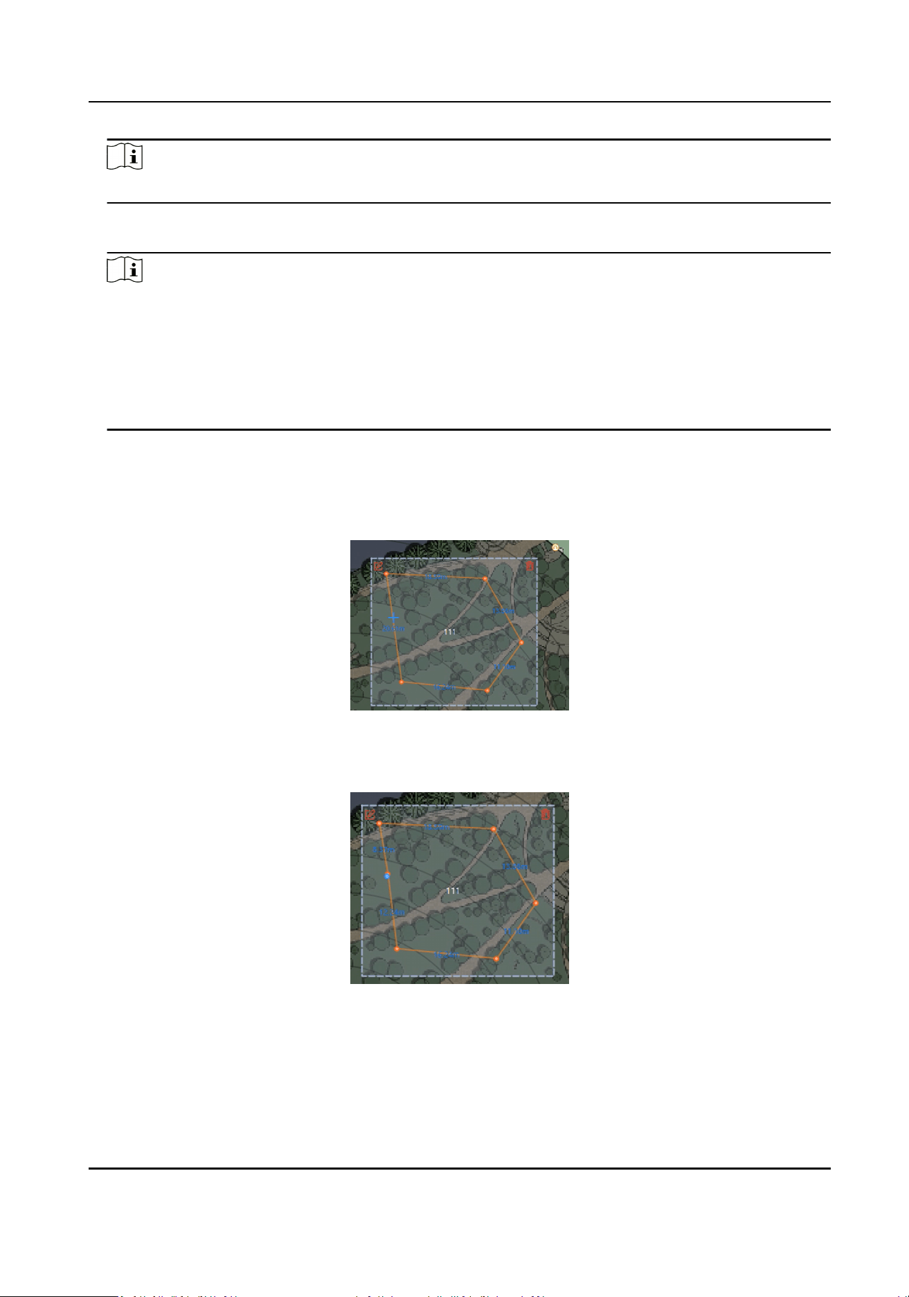
Note
The actual radar detecon area varies according to dierent radar model.
5.
Right-click to complete drawing, and the system will pop up a window. Enter the zone name, and
select Early Warning Zone, Warning Zone, or Disabled Zone as the zone type.
Note
●
Early Warning Zone: The early warning zone will idenfy target that has potenal risks in
advance and trigger alarm, but will not store alarm track. The early warning zone is green.
●
Warning Zone: The warning zone will idenfy the targets entering the area and trigger alarm.
The warning zone is orange.
●
Disabled Zone: The disabled zone will block the target track into the area. rm. The disabled
zone is gray.
6.
Click OK.
7.
Oponal: Edit or delete the zone.
1) Double-click the zone to enter the zone eding mode.
2) Put the cursor on the edge of the zone and it will change to a cross, click to add a marker.
Figure 4-23 Add a Marker
3) Drag the marker to change the shape of the zone.
Figure 4-24 Drag a Marker
4) Hold to move the zone.
Security Radar User Manual
32
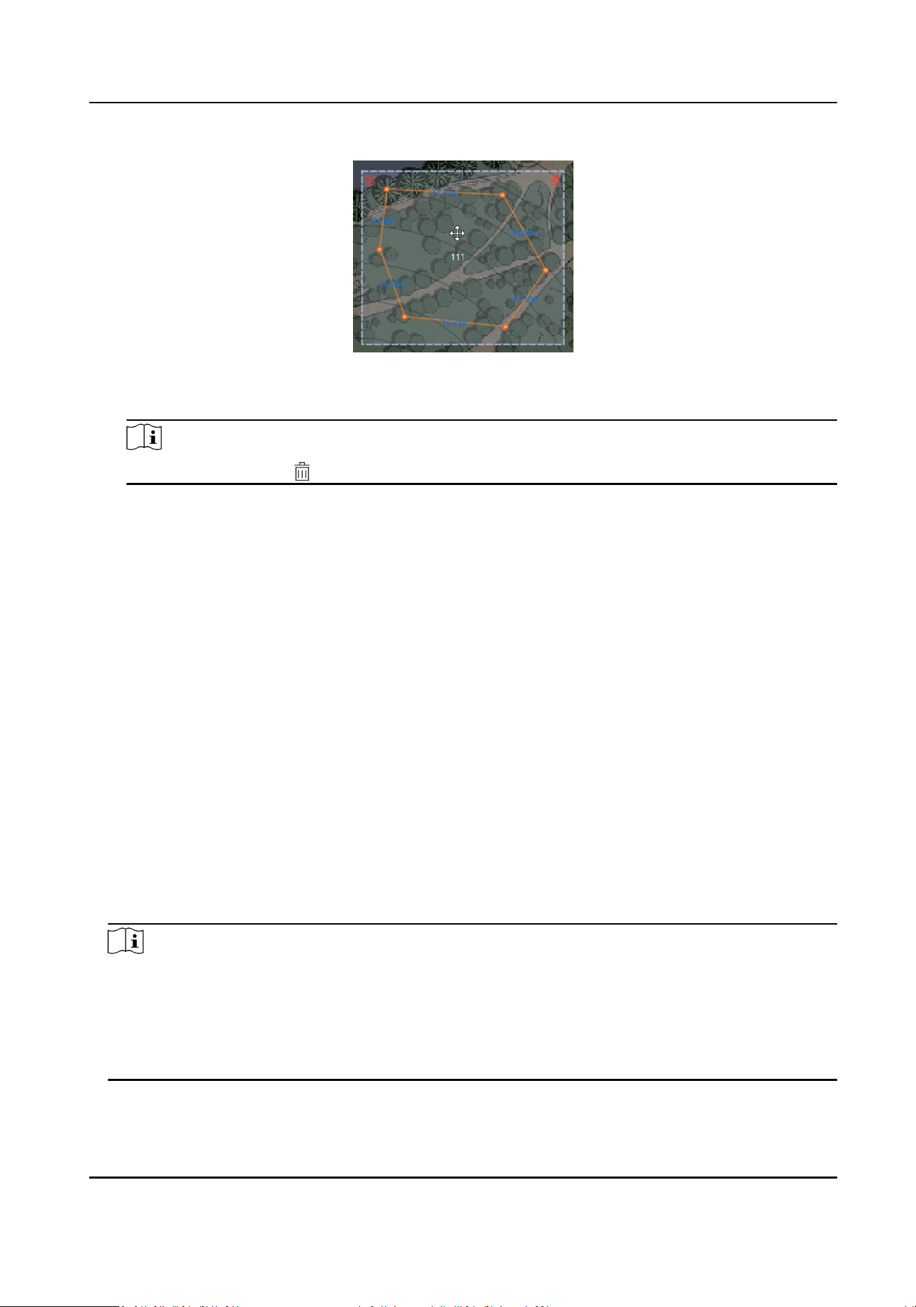
Figure 4-25 Move the Zone
5) Right-click outside the zone to exit the zone eding mode.
Note
To delete a zone, click in the top-right corner under the zone eding mode.
4.2.4 Add Trigger Line via Client Soware
You can draw trigger line for the radar's zone and set the trigger line’s direcon.
Before You Start
The radar is added to the map. Click Finish in the E-map page to exit the
eding mode. Click on the
radar and select Disarm to disarm the radar.
Steps
1.
On the E-map page, click Edit in the upper right corner of the map to enter the eding mode.
2.
Click Radar
Sengs → Draw Trigger Line. You can draw trigger line or dual-trigger line. You can
also click Draw Quick Trigger Line to draw quick single line or quick double line.
Quick Single Line
Aer clicking, a trigger line with the length of 1/5 of the detecon distance will be generated.
Quick Double Line
Aer clicking, a dual-trigger line with the length of 1/5 of the detecon distance will be
generated. The distance between 2 trigger lines is 2 m. You can drag the trigger line to any
posion.
Note
●
You can draw trigger line for all radars on the map.
●
Drawing a dual-trigger line that is too tortuous will cause a failure.
●
The alarm can be triggered by crossing the trigger line according to the trigger line rule; the
alarm can be triggered only
aer crossing double lines of dual-trigger line according to the
trigger line rule.
3.
Draw a trigger line.
Security Radar User Manual
33
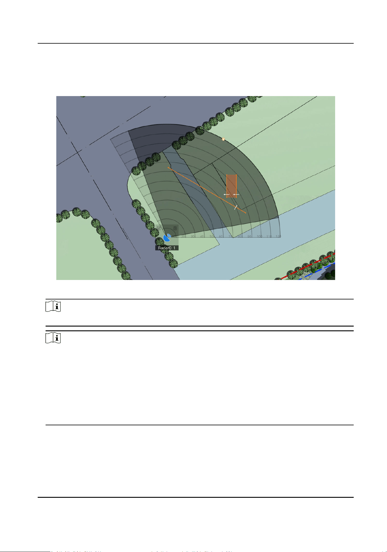
1) Click on the radar detecon area to draw a trigger line.
2) Select Le -> Right, Le <- Right or Le <-> Right in the pop-up window.
3) Enter the distance between two lines. (Only for Dual-trigger Line)
Figure 4-26 Draw a Trigger Line
Note
The actual radar detecon area varies according to dierent radar model.
Note
●
Direcon determinaon: Set the starng point as the center of the circle, the trigger line is
clockwise to the right, and counterclockwise to the le.
●
Up to 4 trigger lines can be drawn. (1 dual-trigger line is equal to 2 trigger lines)
●
Up to 1 dual-trigger line can be drawn.
●
Trigger line rule: A single arrow -> indicates that the target triggers an alarm when it crosses
the trigger line in the
direcon of the arrow; a double arrow <-> indicates that the target
triggers an alarm when it crosses the trigger line in any direcon.
●
The trigger line cannot cross each other.
4.
Click OK to complete the drawing.
5.
Oponal: Double click on the trigger line to enter the trigger line eding mode.
-
Add a Marker: Put the cursor on the edge of the zone and it will change to a cross, click to
add a marker.
Security Radar User Manual
34
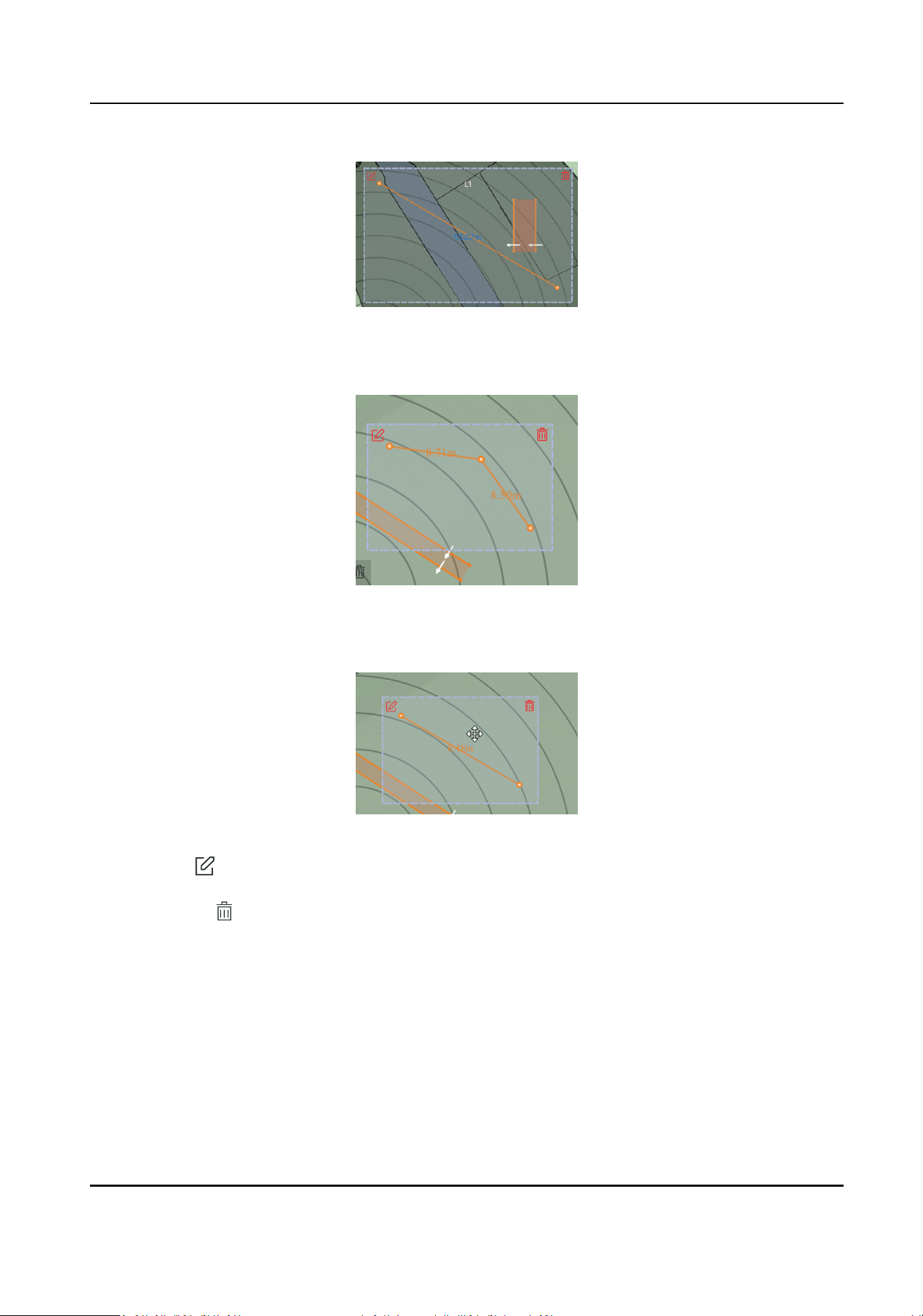
Figure 4-27 Add a Marker
-
Drag a Marker: Drag a marker on the trigger line to move it.
Figure 4-28 Drag a Marker
-
Move the Trigger Line: Hold the
eding area to move the trigger line.
Figure 4-29 Move the Trigger Line
-
Edit: tap to enter the page. Edit the trigger line name, trigger line rule and distance (only
for Dual-trigger Line).
-
Delete: tap to delete the trigger line.
4.2.5 Other Auxiliary
Funcons
Live View
In E-map page, click Finish to exit the eding mode. Click Live View and the live view window will
appear on the boom of the page. Drag the camera in the le list to the live view window and you
can view the video in real
me.
Security Radar User Manual
35
Speed Dome Field of View
Note
Before using this funcon, you need to conrm that the speed dome has been calibrated and the
speed dome has an linked zone.
In E-map page, click Finish to exit the
eding mode. Click Display → Camera FOV.
Aer enabled, you can see the target tracked by the currently linked speed dome.
OSD
In E-map page, click
Finish to exit the
eding mode. Click Display → Display OSD.
Aer enabled, the speed, distance, target type, and target similarity will be displayed on the live
view page.
Aer disabled, all informaon will note be displayed on the live view page except the radar
number.
Security Radar User Manual
36
Chapter 5 Camera Linkage
5.1 Set Speed Dome Inial Posion
Set the inial posion of the speed dome to ensure the tracking accuracy.
Steps
1.
Select a reference object about 50 m away from the speed dome. On the reference object,
select a reference point whose altude is the same as the speed dome's.
2.
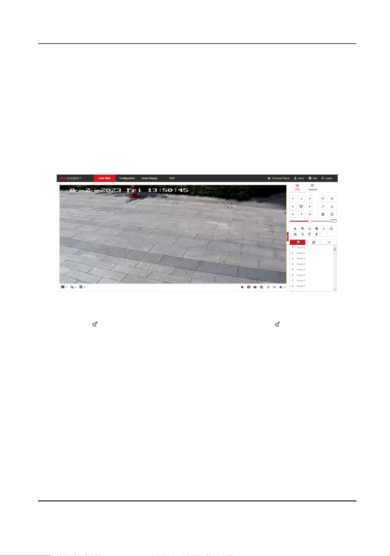
Enter the IP address of the speed dome in the web browser to enter the web client.
Figure 5-1 Camera live View Page
3.
Adjust the PTZ buons to make sure that the reference point is displayed in the live view
window. Click
to zoom in the reference point to the largest and click to enable 3D locaon.
Click the reference point and the point will be in the middle of the frame.
Security Radar User Manual
37
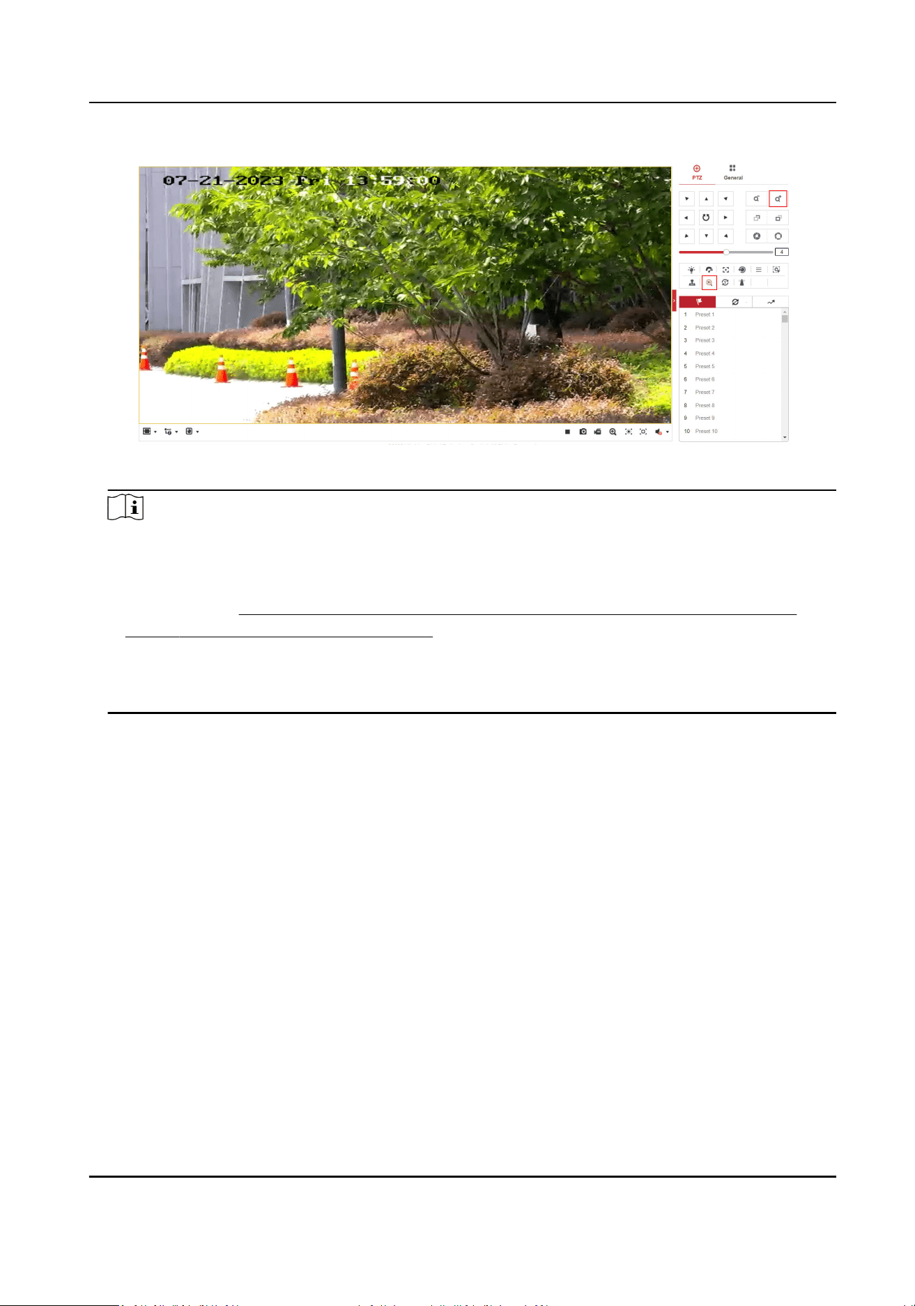
Figure 5-2 Reference Point Posion
Note
●
If the speed dome is installed lted, you may nd the reference point is above the center of
the frame or it is outside the frame when you adjust the camera PTZ. In this case, you should
adjust the maximum elevaon angle of the speed dome. For detail adjustment method,
please refer to
How to Solve the Problem that No Reference Point is on the Frame While
Seng the Speed Dome Inial Posion?
●
If the maximum elevaon angle of the speed dome is adjusted, the reference point needs to
be adjusted to the center of the frame again.
●
PTZ: Short for
pan/lt/zoom, which means move to up/down, le/right, and zoom.
4.
In the camera's web conguraon page, click Conguraon → PTZ → Inial Posion. Click Set
to set the
inial posion.
Security Radar User Manual
38
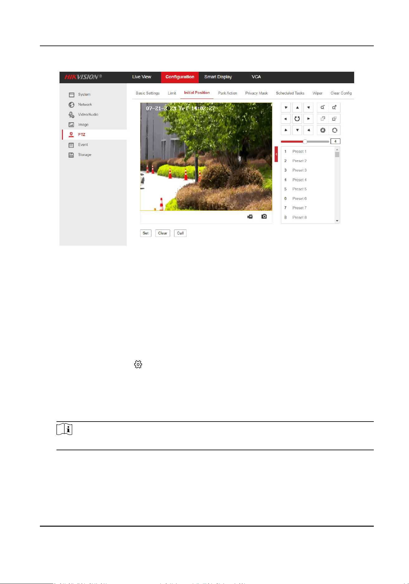
Figure 5-3 Set Inial Posion
5.2 Link Camera to Radar
Aer linking a camera, when there is an alarm of the camera, the linked zones and trigger lines will
trigger alarms.
Before You Start
Disarm the radar before linking a camera.
Steps
1.
Select the radar and click in the client soware, or enter the IP address of the radar in the
address bar of the web browser. Go to Radar → Coordinate
Calibraon → Link Camera .
2.
Add a camera.
1) Click + Add Camera in the camera list.
2) Enter the IP address, port, user name, password of the camera, and select whether to link to
NVR.
Note
To use the NVR for video storage, you can link the NVR and set the NVR parameters.
Security Radar User Manual
39
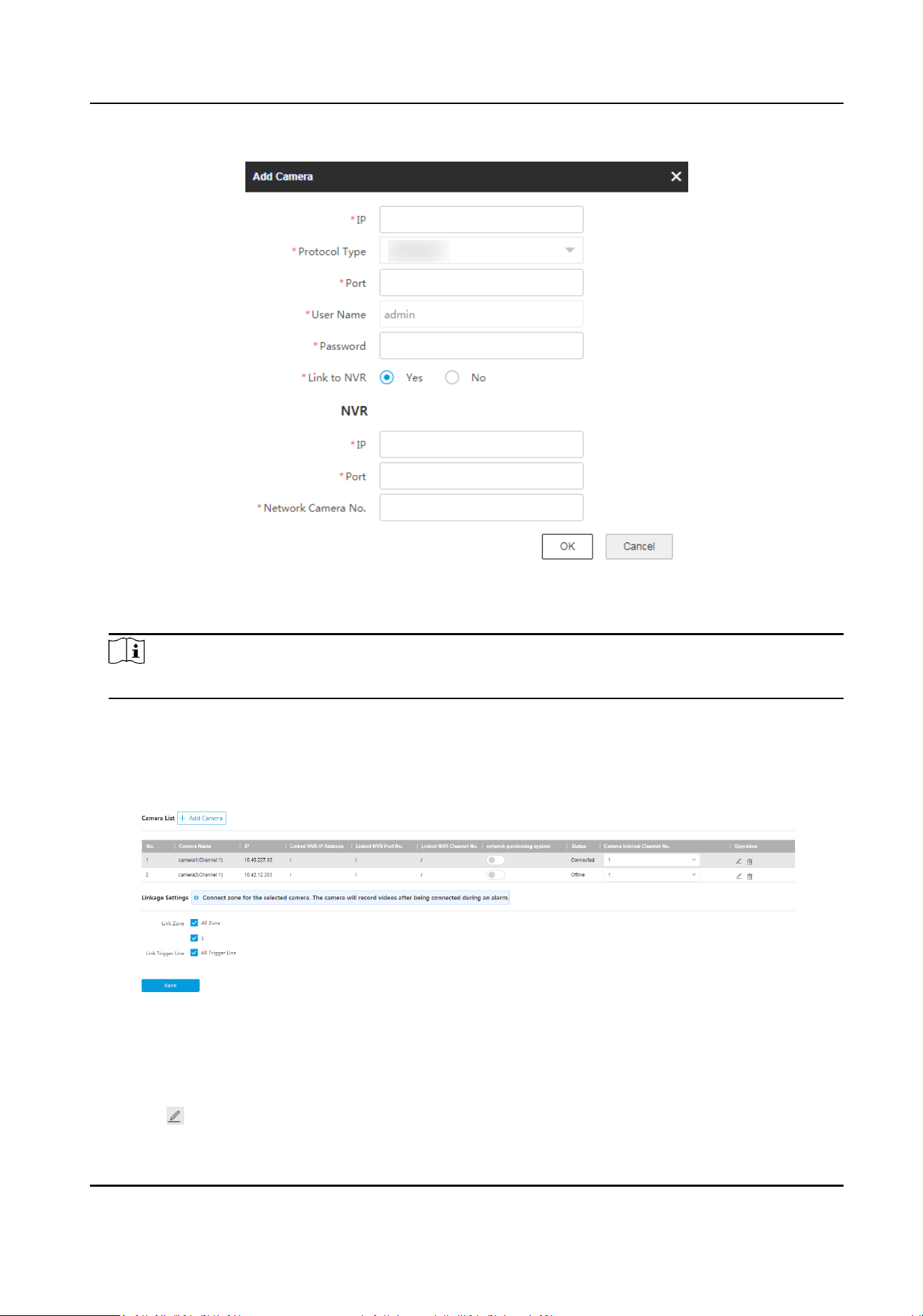
Figure 5-4 Add Camera
3) Click OK.
Note
Up to 4 cameras can be linked to 1 radar.
3.
Link zones and trigger lines to the camera.
1) Select a camera in the camera list.
2) Select zones and trigger lines to link in Linkage Sengs.
3) Click Save.
Figure 5-5 Link Camera
4.
Oponal: Edit the added camera in the camera list.
1) If the camera is a network posioning system, enable Network Posioning System.
2) Select Camera Internal Channel No.
3) Click
to edit the camera informaon.
Security Radar User Manual
40
4) Click to delete the camera.
5.3 Calibrate Camera
Calibrate the linked camera to ensure the accuracy of camera tracking.
Before You Start
●
You need to disarm the radar before the
operaon. Click Radar Disarm on Radar interface to
disarm the radar.
●
You need to link the speed dome to the zone before calibraon, and set the speed dome inial
posion.
●
The installaon height of the linked speed dome should be more than 3 m.
Steps
1.
Enter the IP address of the radar in the address bar of the web browser. Go to Radar →
Coordinate
Calibraon → Coordinate Calibraon .
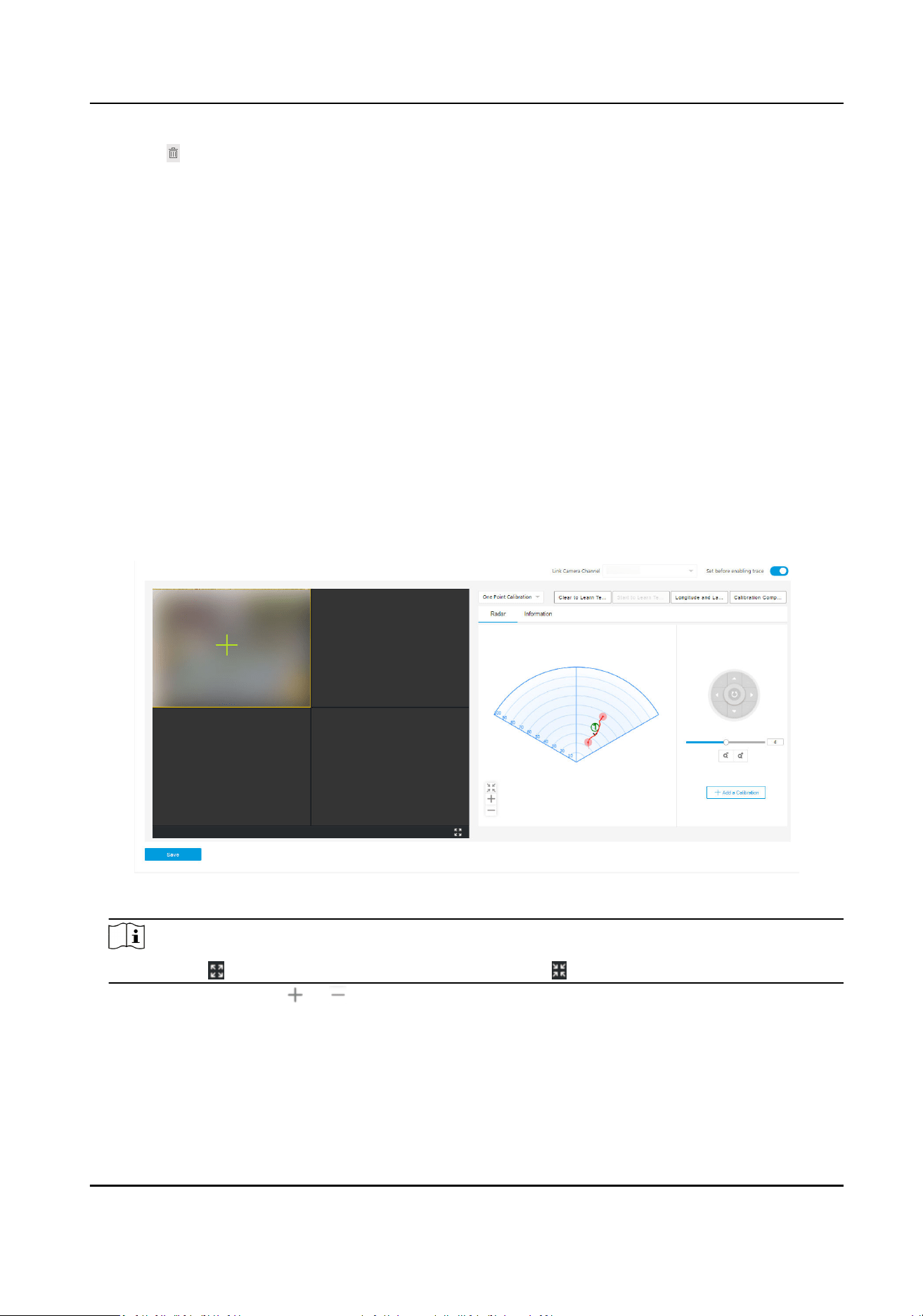
2.
Click a live view window and select Link Camera Channel. The live view window will show the
camera live view image.
Figure 5-6 Coordinate Calibraon
Note
You can click to maximum the selected window, or click to restore.
3.
Oponal: You can click or to adjust the radar detecon area.
4.
Select One Point Calibraon or Mul-point Calibraon.
Security Radar User Manual
41
Note
According to the relave installaon posion of the radar and the camera, it is necessary to set
the calibraon point according to the actual scene.
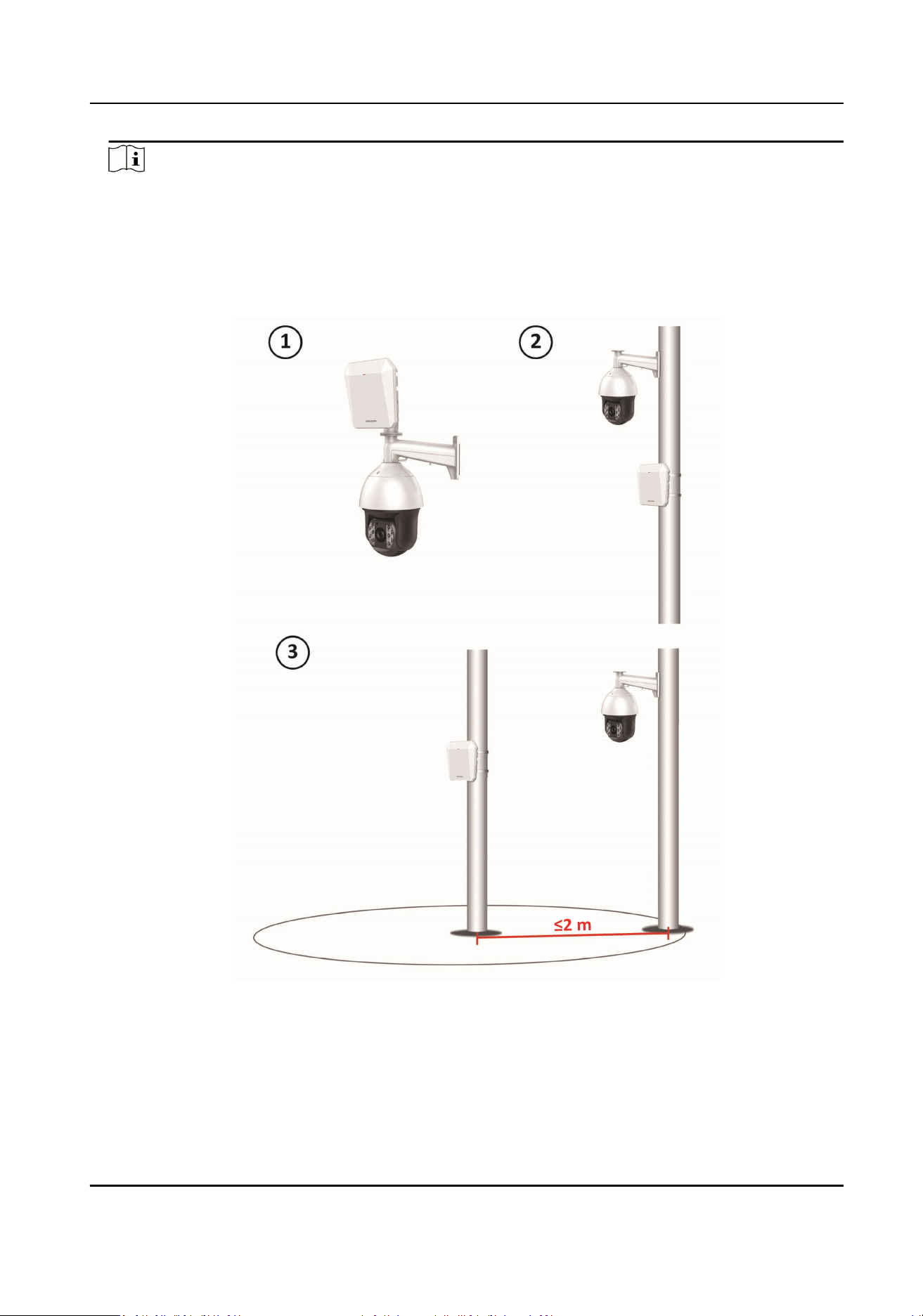
●
One Point Calibraon: Applicable to the scene where the radar and the camera are installed
on the same pole or the camera is installed within a radar-centered range of 2 m (regardless
of the altude dierence between the camera and the radar).
Figure 5-7 Installaon Scene for One Point Calibraon
●
Mul-point Calibraon: Applicable to the scene which is not applicable to the one-point
calibraon.
Security Radar User Manual
42
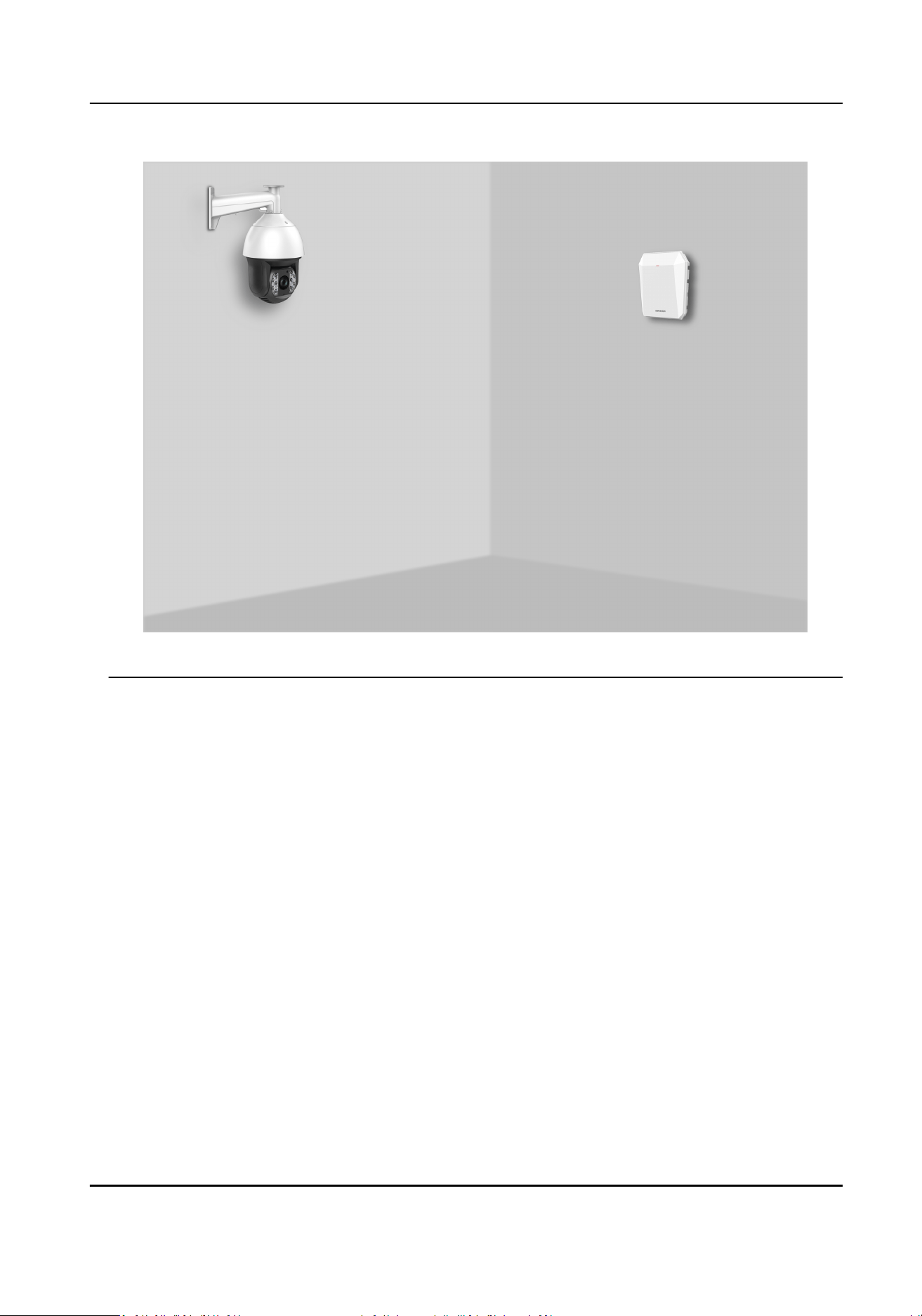
Figure 5-8 Installaon Scene for Mul-point Calibraon
5.
Calibrate the camera. According to the actual scene, calibrate the camera by one-point
calibraon or mul-point calibraon.
5.3.1 One Point
Calibraon
Before You Start
Arrange a
sta (operaon sta) to perform the calibraon operaon via the web browser, and a
sta (calibraon sta) to cooperate with the calibraon.
Steps
1.
Select One Point Calibraon as the calibraon mode.
2.
Select the track of
calibraon sta: Ask the calibraon sta to move into the radar detecon
area. Compare the moving object in the live view window of the camera and the track in the
radar
eld diagram. The operaon sta needs to select the track of the calibraon sta and click
it. The color of the selected track will change from red to white.
Security Radar User Manual
43
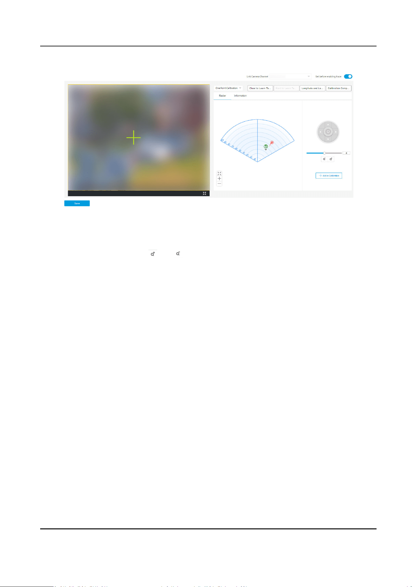
Figure 5-9 One Point Calibraon
3.
Ask the calibraon sta to move to the calibraon point within 20 to 40 m directly in front of the
radar, and then stand at the calibraon point.
4.
Adjust the PTZ
posion: Click and to adjust the altude of the calibraon sta to two-
thirds of the altude of the window, and click the direcon buons to align the central sign "+"
with the
calibraon sta. For precise alignment, click on the center of the object and the screen
will adjust automacally.
5.
Click Add a Calibraon to add a calibraon point. The PTZ posion and the radar posion of the
calibraon sta will be shown in the Informaon list. The opon Set before enabling trace will
be checked automacally.
Security Radar User Manual
44
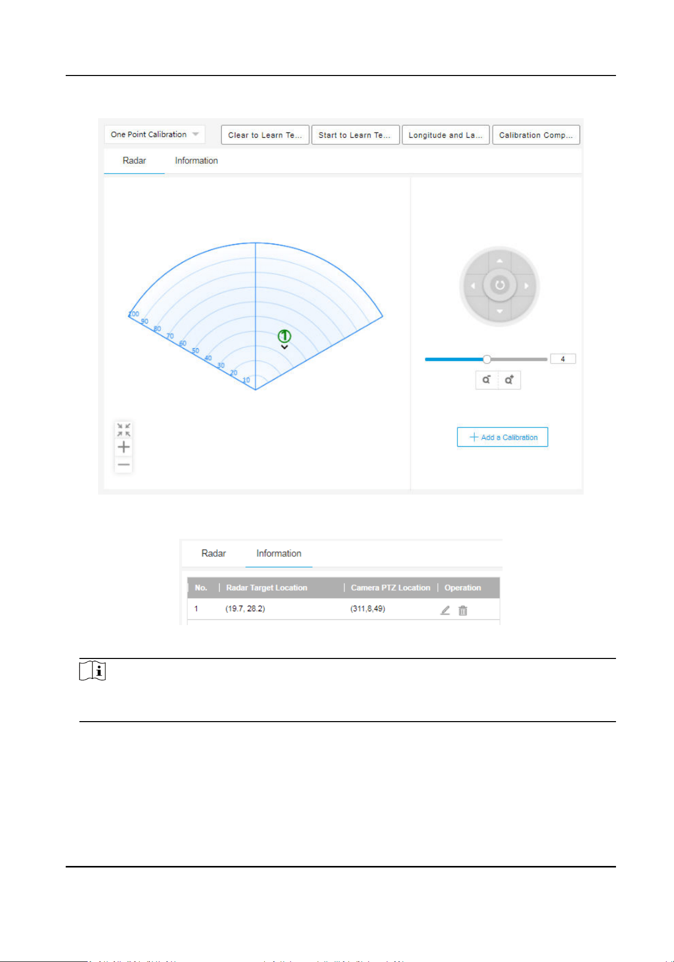
Figure 5-10 Add a Calibraon
Figure 5-11
Informaon List
Note
You should enable Network Poisoning System in Radar → Coordinate Calibraon → Camera
Calibraon if the camera is installed with PTZ.
6.
Click Save.
Security Radar User Manual
45
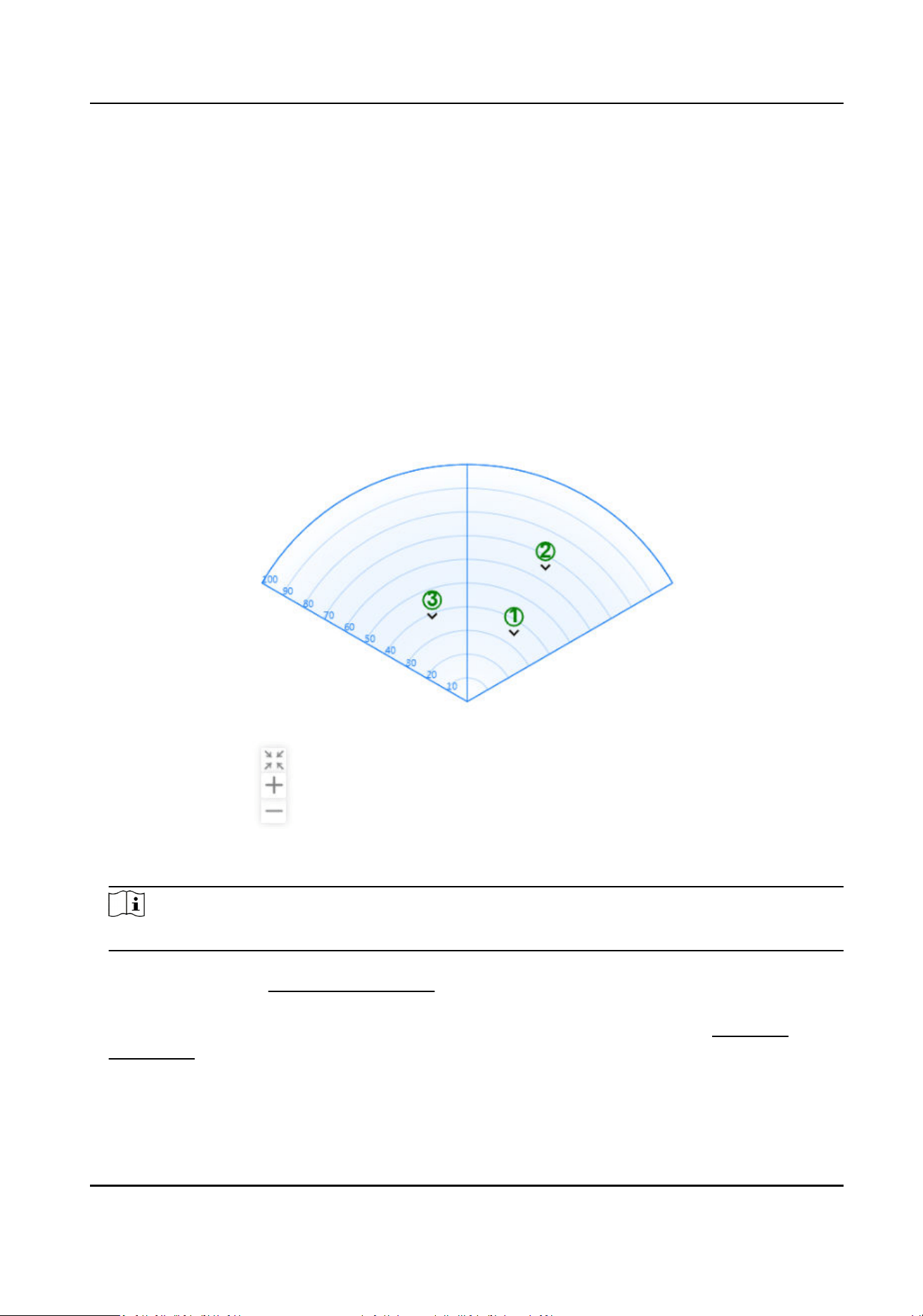
5.3.2 Mul-Point Calibraon
Before You Start
Arrange a
sta (operaon sta) to perform the calibraon operaon via the web browser, and a
sta (calibraon sta) to cooperate with the calibraon.
Steps
1.
Select Mul-Point Calibraon as the calibraon mode.
2.
Select
calibraon points (equally distributed) on the center line of the radar detecon eld. You
can refer to the following gure to select points.
Figure 5-12 Mul-Point Distribuon Instance
Note
It is required to set 3 calibraon points (equally distributed) for mul-point calibraon.
3.
According to the calibraon points, ask the calibraon sta to move to a calibraon point. Refer
to step 2 to step 5 in
One Point Calibraon to calibrate the calibraon point.
4.
When the rst calibraon point is calibrated completely, let the calibraon sta move to the
next
calibraon point aer the red track disappears. Refer to step 2 to step 5 in One Point
Calibraon to calibrate the calibraon point. Follow this process to complete all calibraon point
posioning in turn.
Security Radar User Manual
46
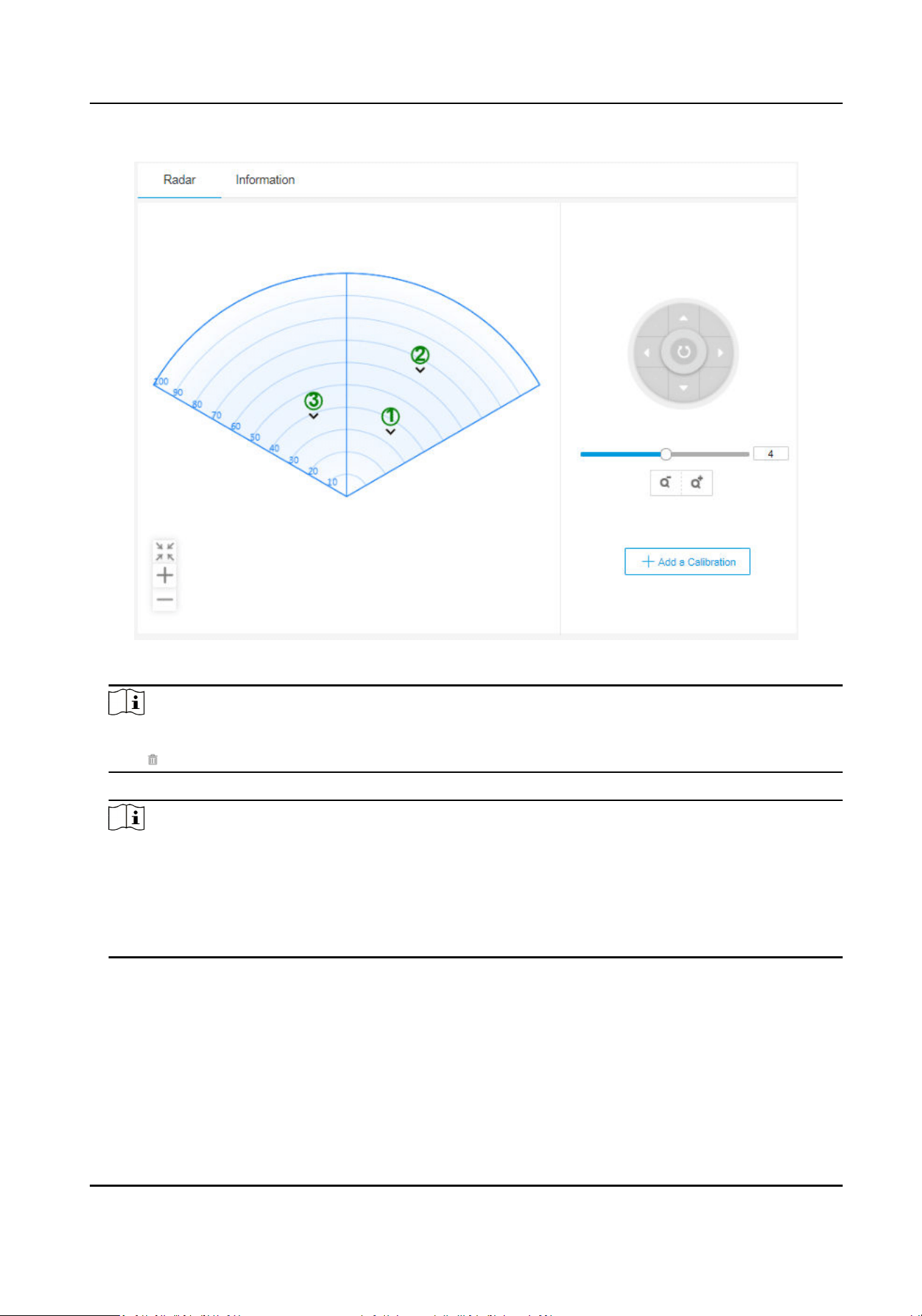
Figure 5-13 Mul-Point Calibraon
Note
If you need to delete a calibraon point, select the calibraon point in the Informaon list, and
click .
5.
Aer all calibraon points are calibrated completely, click Save.
Note
●
You can save the calibraon informaon successfully if there are 3 calibraon points,
otherwise, you cannot save it. Up to 8 points can be calibrated. It is suggested to use 3 points
to calibrate.
●
You should enable Network Poisoning System in Radar → Coordinate
Calibraon → Camera
Calibraon if the camera is installed with PTZ.
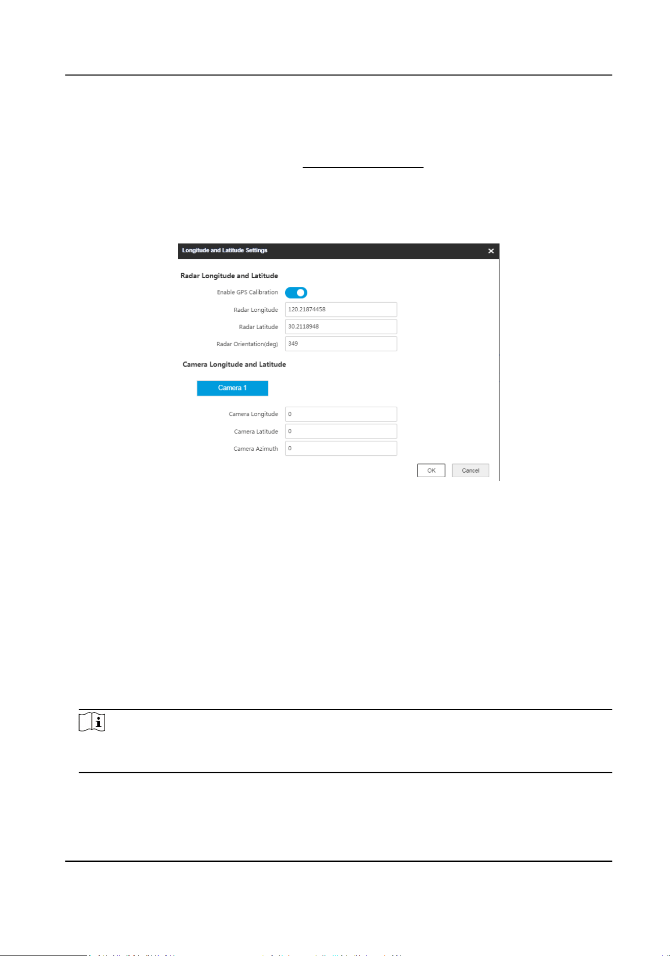
5.3.3 GPS Calibraon
GPS calibraon needs to be congured in conjuncon with one point calibraon. This calibraon
method is applicable to the scene that the camera is installed far away from the radar.
Security Radar User Manual
47
Before You Start
●
Record the latude, longitude, and orientaon of the radar installaon locaon.
●
Record the latude, longitude, and orientaon of the camera installaon locaon.
●
Complete one point
calibraon. Refer to One Point Calibraon for details.
Steps
1.
Select One Point Calibraon as the calibraon mode.
2.
Click Longitude and
Latude Sengs.
Figure 5-14 Set Longitude and Latude
3.
Slide Enable GPS Calibraon.
4.
Enter the radar longitude,
latude, and orientaon.
Radar Orientaon
The radar orientaon is the clockwise angle between the true north direcon and the radar
center line. You can place your phone on the back of the radar and use the
applicaon with
compass funcons to get this angle.
5.
Enter the longitude,
latude, and azimuth of the camera.
Camera Azimuth
Aer the zero azimuth is conrmed, you can turn the lens unl the radar is at the center cross
of the frame, at which point the P value of the camera is the azimuth of the camera.
6.
Click OK.
Note
Aer compleng the calibraon, make sure that Set before enabling trace on the calibraon
page is checked.
Security Radar User Manual
48
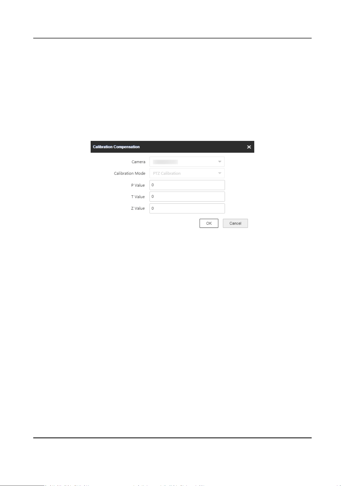
5.3.4 Calibraon Compensaon
Fine adjustment of PTZ posion of the camera.
Before You Start
The camera is calibrated.
You can use this
funcon to adjust the PTZ posion of the camera.
Steps
1.
On Coordinate Calibraon interface, click Calibraon Compensaon.
Figure 5-15 Calibraon Compensaon
2.
Select a camera.
3.
Select Calibraon Mode.
GPS
Calibraon
Compensaon for the PTZ of the camera in GPS (latude and longitude) calibraon mode.
PTZ Calibraon
Compensaon for the PTZ of the camera in single-point calibraon or mul-point calibraon
mode.
4.
Set P, T, and Z value. The entered values will be added to the original PTZ values.
5.
Click OK.
5.3.5 Learn Terrain
Terrain learning can improve the environmental adaptability of radar and linked cameras.
Before You Start
One point calibraon is completed.
Steps
1.
On Coordinate Calibraon interface, click Start to Learn Terrain.
2.
Select a track in the radar
detecon area.
Security Radar User Manual
49
3.
Click or to adjust the target. Make sure the target is in the center of the live view image.
4.
Click Complete to Learn Terrain.
Note
You can start terrain learning for mulple mes. The learning results will be cumulave.
5.
Oponal: Click Clear to Learn Terrain to reset the funcon.
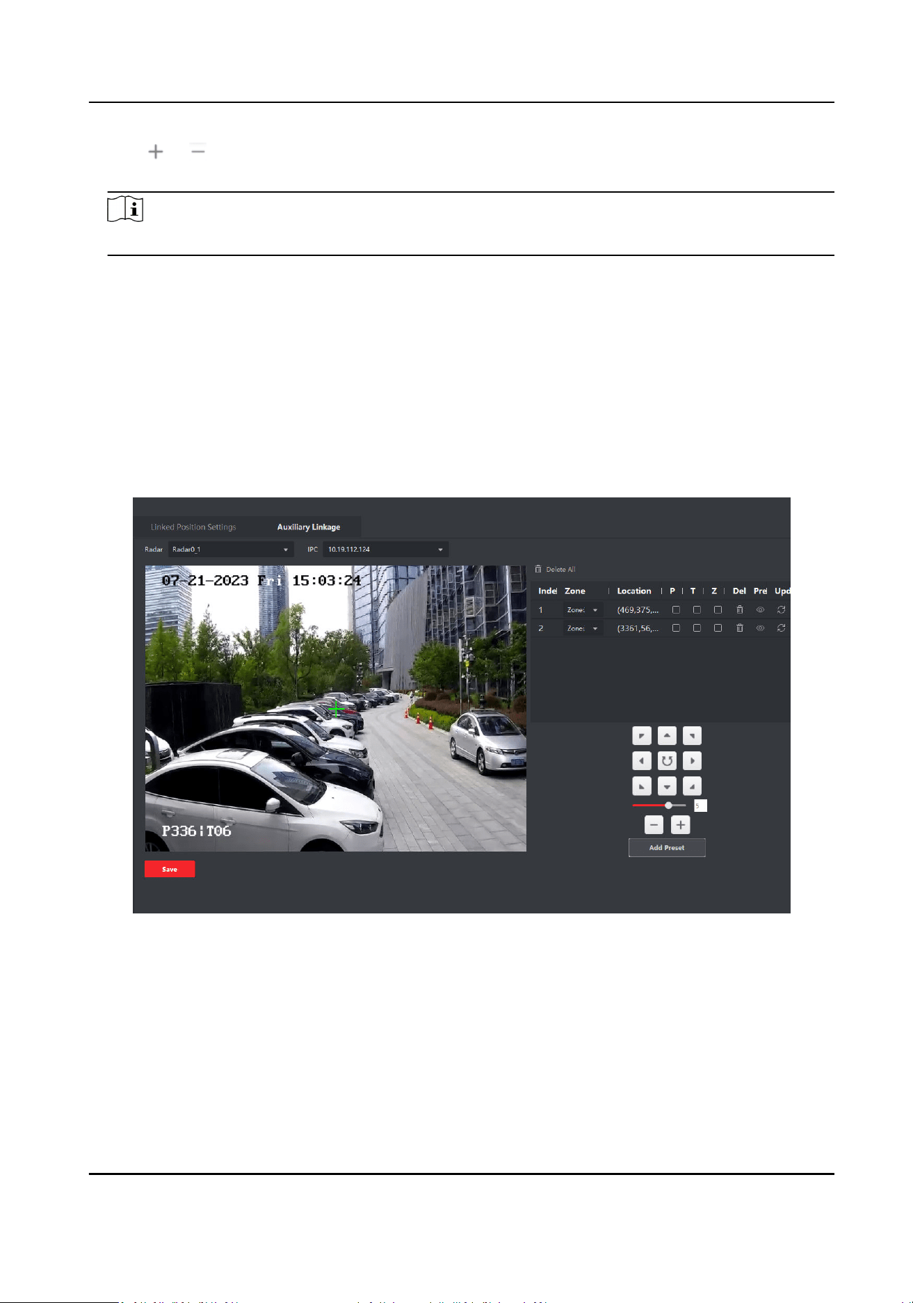
5.3.6 Auxiliary Linkage
When the environment has an impact on the target’s track during the detecon process (such as
track incoherence, track
jier, etc.), this funcon can be enabled on the basis of conguring the
zone to x the PTZ value.
Steps
1.
In the E-map page, Click Radar
Sengs → Smart Linkage Sengs → Auxiliary Linkage .
Figure 5-16 Auxiliary Linkage
2.
Click Add Preset.
3.
Select a radar and a linked camera in the drop-down list.
4.
Select a zone from the list.
5.
Use
funcon buons on the right to adjust the camera live view page center posion (cross icon
posion) to the preset. You can also click on the live view page and the live view page will
automacally adjust to the clicked center.
Security Radar User Manual
50
Operaon Descripon
Direcon-control
Buon
Adjust the camera direcon. Hold to move the camera direcon
connuously.
Rotate the camera horizontally. Hold to connuously rotate the camera
horizontally.
Bar Adjust the rotaon speed of the camera. 1 is the slowest and 7 is the
fastest.
+/- Zoom the live view page.
6.
Oponal: Edit preset.
Buon Descripon
PTZ Fix the current P/T/Z value.
Delete Delete preset.
Live View Rotate the camera to view the preset.
Update Updates the preset coordinate to the current camera coordinate.
Note
If calibraon is not possible, you can select the zone and adjust the camera posion, and x the
P, T, and Z values. When the zone triggers an alarm, the camera will automacally rotate to this
locaon.
5.4 Set Park Funcon for Linked Camera
Aer enabling the radar park mode, the main radar will control the camera to return to the set
watch point, when no target appears within 10 s in the radar
detecon area.
Before You Start
●
Add the radar to the map.
●
Link the camera to the radar, and add the camera to the client soware.
●
Calibrate the camera and enable camera tracking.
●
You need to disarm the radar before the
operaon. Click Finish in the E-map page to exit the
eding mode. Click on the radar icon and select Disarm to disarm the radar.
Note
Only camera with PTZ control supports the funcon.
Steps
1.
In the client soware, Enter the E-map page.
2.
Click Edit to enter the
eding mode. Click Radar Sengs → Set Parking Point.
Security Radar User Manual
51
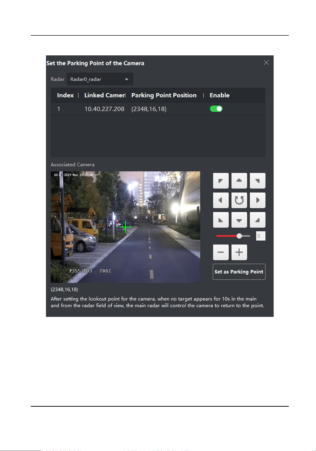
Figure 5-17 Set Camera Parking Point
3.
Select a radar in the drop-down list.
4.
Select a linked camera in the drop-down list.
5.
Use
funcon buons on the right to adjust the camera live view page center posion (cross icon
posion) to the watch point. You can also click on the screen and the live view page will
automacally adjust to the clicked center.
Operaon
Descripon
Security Radar User Manual
52
Direcon-control
Buon
Adjust the camera direcon. Hold to move the camera direcon
connuously.
Rotate the camera horizontally. Hold to connuously rotate the camera
horizontally.
Bar Adjust the rotaon speed of the camera. 1 is the slowest and 7 is the
fastest.
+/- Zoom the live view page.
6.
Click Set as Parking Point. And the slider on the right of the linked camera will be enabled.
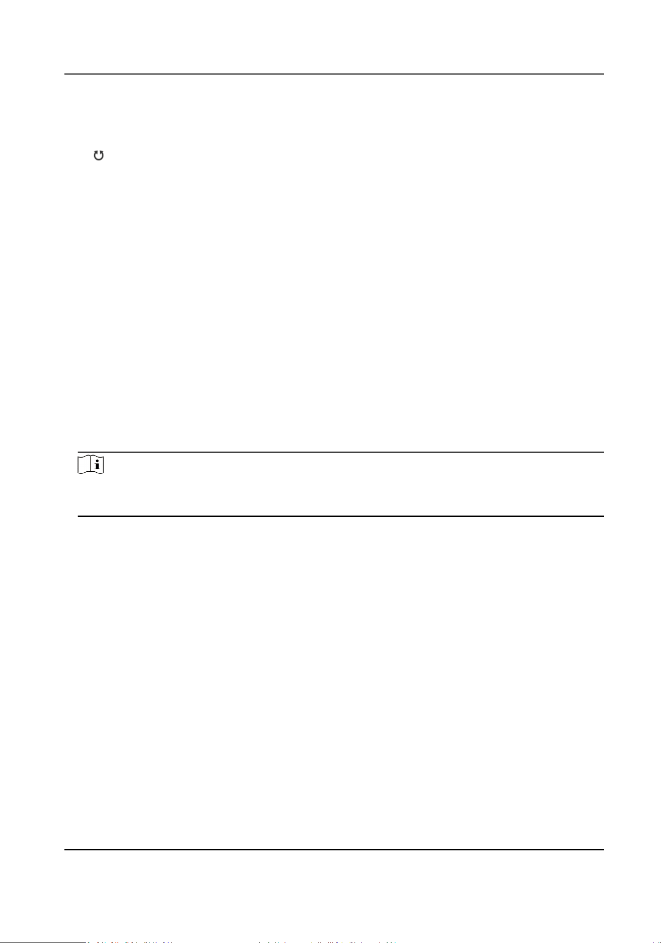
5.5 Link the Camera to the Zone
Steps
1.
In the client
soware, click E-map, click Device Management → Event Conguraon → Alarm
Event to enter the page.
2.
Select a zone in the
le list.
3.
Check an event in the right list.
4.
Click Edit Priority and you can select the event priority.
5.
Click Edit Linkage and you can check the linked
acon and camera.
6.
Enable PTZ Linkage, select Preset, Patrol or Track.
Note
●
Up to 4 cameras can be linked to the zone. Up to 50 cameras can be linked.
●
For more details, see User Manual of iVMS-4200 Client Soware.
Security Radar User Manual
53
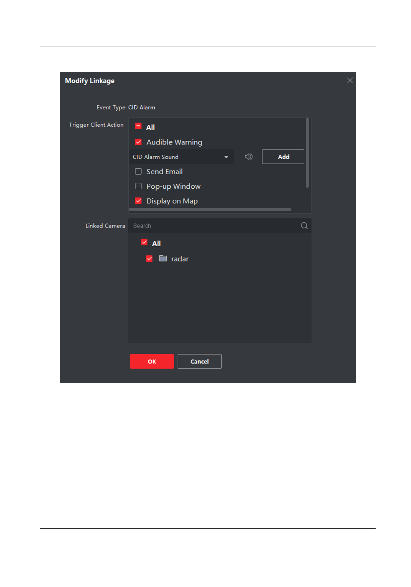
Figure 5-18 Link the Camera to the Zone
7.
Click OK.
8.
Oponal: Check events, and click Enable All or Disable All to enable or disable the events.
5.6 Set Preset Point
When an alarm is triggered, the camera automacally rotate to a preset point. This funcon can be
used without calibraon.
Security Radar User Manual
54
Before You Start
A zone or trigger line is congured.
Aer seng the preset point, the camera will automacally rotate to the preset point when the
trigger line or zone is triggered.
Steps
1.
In the client
soware, click E-map.
2.
In the upper-right corner of the page, click Radar
Conguraon → Preset Point Sengs to enter
the page.
Figure 5-19 Preset Point Sengs
Security Radar User Manual
55
3.
Slide Enable.
4.
Click Add Preset.
5.
Select a radar and a linked camera in the drop-down list.
6.
Select the trigger lines or zones in the list where you want to set a preset.
7.
Use funcon buons on the right to adjust the camera live view page center posion (cross icon
posion) to the preset. You can also click on the live view page and the live view page will
automacally adjust to the clicked center.
Operaon Descripon
Direcon-control
Buon
Adjust the camera direcon. Hold to move the camera direcon
connuously.
Rotate the camera horizontally. Hold to connuously rotate the camera
horizontally.
Bar Adjust the rotaon speed of the camera. 1 is the slowest and 7 is the
fastest.
+/- Zoom the live view page.
8.
Oponal: Edit preset.
Buon Descripon
Delete Delete preset.
Live View Rotate the camera to view the preset.
Update Updates the preset coordinate to the current camera coordinate.
9.
Click Conrm.
5.7 Pop-up Alarm
Nocaon
Before You Start
●
Link the camera to the zone.
●
Add the camera, the NVR and the radar to the client
soware.
●
You need to check Pop-up Window in the security control panel event page.
Steps
1.
In the client
soware, click E-map.
2.
Click on the boom of the page to show the alarm event list.
3.
Click
to enable alarm triggered pop-up image.
4.
When the alarm is triggered, the client soware will automacally pop up an alarm window.
Security Radar User Manual
56
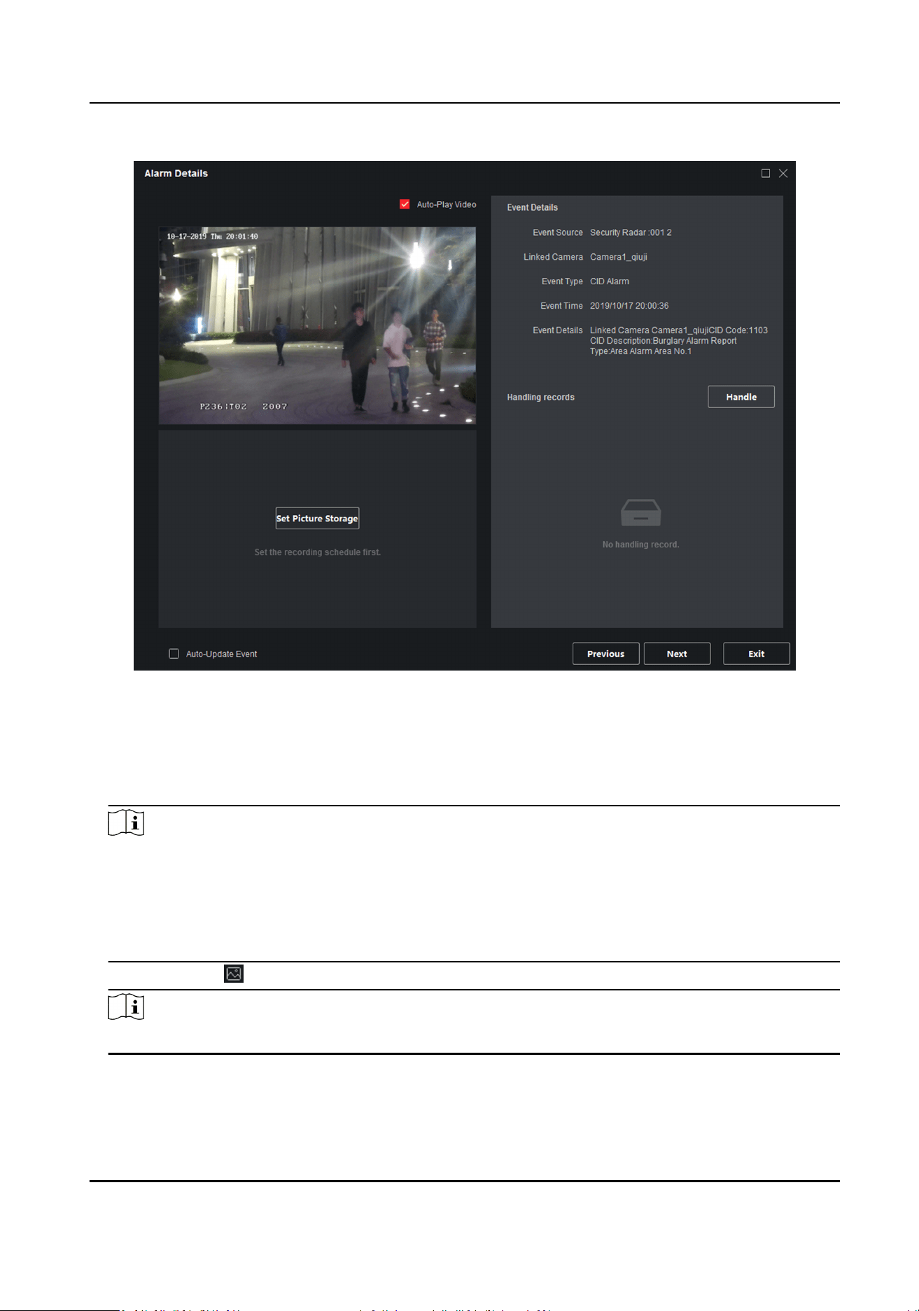
Figure 5-20 The Alarm Window
-
Check Auto-Update Event, the window will automacally switch to the new alarm video and
display the new alarm video in real me.
-
Click Previous or Next to view unread alarm messages.
-
Click Exit to exit the alarm window.
Note
●
When the alarm window is not closed and the alarm is triggered again. You need to click Next
to view the alarm triggered pop-up image.
●
When the alarm window is closed and the alarm is triggered, an alarm triggered image will be
pop up. If you do not clear the previous alarms, you can click Previousto view the alarm
triggered pop-up image before.
5.
Oponal: Click to disable the alarm triggered pop-up window.
Note
For more details, see User Manual of iVMS-4200 Client Soware.
Security Radar User Manual
57
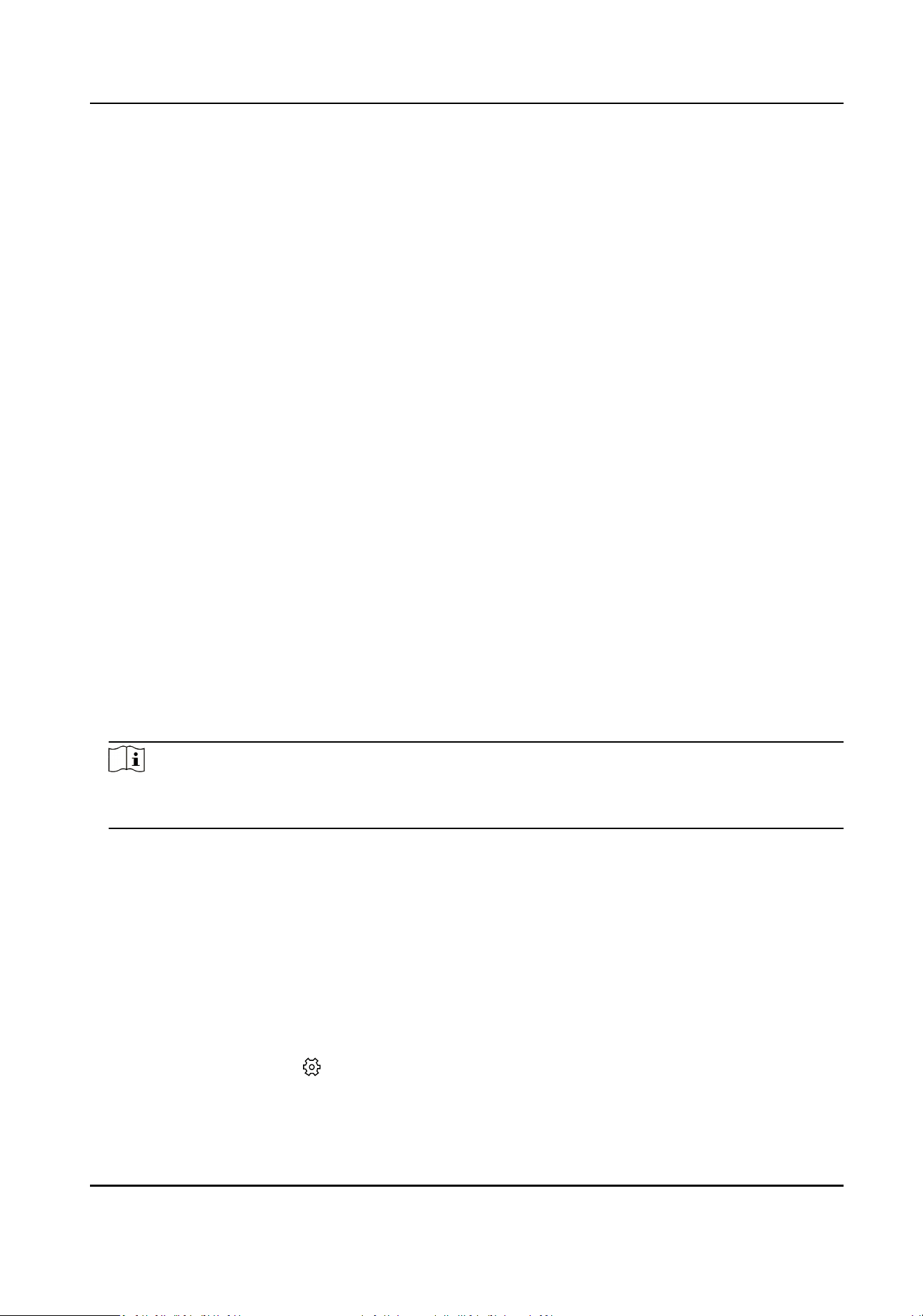
Chapter 6 Record and Storage Sengs
You can store videos by storage server or NVR. Select a kind of storage type according to actual
needs.
6.1 Set Storage Schedule via Storage Server
If NVR or SD card are not used, you can enable the storage server.
Before You Start
Make sure your computer has already installed the Storage Server that should be selected as the
component when installing client
soware. For details, see User Manual of iVMS-4200 Client.
Steps
1.
In client soware, click Storage Schedule to enter the page.
2.
Select the camera in the camera list. Enable Recording Schedule and Capture Schedule in the
storage on encoding device module.
3.
Select a template in the drop-down list (All-day Template, Weekday Template, Event Template,
etc.).
4.
Click Edit or Advanced
Sengs to set the template.
5.
Select a camera from the camera list, and select a storage server from the Storage Server drop-
down list.
6.
Enable Recording Schedule and set parameters.
7.
Check the contents need to store in the storage on PC module.
8.
Click Save.
Note
For more details, see User Manual of iVMS-4200 Client SowareUser Manual of Guarding Vision
Client Soware.
Result
Aer conguraon, the camera will start recording according to the schedule, and save the
recording videos in your PC.
6.2 Set Storage Schedule via NVR
Aer
enabling NVR, the recording videos will stored in the NVR.
Steps
1.
Select the radar and click in the client soware, or enter the IP address of the radar in the
address bar of the web browser. Go to Radar → Coordinate Calibraon → Link Camera .
Security Radar User Manual
58
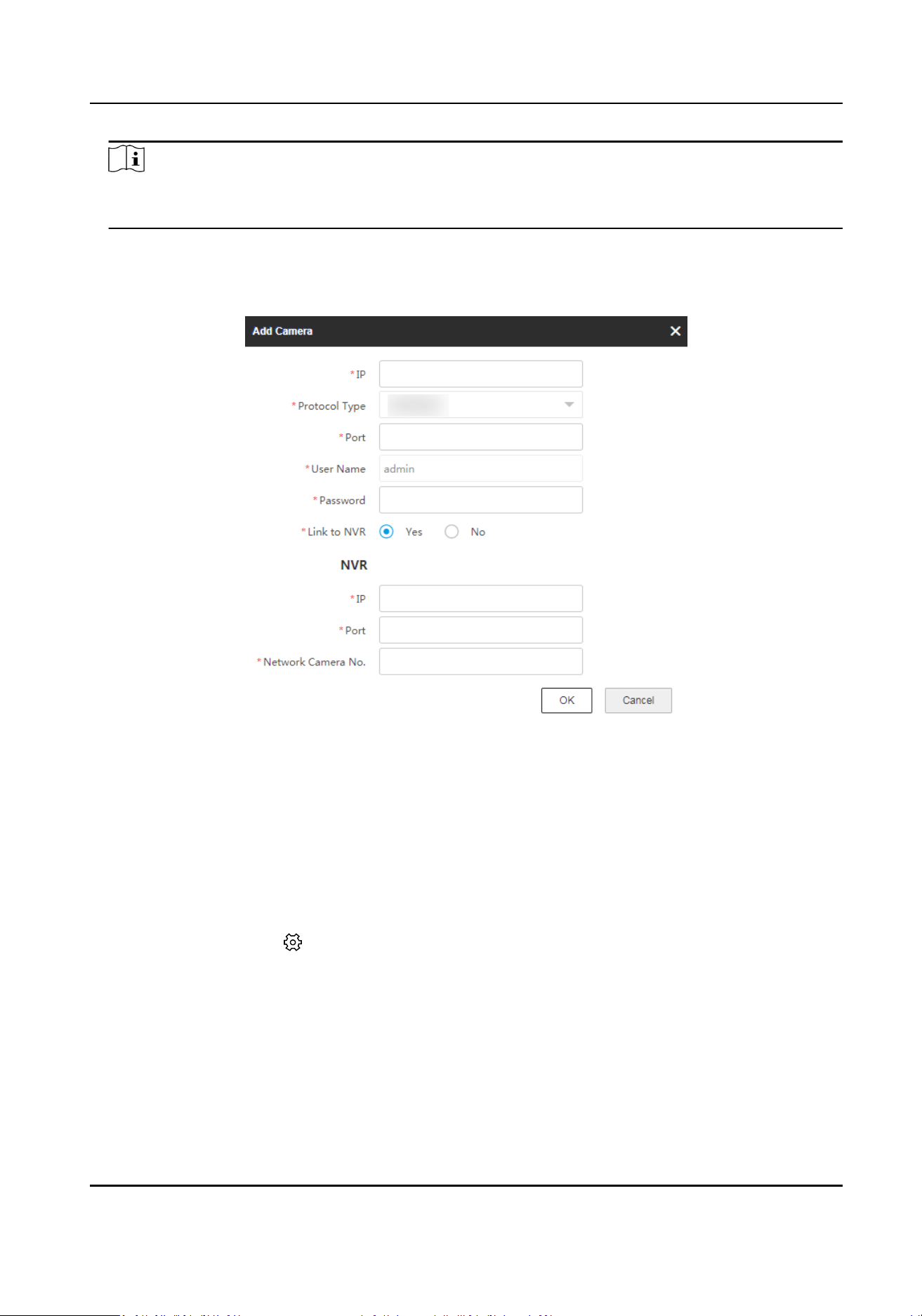
Note
The NVR channel and the radar should be in the same group, or the playback funcon cannot be
used.
2.
Add NVR.
1) Click + Add Camera in the camera list.
2) Enter the IP address, port, user name, password of the camera, and select to link to NVR.
Figure 6-1 Add NVR
3) Click OK.
Result
The recording videos of the camera will be saved in the added NVR.
6.3 Format Storage
Select the radar and click in the client soware, or enter the IP address of the radar in the
address bar of the web browser. Go to
Conguraon → Storage → Storage Management → HDD
Management .
Check an item and click Format on the upper right corner of the page to format the storage.
Security Radar User Manual
59
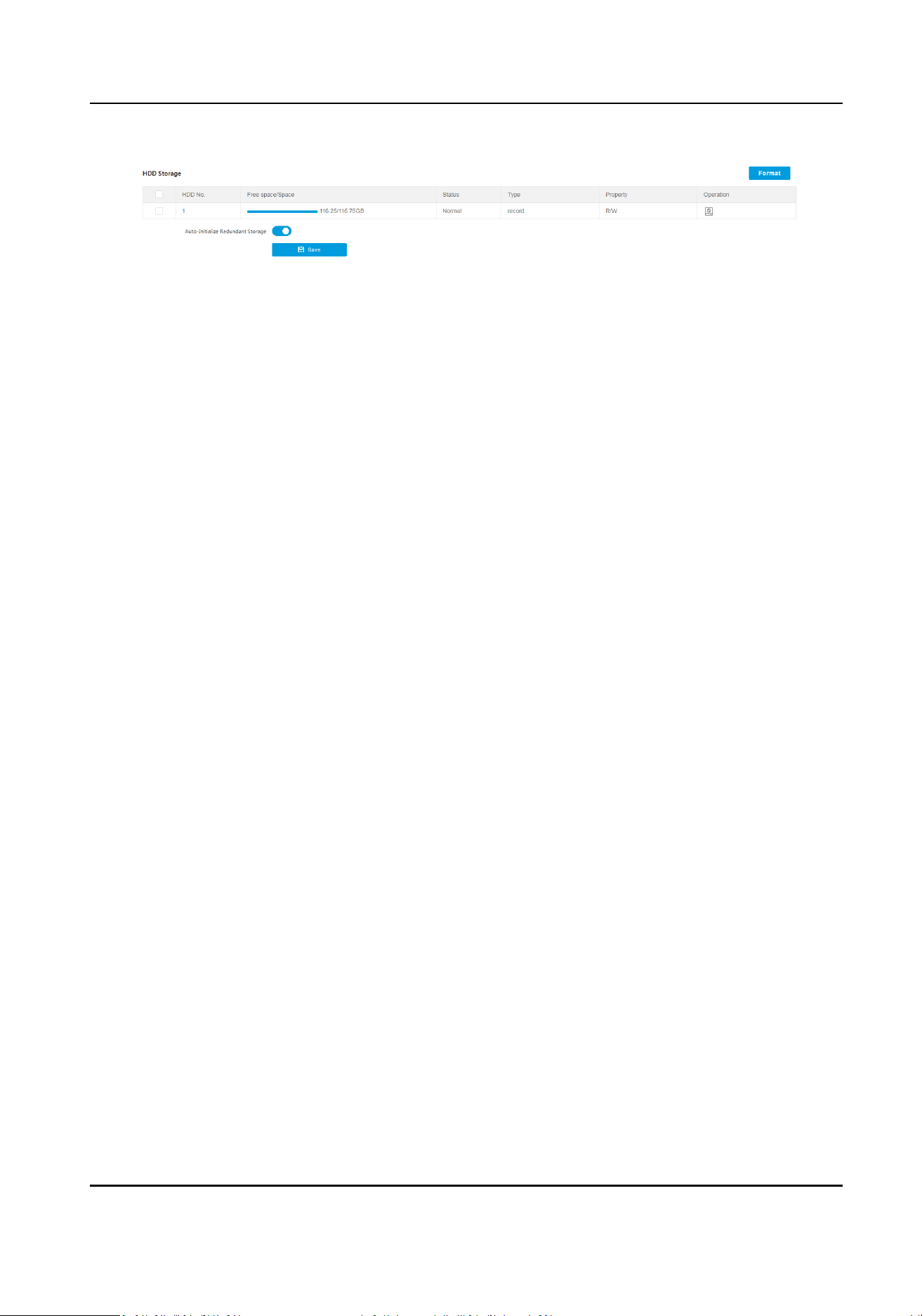
Figure 6-2 Format Storage
Auto-Inialize Redundant Storage
When
excepon occurred in the storage, it will be formaed automacally before next
reboong.
Security Radar User Manual
60
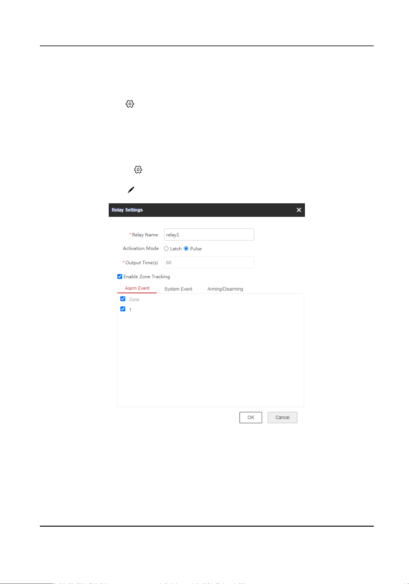
Chapter 7 Smart Rule Sengs
Select the radar and click in the client soware, or enter the IP address of the radar in the
address bar of the web browser. Click
Conguraon to enter the page.
7.1 Set Alarm Output
Steps
1.
Select the radar and click in the client soware, or enter the IP address of the radar in the
address bar of the web browser. Go to Conguraon → Alarm Module → Relay → Output .
2.
Select a relay, and click
to set the relay parameters.
Figure 7-1 Set Relay Parameters
Acvaon Mode
Latch
The alarms will output connuously.
Security Radar User Manual
61
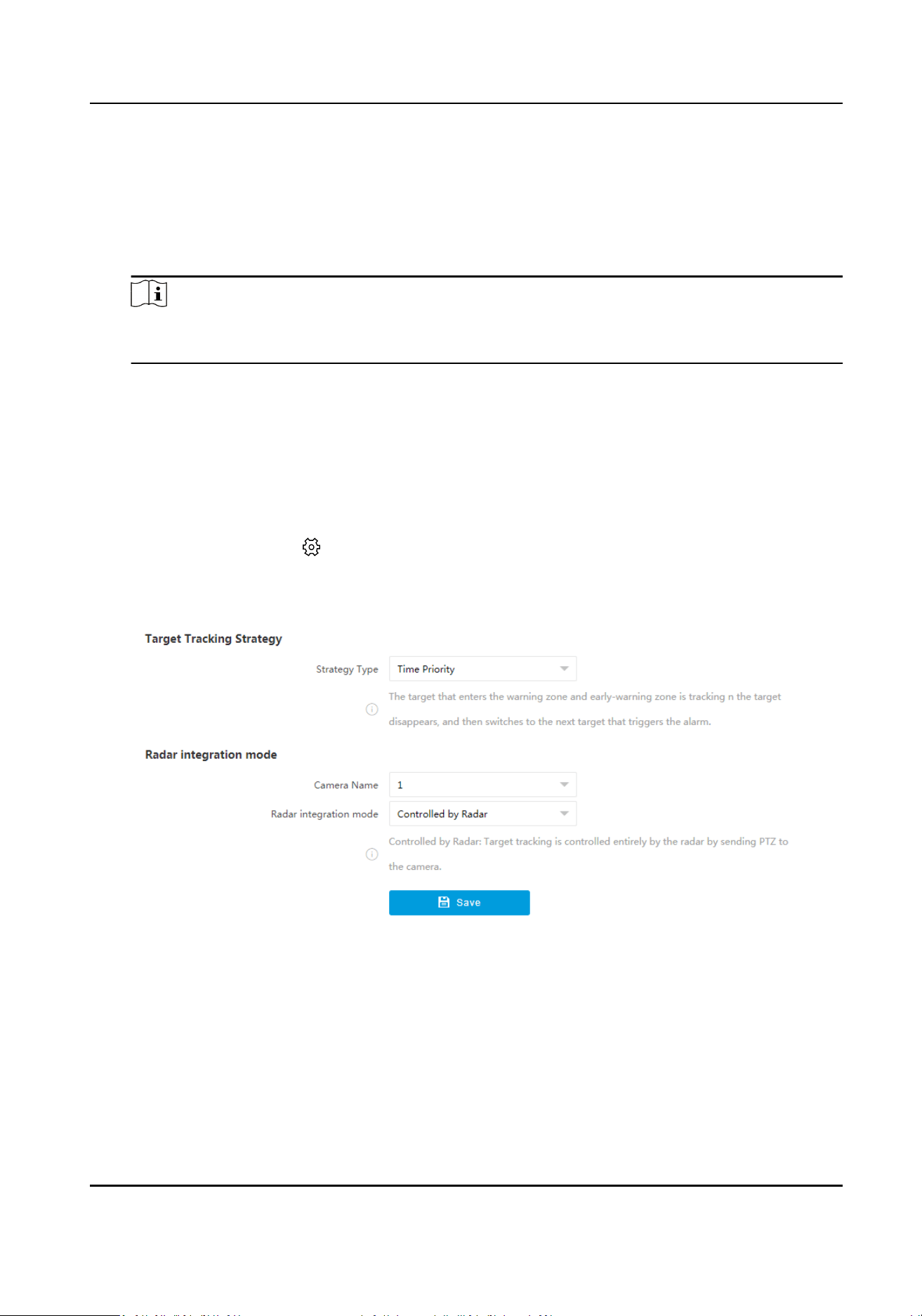
Pulse
Set Output Time, and the alarms will output for the set me.
Enable Zone Tracking
When enabled, aer the relay-linked zone is triggered by an alarm, the relay will remain open
unl the target exits the zone or the alarm is manually closed.
Note
Aer the zone tracking is enabled, if only the zone is selected in the alarm event, the relay
output me depends on the me the alarm is triggered in the zone.
3.
Set alarm output related parameters. Link the relay with alarm events, system events, and
arming/disarming operaons.
4.
Click OK.
7.2 Set Camera Linkage Trace
Steps
1.
Select the radar and click in the client soware, or enter the IP address of the radar in the
address bar of the web browser. Go to
Conguraon → Capture → Trace Sengs → Camera
Linkage Trace Sengs .
Figure 7-2 Set Camera Linkage Trace
2.
Set target tracking strategy.
Time Priority
The target that enters the warning zone and early-warning zone is being tracked unl the
target disappears, and then the next target that triggers the alarm will be tracked.
Range Priority
The target that is shortest away from the radar will be tracked.
Security Radar User Manual
62
Mul-Target Auto Switch
The target will be switched automacally when there are mulple targets in the zone. You
should set Switch Interval, and the switching order is from the smallest to the largest target
No.
Target Trigger Priority
You need to set Min. Tracking Time of New Target and Polling Time.
The latest target will be
automacally tracked and the next new target will be tracked aer
the set minimum tracking me ends. If there is no new target, the tracking target is switched
according to the polling me according to the logic of automac mul-target switching. The
switching order is from the smallest to the largest target No.
3.
Set radar
integraon mode.
Camera Name
Select the camera that linked with the radar.
Radar Integraon Mode
Controlled by Radar
Target tracking is controlled enrely by the radar by sending PTZ coordinates to the
camera.
Guided by Radar
Aer the radar detects the target, it will control the camera to the designated posion.
Then the radar will no longer control the camera tracking, and the camera will
automacally track the target in the live video.
Note
Some cameras do not support the radar guidance funcon, and a popup window will
display "The camera does not support radar guidance." during conguraon.
4.
Click Save.
7.3 Set Forced Trace
Set forced trace and the camera will track the targets in the radar detecon range forcibly.
Steps
1.
Select the radar and click in the client soware, or enter the IP address of the radar in the
address bar of the web browser. Go to
Conguraon → Capture → Trace Sengs → Forced
Trace Sengs .
Security Radar User Manual
63
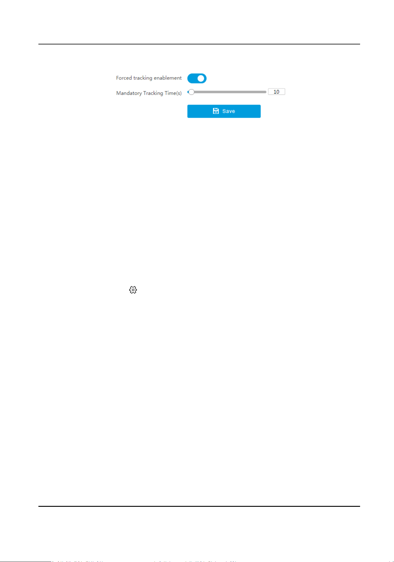
Figure 7-3 Set Forced Trace
2.
Enable Forced Tracking Enablement.
3.
Set Mandatory Tracking Time.
4.
Click Save.
7.4 Camera
Calibraon
The all-in-one mounng plate mounted radar can be calibrated according to this secon. Target
tracking correcon can be enabled for the camera enabled video content analysis.
Before You Start
●
The radar has linked with a camera.
●
The radar and the camera are installed with an all-in-one
mounng plate.
●
Enable the video content analysis before enabling target tracking correcon.
Steps
1.
Select the radar and click
in the client soware, or enter the IP address of the radar in the
address bar of the web browser. Go to Radar → Coordinate Calibraon → Camera Calibraon .
Security Radar User Manual
64
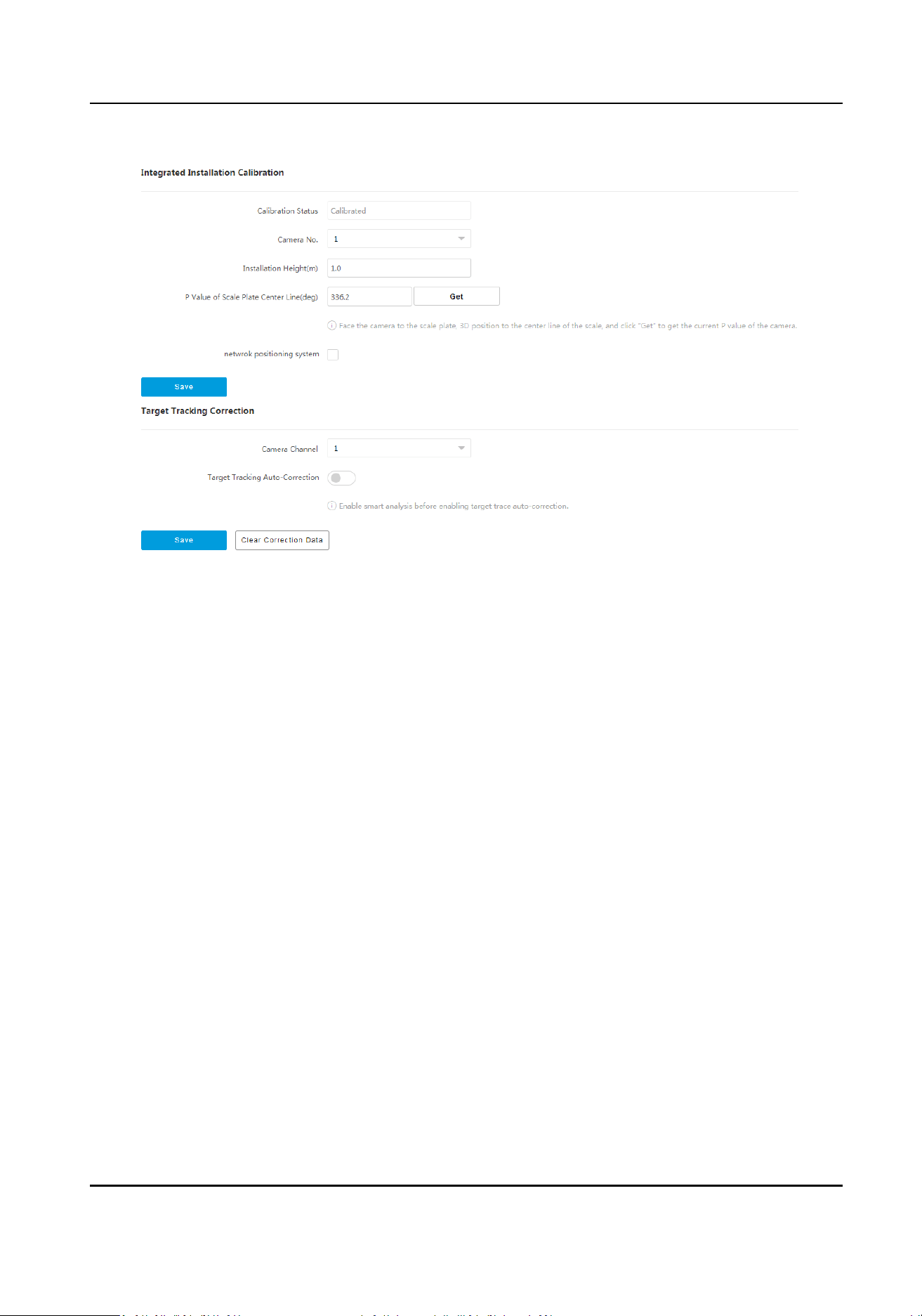
Figure 7-4 Camera Calibraon
2.
Set integrated installaon calibraon.
1) Select Camera No.
2) Enter
Installaon Height. It is the vercal height from the camera to the detecon surface.
3) Face the camera to the ruler, enlarge the image, enable 3D posioning, and click the center
line of the ruler, and the center of the live view image will be
automacally adjusted. Click Get
to get the P Value of Scale Plate Center Line.
4)
Oponal: For cameras installed with PTZ, check Network Posioning System.
5) Click Save.
3.
Set target tracking
correcon.
1) Select Camera Channel which has been enabled video content analysis.
2) Enable Target Tracking Auto-Correcon, and set the parameters.
Target Tracking
Auto-Correcon
When enabled, the target will be in the best posion in the live view image. The camera
will automacally adjust the lens to center the target. When the funcon is enabled, the
device will
connue to adapt to the terrain in the live view image according to each
judgment to achieve the best eect.
Sensivity Auto-Correcon
The higher the sensivity, the faster the adjustment, but the less the accuracy.
Save Auto-Correcon Data
Disabled by default. When enabled, the auto-corrected debug data and video data will be
packaged and stored to the SD card.
3) Click Save.
Security Radar User Manual
65
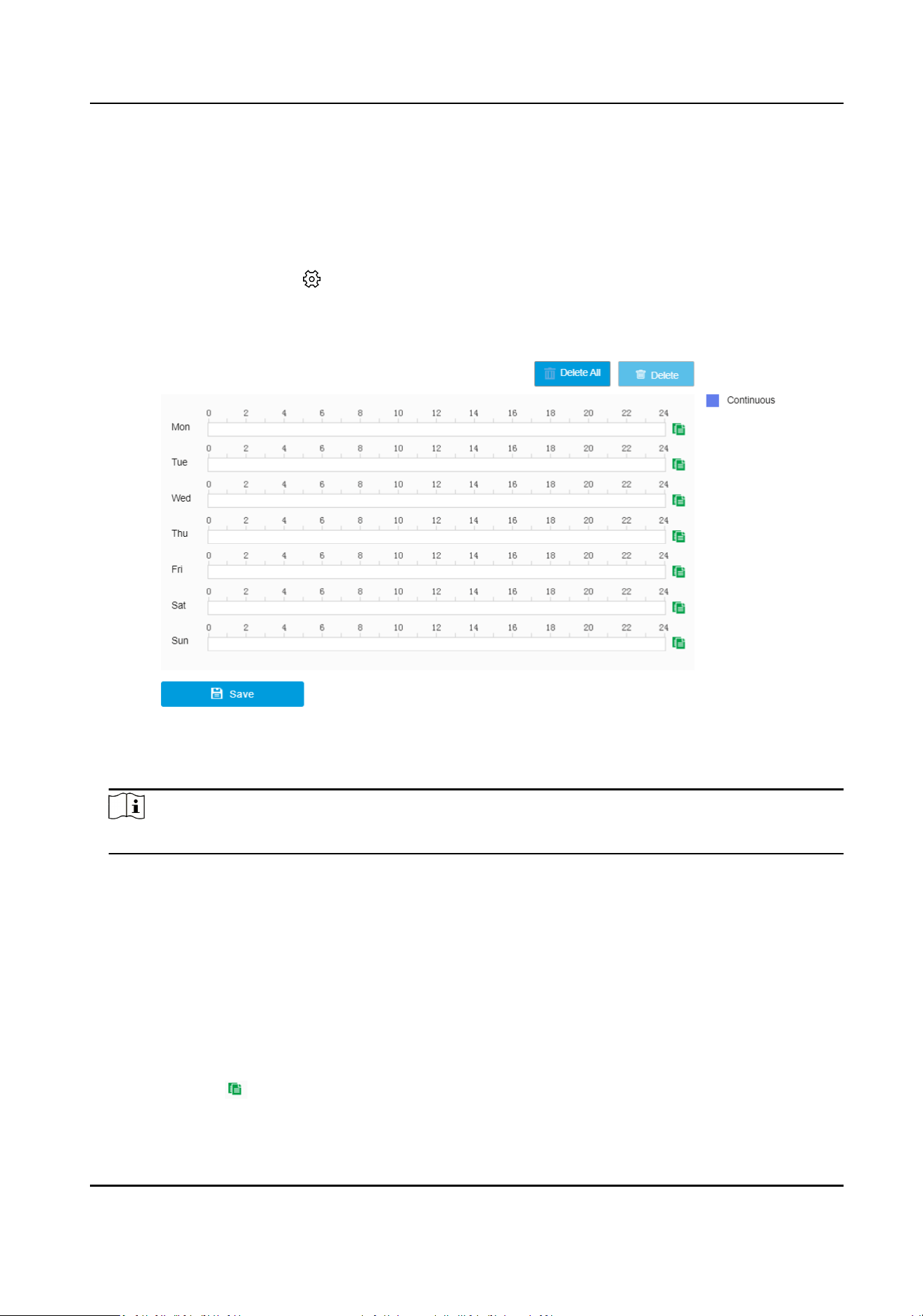
4) Oponal: Click Clear Correcon Data to clear the target tracking correcon data.
7.5 Set Arming/Disarming Schedule
Steps
1.
Select the radar and click in the client soware, or enter the IP address of the radar in the
address bar of the web browser. Go to Conguraon → Capture → Arming/Disarming Schedule
→ Arming/Disarming Schedule .
Figure 7-5 Set Arming/Disarming Schedule
2.
Drag the cursor on the me bar to set an arming/disarming me.
Note
Up to 2 me periods can be set on a me bar.
3.
Adjust the arming/disarming me.
-
Click a set arming/disarming period and enter the start me and end me in the pop-up
window.
-
Drag two ends of the set arming/disarming period bar to adjust the length.
-
Drag the whole set arming/disarming period bar and relocate it.
4.
Oponal: Delete arming/disarming periods.
-
Click a set arming/disarming period and click Delete in the pop-up window.
-
Click a set arming/disarming period and click Delete on the arming/disarming schedule
interface.
-
Click Delete All to delete all the arming/disarming schedule.
5.
Oponal: Click to copy the sengs to other days.
6.
ClickSaveto save.
Security Radar User Manual
66
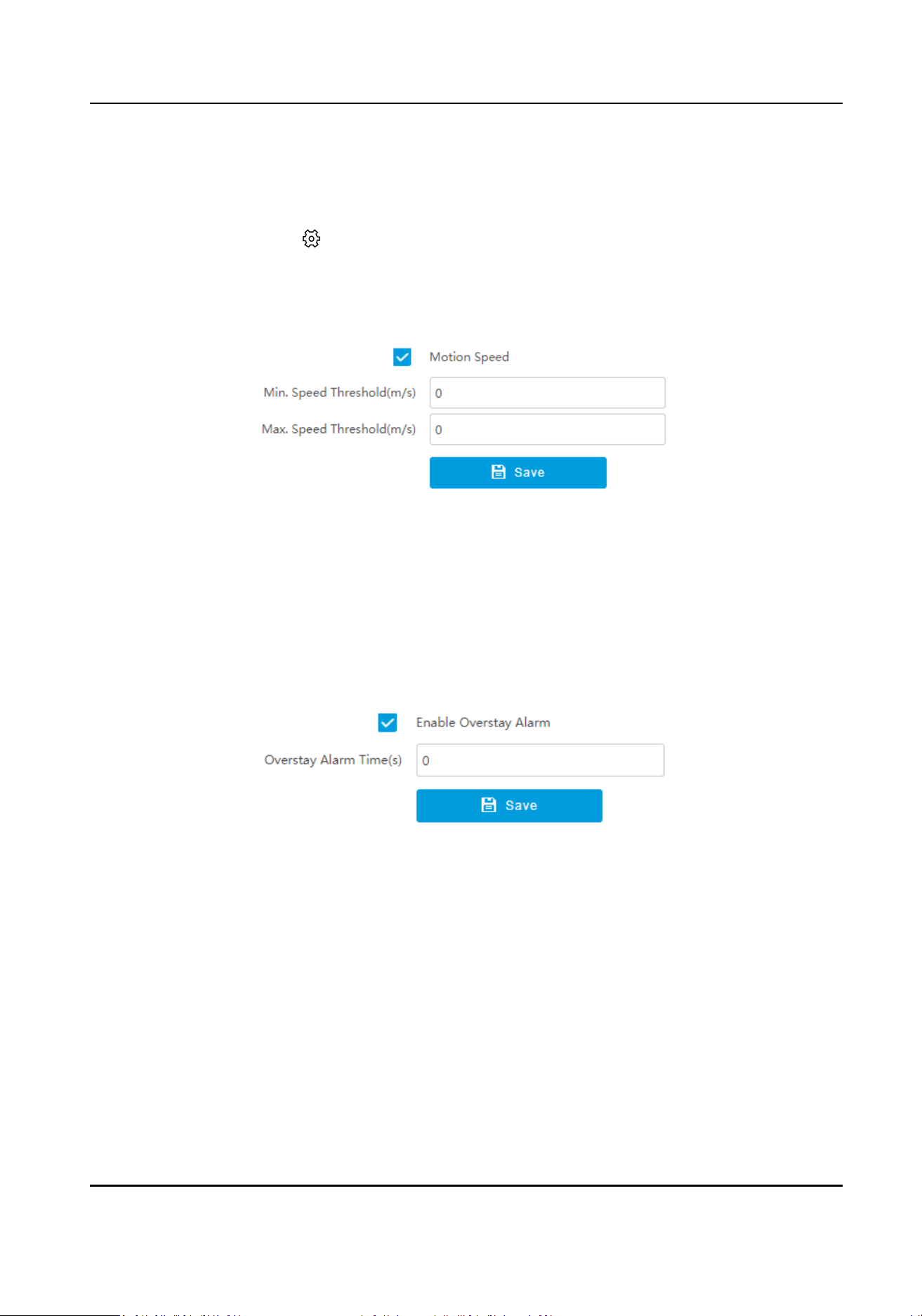
7.6 Set Alarm
Steps
1.
Select the radar and click in the client soware, or enter the IP address of the radar in the
address bar of the web browser. Go to Conguraon → Alarm Module → Alarm Sengs .
2.
Set
moon speed.
1) Click Moon Speed.
Figure 7-6 Set Moon Speed
2) Enable Moon Speed.
3) Set Min. Speed Threshold and Max. Speed Threshold.
Only the target that moves in set speed threshold will trigger the alarm.
4) Click Save.
3.
Set overstay alarm.
1) Click Overstay Alarm.
Figure 7-7 Set Overstay Alarm
2) Check Enable Overstay Alarm.
3) Set Overstay Alarm Time.
Targets that stay longer than the overstay
me will trigger an alarm.
4) Click Save.
Security Radar User Manual
67
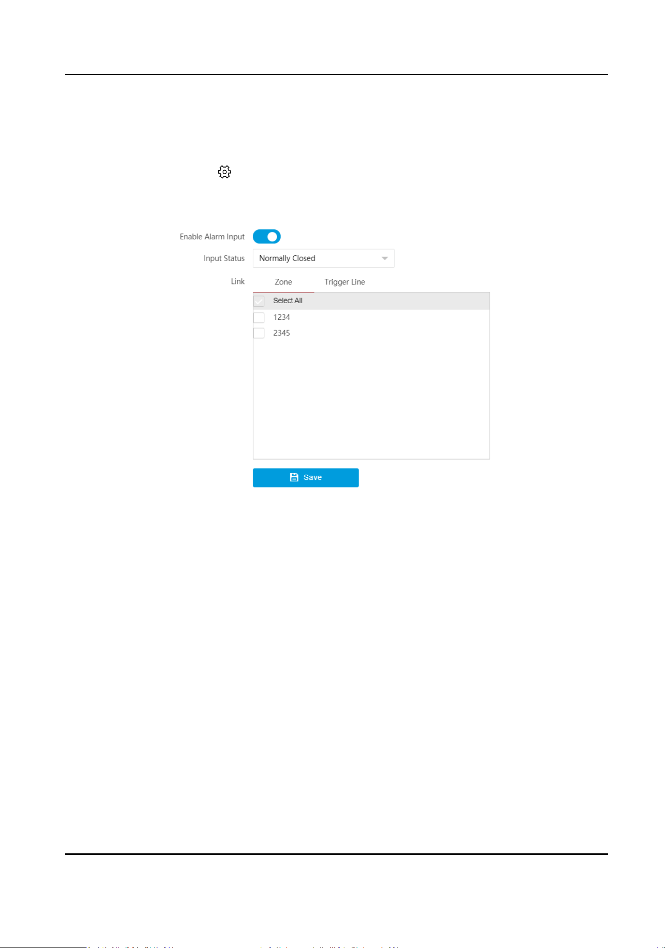
7.7 Set Alarm Input
Steps
1.
Select the radar and click in the client soware, or enter the IP address of the radar in the
address bar of the web browser. Go to Conguraon → Alarm Module → Alarm Input Sengs
→ Alarm Input Sengs .
Figure 7-8 Set Alarm Input
2.
Enable alarm input.
3.
Select Input Status.
4.
Select zones and trigger lines to be linked.
When there is an alarm input, the linked zones and trigger lines will trigger an alarm.
5.
Click Save.
7.8 Video Content Analysis
Smart analysis of the detecon targets.
Before You Start
●
Link and calibrate the camera (speed domes or network
posioning system). If the camera is a
box camera, calibraon is not required.
●
Link the camera to the zone.
●
Make sure the camera supports this
funcon.
Aer video analysis is enabled, the similarity will be displayed when the target is detected. (The
corresponding
opon should be selected.)
Security Radar User Manual
68
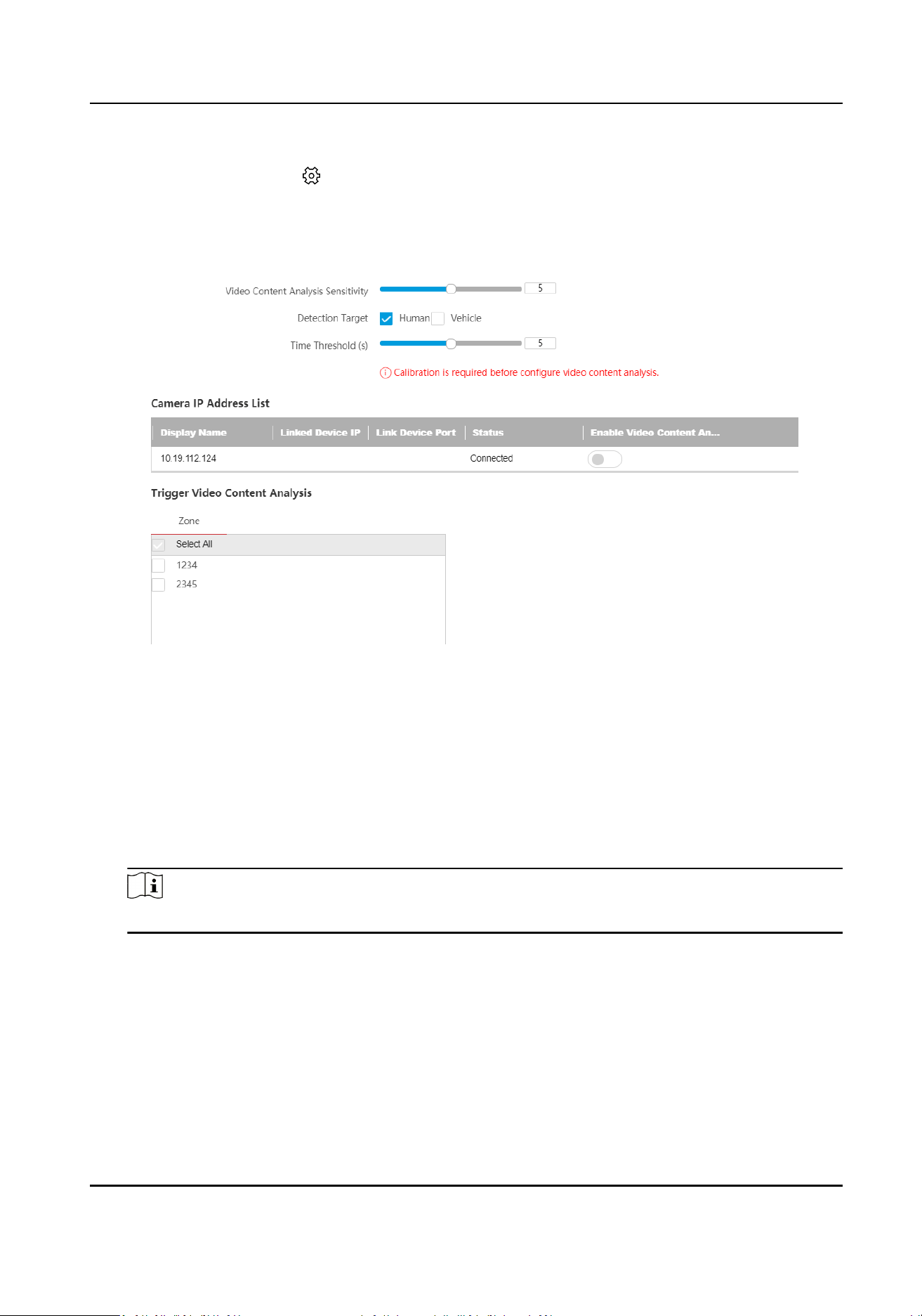
Steps
1.
Select the radar and click in the client soware, or enter the IP address of the radar in the
address bar of the web browser. Go to Conguraon → Capture → Video Content Analysis .
2.
Set video content analysis parameters.
1) Click Video Content Analysis.
Figure 7-9 Video Content Analysis
2) Set Video Content Analysis Sensivity and Time Threshold.
Video Content Analysis
The
sensivity of detecng targets.
Time Threshold
Radar analysis me, aer which the target will be judged as others.
3) Select Detecon Target.
4) In the camera IP address list, enable the device that needs to use video content analysis.
Note
Only one video content analysis channel is supported.
5) Check the zones that will trigger the video content analysis.
6) ClickSave.
3.
Set smart analysis me schedule.
1) Click Smart Analysis Time Schedule.
2) Set the
me schedule. The conguraon method is the same with that of the arming/
disarming schedule.
Security Radar User Manual
69
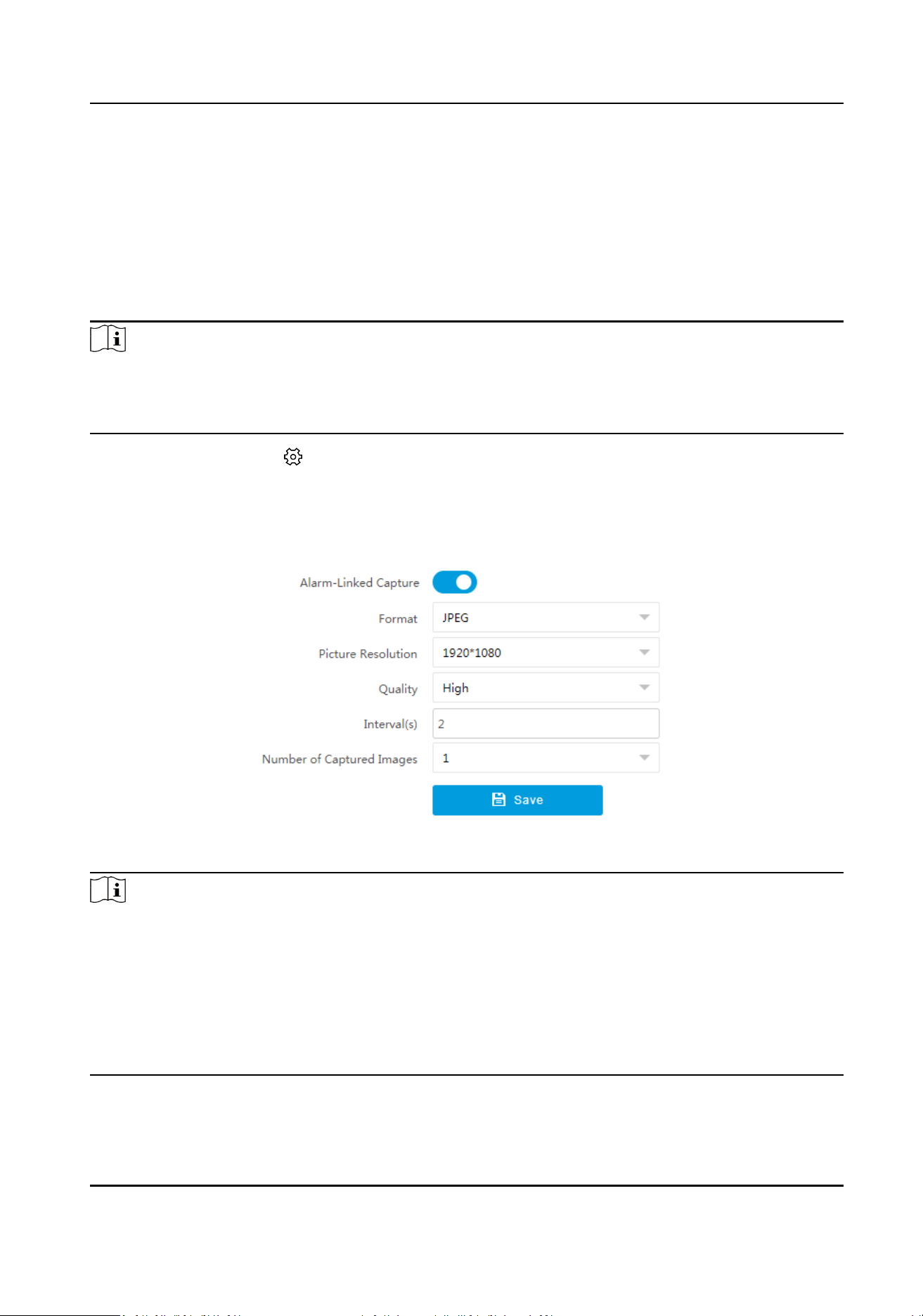
Outside the congured video content analysis me schedule, alarm will be triggered according
to the logic of disabled video content analysis, that is, all targets that trigger the zones will be
alarmed.
7.9 Set Capture Parameters
Capture pictures when an alarm is triggered.
Note
●
Calibrate the radar rst.
●
Go to Conguraon → Capture → Trace Sengs → Camera Linkage Trace Sengs to set the
target tracking strategy as Target Trigger Priority.
Select the radar and click in the client soware, or enter the IP address of the radar in the
address bar of the web browser. Go to
Conguraon → Capture → Capture Sengs → Capture
Sengs . Enable Alarm-Linked Capture.
Set captured picture format,
resoluon, quality, interval, and number.
Figure 7-10 Set Capture Parameters
Note
●
When you want to capture mulple pictures for a single target, you can set Interval for every
two pictures.
●
Total Capture Time = Interval × (Number of Captured Images - 1). The total capture me is
recommended to be less than the set Min. Tracking Time of New Target in
Conguraon →
Capture → Trace
Sengs → Camera Linkage Trace Sengs . Otherwise when the radar switches
targets, if pictures are not completely captured, the capture will be stopped and only the
captured pictures will be uploaded.
Security Radar User Manual
70
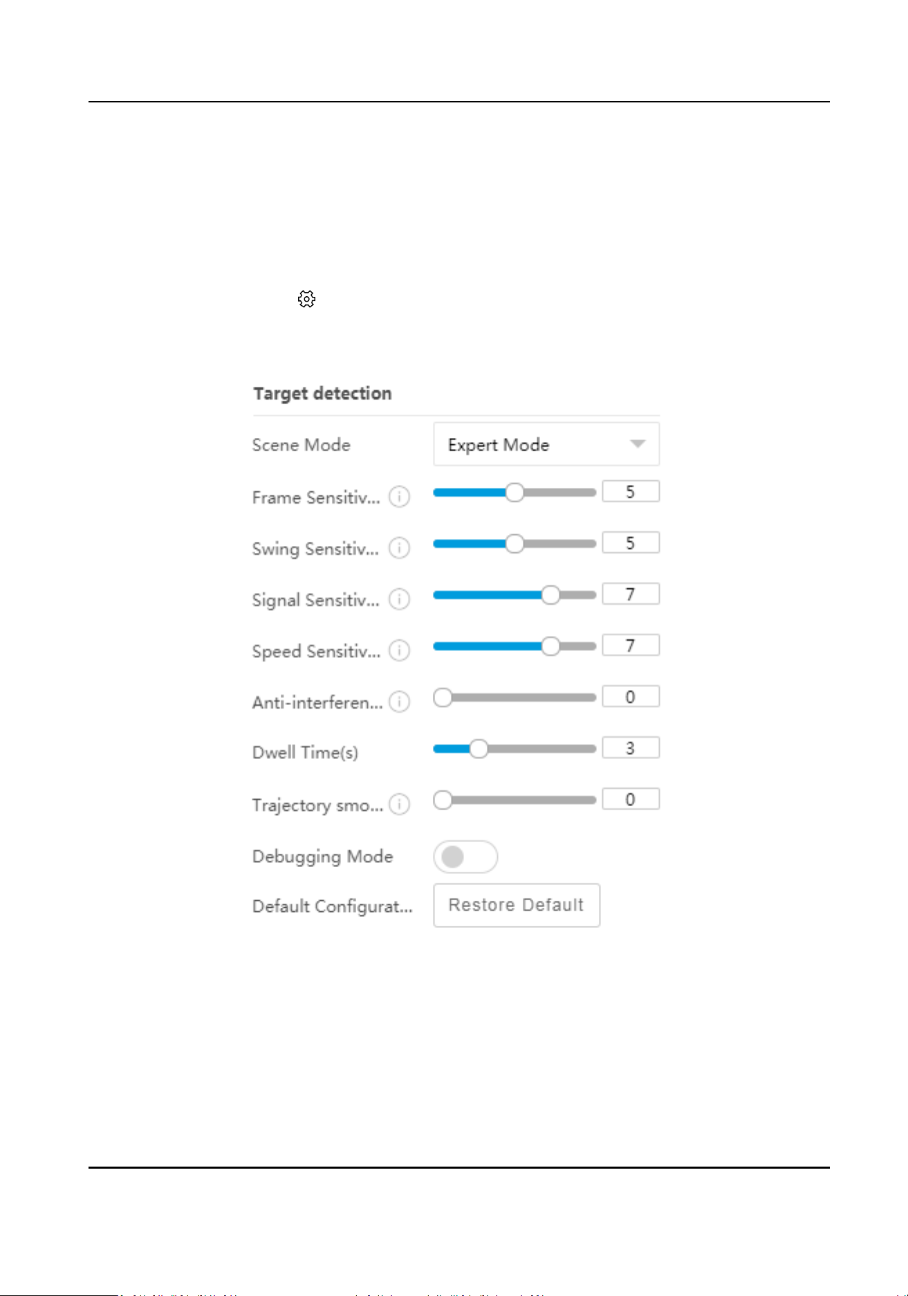
Chapter 8 Set Radar Advanced Funcon
8.1 Set Target Detecon
Steps
1.
Select the radar and click in the client soware, or enter the IP address of the radar in the
address bar of the web browser. Go to Radar → Parameter Cong → Radar Sengs → Target
Detecon .
Figure 8-1 Set Target Detecon
2.
Select Scene Mode according to the actual scene.
Expert Mode
Frame Sensivity
Security Radar User Manual
71

It represents for the required min. frames for generang target ID. The higher the
sensivity is, the easier the targets can be detected.
Swing Sensivity
It represents for the moon characteriscs of the targets. The higher the sensivity is, the
beer the tangenal and low-speed targets can be detected. The lower the sensivity is,
the beer the ashing traces can be ltered, and the later the tangenal and low-speed
targets can be detected.
Signal
Sensivity
It represents for the cfar threshold. The higher the sensivity is, the lower the cfar
threshold is, and the easier the
low-consumpon targets can be detected.
Speed Sensivity
It represents for the detected zero-speed zone size. The higher the sensivity, the smaller
the zero-speed zone. The targets in the zero-speed zone will be ltered based on swing
sensivity, and the targets outside the zero-speed zone will be detected directly. The lower
the
sensivity is, the larger the zero-speed zone will be, and the later the tangenal and
low-speed targets can be detected.
Suggeson: Set 8 to 9 for empty scenes. Set 7 for low-speed targets such as a small
number of shrubs. Set 5 to 6 for large areas of trees. Set 1 to 4 for river scenes and high
wind scenes.
An-interference Sensivity
It represents for the an-interference ability of algorithm. The higher the sensivity is, the
stronger the
an-interference ability will be. But it will increase computaon and the CPU
usage of algorithm.
Dwell Time
If the target stands sll aer being detected, it will disappear aer the set dwell me.
Trajectory Smoothness Sensivity
It represents for the smooth degree of the trace. The higher the sensivity, the smoother
the trace.
Open Mode
It is applicable to the scenes where there are no large objects in the radar
detecon area.
Shrub Mode
It is applicable to the scenes where there are shrubs and other objects that are likely to swing
in the radar detecon area. The shrub mode can also be used to decrease the interference of
rainstorm.
Common Mode
It is applicable to the common scenes.
Railway Mode
Security Radar User Manual
72
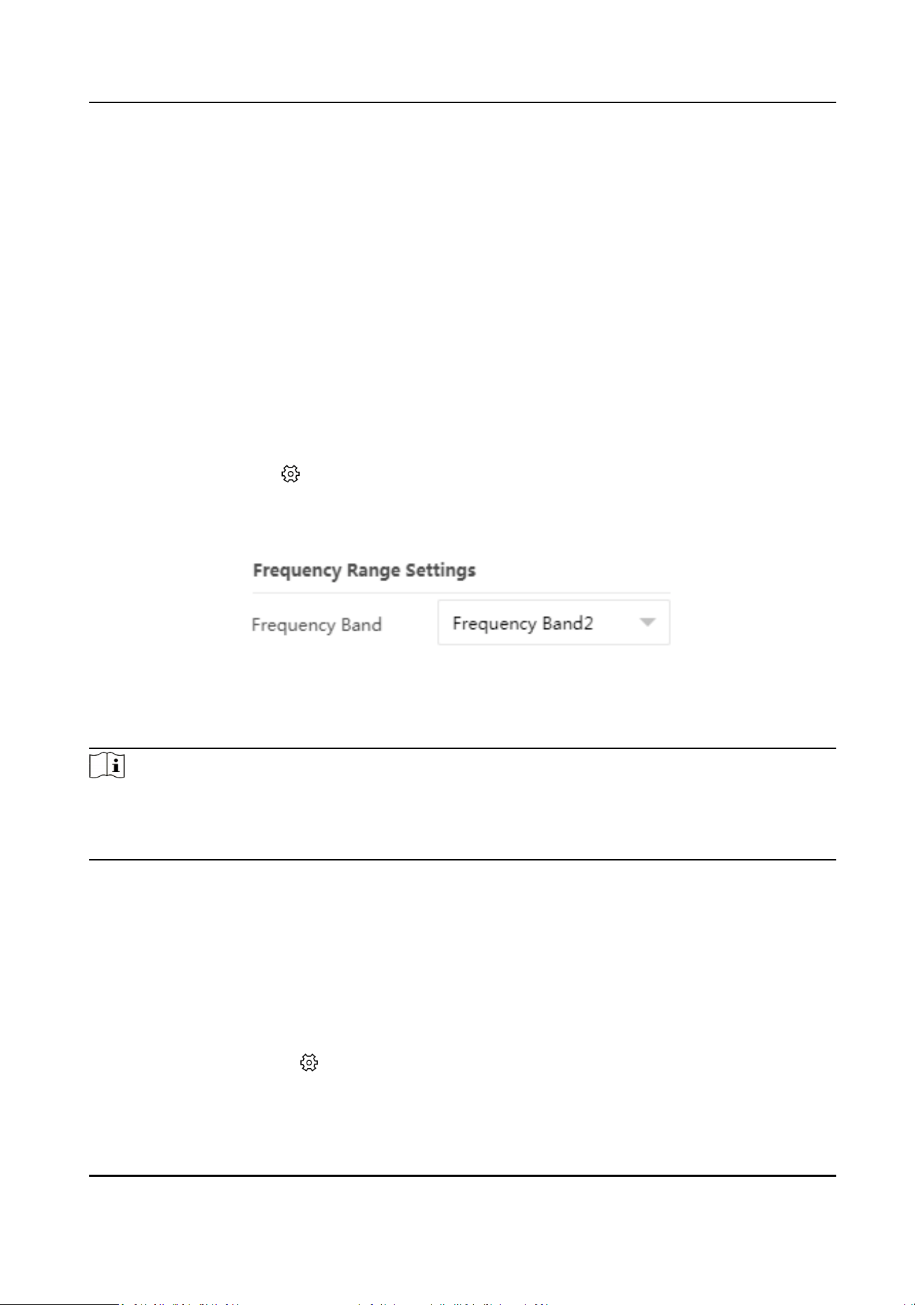
It is applicable to the railway scenes in which radars are constructed around the railway to
lter the trains.
Jail Mode
It is applicable to the jail scenes with the width of 5 m to detect persons.
3.
Enable Debugging Mode.
Aer it is enabled, the number of targets detected by the radar, target speed, posion, and
other
informaon will be superimposed into the stream, which is mainly used for device
debugging and maintenance.
4.
Click Set to save the
sengs.
5.
Oponal: Click Restore Default to restore the sengs to the default.
8.2 Set Frequency Range
Select the radar and click in the client soware, or enter the IP address of the radar in the
address bar of the web browser. Go to Radar → Parameter Cong → Radar Sengs → Frequency
Range
Sengs .
Figure 8-2 Set Frequency Range
The radar supports mulple frequency bands. You can select one according to the actual needs.
Click Set to save the
sengs.
Note
●
When mulple radars cover the same area, co-frequency interference can be reduced by seng
dierent frequency bands.
●
Try to avoid overlapping radar detecon areas.
8.3 Set Panorama Tracking
You can arrange mulple radars for linkage detecon and set the main-sub radar relaonship.
Before You Start
There are at least 2 online radars.
Steps
1.
Select the radar and click in the client soware, or enter the IP address of the radar in the
address bar of the web browser. Go to Radar → Parameter
Cong → Radar Sengs →
Panorama Tracking Sengs to enter the page.
Security Radar User Manual
73
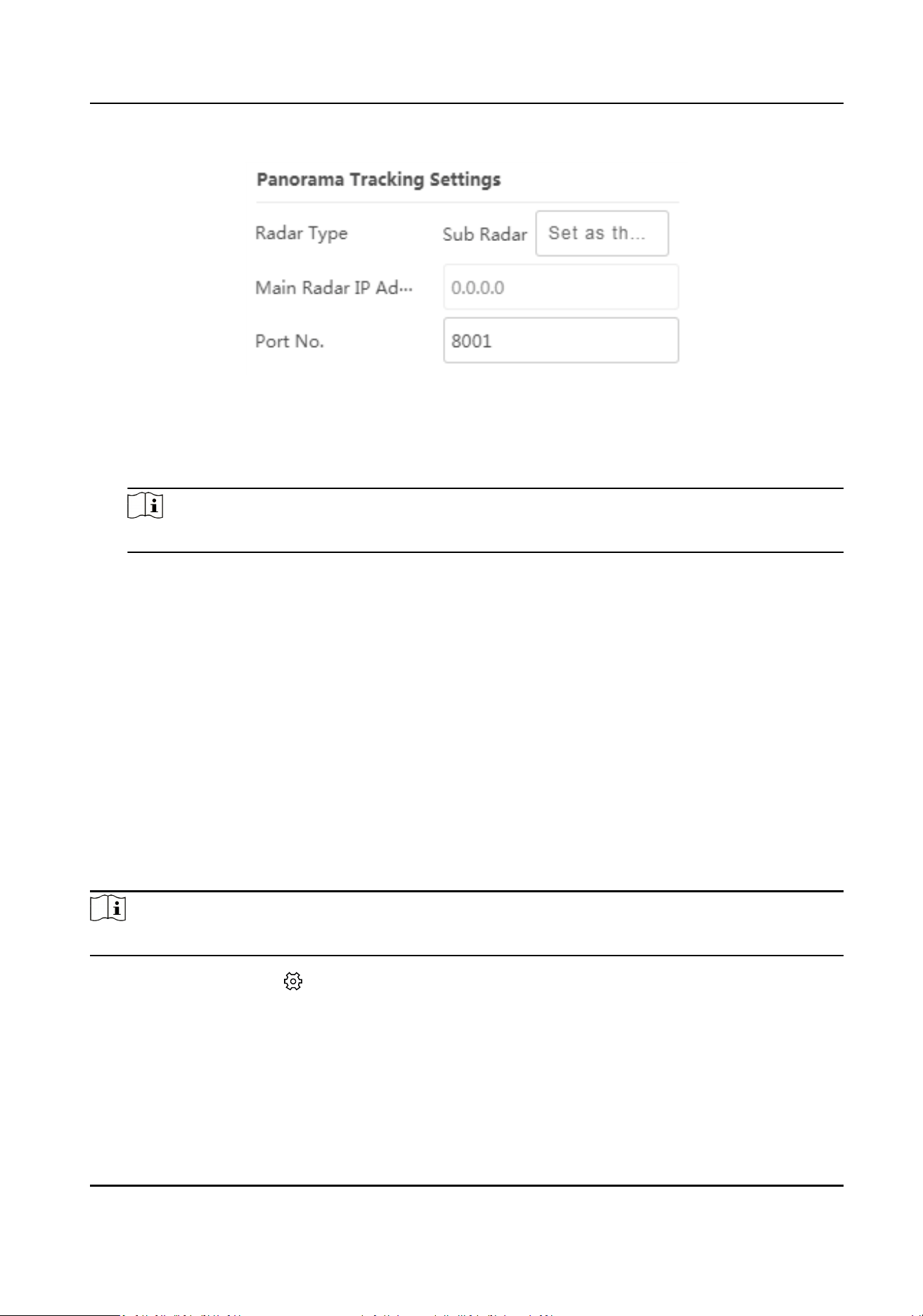
Figure 8-3 Set Panorama Tracking
2.
Set the radar type and parameters.
-
If the current radar is set as a main radar, you can add, edit, delete the sub-radar, and set the
sub-radar priority.
Note
The port No. set for the sub-radar should be the same as that of the main radar.
-
If the current radar is set as a sub-radar, you need to set the main radar IP address and port
No.
3.
Click Set to save the
sengs.
Result
When the sub-radar detects the target and triggers the alarm, the target informaon to be tracked
will be sent to the main radar, and the main radar will arrange linked cameras to track the target
according to the set radar priority.
8.4 Set Array
Set the communicaon parameters between the radar module and the main board. Aer the
communicaon parameters are congured, the radar module and the main board can
communicate properly.
Note
Some models support reading the parameters only.
Select the radar and click in the client soware, or enter the IP address of the radar in the
address bar of the web browser. Go to Radar → Parameter
Cong → Radar Sengs → Advanced
Sengs .
Security Radar User Manual
74
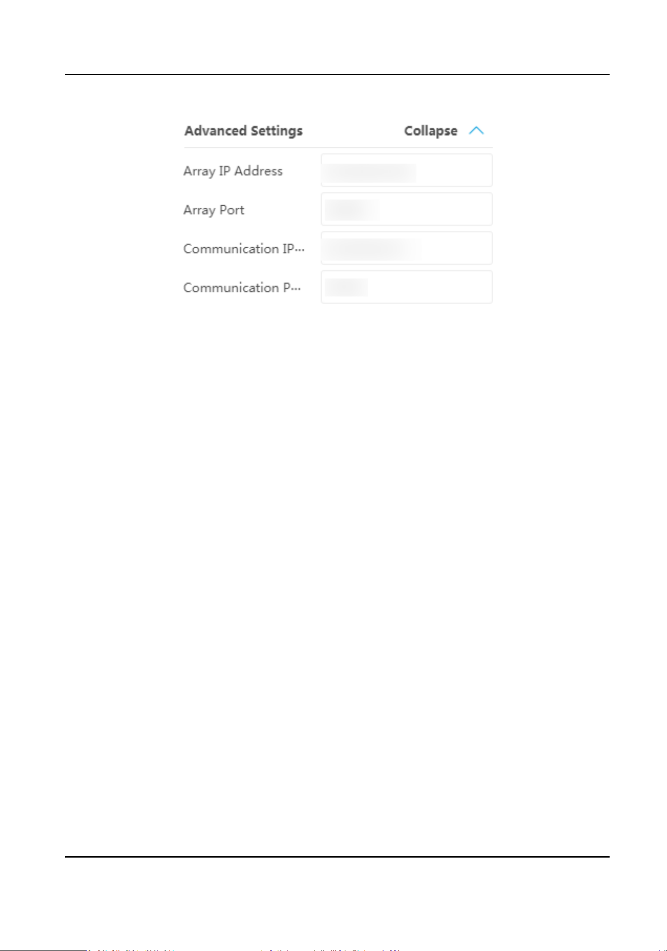
Figure 8-4 Set Array
Enter Array IP Address, Array Port, Communicaon IP Address, and Communicaon Port. Click
Set to save the
sengs.
Security Radar User Manual
75
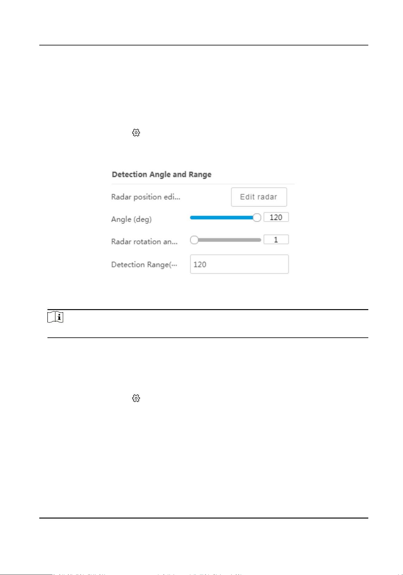
Chapter 9 Detecon Display Sengs
9.1 Set Detecon Angle and Range
Steps
1.
Select the radar and click in the client soware, or enter the IP address of the radar in the
address bar of the web browser. Go to Radar → Parameter Cong → Detecon Display Sengs
→ Detecon Angle and Range .
Figure 9-1 Set Detecon Angle and Range
2.
Slide the bar to set the radar angle and radar rotaon angle, and set the detecon range.
Note
The system should perform terrain learning again aer you edit the angle or the rotaon angle.
3.
Click Set to save the sengs.
9.2 Set Track
Steps
1.
Select the radar and click
in the client soware, or enter the IP address of the radar in the
address bar of the web browser. Go to Radar → Parameter Cong → Detecon Display Sengs
→ Track Sengs .
Security Radar User Manual
76
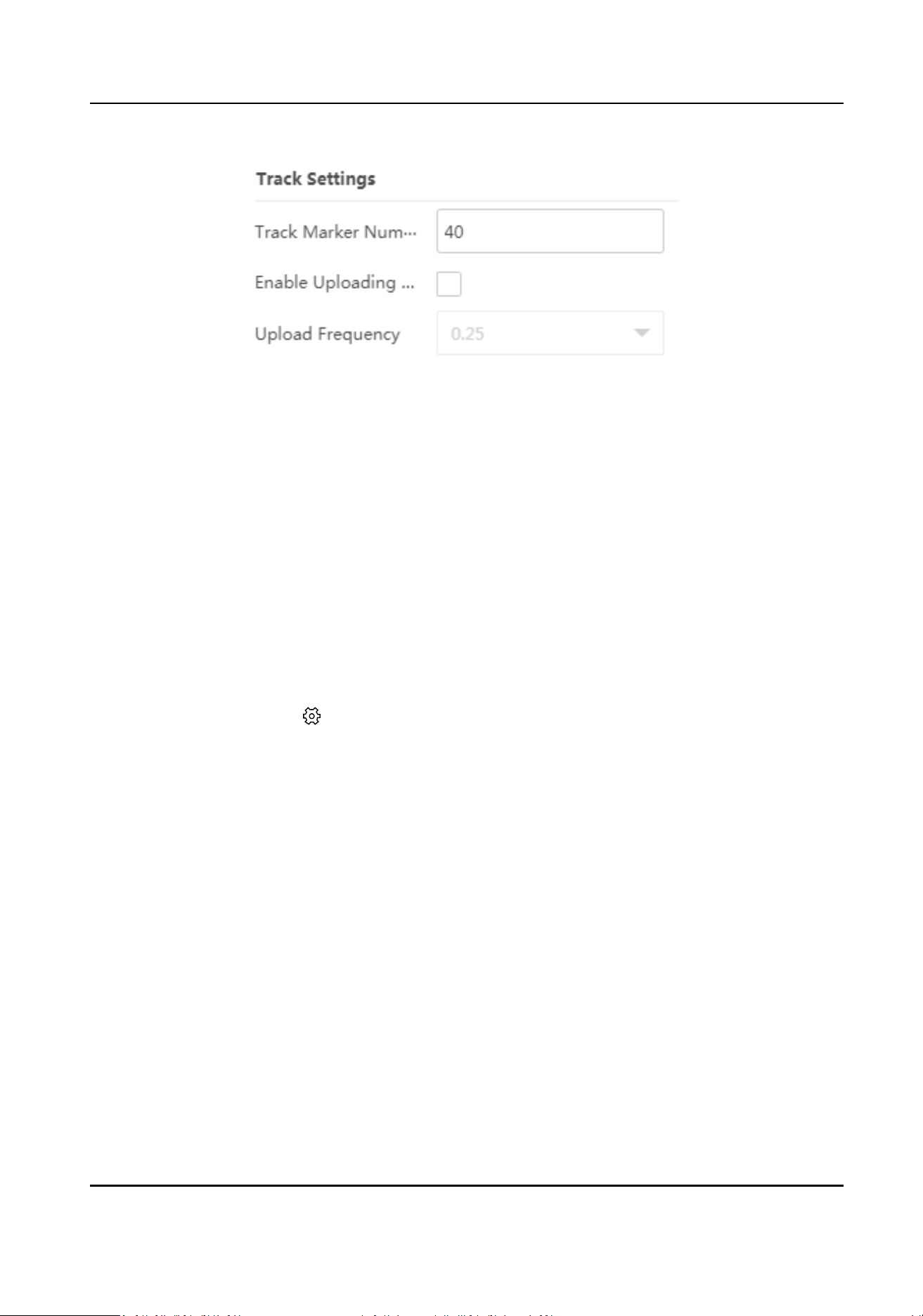
Figure 9-2 Set Track
2.
Set the parameters.
Track Marker Number
Edit the track marker number to control the track length. The default is 40.
Uploading Frequency
Check Enable Uploading Frequency, and set Uploading Frequency.
3.
Click Set to save the
sengs.
9.3 Set Radar Coordinate
Set the radar latude, longitude, and orientaon.
Steps
1.
Select the radar and click
in the client soware, or enter the IP address of the radar in the
address bar of the web browser. Go to Radar → Parameter Cong → Detecon Display Sengs
→ Radar Coordinate Sengs .
Security Radar User Manual
77
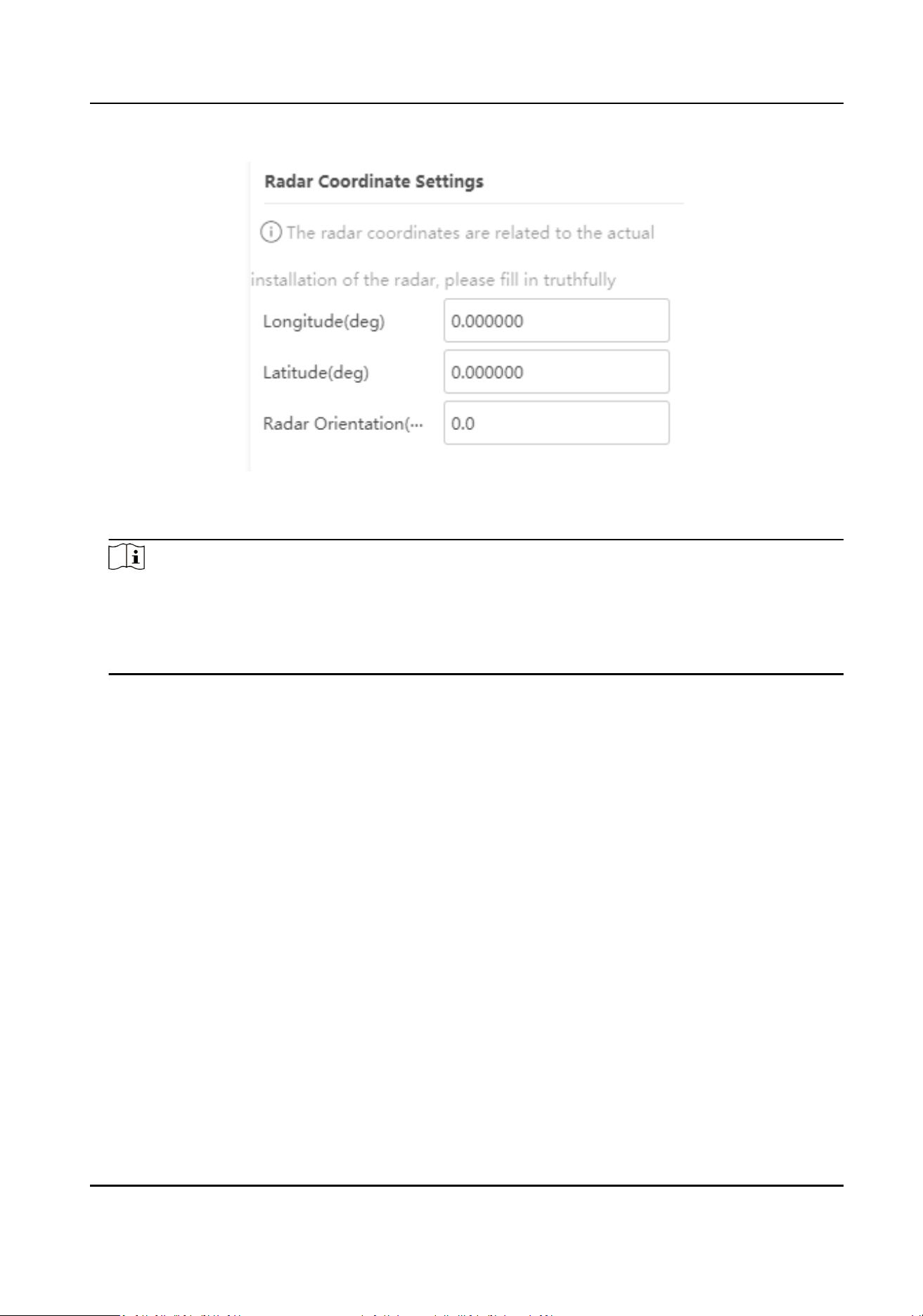
Figure 9-3 Set Radar Coordinate
2.
Set the radar Longitude, Latude, and Radar Orientaon.
Note
●
The radar orientaon is the clockwise angle between the true north direcon and the radar
center line. You can place your mobile phone on the back of the radar and use the applicaon
with compass funcons to get this angle.
●
The radar coordinates are related to the actual
installaon of the radar. Please enter truthfully.
3.
Click Set to save the sengs.
Security Radar User Manual
78
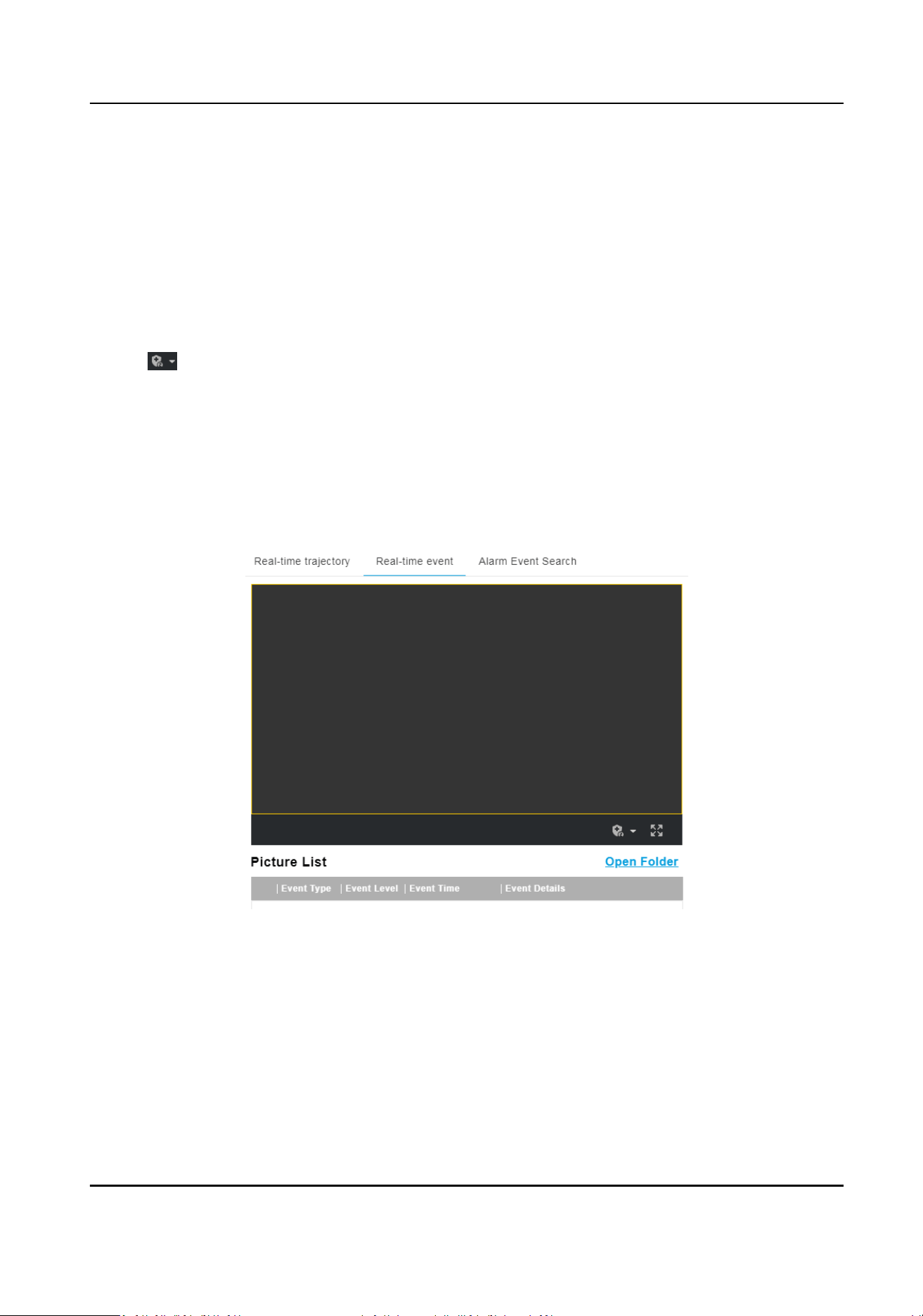
Chapter 10 View Alarm Informaon
10.1 View Real-Time Event
You can arm the radar via the web browser, and view the real-me event details.
Steps
1.
Go to Radar → Real-Time Event .
2.
Click to select the arming level.
-
Level 1 Arming can only connect one client or web. The uploaded pictures will not be stored
in the storage card. The pictures in the storage card will be uploaded to the level 1 arming.
-
Level 2 Arming can connect three clients or webs. The pictures will be uploaded to the client/
web, and stored in the storage card.
-
Disarming is to cancel the alarm status or
real-me picture.
3.
Click Arming.
4.
View the alarm event details in the picture list.
Figure 10-1 Real-Time Event
5.
Oponal: Click Open Folder to open the saving path of captured pictures.
10.2 Search Alarm Event
The device supports searching and playing back the alarm events.
Security Radar User Manual
79
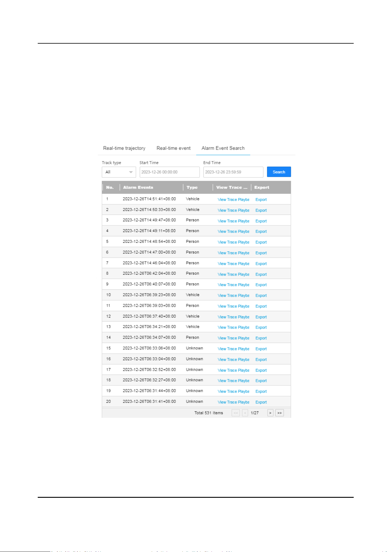
Before You Start
Set record and storage before searching and playing back alarm events.
Steps
1.
Click E-map in the client
soware, or enter the IP address of the radar in the address bar of the
web browser. Go to Radar → Alarm Event Search .
2.
Set the search condions, and click Search.
The searched alarm events will display in the list.
Figure 10-2 Search Alarm Event
3.
Click View Trace Playback and click Playto play back the alarm event.
4.
Click Export, and select Radar Track or Video Recording Trace to export to the
specic saving
path of the computer.
Security Radar User Manual
80

Chapter 11 System Conguraon
11.1 System Sengs
View the device informaon and status, set me synchronizaon, and so on.
Basic Informaon
Select the radar in the client soware and click , or enter the IP address of the radar in the
address bar of the web browser. Go to Conguraon → System → System Sengs → Basic
Informaon .
You can edit Device Name and Device No. View the device type, serial No., version, algorithm
version, etc.
Device Status
Select the radar in the client soware and click , or enter the IP address of the radar in the
address bar of the web browser. Go to
Conguraon → System → System Sengs → Device
Status .
You can view the device status, including device IP address, CPU usage, used memory, available
memory, etc.
Time
Sengs
Select the radar in the client soware and click , or enter the IP address of the radar in the
address bar of the web browser. Go to
Conguraon → System → System Sengs → Time
Sengs .
Select Sync Mode and click Save.
NTP
Synchronizaon
Select it to synchronize the device me with that of the NTP server. Set Server IP, NTP Port, and
Interval. Click NTP Test to test if the connecon between the device and the server is normal.
Manual Synchronizaon
Select it to synchronize the device me with that of the computer. Set me manually, or check
Sync. with computer
me.
SDK
If the remote host has been set for the device, select it to synchronize me via the remote host.
No
Select it to disable me synchronizaon.
All
Select it, and you can select any mode above.
Security Radar User Manual
81
DST
Select the radar in the client soware and click , or enter the IP address of the radar in the
address bar of the web browser. Go to Conguraon → System → System Sengs → DST .
Check Enable DST, and set the DST start
me, end me, and bias. Click Save.
11.2 System Maintenance
You can reboot the device, restore default sengs, import/export conguraon le, or upgrade
the device remotely.
System Maintenance
Select the radar and click in the client soware, or enter the IP address of the radar in the
address bar of the web browser. Go to Conguraon → System → Maintenance → Upgrade &
Maintenance .
Reboot
Click Reboot to reboot the device.
Note
You can also click Reboot on the upper right corner of the page to reboot the device.
Simply Restore Device Parameters
Click Restore to restore all the parameters except for admin user
informaon and wired
network parameters to default sengs.
Fully Restore to Factory Sengs
Click Restore Factory Sengs to restore all parameters to the factory sengs.
Export Data
Click Export and you can export the device conguraon parameters, debug le, or diagnosis
informaon to the computer. You need to set an encrypon password when exporng
conguraon parameters.
Upgrade
Click Browse and select an upgrade le from the computer and click Upgrade to upgrade the
device remotely.
Cauon
Do not power o or refresh the page when the device is upgrading. The device will reboot
automacally aer upgrading is completed.
Import Data
Security Radar User Manual
82
Click Browse to select a conguraon le from the computer and click Import to import
conguraon parameters to the device. You need to enter the password set for exporng the
conguraon parameters.
Cauon
The device that imports the conguraon le needs to match the model and version of the
device from which the conguraon le is exported.
Search Log
Select the radar and click in the client soware, or enter the IP address of the radar in the
address bar of the web browser. Go to
Conguraon → System → Maintenance → Log Search .
Set search condions, and click Search to get the log list. You can click Export to export the log
informaon.
11.3 Security Management
Security Service
Select the radar and click in the client soware, or enter the IP address of the radar in the
address bar of the web browser. Go to Conguraon → System → Security → Security Service .
Soware
Enable User Lock
If a user enters an incorrect password for more than 5
mes when logging in, the account
will be locked.
SSH Service
If enabled, you should set the SSH port.
Log Audit Service
The security audit logs refer to the security operaon logs. You can search and analyze the
security log
les of the device so as to nd out the illegal intrusion and troubleshoot the
security events. Security audit logs can be saved on device internal storage. The log will be
saved every half hour aer device boong. Due to limited storage space, you are recommended
to save the logs on a log server. Enable system log service, and set the IP address and port of the
log server. The device will upload the security audit logs to the log server regularly.
Timeout Logout
Enable
meout logout for stac page. If there is no operaon in the set Max. Timeout, the
account will log out
automacally.
Password Validity Period
Security Radar User Manual
83
Select Validity Type. Select Permanent, and the password will be permanently valid. Select
Daily and set Password Expiry Time. It will prompt you that the password is expired according
to the set password expiry me, and you need to set the new password.
Security Sengs
Select the radar and click in the client soware, or enter the IP address of the radar in the
address bar of the web browser. Go to Conguraon → System → Security → Security Sengs .
Select RTSP Authencaon.
digest
Digest
authencaon with higher safety.
11.4 Manage User
The administrator can add, modify, or delete other accounts, and grant dierent permissions to
dierent user levels.
Steps
1.
Select the radar and click
in the client soware, or enter the IP address of the radar in the
address bar of the web browser. Go to Conguraon → System → User Management → User
List .
2.
Select Password Level.
The password level of the added user should conform to the selected level.
3.
Add a user.
1) Click Add.
2) Enter User Name and select Type.
3) Enter Admin Password, New Password, and
conrm the password.
Cauon
To increase security of using the device on the network, please change the password of your
account regularly. Changing the password every 3 months is recommended. If the device is
used in high-risk environment, it is recommended that the password should be changed every
month or week.
4) Assign remote permission to users based on needs.
User
Users can be assigned permission of viewing live video and changing their own passwords,
but no permission for other operaons.
Operator
Operators can be assigned all permission except for operaons on the administrator and
creang accounts.
5) Click OK.
4.
Oponal: You can do the following operaons.
Security Radar User Manual
84

Change the password and permission Click to change the password and permission.
Delete the user Click to delete the user.
Security Radar User Manual
85
Appendix A. Indicator Descripon
The indicator status descripon of the radar:
Table A-1 Indicator Descripon
Indicator Radar Status
Solid Green Radar Powered on
Solid Red Zone Alarm Occurred
Flashing Red and Green Radar Network Disconnecon/Radar Sensor Excepon
When formang, the red and green LED ashes for 6 mes,
indicang that the formang was successful.
Security Radar User Manual
86
Appendix B. FAQ
B.1 Why Is It Required to Remove Reecve Objects from the Radar
Area?
When there are reecve objects in the radar applicaon scene, such as at glass or large-area
metal objects, the radar will produce mulpath eects, that is, the people reect the signal from
the radar to the large-area metal objects or
at glasses, and the large-area metal objects or at
glasses reect the signal again to the receiving end of the radar, thus there will be a false alarm.
Since the glasses are
at and the reecon is concentrated, there may be a false alarm when there
are glasses in the radar scene. The higher the sensivity, the more probability to trigger a false
alarm.
B.2 How to Solve the Problem that the Radar is not Shown in the Device
List on the Radar Page?
When the radar is adding failed or the radar’s port is incorrect, you cannot nd the radar in the
device list.
You should delete the radar and add it to the client soware again.
Note
The radar’s port is 80.
B.3 How to Solve the Problem that No Reference Point is on the Frame
While Seng the Speed Dome Inial Posion?
If the speed dome is
lted, it may cause that the reference point is above the center of the frame
or outside the frame while
seng the speed dome inial posion. In this case, you should adjust
the maximum elevaon angle of the speed dome as follows.
Steps
1.
Enter the IP address of the speed dome in the web browser to enter the web client.
2.
Click
to expand the PTZ list on the Live View page, and then click to enter the main menu of
the speed dome.
Security Radar User Manual
87
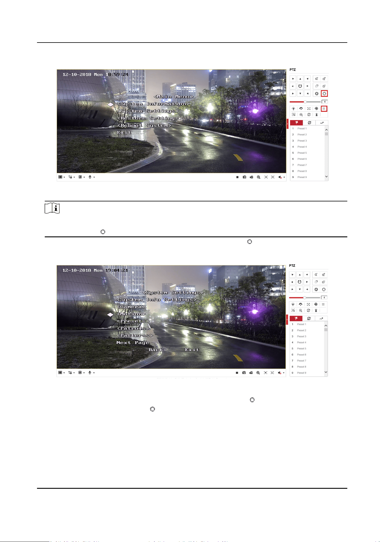
Figure B-1 The Main Menu of Speed Dome
Note
You can adjust the cursor for menu selecon by clicking the up and down direcon keys in the
PTZ list, and click to enter the selected item.
3.
Adjust the cursor to System Sengs in the main menu and click . And then adjust the cursor
to
Moon and click to enter the page.
Figure B-2 Moon
4.
Adjust the cursor to Next Page in the sport mode menu and click . And then adjust the cursor
to Max Ele Angle (DEG) and click to enter the page.
Security Radar User Manual
88
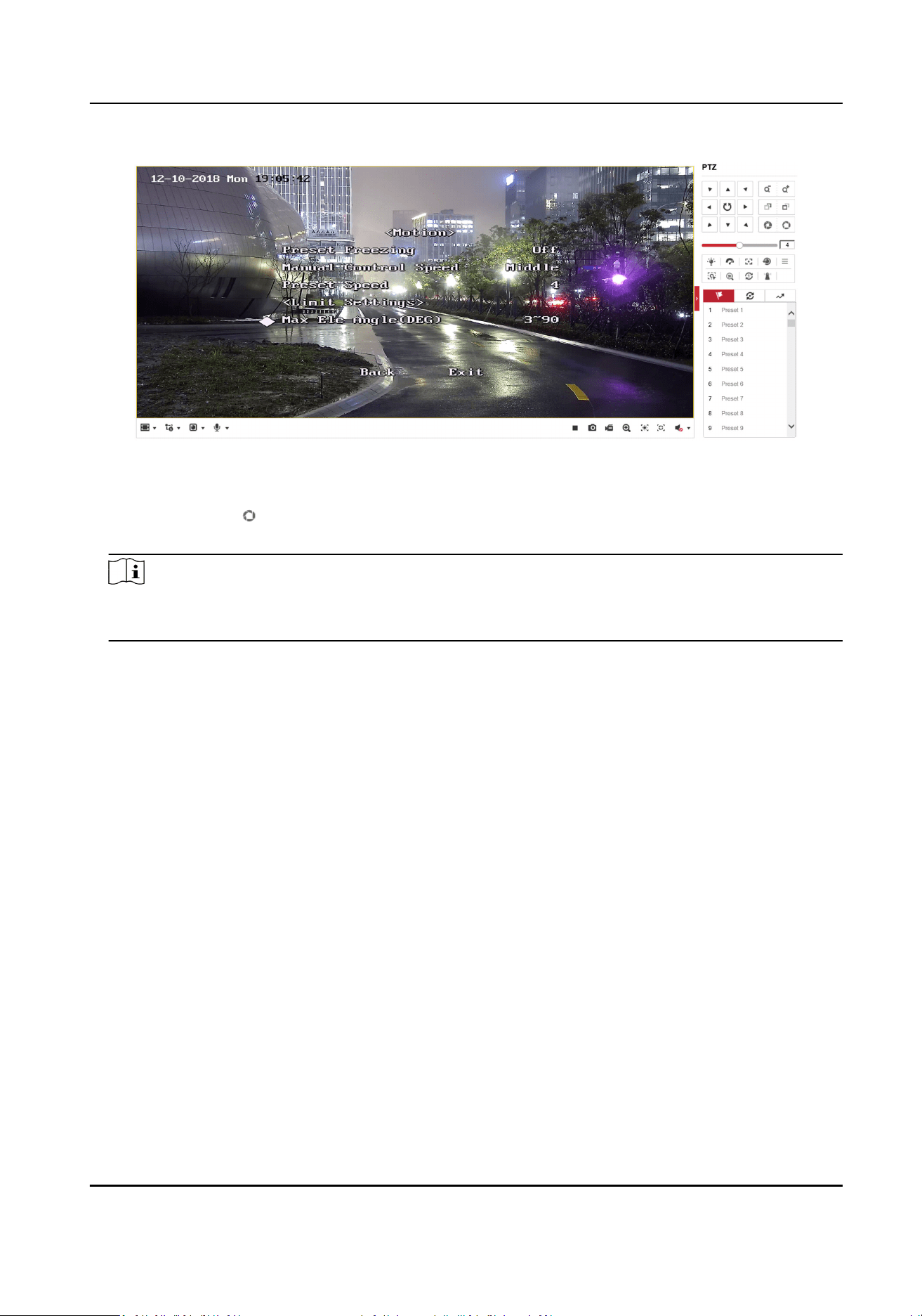
Figure B-3 Maximum Elevaon Angle Adjustment
5.
Click up and down direcon keys in the PTZ list to adjust the maximum elevaon angle, and then
you need to click to save the sengs.
6.
Adjust the cursor to Exit to exit the menu.
Note
You need to reset the speed dome inial posion aer the maximum elevaon angle
adjustment.
B.4 What Makes a Failed Arming?
The following two condions will make a failed arming:
●
In the E-Map page, click Finish to exit the eding mode. If there is a moving target in the warning
zone when you click Arm Radar → Arm All Radars to arm radars, it is impossible to enable
mandatory arming,
resulng in failed arming.
●
The current status of radar is oine.
B.5 How to Raise the Precision of Camera Tracking?
●
Check if the speed dome inial posion is set, if not, please set the speed dome inial posion.
●
Check if the
calibraon points are correct. Pay aenon to the situaon that the target is
intercepted when calibrang. If the calibraon points are error, please calibrate again.
●
Check if the
calibraon posions is equally distributed when you set the mul-point calibraon.
●
Do not move the speed dome manually aer the calibraon. If the speed dome is manually
moved, please reset the inial posion of the speed dome and then calibrate again.
Security Radar User Manual
89

B.6 How to View the Completed Calibraon Points?
Before You Start
Camera calibraon was performed and calibraon points were successfully saved.
Steps
1.
In the client soware, click E-map to enter the map page, click Edit in the upper right corner to
enter the
eding mode.
2.
Click Radar Sengs → Smart Linkage Sengs to enter the calibraon page.
3.
Select a radar in the drop-down list.
4.
Click
Informaon to view the calibraon inforamon.
B.7 What Should I Do if the
Communicaon Failure is Displayed When
Conguring the Frequency?
If "Radar module communicaon failed" is displayed when saving the sengs, click Save for
several
mes unl the sengs is successful.
Security Radar User Manual
90

UD36209B