
Loading ...
Loading ...
Loading ...
AXIS P1204 Network Camera
Hardware Overview
NOTICE
To prevent corruption of recordings, the SD card should be unmounted before removal. To unmount, go to Setup > System
Options > Storage > SD Card and click Unmount.
Control button - The control button is used for:
• ConnectingtoanAXISVideoHostingSystemservice.Seepage 33. To connect, press and hold the button for about
1 second until the Status LED flashes gree n.
• ConnectingtoAXISInternetDynamicDNSService. Seepage 33. To connect, press and hold the button for
about 3 seconds.
• Resetting the product to factory default settings. See page 40.
Power connector - 2-pin terminal block for power input.
I/O terminal connector - Use in applications for e.g. motion detection, event triggering, time lapse recording and alarm notifications.
In addition to an auxiliary pow e r and a GND pin, the I/O terminal connector provides the interface to:
• Digital output – For connecting external devices such as relays and LEDs. Connected devices can be activated by
the VAPIX® Application Prog ramm ing Interface, output buttons on the Live View page or by an Action Rule. The
output will show as active (shown under System Options > Ports & Devices) if the alarm device is activated.
• Digital input – An alarm input for connecting devices that can toggle between an open and closed circuit, for
example: PIRs, door/window contacts, glass break detectors, etc. When a signal is received the state changes and
the input becomes active (shown under System Options > Ports & Devices).
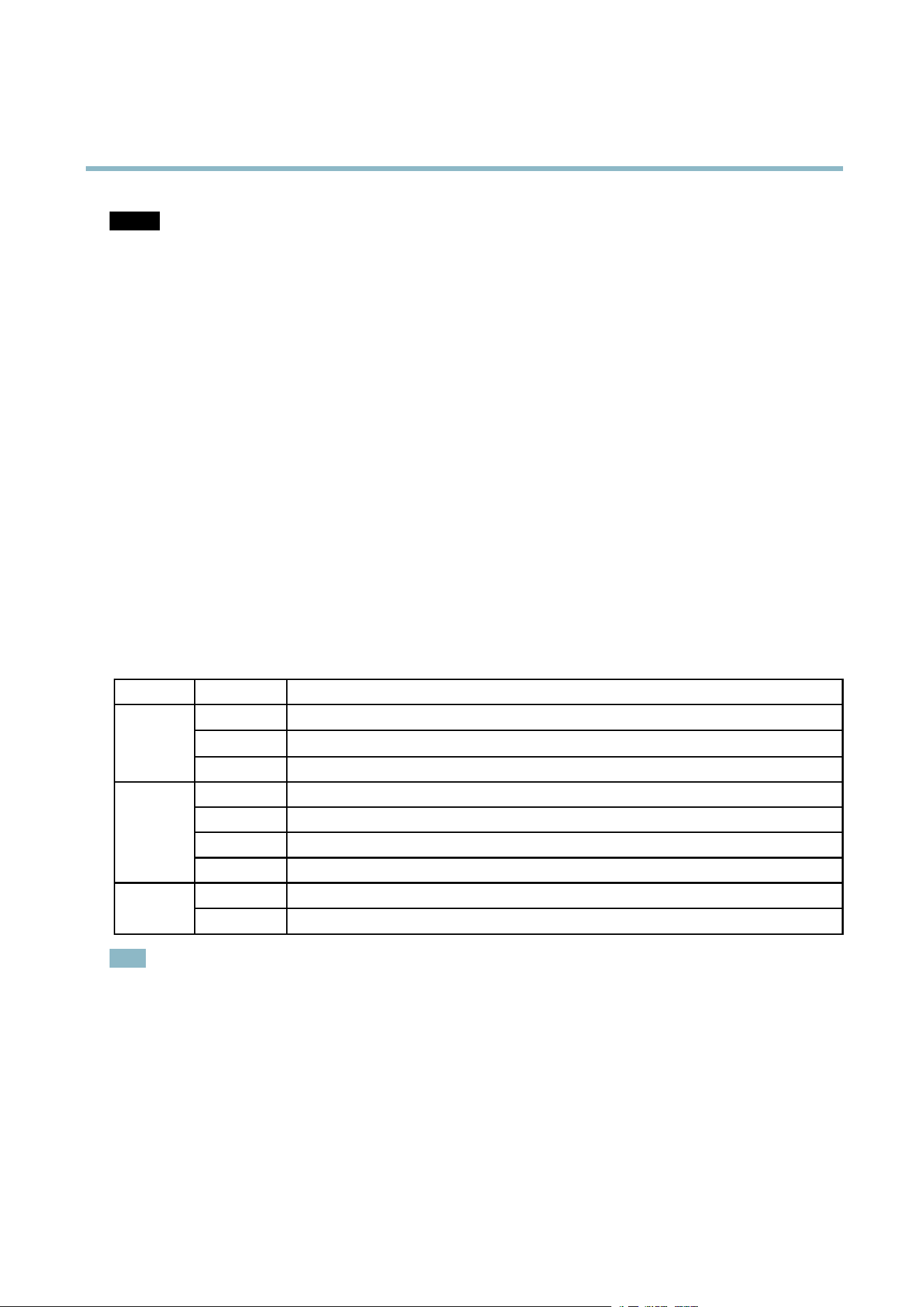
LED Indica tors
LED
Color
Indication
Green
Steady for connection to a 100 MBit/s network. Flashes for network activity.
Amber
Steady for connection to a 10 MBit/s network. Flashes for network activity.
Network
Unlit No network connection.
Green Steady green for no rmal operation.
Amber
Steady during startup and when restoring settings.
Red
Slow flash for failed upgrade.
Status
Unlit No connection between sensor unit and main unit.
Green
Normal operation.
Power
Amber
Flashes g
reen/amber during firmware upgrade.
Note
• The Status LED can be configured to be unlit during normal operation. To configure, go to Setup > System Options >
Ports & Devices > LED. See the online help for more in forma tion.
•T
he Status LED can be configured to flash whil e an event is active.
• The Status LED can be configured to flash for identifying the unit. Go to Setup > System Options > Maintenance .
Shorten Sensor Unit Cable
The sensor unit is delivered with a 8 m (26 ft) cable.
To shorten the cable follow these steps:
5
Loading ...
Loading ...
Loading ...