Loading ...
Loading ...
Loading ...
PRODUCT DATA | 37
Product Data
'XHWRRXUSROLF\RIFRQWLQXRXVSURGXFWLQQRYDWLRQVRPHVSHFL¿FDWLRQVPD\FKDQJHZLWKRXWQRWL¿FDWLRQ
©
/*(OHFWURQLFV86$,QF(QJOHZRRG&OLIIV1-$OOULJKWVUHVHUYHG³/*´LVDUHJLVWHUHGWUDGHPDUNRI/*&RUS
ELECTRICAL CONNECTIONS
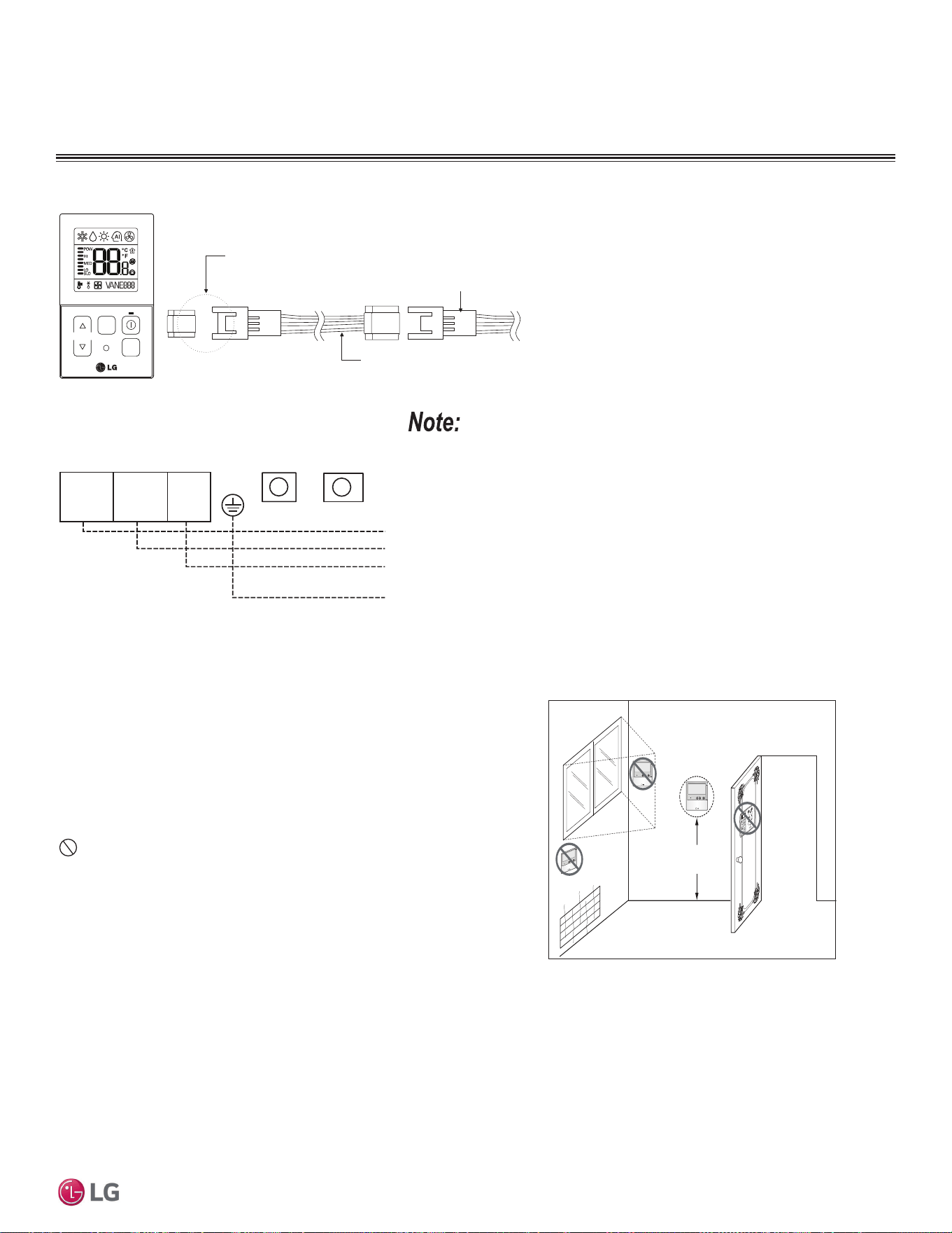
Figure 23: Proper Location for the Wired Controller.
4 to 5 feet
above the floor
NO
NO
NO
YES
Remote Controlle r
TEMP
Remote Controlle r
TEMP
Re
m
ot
e
Co
nt
r
o
l
l
e
r
TEMP
Wired Controller Placement
Wired controllers include a sensor to detect room temperature. To
maintain comfort levels in the conditioned space, the wired control-
ler must be installed in a location away from direct sunlight, high
humidity, and where it could be directly exposed to cold air. Control-
ler must be installed four (4) to five (5) feet above the floor where its
LED display can be read easily, in an area with good air circulation,
and where it can detect an average room temperature.
Do not install the wired controller near or in:
• Drafts or dead spots behind doors and in corners.
• Hot or cold air from ducts.
• Radiant heat from the sun or appliances.
• Concealed pipes and chimneys.
• An area where temperatures are uncontrolled, such as an outside
wall.
Assigning the Thermistor for Temperature Detection
Each indoor unit includes a return air thermistor assigned to sense the temperature. If a wired controller is installed, there is a choice of
sensing temperature with either the indoor unit return air thermistor or the thermistor in the wired controller. It is also an option to set both
thermistors to sense temperature so that indoor unit bases its operation on the first thermistor to reach the designated temperature differen-
tial.
Figure 24: PZCWRC1 LG Wired Remote Extension Cable for Use with the Mega 115V.
Verify the connectors are properly inserted.
C/BOX Cable (Plug type)
Extension cable
To Indoor Unit
CN-REMO
Terminal
TEMP
FAN
SPEED
OPER
MODE
Figure 25: Wired Controller Connection on the Mega 115V
Indoor Unit Terminal Block.
:KHQXVLQJ¿HOGVXSSOLHGFRQWUROOHUFDEOHPDNHVXUHWRFRQQHFWWKH\HOORZWR\HOORZ
(communications wire), red to red (12V power wire), and black to black (ground wire)
terminals from the remote controller to the indoor unit terminal blocks.
Indoor Unit Terminal Block
1(L1 ) 2
GND
3
GRN /
YLW
BR
BL
RD
CN-REMOCN-CC
Loading ...
Loading ...
Loading ...