Loading ...
Loading ...
Loading ...
36 | PRODUCT DATA
Single Zone Mega Wall Mounted Engineering Manual
'XHWRRXUSROLF\RIFRQWLQXRXVSURGXFWLQQRYDWLRQVRPHVSHFL¿FDWLRQVPD\FKDQJHZLWKRXWQRWL¿FDWLRQ
©
/*(OHFWURQLFV86$,QF(QJOHZRRG&OLIIV1-$OOULJKWVUHVHUYHG³/*´LVDUHJLVWHUHGWUDGHPDUNRI/*&RUS
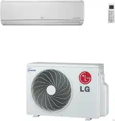
ELECTRICAL CONNECTIONS
Controller Options
Single Zone Mega and Mega 115V Wall Mount systems include a wireless handheld remote controller
(Model Nos. AKB74955602 [Mega] and AKB73456121 [Mega 115V]). Optional LG-suppled wired control-
lers are available for the Mega 115V units. See “Functions, Controls, Options”, or contact an LG repre-
sentative for more information.
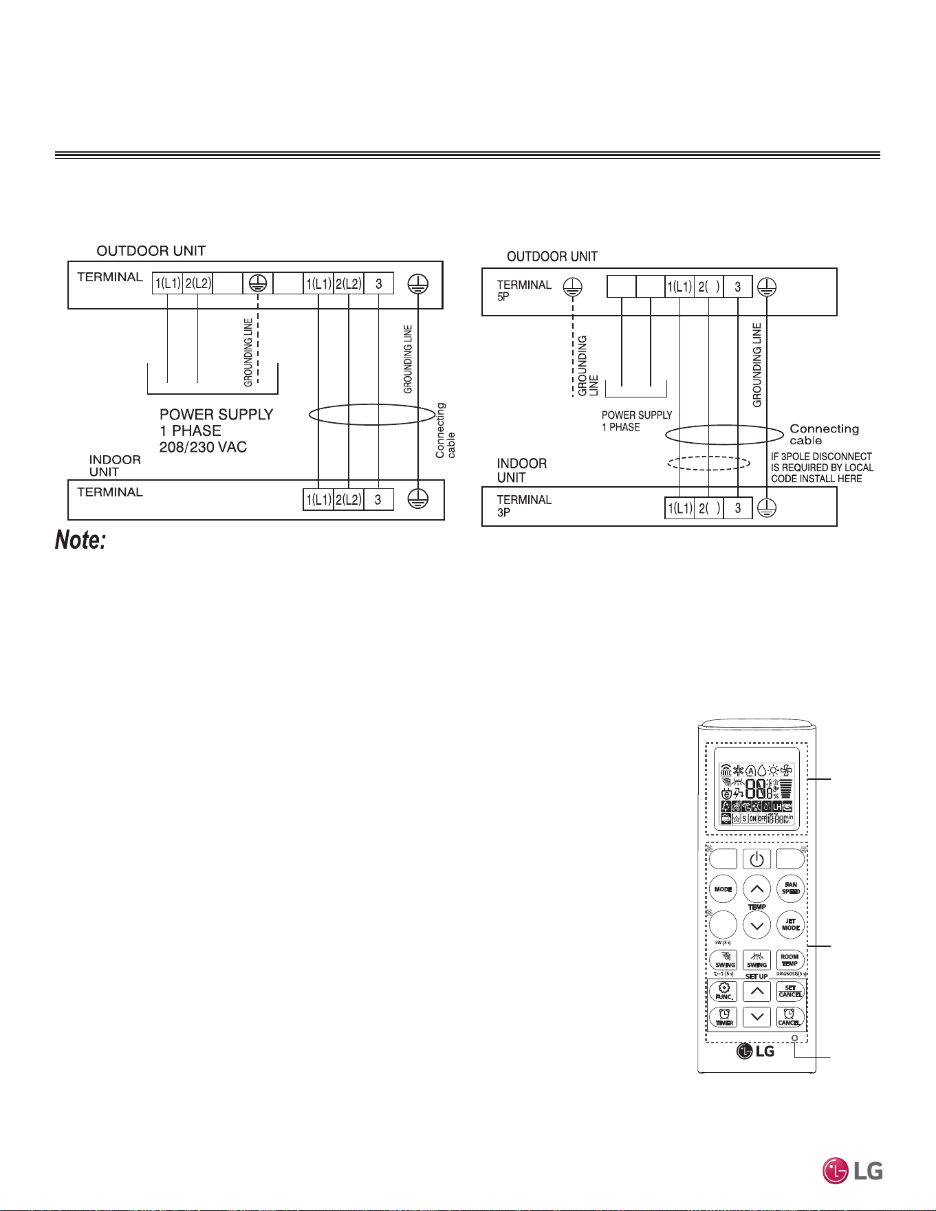
Wireless Handheld Remote Controller features:
• Display Panel: Displays operation conditions.
• On / Off Button: Turns system operation on and off.
• Mode Button: Selects the operation mode: Cooling, Heating, Auto, Dry
(Dehumidification), or Fan.
• Temp Up / Down Buttons: Adjusts the desired room temperature in the different modes.
• Fan Speed Button: Sets desired fan speed.
• Reset: Initializes the handheld remote control settings.
Wired Controller Connections
Optional controllers (see “Functions, Controls, Options”, or contact an LG representative for more infor-
mation) can connect to the Single Zone Mega 115V Wall Mount indoor unit in one of two different ways.
1. LG Wired Remote Extension Cable with Molex plug (PZCWRC1; sold separately) that connects to the
CN-REMO terminal on the indoor unit PCB.
2. Field-supplied controller cable that connects to the indoor unit terminal block (must be at least
UL2547 or UL1007, and at least FT-6 rated if local electric and building codes require plenum cable
usage). Communication cable from indoor unit to remote controller(s) is to be 22 AWG, 3-conductor,
twisted, stranded, unshielded. Wiring must comply with all applicable local and national codes.
Figure 20: Terminal Block Wiring Diagram LS180HEV2, LS240HEV2.
Display
Screen
Button
*
*
*
RESET
• Use a conduit for the communications cable / power wiring from the outdoor unit to the indoor units.
• Make sure the communications cable / power wiring from the outdoor units to the indoor units, and the power wiring to the outdoor unit are
separate, otherwise, the outdoor unit operation will be affected by electrical noise and will malfunction or fail.
LSU090HXV, LSU120HXV
N
N
N
L
115 VAC
LS180HEV2, LS240HEV2
Figure 21: Terminal Block Wiring Diagram LS090HXV, LS120HXV
Figure 22: AKB74955602 Wire-
less Handheld Remote Controller.
Buttons on the AKB73456121 will
differ.
Loading ...
Loading ...
Loading ...