SINGLE ZONE MEGA AND MEGA 115V
WALL MOUNTED
ENGINEERING MANUAL
3/4, 1, 1-1/2, and 2 Tons
Mega Models:
LS090HEV2
LS120HEV2
LS180HEV2
LS240HEV2
3/4 and 1 Tons
Mega 115V Models:
LS090HXV LS120HXV

For continual product development, LG Electronics U.S.A., Inc., reserves the right to change specifications without notice.
© LG Electronics U.S.A., Inc.
PROPRIETARY DATA NOTICE
This document, as well as all reports, illustrations, data, information,
and other materials are the property of LG Electronics U.S.A., Inc., and are
disclosed by LG Electronics U.S.A., Inc. only in confidence.
This document is for design purposes only.
A summary list of safety precautions is on page 4.
For more technical materials such as submittals, catalogs, installation,
owner’s, and service manuals, visit www.lghvac.com.
TABLE OF CONTENTS
TABLE OF SYMBOLS
DANGER
This symbol indicates an imminently hazardous situation which, if not avoided, will result in death or serious injury.
This symbol indicates a potentially hazardous situation which, if not avoided, could result in death or serious injury.
CAUTION
This symbol indicates a potentially hazardous situation which, if not avoided, may result in minor or moderate injury.
This symbol indicates situations that may result in equipment or property damage accidents only.
This symbol indicates an action that must not be performed.
Unit Nomenclature...........................................................................................................................................................................................................4
LG Air Conditioner Technical Solution (LATS)..........................................................................................................................................................5-6
Mega and Mega 115V Product Data...................................................................................................................................................................7-48
Mechanical Specifications.........................................................................................................................................................................................8
General Data.........................................................................................................................................................................................................9
Electrical Data............................................................................................................................................................................................................12
Functions, Controls, Options.........................................................................................................................................................................................13
Outdoor Unit Dimensions.........................................................................................................................................................................................14-17
Indoor Unit Dimensions.........................................................................................................................................................................................18-20
Acoustic Data ........................................................................................................................................................................................................21-26
Refrigerant Flow Diagrams...................................................................................................................................................................................27-28
Wiring Diagrams--Indoor Units...................................................................................................................................................................................29-30
Wiring Diagrams--Outdoor Units..................................................................................................................................................................................31-33
Electrical Connections..........................................................................................................................................................................................27-30
Air Flow, External Pressure, Temp. Distribution.....................................................................................................................................................34-37
Accessories...........................................................................................................................................................................................................47-48
Mega and Mega 115V Performance Data-------------------------------------------------------------------------------------------------------------------------------49-58
Cooling Capacity Data..........................................................................................................................................................................................50-52
Heating Capacity Data..........................................................................................................................................................................................53-54
Maximum Heating Capacity Data..........................................................................................................................................................................................55-56
Equipment Selection Procedure ............................................................................................................................................................................57-58
Mega and Mega 115V Application Guidelines.................................................................................................................................................59-68
Placement Considerations .....................................................................................................................................................................................60-64
Installing Outdoor Unit Indoors .............................................................................................................................................................................65-67
Refrigerant Piping Design .....................................................................................................................................................................................68
INTRODUCTION | 3
Introduction
'XHWRRXUSROLF\RIFRQWLQXRXVSURGXFWLQQRYDWLRQVRPHVSHFL¿FDWLRQVPD\FKDQJHZLWKRXWQRWL¿FDWLRQ
©
/*(OHFWURQLFV86$,QF(QJOHZRRG&OLIIV1-$OOULJKWVUHVHUYHG³/*´LVDUHJLVWHUHGWUDGHPDUNRI/*&RUS
4 | PRODUCT DATA
Single Zone Mega Wall Mounted Engineering Manual
'XHWRRXUSROLF\RIFRQWLQXRXVSURGXFWLQQRYDWLRQVRPHVSHFL¿FDWLRQVPD\FKDQJHZLWKRXWQRWL¿FDWLRQ
©
/*(OHFWURQLFV86$,QF(QJOHZRRG&OLIIV1-$OOULJKWVUHVHUYHG³/*´LVDUHJLVWHUHGWUDGHPDUNRI/*&RUS
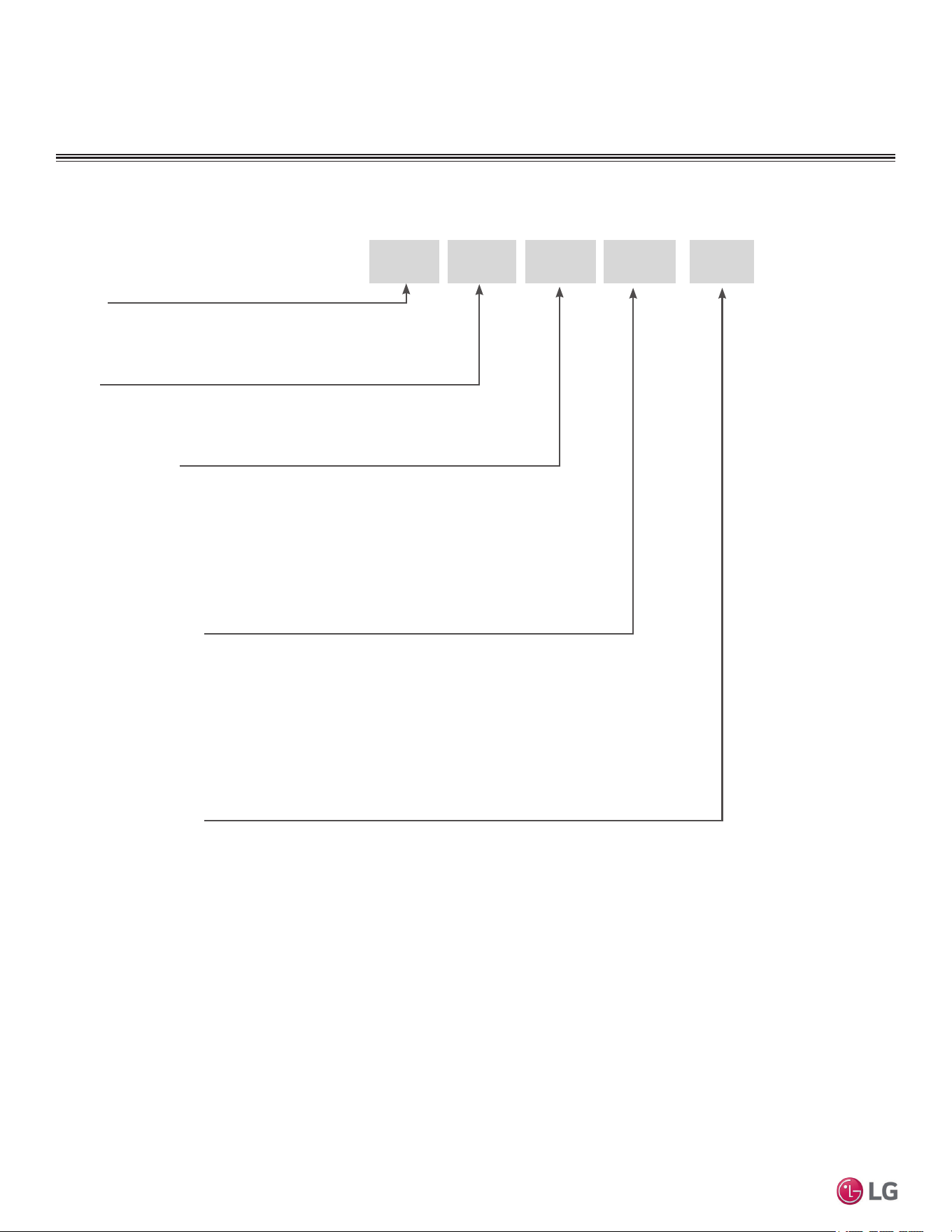
UNIT NOMENCLATURE
Single Zone Wall Mount Indoor and Outdoor Units
LS
N 090 HEV 2
Type
N = Indoor Wall Mount Unit
U = Outdoor Heat Pump Unit
Family
LA= Art Cool Premier / Gallery / Mirror
LS= High Efficiency Wall Mount / Standard / Mega
Generation or Revision
1 = First
2 = Second
3 = Third
4 = Fourth
Nominal Capacity
(Nominal cooling capacity in Btu/h)
090 = 9,000
120 = 12,000
180 = 18,000
240 = 24,000
300/307 = 30,000
360 = 36,000
Indoor/Outdoor Product
HEV = Mega
HXV = Mega 115V
HYV = Art Cool Premier
HVP = Art Cool Gallery
HSV = Art Cool Mirror, High Efficiency
HV = Standard
HLV = Extended Pipe
LG AIR CONDITIONER
TECHNICAL SOLUTION (LATS)
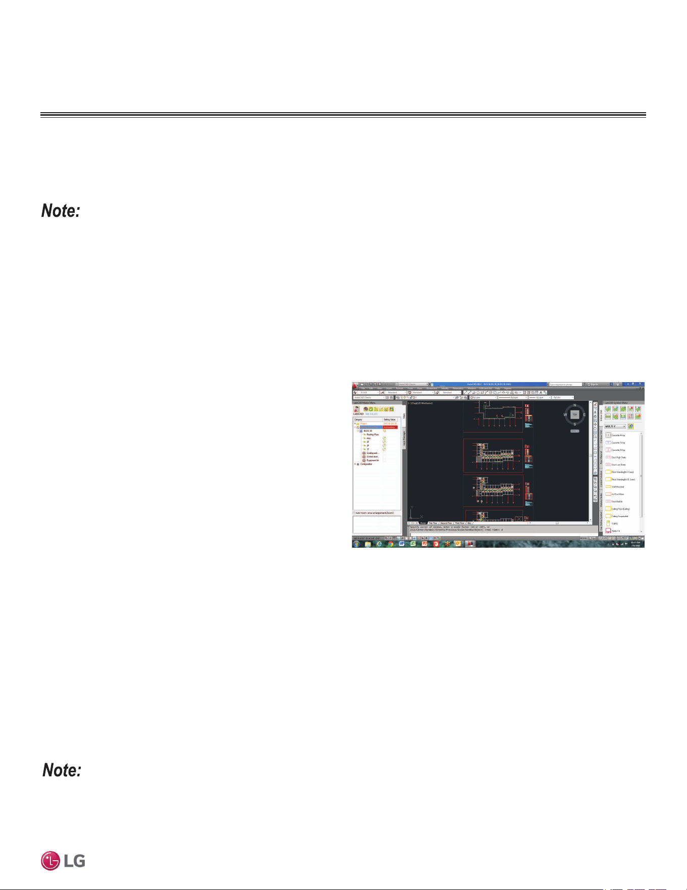
Figure 1: Example of LATS CAD2.
LG Air Conditioner Technical Solution (LATS) Software
A properly designed and installed refrigerant piping system is critical to the optimal performance of LG air-conditioning systems. To assist
engineers, LG offers, free of charge, LG Air Conditioner Technical Solution (LATS) software—a total design solution for LG air conditioning
systems. Contact your LG Rep for the best software program for your application.
To reduce the risk of designing an improper applied system or one that will not operate correctly, LG requires that LATS software be used on all
projects.
Formats
LATS is available to LG customers in three user interfaces: LATS HVAC, LATS CAD2, and LATS Revit. All three LATS formats are available
through www.myLGHVAC.com, or contact an LG Sales Representative.
LATS HVAC is a Windows
®
-based application that aids engineers in designing LG Variable Refrigerant Flow (VRF), Multi F / Multi F MAX,
Single-Zone, and Energy Recovery Ventilator (ERV) systems.
*Windows
®
is a registered mark of Microsoft
®
Corporation.
LATS CAD2 combines the LG LATS program with AutoCAD
®
software**. It permits engineers to layout and validate LG Multi V
Variable Refrigerant Flow (VRF), Multi F / Multi F MAX, Single-Zone,
and Energy Recovery Ventilator (ERV) systems directly into CAD
drawings.
LATS Revit integrates the LG LATS program with Revit
®
software**.
It permits engineers to layout and validate Multi V VRF systems
directly into Revit drawings.
**AutoCAD® and Revit® are both registered marks of Autodesk, Inc.
Features
All LG product design criteria have been loaded into the program,
making LATS simple to use: double click or drag and drop the com-
ponent choices. Build systems in Tree Mode where the refrigerant
system can be viewed. Switch to a Schematic diagram to see the electrical and communications wiring.
LATS software permits the user to input region data, indoor and outdoor design temperatures, modify humidity default values, zoning, specify
type and size of outdoor units and indoor units, and input air flow and external static pressure (ESP) for ducted indoor units.
The program can also:
• Import building loads from a separate Excel file.
• Present options for outdoor unit auto selection.
• Automatically calculate component capacity based on design
conditions for the chosen region.
• Verify if the height differences between the various system
components are within system limits.
• Provide the correct size of each refrigerant piping segment and LG
Y-Branches and Headers.
• Adjust overall piping system length when elbows are added.
• Check for component piping limitations and flag if any parameters
are broken.
• Factor operation and capacity for defrost operation.
• Calculate refrigerant charge, noting any additional trim charge.
• Suggest accessories for indoor units and outdoor units.
• Run system simulation.
Features depend on which LATS program is being used, and the type of system being designed.
INTRODUCTION | 5
Introduction
'XHWRRXUSROLF\RIFRQWLQXRXVSURGXFWLQQRYDWLRQVRPHVSHFL¿FDWLRQVPD\FKDQJHZLWKRXWQRWL¿FDWLRQ
©
/*(OHFWURQLFV86$,QF(QJOHZRRG&OLIIV1-$OOULJKWVUHVHUYHG³/*´LVDUHJLVWHUHGWUDGHPDUNRI/*&RUS
LATS Generates a Complete Project Report
LATS software also generates a report containing project design parameters, cooling and heating design data, system component perfor-
mance, and capacity data. The report includes system combination ratio and refrigerant charge calculations; and provides detailed bill of
material, including outdoor units, indoor units, control devices, accessories, refrigerant pipe sizes segregated by building, by system, by pipe
size, and by pipe segments. LATS can generate an Excel GERP report that can imported into the LG SOPS pricing and ordering system.
Proper Design to Install Procedure
LG encourages a two report design-to-install-procedure. After the
design engineer determines building / zone loads and other details,
the engineer opens the LATS program and inputs the project’s infor-
mation. When the design is complete, the “Auto Piping” and “System
Check” functions must be used to verify piping sizes, limitations, and
if any design errors are present. If errors are found, engineers must
adjust the design, and run Auto Piping and System Check again.
When the design passes the checks, then the engineer prints out
a project “Shop Drawing” (LATS Tree Diagram) and provides it to
the installing contractor. The contractor must follow the LATS Tree
Diagram when building the piping system, but oftentimes the design
changes on the building site:
• Architect has changed location and/or purpose of room(s).
• Outdoor unit cannot be placed where originally intended.
• Structural elements prevent routing the piping as planned.
• Air conditioning system conflicts with other building systems (plumbing, gas lines, etc.).
The contractor must mark any deviation from the design on the Shop Drawing, including as-built straight lines and elbows. This “Mark Up”
drawing must be returned to the design engineer or Rep, who must input contractor changes into the LATS file. (Copy the original LATS soft-
ware file, save and rename as a separate file, and modify all piping lengths by double-clicking on each length and editing information.) Like
the shop drawing, the Auto Piping and System Check must also be run on this new “As Built” drawing. The design engineer or Rep must then
provide the final As Built file to the contractor. The Mark Up version must be compared to the As Built version for:
• Differences in pipe diameter(s). If incorrect diameters have been installed, the piping must be changed out. If pipe diameters have changed,
check to see if Y-Branches will also need to be changed.
• Changes to outdoor unit and indoor unit capacities. Capacities changes will impact line length changes.
• Additional refrigerant charge quantity (“Trim Charge”). Trim charge will change if piping lengths and diameters change. The As Built version
must reflect installed piping lengths to ensure correct trim charge.
All documents submitted by the contractor, as well as the Shop Drawing and the As Built Drawing files must be provided for commissioning
purposes. Model and serial numbers for all system components must also be submitted. If the steps previously detailed are not followed, and
all documents are not provided to the commissioning agent, the project runs the risk of not being commissioned and voiding any limited war-
ranty LG offers on the equipment.
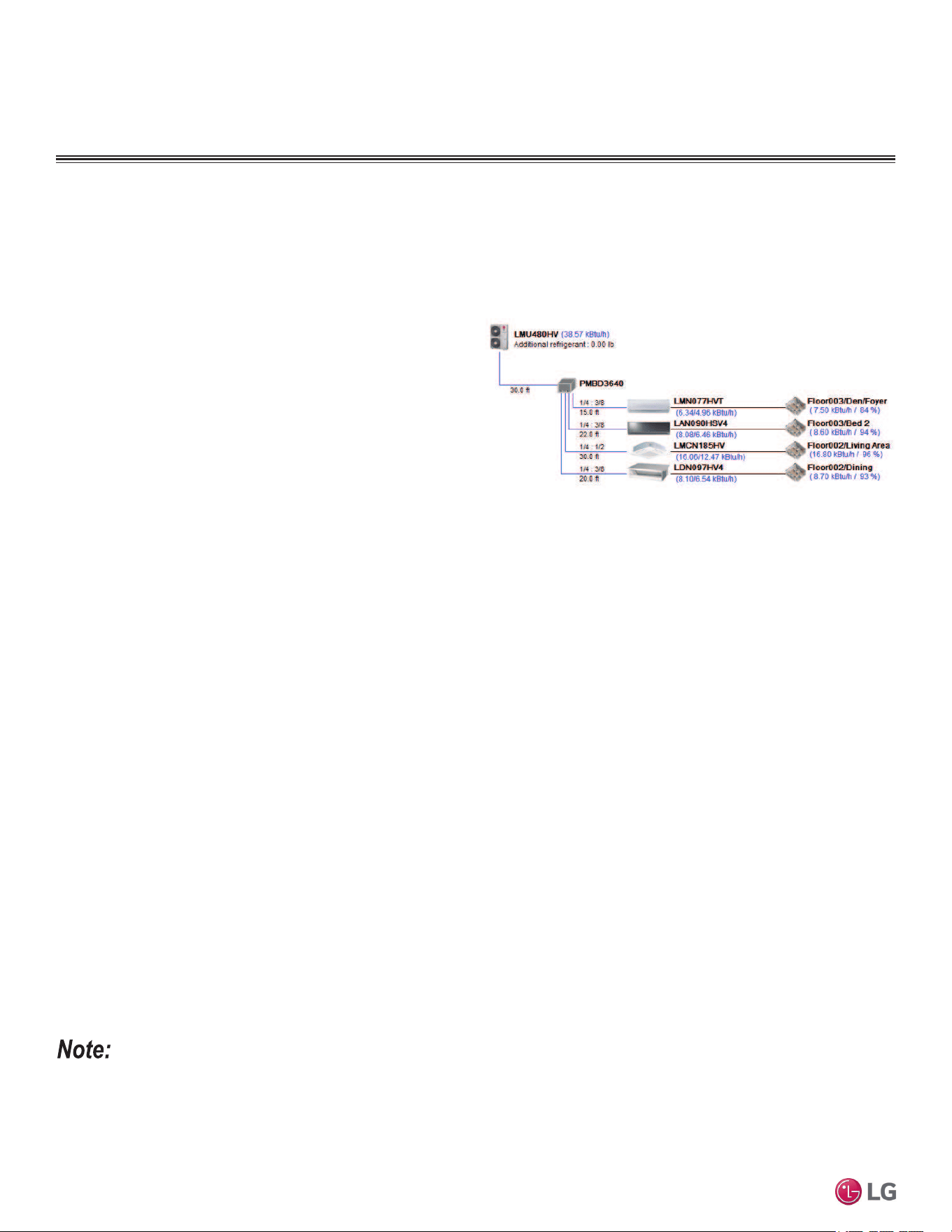
Figure 2: Example of a LATS Tree Diagram.
LG AIR CONDITIONER
TECHNICAL SOLUTION (LATS)
Contact your LG representative for the best software program for your application.
6 | INTRODUCTION
Single Zone Mega Wall Mounted Engineering Manual
'XHWRRXUSROLF\RIFRQWLQXRXVSURGXFWLQQRYDWLRQVRPHVSHFL¿FDWLRQVPD\FKDQJHZLWKRXWQRWL¿FDWLRQ
©
/*(OHFWURQLFV86$,QF(QJOHZRRG&OLIIV1-$OOULJKWVUHVHUYHG³/*´LVDUHJLVWHUHGWUDGHPDUNRI/*&RUS

PRODUCT DATA
Mechanical Specifications on page 8
General Data on page 9
Electrical Data on page 12
Functions, Controls, Options on page 13
Outdoor Unit Dimensions on page 14
Indoor Unit Dimensions on page 18
Acoustic Data on page 21
Refrigerant Flow Diagrams on page 27
Wiring Diagrams—Indoor Units on page 29
Wiring Diagrams—Outdoor Units on page 31
Electrical Connections on page 34
Air Flow, Static Pressure, and Temperature Distribution
on page 38
Accessories on page 47
8 | PRODUCT DATA
Single Zone Mega Wall Mounted Engineering Manual
'XHWRRXUSROLF\RIFRQWLQXRXVSURGXFWLQQRYDWLRQVRPHVSHFL¿FDWLRQVPD\FKDQJHZLWKRXWQRWL¿FDWLRQ
©
/*(OHFWURQLFV86$,QF(QJOHZRRG&OLIIV1-$OOULJKWVUHVHUYHG³/*´LVDUHJLVWHUHGWUDGHPDUNRI/*&RUS
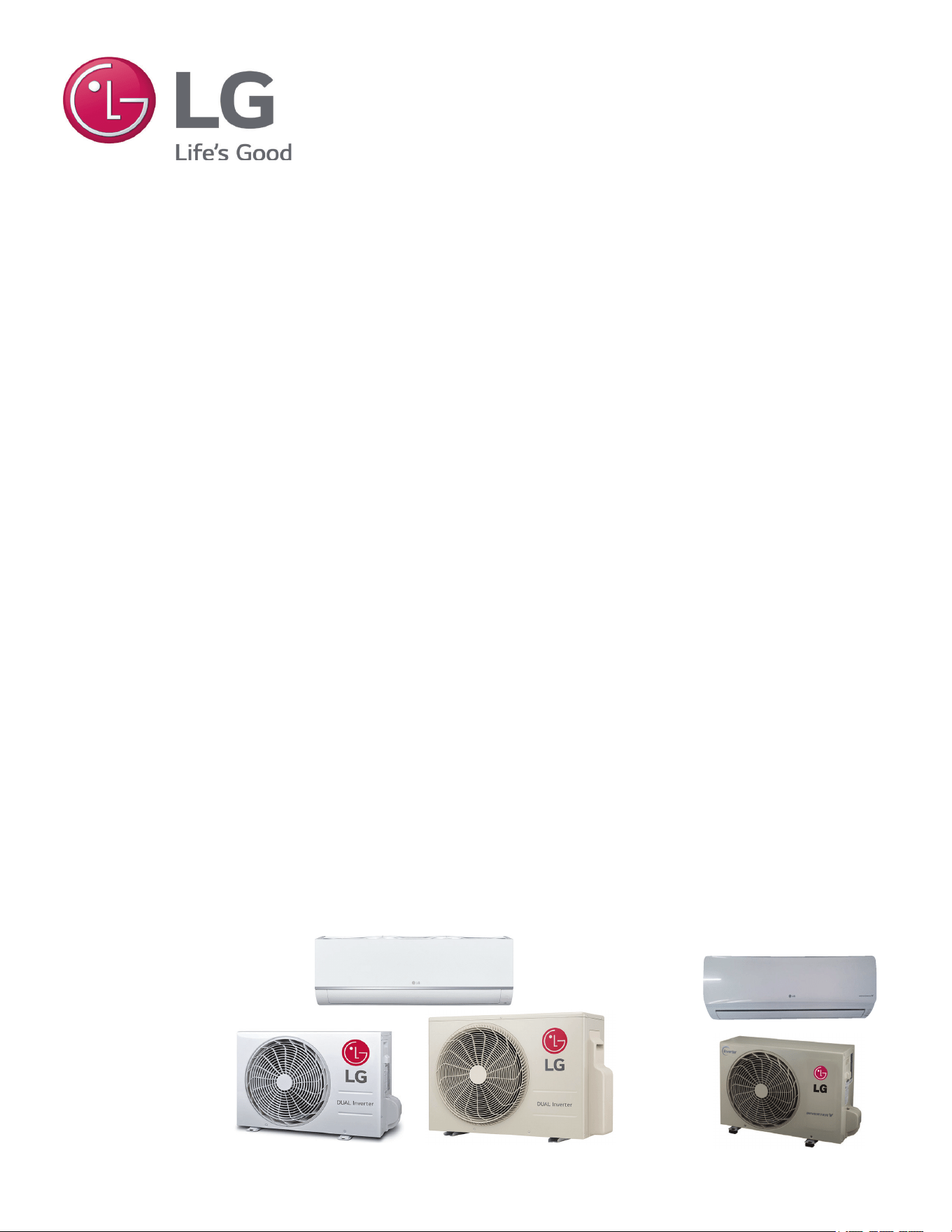
Single Zone Mega and Mega 115V
MECHANICAL SPECIFICATIONS
General
LG Single Zone Mega Wall Mounted systems
comprise of a single outdoor unit connected
to a single indoor unit with a single refriger-
ant circuit.
An LG Single Zone Mega Wall Mounted
system is a Duct-Free Split system that can
operate in either cooling or heating mode.
The system shall be capable of changing
mode within a maximum time of three (3)
minutes to ensure indoor temperature can be
properly maintained.
LG Single Zone Mega systems are manu-
factured in a facility registered to ISO 9001
and ISO 14001, which is a set of standards
applying to environmental protection set by
the International Organization for Standard-
ization (ISO). Wiring in these units are in
accordance with the National Electrical Code
(NEC).
Temperature Ranges
Mega (HEV2)
Operating ranges for outdoor unit of 14°F to
118°F (DB) for cooling; 14°F to 65°F (WB)
for heating.
Operating ranges for indoor unit of 53°F to
75°F (WB) for cooling; 60°F to 86°F (DB) for
heating.
Mega 115V (HXV)
Operating ranges for outdoor unit of 14°F to
118°F (DB) for cooling; 14°F to 65°F (WB)
for heating.
Operating ranges for indoor unit of 53°F to
75°F (WB) for cooling; 60°F to 86°F (DB) for
heating.
Casing / Frame
Outdoor unit is constructed with pre-coated
metal (PCM).
Indoor unit is constructed of heavy duty
Acrylonitrile Butadiene Styrene (ABS) and
High Impact Polystyrene (HIPS) plastic.
Refrigerant System
The refrigeration system consists of a single
refrigeration circuit and uses R410A refriger-
ant. The outdoor unit is provided with factory
installed components, including a refrigerant
strainer, check valves, oil separator, accu-
mulator, four-way reversing valve, EEV, high
and low side charging ports, service valves,
and interconnecting piping.
Refrigeration Oil Control
Heat Pump outdoor units have a centrifugal
oil separator and controls to ensure suf-
ficient oil supply is maintained, and that oil
does not travel with the refrigerant.
Compressors
The outdoor unit is equipped with one
hermetic, digitally controlled, inverter driven,
twin-rotary compressor to modulate capacity
(modulation in 1 Hz increments).
Frequency ranges for the (HEV2) outdoor
units are:
9k Btu/h = 10 to 92 Hz
12k Btu/h = 10 to 98 Hz
18 Btu/h = 10 to 87 Hz
24k Btu/h = 10 to 95 Hz
Frequency ranges for the (HXV) outdoor
units are:
9k Btu/h = 15 to 100 Hz
12k Btu/h = 15 to 100 Hz
Over-current protection and vibration isola-
tion are integrated with the compressor.
Outdoor Unit Coil
Heat Pump outdoor unit coils are of a
nonferrous construction with louvered fins
on copper tubing, and are protected with an
integral coil guard. Coil fins have a factory
applied corrosion resistant GoldFin™ mate-
rial with hydrophilic coating.
Fans and Motors
The outdoor unit includes one direct drive,
variable speed propeller type fan.
The Brushless Digitally Controlled (BLDC)
fan motor has inherent protection, perma-
nently lubricated bearings, and variable
speed with a maximum speed up to 950 rpm.
Raised guards are provided to limit contact
with moving parts.
The outdoor unit has horizontal discharge
airflow.
Electrical
The HEV2 model unit is available in a 208-
230V 60 Hz, 1-phase power supply. The
HXV model unit is available in a 115V 60
Hz, 1-phase power supply. The units are
capable of operating within voltage limits of
±10% rated voltage, and include overcurrent
protection.
Controls
The unit is factory wired with necessary elec-
trical control components, integral micropro-
cessors, printed circuit boards, thermistors,
sensors, terminal blocks, and lugs for power
wiring.
Microprocessor-based algorithms provide
component protection, soft-start capability,
refrigeration system pressure, temperature,
defrost, and ambient control.
PRODUCT DATA | 9
Product Data
'XHWRRXUSROLF\RIFRQWLQXRXVSURGXFWLQQRYDWLRQVRPHVSHFL¿FDWLRQVPD\FKDQJHZLWKRXWQRWL¿FDWLRQ
©
/*(OHFWURQLFV86$,QF(QJOHZRRG&OLIIV1-$OOULJKWVUHVHUYHG³/*´LVDUHJLVWHUHGWUDGHPDUNRI/*&RUS
GENERAL DATA
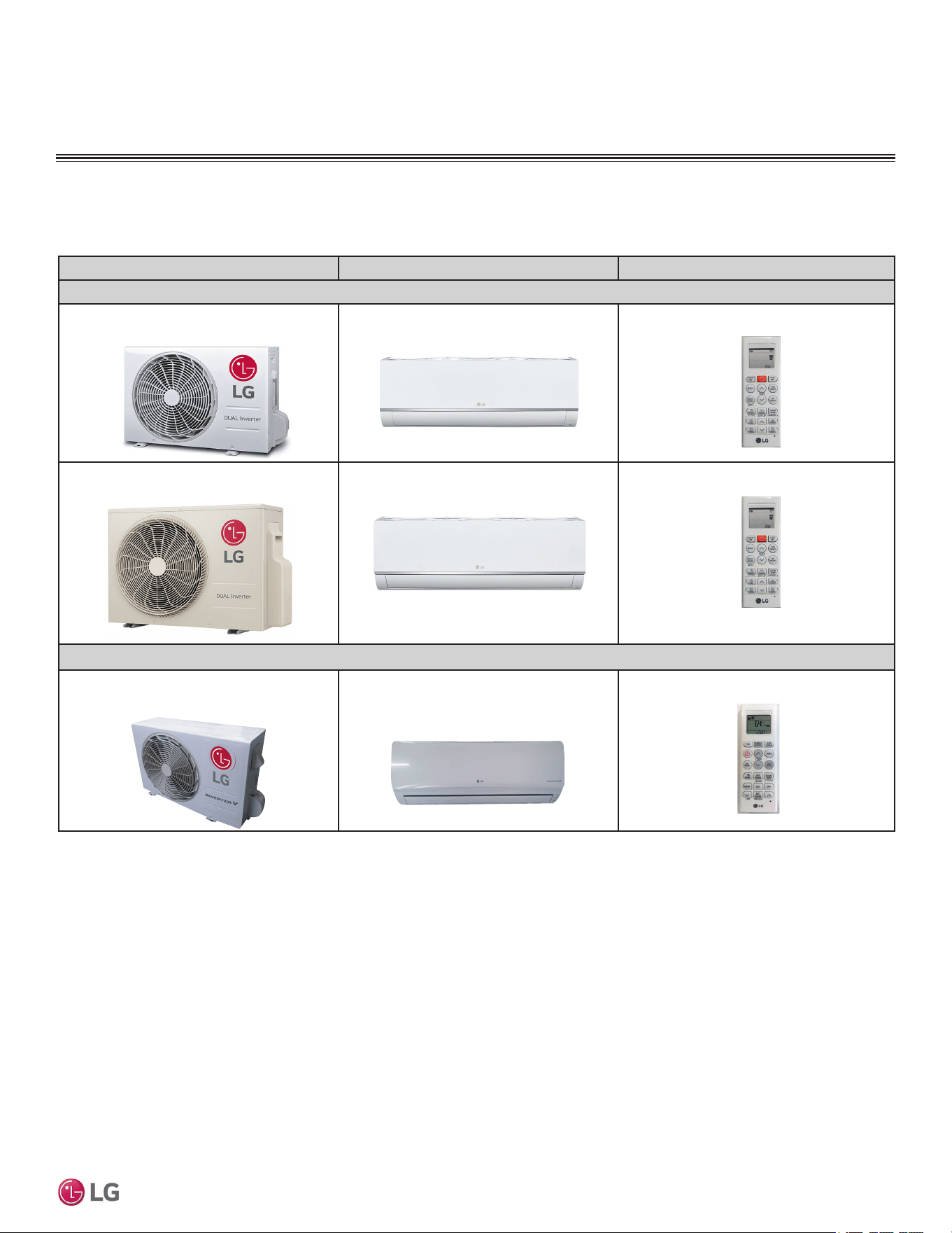
Mega Pairing Table
Outdoor Unit Model Indoor Unit Model Controller
Mega Inverter
LSU090HEV2
LSU120HEV2
LSN090HEV2
LSN120HEV2
AKB74955602
LSU180HEV2
LSU240HEV2
LSN180HEV2
LSN240HEV2
AKB74955602
Mega 115V
LSU090HXV
LSU120HXV
LSN090HXV
LSN120HXV
AKB73456121
Table 1: Single Zone Mega and Mega 115V Pairing Table
The following table shows the available outdoor and indoor unit, along with the factory provided controller.
10 | PRODUCT DATA
Single Zone Mega Wall Mounted Engineering Manual
'XHWRRXUSROLF\RIFRQWLQXRXVSURGXFWLQQRYDWLRQVRPHVSHFL¿FDWLRQVPD\FKDQJHZLWKRXWQRWL¿FDWLRQ
©
/*(OHFWURQLFV86$,QF(QJOHZRRG&OLIIV1-$OOULJKWVUHVHUYHG³/*´LVDUHJLVWHUHGWUDGHPDUNRI/*&RUS
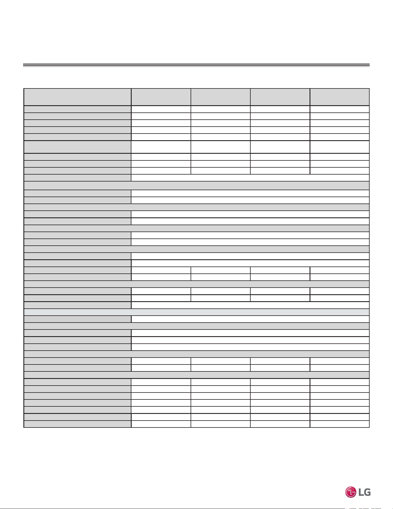
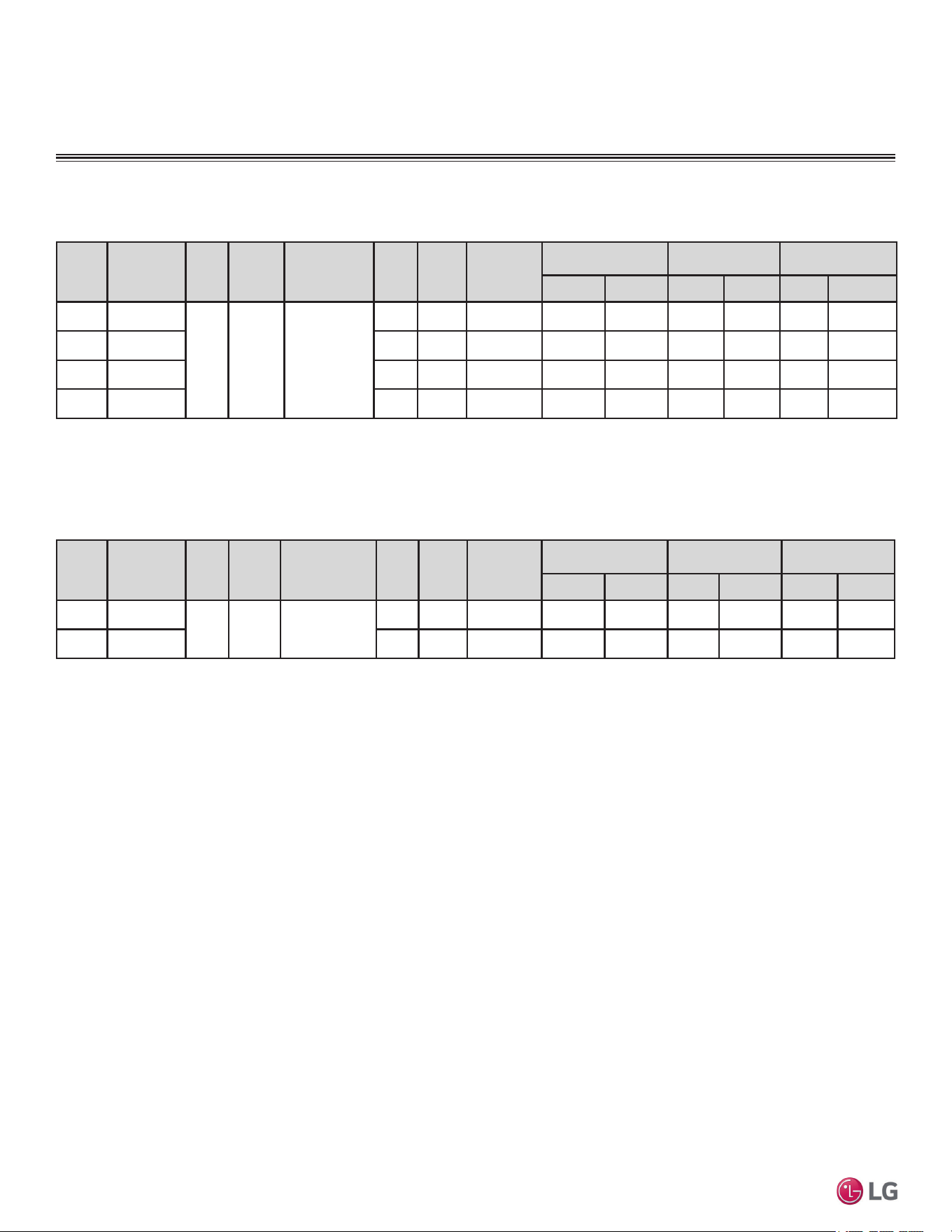
Table 2: 6LQJOH=RQH0HJD6\VWHP6SHFL¿FDWLRQV
GENERAL DATA
0HJD6SHFL¿FDWLRQV
System Model Number (IDU/ODU)
LS090HEV2
(LSN090HEV2/
LSU090HEV2)
LS120HEV2
(LSN120HEV2/
LSU120HEV2)
LS180HEV2
(LSN180HEV2/
LSU180HEV2)
LS240HEV2
(LSN240HEV2/
LSU240HEV2)
Cooling Capacity (Min/Rated/Max) (Btu/h)
3,070 ~ 9,000 ~10,330 3,070 ~ 12,000 ~ 13,780 3,685 ~ 18,000 ~ 18,493 3,685 ~ 22,000 ~ 24,000
Cooling Power Input
1
(kW)
0.72 1.142 1.5 2.0
Heating Capacity (Min/Rated/Max) (Btu/h)
3,070 ~ 10,900 ~ 12,520 3,070 ~ 12,000 ~ 13,780 3,685 ~ 19,000 ~ 22,997 3,685 ~ 22,000 ~25,260
Heating Power Input
1
(kW)
0.875 1.000 1.583 1.93
COP
12.46 12.00 12.00 11.40
Max. Heating Capacity (Btu/h)
Outdoor 17°F (WB)/Indoor 70°F (DB)
8,760 (80%) 9,640 (80%) 15,270 (80%) 17,680 (80%)
EER
12.5 10.51 12.00 11.00
SEER
20.0 19.0 19.0 19.0
HSPF
10.0 9.5 10.0 9.5
Power Supply (V/Hz/Ø)
208-230/60/1
Outdoor Unit Operating Range
Cooling (°F DB)
14 to 118
Heating (°F WB)
14 to 65
Indoor Unit Operating Range
Cooling (°F WB)
53 to 75
Heating (°F DB)
60 to 86
Indoor Temperature Setting Range
Cooling (°F)
64 to 86
Heating (°F)
60 to 86
Unit Data
Refrigerant Type
2
R410A
Refrigerant Control
EEV
IDU Sound Pressure
3
dB(A) (H/M/L/Sleep)
42 / 36 / 28 / 21 42 / 36 / 28 / 21 48 / 43 / 38 / 32 48 / 43 / 38 / 32
ODU Sound Pressure
3
dB(A)
50 50 55 55
Unit Weight (lbs)
IDU (Net / Shipping)
19.2 / 25.4 19.2 / 25.4 26 / 30 26 / 30
ODU (Net / Shipping)
55.3 / 60 55.3 / 60 98.1 / 108 98.1 / 108
Power/Communication Cable
4
(No. x AWG)
4 x 18
Compressor
Compressor Type (Qty)
Twin Rotary (1)
Fan
Indoor Unit Type (Qty)
Cross Flow (1)
Outdoor Unit Type (Qty)
Propeller (1)
Motor/Drive
Brushless Digital Controlled/Direct
Airflow Rate
Indoor Unit Max/H/M/L (CFM)
459 / 353 / 264 / 148 459 / 353 / 264 / 148 689 / 512 / 459 / 371 689 / 512 / 459 / 371
Outdoor Unit (Max. [CFM])
953 953 1,730 1,730
Piping
Liquid Line (in, OD)
1/4 1/4 1/4 1/4
Vapor Line (in, OD)
3/8 3/8 1/2 1/2
Condensation Line (OD, ID)
27/32, 5/8 27/32, 5/8 27/32, 5/8 27/32, 5/8
Additional Refrigerant Charge (oz/ft)
0.22 0.22 0.26 0.26
Pipe Length
5
(Minimum/Maximum)(ft)
9.8 / 49.2 9.8 / 49.2 9.8 / 65.6 9.8 / 65.6
Piping Length
5
(no add’l refrigerant, ft)
24.6 24.6 24.6 24.6
Max Elevation Difference (ft)
23 23 32.8 32.8
EEV: Electronic Expansion Valve IDU: Indoor Unit ODU: Outdoor Unit
This unit comes with a dry helium charge.
This data is rated 0 ft above sea level with 24.6 of refrigerant line per indoor unit and a 0 ft level
difference outdoor and indoor units.
Cooling capacity rating obtained with air entering the indoor unit at 80ºF dry bulb (DB) and 67ºF wet
bulb (WB) and outdoor ambient conditions of 95ºF dry bulb (DB) and 75ºF wet bulb (WB).
Heating capacity rating obtained with air entering the indoor unit at 70ºF dry bulb (DB) and 59ºF wet
bulb (WB) and outdoor ambient conditions of 47ºF dry bulb (DB) and 43ºF wet bulb (WB).
1
Power Input is rated at high speed.
2
Take appropriate actions at the end of HVAC equipment life to recover, recycle, reclaim or destroy R410A
refrigerant according to applicable regulations (40 CFR Part 82, Subpart F) under section 608 of CAA.
3
Sound Pressure levels are tested in an anechoic chamber under ISO Standard 3745.
4
All communication / connection (power) cable from the outdoor unit to the indoor unit is field supplied
and must be a minimum of four-conductor, 18 AWG, stranded, shielded or unshielded (if shielded, it
must be grounded to the chassis of the outdoor unit only), and must comply with applicable local and
national codes. For detailed electrical information, please refer to electric characteristics on page 18.
5
Piping lengths are equivalent.
PRODUCT DATA | 11
Product Data
'XHWRRXUSROLF\RIFRQWLQXRXVSURGXFWLQQRYDWLRQVRPHVSHFL¿FDWLRQVPD\FKDQJHZLWKRXWQRWL¿FDWLRQ
©
/*(OHFWURQLFV86$,QF(QJOHZRRG&OLIIV1-$OOULJKWVUHVHUYHG³/*´LVDUHJLVWHUHGWUDGHPDUNRI/*&RUS
GENERAL DATA
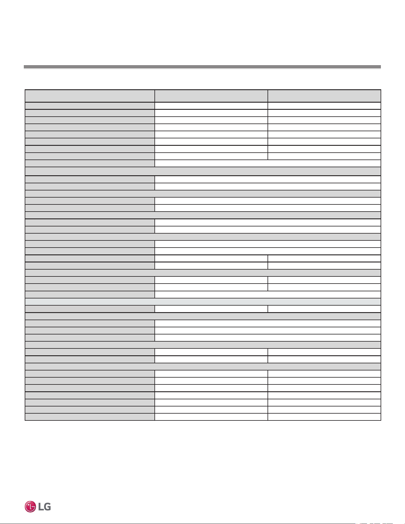
0HJD96SHFL¿FDWLRQV
Table 3: 6LQJOH=RQH0HJD96\VWHP6SHFL¿FDWLRQV
System Model Number (IDU/ODU) LS090HXV (LSN090HXV/LSU090HXV) LS120HXV (LSN120HXV/LSU120HXV)
Cooling Capacity (Min/Rated/Max) (Btu/h)
1,023 ~ 8,500 ~ 13,785 1,023 ~ 12,000 ~ 13,785
Cooling Power Input
1
(kW)
0.71 1.14
Heating Capacity (Min/Rated/Max) (Btu/h)
1,023 ~ 10,900 ~ 22,178 1,023 ~ 13,000 ~ 22,178
Heating Power Input
1
(kW)
0.88 1.09
COP
3.63 3.50
EER
12.01 10.5
SEER
17.0 17.0
HSPF
9.0 9.0
Power Supply (V/Hz/Ø)
115/60/1
Outdoor Unit Operating Range
Cooling (°F DB)
14 to 118
Heating (°F WB)
14 to 65
Indoor Unit Operating Range
Cooling (°F WB)
53 to 75
Heating (°F DB)
60 to 86
Indoor Temperature Setting Range
Cooling (°F)
65 to 86
Heating (°F)
60 to 86
Unit Data
Refrigerant Type
2
R410A
Refrigerant Control
EEV
IDU Sound Pressure
3
dB(A) (H/M/L/Sleep)
39/33/23/19 39/33/23/19
ODU Sound Pressure
3
dB(A)
47 47
Unit Weight (lbs)
IDU (Net/Shipping)
23/26 23/26
ODU (Net/Shipping)
67/79 67/79
Power/Communication Cable
4
(No. x AWG)
4 x 18
Compressor
Compressor Type (Qty)
Single Rotary (1) Single Rotary (1)
Fan
IDU Type (Qty)
Cross Flow (1)
ODU Type (Qty)
Propeller (1)
Motor/Drive
Brushless Digitally Controlled/Direct
Airflow Rate
IDU Max/H/M/L (CFM)
335/272/212/124 335/272/212/124
ODU Max (CFM)
1,000 1,000
Piping
Liquid Line (in, OD)
1/4 1/4
Vapor Line (in, OD)
3/8 3/8
Condensation Line (OD, ID)
27/32, 5/8 27/32, 5/8
Additional Refrigerant Charge (oz/ft)
0.22 0.22
Pipe Length
5
(Minimum/Maximum)(ft)
6.6 / 49.2 6.6 / 49.2
Piping Length
5
(no add’l refrigerant, ft)
24.6 24.6
Max Elevation Difference (ft)
23 23
EEV: Electronic Expansion Valve IDU: Indoor Unit ODU: Outdoor Unit
This unit comes with a dry helium charge.
This data is rated 0 ft above sea level with 24.6 of refrigerant line per indoor unit and a 0 ft level
difference outdoor and indoor units.
Cooling capacity rating obtained with air entering the indoor unit at 80ºF dry bulb (DB) and 67ºF wet
bulb (WB) and outdoor ambient conditions of 95ºF dry bulb (DB) and 75ºF wet bulb (WB).
Heating capacity rating obtained with air entering the indoor unit at 70ºF dry bulb (DB) and 59ºF wet
bulb (WB) and outdoor ambient conditions of 47ºF dry bulb (DB) and 43ºF wet bulb (WB).
1
Power Input is rated at high speed.
2
Take appropriate actions at the end of HVAC equipment life to recover, recycle, reclaim or destroy R410A
refrigerant according to applicable regulations (40 CFR Part 82, Subpart F) under section 608 of CAA.
3
Sound Pressure levels are tested in an anechoic chamber under ISO Standard 3745.
4
All communication / connection (power) cable from the outdoor unit to the indoor unit is field supplied
and must be a minimum of four-conductor, 18 AWG, stranded, shielded or unshielded (if shielded, it
must be grounded to the chassis of the outdoor unit only), and must comply with applicable local and
national codes. For detailed electrical information, please refer to electric characteristics on page 18.
5
Piping lengths are equivalent.
12 | PRODUCT DATA
Single Zone Mega Wall Mounted Engineering Manual
'XHWRRXUSROLF\RIFRQWLQXRXVSURGXFWLQQRYDWLRQVRPHVSHFL¿FDWLRQVPD\FKDQJHZLWKRXWQRWL¿FDWLRQ
©
/*(OHFWURQLFV86$,QF(QJOHZRRG&OLIIV1-$OOULJKWVUHVHUYHG³/*´LVDUHJLVWHUHGWUDGHPDUNRI/*&RUS
Nominal
Tons
Unit Model
No.
Hertz Voltage
Voltage Range
(Min. to Max.)
MCA MOP
Compressor
Quantity
Compressor Motor
RLA
Outdoor Fan Motor Indoor Fan Motor
Cooling Heating W FLA W FLA
3/4 LS090HEV2
60 208 - 230 187-253
10.0 15 1 7.0 7.0 43 0.4 30 0.4
1 LS120HEV2 10.0 15 1 7.0 7.0 43 0.4 30 0.4
1-1/2 LS180HEV2 15.0 20 1 10.0 10.0 85 0.4 58 0.4
2 LS240HEV2 15.0 20 1 10.0 10.0 85 0.4 58 0.4
0HJDDQG0HJD92XWGRRU8QLWV
ELECTRICAL DATA
Table 4: 208-230V, 60Hz, 1-Phase Single-Zone Mega System Electrical Data Table.
Table 5: 115V, 60Hz, 1-Phase Single Zone Single-Zone Mega 115V System Electrical Data Table.
Nominal
Tons
Unit Model
No.
Hertz Voltage
Voltage Range
(Min. to Max.)
MCA MOP
Compressor
Quantity
Compressor Motor
RLA
Outdoor Fan Motor Indoor Fan Motor
Cooling Heating W FLA W FLA
3/4 LS090HXV
60 115 104-127
13.5 20 1 10.0 10.0 43 0.4 30 0.5
1 LS120HXV 13.5 20 1 10.0 10.0 43 0.4 30 0.5
Electrical Data
Voltage tolerance is ±10%.
Maximum allowable voltage unbalance is 2%.
MCA = Minimum Circuit Ampacity.
Maximum Overcurrent Protection (MOP) is calculated as follows: (Largest motor FLA x 2.25) + (Sum of
other motor FLA) rounded down to the nearest standard fuse size.
RLA = Rated Load Amps.
FLA = Full Load Amps.
PRODUCT DATA | 13
Product Data
'XHWRRXUSROLF\RIFRQWLQXRXVSURGXFWLQQRYDWLRQVRPHVSHFL¿FDWLRQVPD\FKDQJHZLWKRXWQRWL¿FDWLRQ
©
/*(OHFWURQLFV86$,QF(QJOHZRRG&OLIIV1-$OOULJKWVUHVHUYHG³/*´LVDUHJLVWHUHGWUDGHPDUNRI/*&RUS
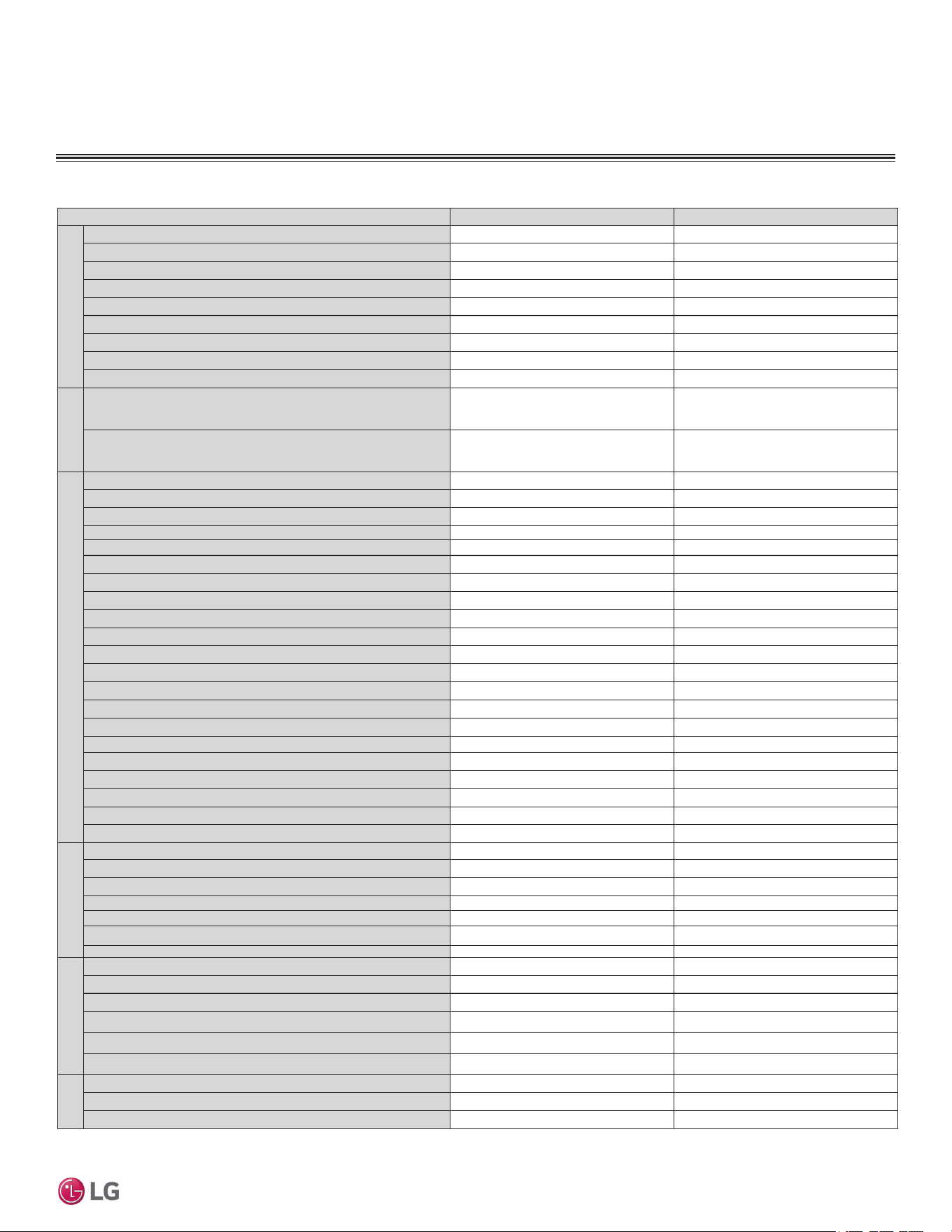
FUNCTIONS, CONTROLS, OPTIONS
Table 6: Indoor Units—Functions, Controls and Options.
Indoor Unit Type LS090-120-180-240HEV2 LS090-120HXV
$LUÀRZ
Air Supply Outlet
11
Airflow Direction Control (Left / Right)
Manual Auto
Airflow Direction Control (Up / Down)
Auto Auto
Auto Swing (Left / Right)
X ¥
Auto Swing (Up / Down)
¥¥
Fan Speed Airflow Steps (Fan / Cool / Heat)
6 / 6 / 6 6 / 6 / 6
Natural Wind (Auto Wind)
¥¥
Jet Cool / Jet Heat (Power Wind)
¥¥ ¥¥
Comfort Air
¥ X
Air Purifying
Prefilter (Washable Anti-Bacterial / Anti-Fungal
1
)
¥¥
Deodorizing Filter
XX
Functions
Drain Pump
XX
Hot Start
¥¥
Self Diagnostics
¥¥
Defrost
¥¥
Dry (Dehumidification)
¥¥
Auto Changeover
¥¥
Auto Cleaning (Coil Dry)
¥¥
Auto Restart
¥ ¥
Child Lock
XX
Forced Operation
¥¥
Sleep Mode
¥KRXU ¥
Timer 24 hour (On / Off) / 7 hour (Off)
¥; ¥
Timer (Weekly)
XX
Two Thermistor Control
XX
Low Ambient
¥ ¥
Overheat Protection
¥¥
Smart Diagnosis
¥ X
Indoor Unit Display Type
Number Display 3 LED
Indoor Unit Display Light
On / Off On / Off
Energy Saving
¥¥
Electric heater
XX
Controllers
Wireless Remote Controller
AKB74955602 AKB73456121
Simple Controller
Xo
Programmable Controller
Xo
Premium Programmable Controller
Xo
Dry contact
Xo
Central control (LGAP)
XX
PI 485
XX
Special Function Kit
Zone control
XX
CTIE
XX
Electro thermostat
XX
Wi-Fi Module (Option)
XX
Water level sensor connection (for optional AG-9300-LG)
oo
Wind baffle kit
XX
Other
Mode Lock
Cooling Only or Heating Only X
Temperature Control
Thermistor X
Smart Inverter Monitoring System (SIMS)
¥¥
1
Primary washable filters. ¥ 6WDQGDUGIHDWXUH
o = Optional accessory (must be purchased separately)
X = Not available
14 | PRODUCT DATA
Single Zone Mega Wall Mounted Engineering Manual
'XHWRRXUSROLF\RIFRQWLQXRXVSURGXFWLQQRYDWLRQVRPHVSHFL¿FDWLRQVPD\FKDQJHZLWKRXWQRWL¿FDWLRQ
©
/*(OHFWURQLFV86$,QF(QJOHZRRG&OLIIV1-$OOULJKWVUHVHUYHG³/*´LVDUHJLVWHUHGWUDGHPDUNRI/*&RUS
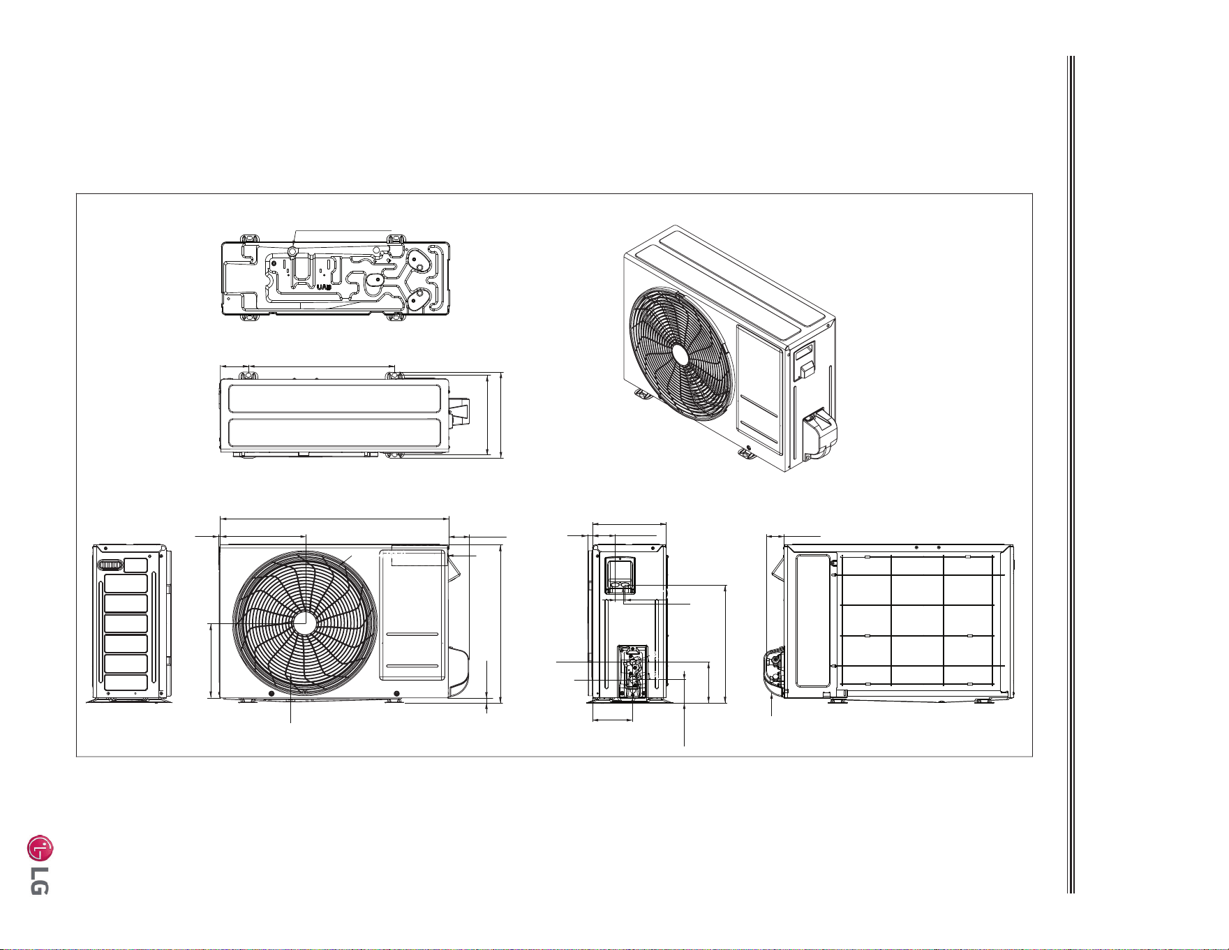
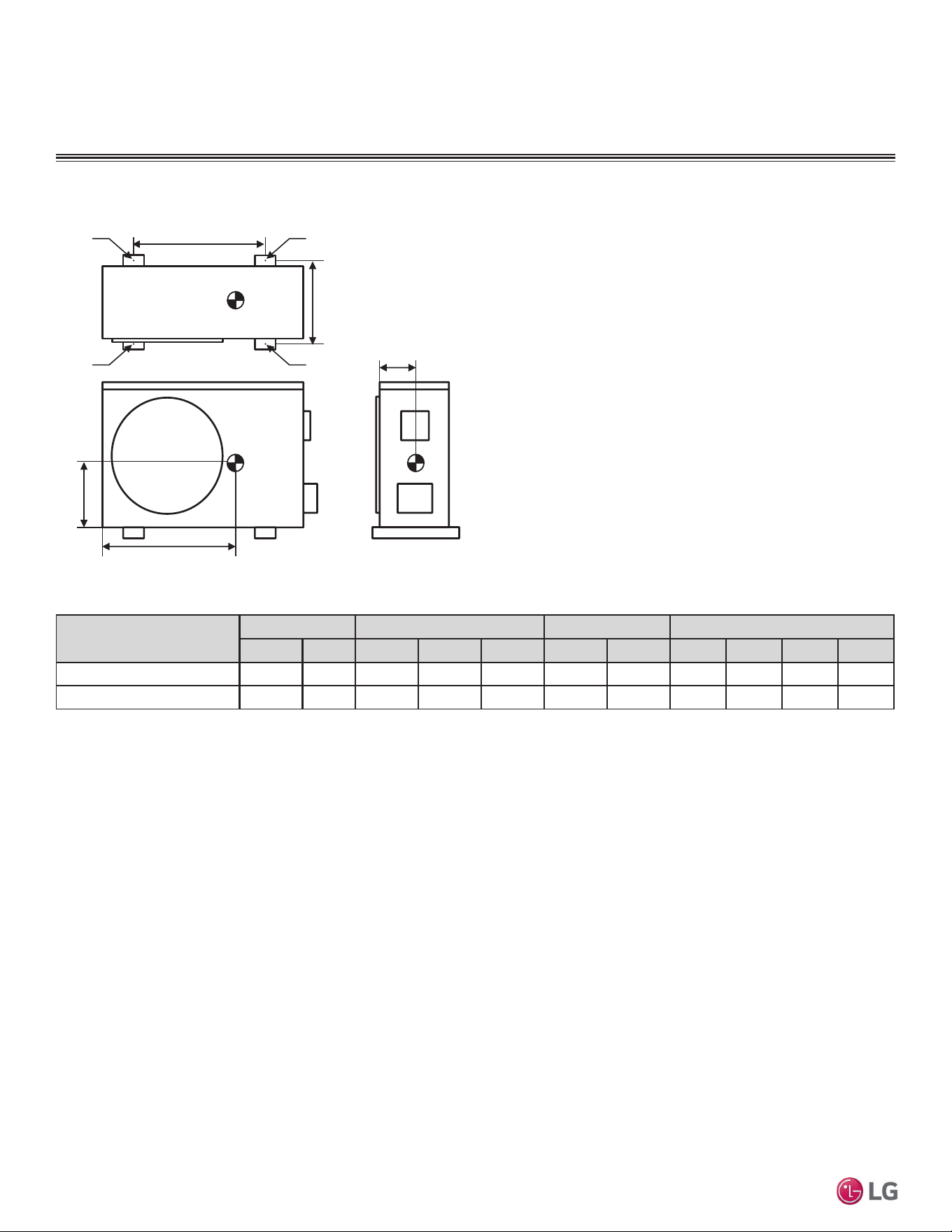
OUTDOOR UNIT DIMENSIONS
LSU090HEV2, LSU120HEV2
Unit: Inch (mm)
9-27/32 (250)
10-5/8 (270)
Drain Hole 2-Ø13/16 (20)
3-1/2 (89)
18-7/32 (463)
5/8 (16)
2-9/16 (65)
28-7/32 (717)
10-1/2 (267)3/16 (5)
19-1/2 (495)
9/16 (14)
9-1/4 (235)
2-7/32 (56)
Ø16-1/4 (413)
9-1/16 (230)
2-13/16 (71)
14-5/8 (371)
5-3/32 (129)
2-15/16 (74)
5 (127)
1-1/4 (31)
21°
21°
Liquid Pipe
Connection
(Flare)
Vapor Pipe
Connection
(Flare)
Service Valve Cover
Power
and
Communication
Cable
Access
Hole
Air Outlet
Control
Box
PRODUCT DATA | 15
Product Data
'XHWRRXUSROLF\RIFRQWLQXRXVSURGXFWLQQRYDWLRQVRPHVSHFL¿FDWLRQVPD\FKDQJHZLWKRXWQRWL¿FDWLRQ
©
/*(OHFWURQLFV86$,QF(QJOHZRRG&OLIIV1-$OOULJKWVUHVHUYHG³/*´LVDUHJLVWHUHGWUDGHPDUNRI/*&RUS
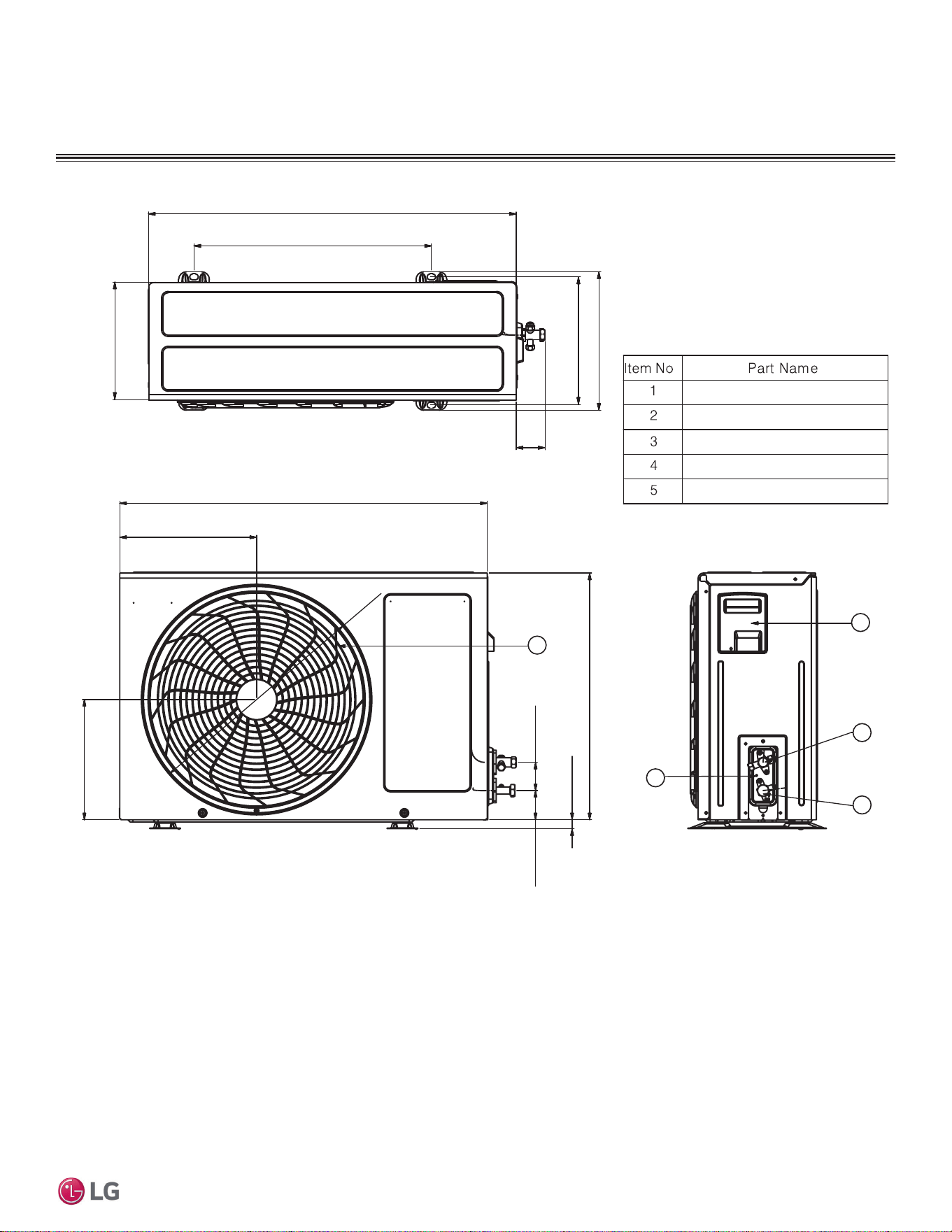
LSU180HEV2, LSU240HEV2
OUTDOOR UNIT DIMENSIONS
Unit: Inch (mm)
5-5/8 (143) 23-1/16 (586)
14-13/32 (366)
15-3/16 (386)
1-1/32 (26)
12-5/16 (313)
12-11/16 (322)
34-1/4 (870)
20-9/32 (515)
3-1/16 (78)
1-1/4 (32)
13 (330)
6-17/32 (166)
4-19/32 (117)
6-25/32 (172)
7-9/16 (192)
3/4 (19)
2-1/16 (52)
25-19/32 (650)
7/8 (22)
25°25°
25°25°
Liquid Pipe
Connection
(Flare)
Vapor Pipe
Connection
(Flare)
Service Valve
Cover
Power and
Communication
Cable Access
Hole
Control Box
Air Outlet
Drain Hole 2-
Ø13/16 (20)
16 | PRODUCT DATA
Single Zone Mega Wall Mounted Engineering Manual
'XHWRRXUSROLF\RIFRQWLQXRXVSURGXFWLQQRYDWLRQVRPHVSHFL¿FDWLRQVPD\FKDQJHZLWKRXWQRWL¿FDWLRQ
©
/*(OHFWURQLFV86$,QF(QJOHZRRG&OLIIV1-$OOULJKWVUHVHUYHG³/*´LVDUHJLVWHUHGWUDGHPDUNRI/*&RUS
OUTDOOR UNIT CORNER WEIGHT AND CENTER OF
GRAVITY DIMENSIONS
Figure 3: LSU090-120-180-240HEV2 Outdoor Unit Corner Weight and Center of Gravity Dimensions.
e
a
b
c
A
d
B
C
D
Model No.
Weight (lb.) Center of Gravity (Inch) Leg (Inch) Corner Weight (lb.)
Shipping Net a b c d e A B C D
LSU090HEV2, LSU120HEV2 60.0 55.3 18-11/16 8-5/8 4-7/16 18-7/32 10-3/32 3.5 5.7 23.1 23.0
LSU180HEV2, LSU240HEV2 108.0 98.1 22-1/4 10-1/4 5-29/32 23-1/16 14-13/32 11.4 16.0 37.3 33.4
Table 7: LSU090-120-180-240HEV2 Outdoor Unit Corner Weight and Center of Gravity Dimensions.
PRODUCT DATA | 17
Product Data
'XHWRRXUSROLF\RIFRQWLQXRXVSURGXFWLQQRYDWLRQVRPHVSHFL¿FDWLRQVPD\FKDQJHZLWKRXWQRWL¿FDWLRQ
©
/*(OHFWURQLFV86$,QF(QJOHZRRG&OLIIV1-$OOULJKWVUHVHUYHG³/*´LVDUHJLVWHUHGWUDGHPDUNRI/*&RUS
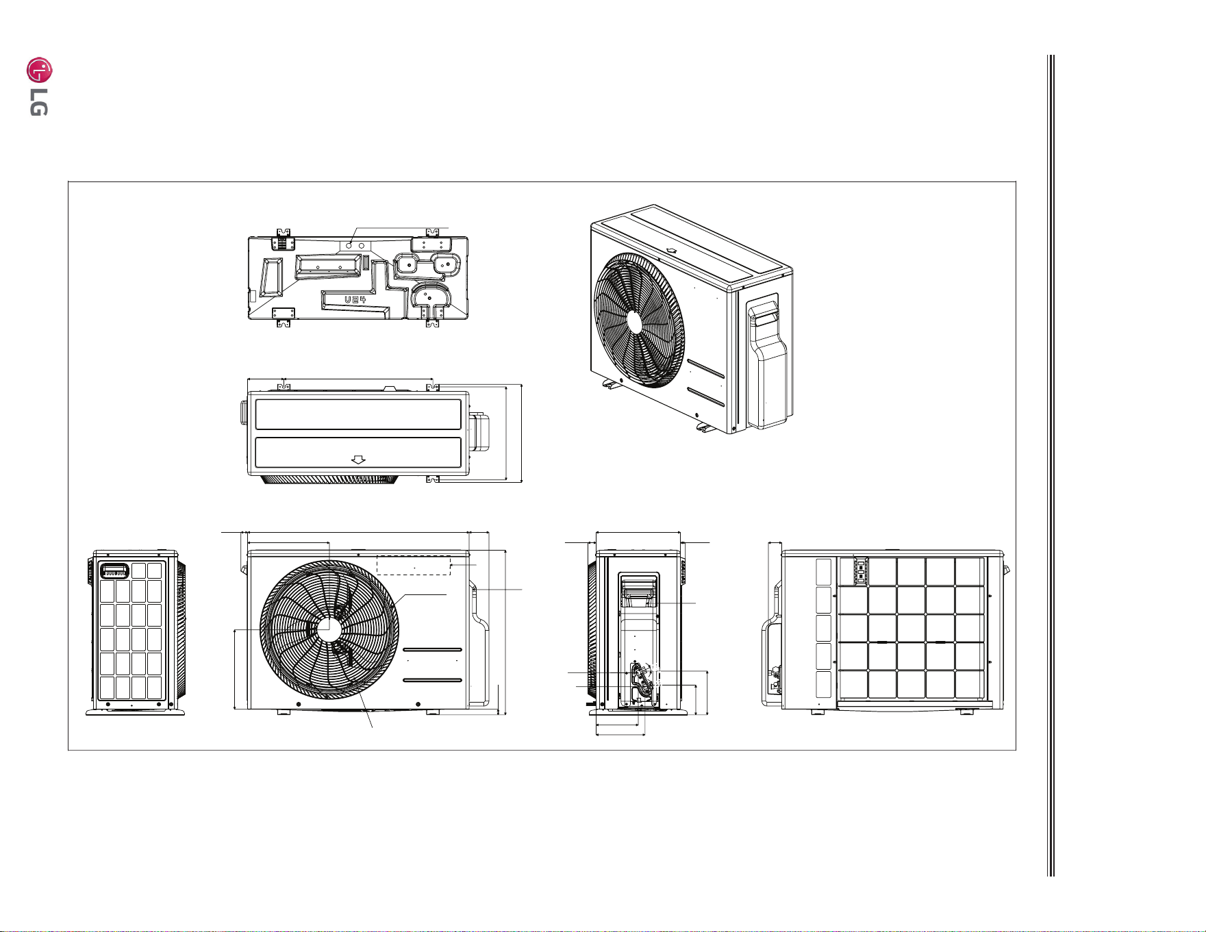
OUTDOOR UNIT DIMENSIONS
LSU090HXV, LSU120HXV
5
4
2
3
28-1/4
Ø17-3/8
10-9/16
9-5/16
19-1/2
2-3/16
2-1/4
7/16
1
Unit: Inch
.
18-1/4
28-1/4
2-1/4
10 -1/16
9-1/16
10-11/16
Discharge Air Grille
Gas Pipe Connection Port
Liquid Pipe Connection Port
Control Box
Ground Terminal
18 | PRODUCT DATA
Single Zone Mega Wall Mounted Engineering Manual
'XHWRRXUSROLF\RIFRQWLQXRXVSURGXFWLQQRYDWLRQVRPHVSHFL¿FDWLRQVPD\FKDQJHZLWKRXWQRWL¿FDWLRQ
©
/*(OHFWURQLFV86$,QF(QJOHZRRG&OLIIV1-$OOULJKWVUHVHUYHG³/*´LVDUHJLVWHUHGWUDGHPDUNRI/*&RUS
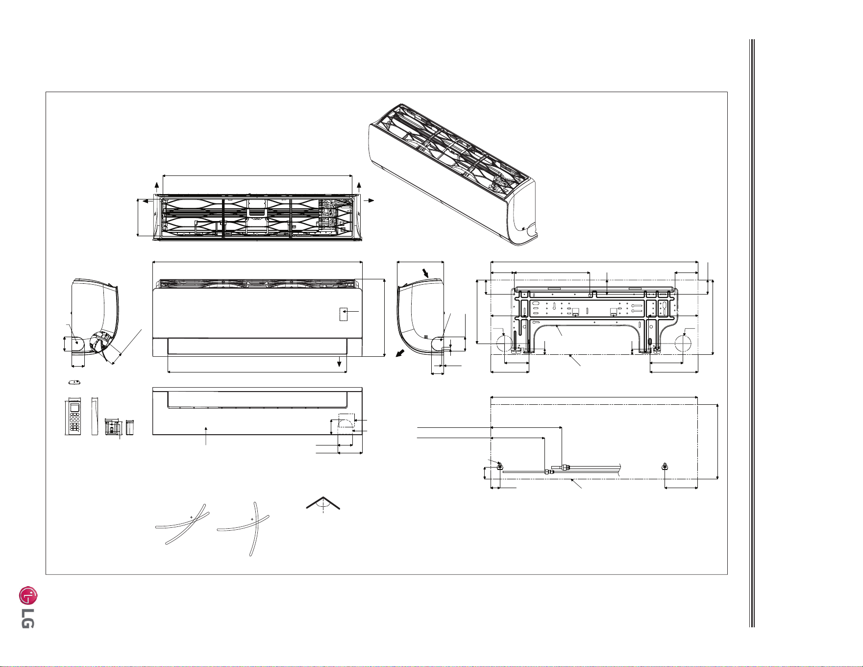
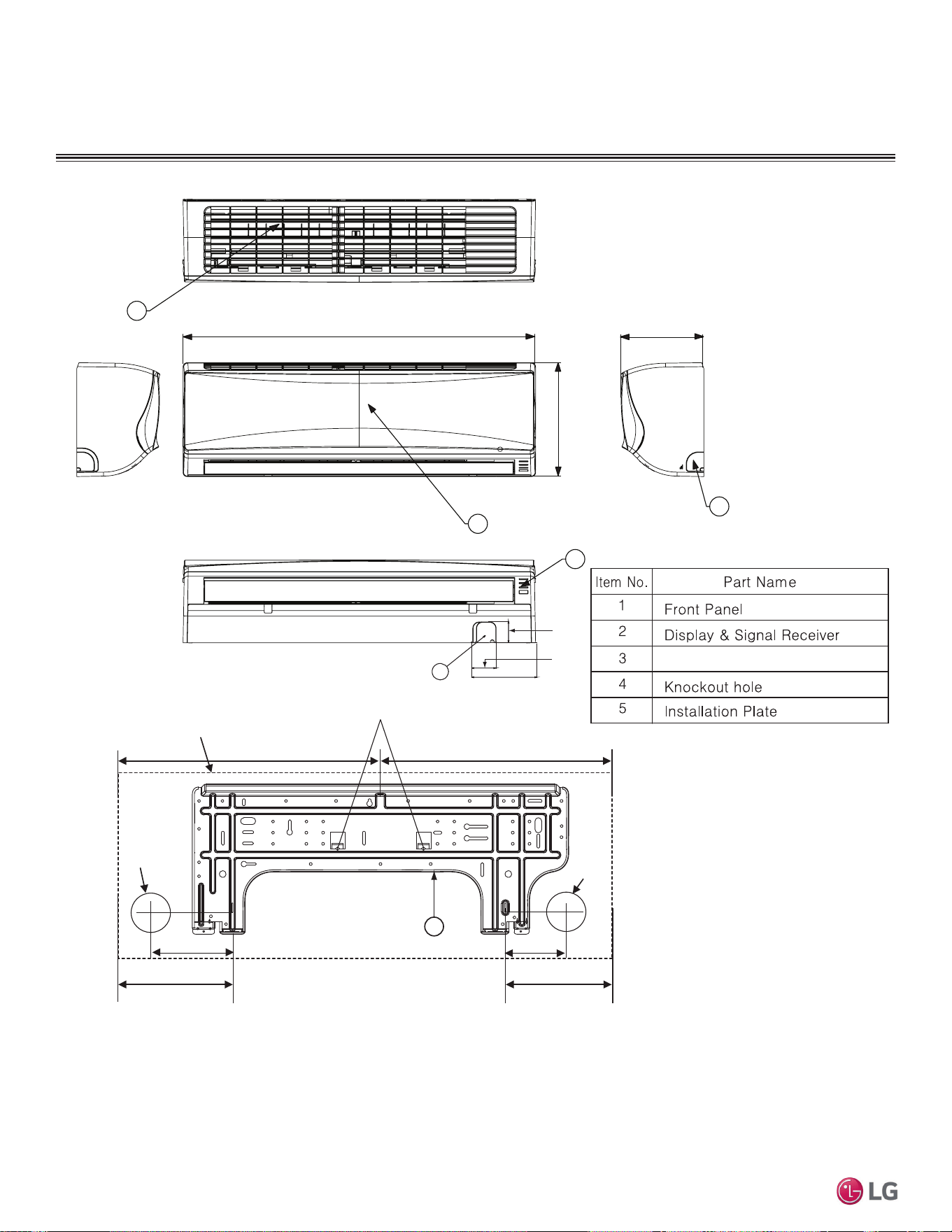
INDOOR UNIT DIMENSIONS
LSN090HEV2, LSN120HEV2
Unit : Inch (mm)
[30-3/16 (767)]
32-15/16 (837)
3-5/8 (92)
2-3/8 (60)
2-5/16
(59)
12-1/8 (308)
7-7/16 (189)
32-15/16 (837)
1-1/2 (38)
Approx. 11-11/32 (288) to gas pipe
Approx. 8-19/32 (218) to liquid pipe
1-27/32(47)
5-3/16 (132)
In Case of Left Side Piping
Unit Outline
Connecting Gas/Liquid Pipe
12-1/8 (308)
Decoration Cover
Display
and
Remote
Controller
Signal
Receiver
Terminal Block
for Power
Supply and
Communication
Drain Hose Connection
2-7/32(56)
11/32 (9)
Installation Plate
Knock-Out
Refrigerant,
Drain Pipe
and Cable
Routing Hole
5/16 (8)
2 (51)
Air Intake
Air Outlet
Bottom
28-5/32 (715)
Air Outlet Hole
* If airflow direction control is available,
Cooling Heating
Up & Down Left & Right
Air Outlet Hole
Air Intake Hole
[5-29/32 (150)]
Air Intake Hole
Rear
Rear
Right
Left
55°
15°
15°
85°
45°
55°
32-15/16 (837)
2-15/32
(63)
12-1/16 (306)
3-21/32 (93)
10-11/32 (263)
5-31/32 (152)
3-27/32 (98)
5-9/32 (134)
12-1/8 (308)
3-11/16 (94)
7-5/8 (194)
Unit Outline
Fixing the Installation Plate, Drilling Hole
29/32 (23)
Ø2-9/16 (65)
1-3/32 (50.2)
1-1/16 (26.2)
2-7/16 (61.5)
1-7/16(33.5)
1/4(6) x 1/8(3)
1/8(3) x 1/4(6)
5/8(15.3)
1-9/32(32.7)
2-13/32(61)
5-31/32 (152)
1-1/4 (31)
2-7/32 (56)
2 (51)
2-7/32 (56)
5-19/32 (142)
Ø2-9/16 (65)
7-27/32 (199)
29/32 (23)
2-15/32 (63)
2-17/32 (64)
Knock-Out
Refrigerant,
Drain Pipe
and Cable
Routing Hole
Knock-Out
Refrigerant,
Drain Pipe
and Cable
Routing Hole
PRODUCT DATA | 19
Product Data
'XHWRRXUSROLF\RIFRQWLQXRXVSURGXFWLQQRYDWLRQVRPHVSHFL¿FDWLRQVPD\FKDQJHZLWKRXWQRWL¿FDWLRQ
©
/*(OHFWURQLFV86$,QF(QJOHZRRG&OLIIV1-$OOULJKWVUHVHUYHG³/*´LVDUHJLVWHUHGWUDGHPDUNRI/*&RUS
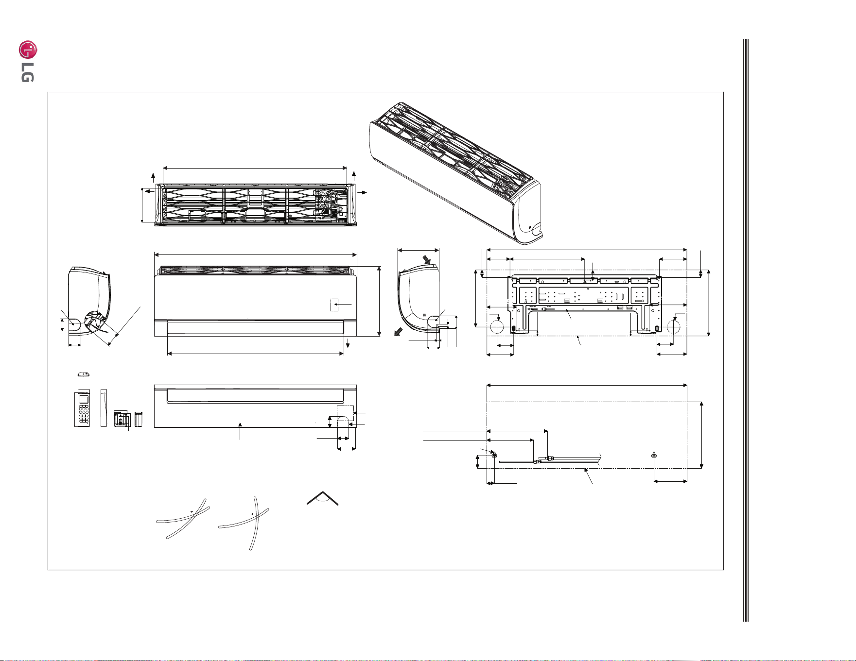
INDOOR UNIT DIMENSIONS
LSN180HEV2, LSN240HEV2
Unit : Inch (mm)
[36-5/32 (918)]
Air Intake Hole
[6-11/16 (170)]
Air Intake Hole
ir Outlet Ho
[2-29/32 (74)]
Ale
Rear
39-9/32 (998)
2-1/4 (57)
2-7/32 (56)
3-17/32 (90)
Bottom
Air
Outlet
34-11/32 (872)
Air Outlet Hole
13-19/32 (345)
2-3/8 (60)
7/16(11)
Air Intake
8-9/32 (210)
13-19/32 (345)
39-9/32 (998)
6-15/32 (164)
1-15/32 (37)
2-15/32 (63)
In case of Left Side Piping
Unit Outline
Approx. 9-7/16 (240) to gas pipe
Approx. 6-5/16 (160) to liquid pipe
Connecting Gas/Liquid Pipe
2-3/8 (60)
2-3/8 (60)
Rear
Left
Right
Decoration Cover
Drain Hose Connection
Installation Plate
If airflow direction control is available,*
Cooling Heating
Up & Down Left & Right
50°
15°
20°
85°
45°
50°
39-9/32 (998)
2-23/32 (69)
14-11/16 (373)
5-13/32 (137)
2-3/32 (53)
13-19/32 (345)
Ø2-9/16 (65)
3-9/32 (83)
Unit Outline
Fixing the Installation Plate, Drilling Hole
1-1/16 (27)
5-29/32 (150)
4-17/32 (115)
Ø2-9/16 (65)
3-9/32 (83)
5-9/32 (134)
1-1/16 (27)
2-3/32 (53)
11-13/16 (300)
7/16 (11)
1-3/32 (50.2)
1-1/16 (26.2)
2-7/16 (61.5)
1-7/16(33.5)
1/4(6) x 1/8(3)
1/8(3) x 1/4(6)
5/8(15.3)
1-9/32(32.7)
2-13/32(61)
5-31/32 (152)
1-1/4 (31)
2-3/8 (60)
5-29/32 (150)
7-13/32 (188)
Display
and
Remote
Controller
Signal
Receiver
Terminal Block
for Power
Supply and
Communication
Knock-Out
Refrigerant,
Drain Pipe
and Cable
Routing Hole
Knock-Out
Refrigerant,
Drain Pipe
and Cable
Routing Hole
Knock-Out
Refrigerant,
Drain Pipe
and Cable
Routing Hole
20 | PRODUCT DATA
Single Zone Mega Wall Mounted Engineering Manual
'XHWRRXUSROLF\RIFRQWLQXRXVSURGXFWLQQRYDWLRQVRPHVSHFL¿FDWLRQVPD\FKDQJHZLWKRXWQRWL¿FDWLRQ
©
/*(OHFWURQLFV86$,QF(QJOHZRRG&OLIIV1-$OOULJKWVUHVHUYHG³/*´LVDUHJLVWHUHGWUDGHPDUNRI/*&RUS
INDOOR UNIT DIMENSIONS
LSN090HXV, LSN120HXV
34-7/8
8-5/16
11 -1/4
3
2
4
1
Ø
2-13/16
5-1/4
3-3/4
Right rear
piping
Left rear
piping
Installation Plate
Place a level on raised tab
Unit Outline
8-9/16
6-15/16
17-7/16 17-7/16
5
Ø
2-13/16
4
2-5/16
6-5/16
15/16
Unit: Inch
Return Air
G
rill
e
for piping and cable
PRODUCT DATA | 21
Product Data
'XHWRRXUSROLF\RIFRQWLQXRXVSURGXFWLQQRYDWLRQVRPHVSHFL¿FDWLRQVPD\FKDQJHZLWKRXWQRWL¿FDWLRQ
©
/*(OHFWURQLFV86$,QF(QJOHZRRG&OLIIV1-$OOULJKWVUHVHUYHG³/*´LVDUHJLVWHUHGWUDGHPDUNRI/*&RUS
Figure 4: Mega Indoor Unit Sound Level Measurement.
Model
Sound Pressure Levels (dB[A])
Cooling Heating
HMLHML
Mega
LSN090HEV2 42 36 28 42 36 28
LSN120HEV2 42 36 28 42 36 28
LSN180HEV2 48 43 38 48 43 38
LSN240HEV2 48 43 38 48 43 38
Mega 115V
LSN090HXV 39 33 23 39 33 23
LSN120HXV 39 33 23 39 33 23
Table 8: Indoor Unit Acoustic Data.
ACOUSTIC DATA
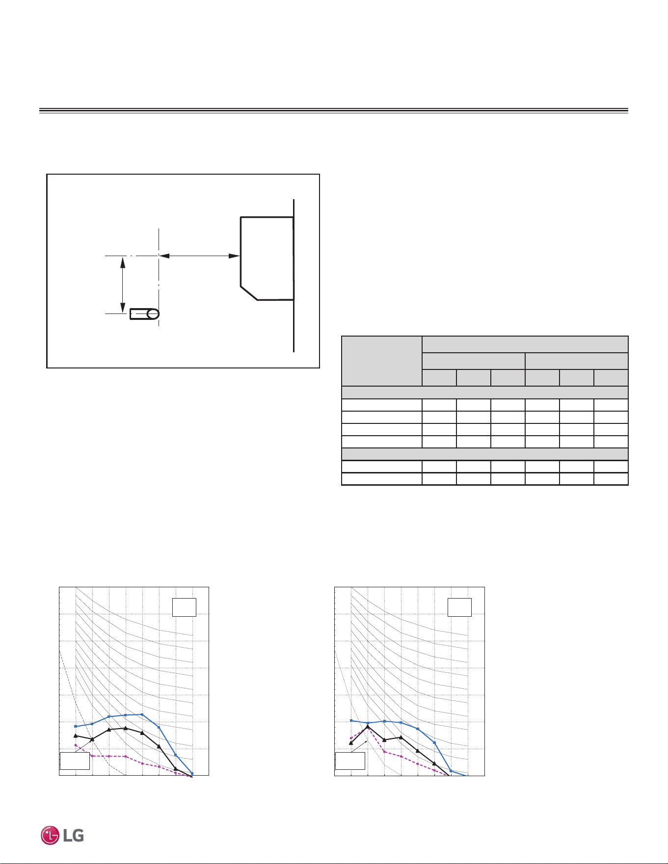
Figure 5: Sound Pressure Levels for Mega LSN090HEV2 Indoor Units.
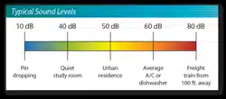
0HJDDQG0HJD9,QGRRU8QLWV
• Measurements are taken 3.3 ft away from the front of the unit.
• Sound pressure levels are measured in dB(A) with a tolerance of
±1.
• Data is valid at nominal operation conditions. Operating conditions
are assumed to be standard.
• 5HIHUHQFHDFRXVWLFSUHVVXUHG% ȝ3D
• Sound pressure levels are tested in an anechoic chamber under
ISO Standard 3745, and may be different according to the test
condition or equipment.
• Sound level will vary depending on a range of factors including the
construction (acoustic absorption coefficient) of a particular room in
which the unit was installed.
2.6 (0.8)
3.3 (1)
Microphone
Unit : ft. (m)
LSN090HEV2
Cooling Heating
10
20
30
40
50
60
70
80
63 125 250 500 1000 2000 4000 8000
Octave %DQG3UHVVXUH/HYHOG% ȝ3D
Ŷ High
Octave Band Center Frequency (Hz
Ɣ Low
ŸMiddle
NC-15
NC-20
NC-25
NC-30
NC-35
NC-40
NC-45
NC-50
NC-55
NC-60
NC-65
Approximate
Hearing
Threshold
10
20
30
40
50
60
70
80
63 125 250 500 1000 2000 4000 8000
Ŷ High
Octave Band Center Frequency (Hz
Ɣ Low
Ÿ Middle
Approximate
Hearing
Threshold
Octave %DQG3UHVVXUH/HYHOG% ȝ3D
NC-15
NC-20
NC-25
NC-30
NC-35
NC-40
NC-45
NC-50
NC-55
NC-60
NC-65
Indoor Unit Sound Pressure Measurement / Sound Pressure Levels
LSN090HEV2 Sound Pressure Levels
22 | PRODUCT DATA
Single Zone Mega Wall Mounted Engineering Manual
'XHWRRXUSROLF\RIFRQWLQXRXVSURGXFWLQQRYDWLRQVRPHVSHFL¿FDWLRQVPD\FKDQJHZLWKRXWQRWL¿FDWLRQ
©
/*(OHFWURQLFV86$,QF(QJOHZRRG&OLIIV1-$OOULJKWVUHVHUYHG³/*´LVDUHJLVWHUHGWUDGHPDUNRI/*&RUS
ACOUSTIC DATA
0HJDDQG0HJD9,QGRRU8QLWV
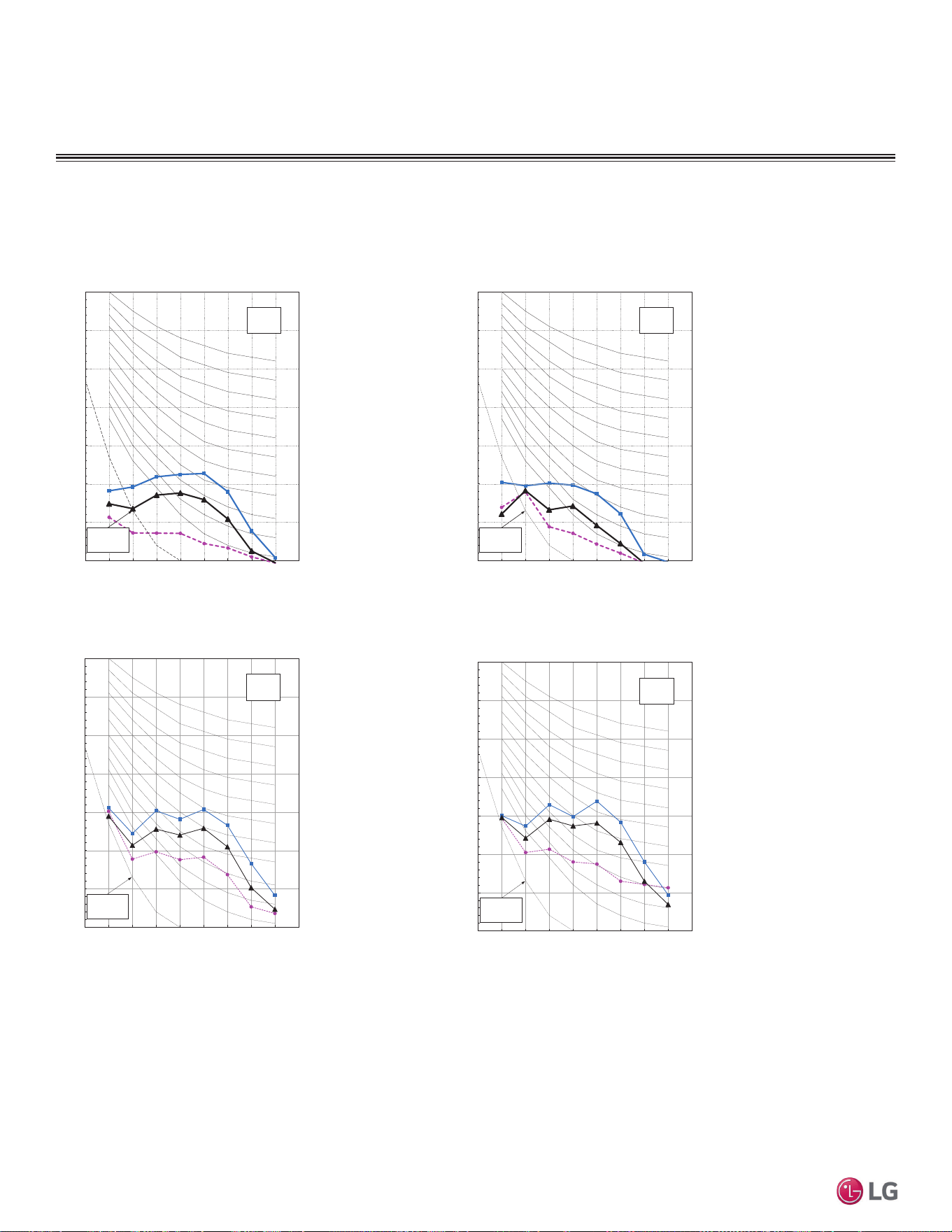
Figure 6: Sound Pressure Levels for Mega LSN120HEV2 Indoor Units.
Cooling Heating
10
20
30
40
50
60
70
80
63 125 250 500 1000 2000 4000 8000
Octave %DQG3UHVVXUH/HYHOG% ȝ3D
Ŷ High
Octave Band Center Frequency (Hz
Ɣ Low
ŸMiddle
NC-15
NC-20
NC-25
NC-30
NC-35
NC-40
NC-45
NC-50
NC-55
NC-60
NC-65
Approximate
Hearing
Threshold
10
20
30
40
50
60
70
80
63 125 250 500 1000 2000 4000 8000
Ŷ High
Octave Band Center Frequency (Hz
Ɣ Low
Ÿ Middle
Approximate
Hearing
Threshold
Octave %DQG3UHVVXUH/HYHOG% ȝ3D
NC-15
NC-20
NC-25
NC-30
NC-35
NC-40
NC-45
NC-50
NC-55
NC-60
NC-65
Cooling Heating
Octave Band Sound Pressure LevelG% ȝ3D
Octave Band Center Frequency (Hz
10
20
30
40
50
60
70
80
63 125 250 500 1000 2000 4000 8000
Ŷ High
Ɣ Low
Ÿ Middle
NC-15
NC-20
NC-25
NC-30
NC-35
NC-40
NC-45
NC-50
NC-55
NC-60
NC-65
Approximate
Hearing
Threshold
Octave Band Sound Pressure LevelG% ȝ3D
Octave Band Center Frequency (Hz
10
20
30
40
50
60
70
80
63 125 250 500 1000 2000 4000 8000
Ŷ High
Ɣ Low
Ÿ Middle
NC-15
NC-20
NC-25
NC-30
NC-35
NC-40
NC-45
NC-50
NC-55
NC-60
NC-65
Approximate
Hearing
Threshold
LSN120HEV2
LSN180HEV2
Figure 7: Sound Pressure Levels for Mega LSN180HEV2 Indoor Units.
LSN120HEV2 and LSN180HEV2 Sound Pressure Levels
PRODUCT DATA | 23
Product Data
'XHWRRXUSROLF\RIFRQWLQXRXVSURGXFWLQQRYDWLRQVRPHVSHFL¿FDWLRQVPD\FKDQJHZLWKRXWQRWL¿FDWLRQ
©
/*(OHFWURQLFV86$,QF(QJOHZRRG&OLIIV1-$OOULJKWVUHVHUYHG³/*´LVDUHJLVWHUHGWUDGHPDUNRI/*&RUS
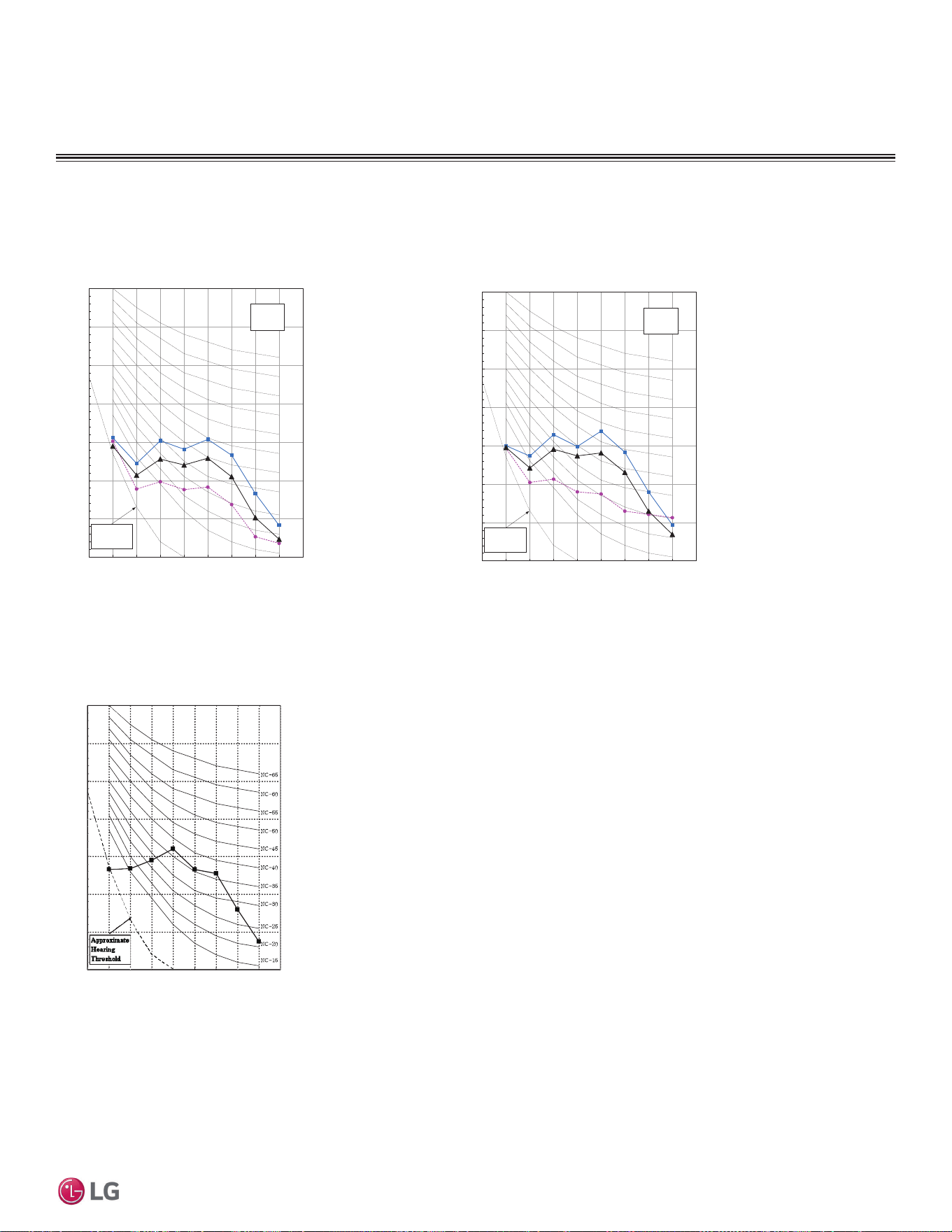
Figure 8: Sound Pressure Levels for Mega LSN180HEV2 Indoor Units.
Figure 9: Sound Pressure Levels for Mega 115V Indoor Units.
LSN240HEV2
Cooling Heating
Octave Band Sound Pressure LevelG% ȝ3D
Octave Band Center Frequency (Hz
10
20
30
40
50
60
70
80
63 125 250 500 1000 2000 4000 8000
Ŷ High
Ɣ Low
Ÿ Middle
NC-15
NC-20
NC-25
NC-30
NC-35
NC-40
NC-45
NC-50
NC-55
NC-60
NC-65
Approximate
Hearing
Threshold
Octave Band Sound Pressure LevelG% ȝ3D
Octave Band Center Frequency (Hz
10
20
30
40
50
60
70
80
63 125 250 500 1000 2000 4000 8000
Ŷ High
Ɣ Low
Ÿ Middle
NC-15
NC-20
NC-25
NC-30
NC-35
NC-40
NC-45
NC-50
NC-55
NC-60
NC-65
Approximate
Hearing
Threshold
ACOUSTIC DATA
0HJDDQG0HJD9,QGRRU8QLWV
2FWDYH%DQG6RXQG3UHVVXUH/HYHOG% ȝ3D
Octave Band Center Frequency +]
10
20
30
40
50
60
70
80
63 125 250 500 1000 2000 4000 8000
LSN090HXV, LSN120HXV
LSN240HEV2 Sound Pressure Levels
LSN090HXV and LSN120HXV Sound Pressure Levels
24 | PRODUCT DATA
Single Zone Mega Wall Mounted Engineering Manual
'XHWRRXUSROLF\RIFRQWLQXRXVSURGXFWLQQRYDWLRQVRPHVSHFL¿FDWLRQVPD\FKDQJHZLWKRXWQRWL¿FDWLRQ
©
/*(OHFWURQLFV86$,QF(QJOHZRRG&OLIIV1-$OOULJKWVUHVHUYHG³/*´LVDUHJLVWHUHGWUDGHPDUNRI/*&RUS
0HJDDQG0HJD92XWGRRU8QLWV
Model
Sound Pressure Levels (dB[A])
Cooling (High) Heating (High.)
Mega
LSU090HEV2 50 50
LSU120HEV2 50 50
LSU180HEV2 55 55
LSU240HEV2 55 55
Mega 115V
LSU090HXV 47 47
LSU120HXV 47 47
Table 9: Outdoor Unit Acoustic Data
Figure 10: Outdoor Unit Sound Levels
Figure 11: Sound Pressure Levels for Mega LSU090HEV2 Outdoor Units.
ACOUSTIC DATA
3.3 (1)
Center of
Outdoor Unit
Unit: ft. (mm)
Diagram above for illustrative purposes only. Actual appearance differs depending on
outdoor unit model.
• Measurements are taken 3.3 ft away from the front of the unit.
• Sound pressure levels are measured in dB(A) with a tolerance of
±1.
• Data is valid at nominal operation conditions. Operating conditions
are assumed to be standard.
• 5HIHUHQFHDFRXVWLFSUHVVXUHG% ȝ3D
• Sound pressure levels are tested in an anechoic chamber under
ISO Standard 3745, and may be different according to the test
condition or equipment.
• Sound level will vary depending on a range of factors including the
construction (acoustic absorption coefficient) of a particular room in
which the unit was installed.
LSU090HEV2
Cooling Heating
10
20
30
40
50
60
70
80
63 125 250 500 1000 2000 4000 8000
Ÿ
Ɣ
Front
Back
Octave Band Center Frequency (Hz)
NC-15
NC-20
NC-25
NC-30
NC-35
NC-40
NC-45
NC-50
NC-55
NC-60
NC-65
Approximate
Hearing
Threshold
Octave %DQG3UHVVXUH/HYHOG% ȝ3D
10
20
30
40
50
60
70
80
63 125 250 500 1000 2000 4000 8000
Octave %DQG3UHVVXUH/HYHOG% ȝ3D
Ɣ
ŸFront
Back
Octave Band Center Frequency (Hz)
Approximate
Hearing
Threshold
NC-15
NC-20
NC-25
NC-30
NC-35
NC-40
NC-45
NC-50
NC-55
NC-60
NC-65
Outdoor Unit Sound Pressure Measurement / Sound Pressure Levels
LSU090HEV2 Sound Pressure Levels
PRODUCT DATA | 25
Product Data
'XHWRRXUSROLF\RIFRQWLQXRXVSURGXFWLQQRYDWLRQVRPHVSHFL¿FDWLRQVPD\FKDQJHZLWKRXWQRWL¿FDWLRQ
©
/*(OHFWURQLFV86$,QF(QJOHZRRG&OLIIV1-$OOULJKWVUHVHUYHG³/*´LVDUHJLVWHUHGWUDGHPDUNRI/*&RUS
Figure 12: Sound Pressure Levels for Mega LSU120HEV2 Outdoor Units.
0HJDDQG0HJD92XWGRRU8QLWV
ACOUSTIC DATA
Figure 13: Sound Pressure Levels for Mega LSU180HEV2 Outdoor Units.
LSU120HEV2
LSU180HEV2
Cooling Heating
10
20
30
40
50
60
70
80
63 125 250 500 1000 2000 4000 8000
Ÿ
Ɣ
Front
Back
Octave Band Center Frequency (Hz)
NC-15
NC-20
NC-25
NC-30
NC-35
NC-40
NC-45
NC-50
NC-55
NC-60
NC-65
Approximate
Hearing
Threshold
Octave %DQG3UHVVXUH/HYHOG% ȝ3D
10
20
30
40
50
60
70
80
63 125 250 500 1000 2000 4000 8000
Octave %DQG3UHVVXUH/HYHOG% ȝ3D
Ɣ
ŸFront
Back
Octave Band Center Frequency (Hz)
Approximate
Hearing
Threshold
NC-15
NC-20
NC-25
NC-30
NC-35
NC-40
NC-45
NC-50
NC-55
NC-60
NC-65
Octave Band Sound Pressure LevelG% ȝ3D
Octave Band Center Frequency (Hz)
10
20
30
40
50
60
70
80
63 125 250 500 1000 2000 4000 8000
Ÿ
Ɣ
Front
Back
NC-15
NC-20
NC-25
NC-30
NC-35
NC-40
NC-45
NC-50
NC-55
NC-60
NC-65
Approximate
Hearing
Threshold
Octave Band Sound Pressure LevelG% ȝ3D
Octave Band Center Frequency (Hz)
10
20
30
40
50
60
70
80
63 125 250 500 1000 2000 4000 8000
Ÿ
Ɣ
Front
Back
NC-15
NC-20
NC-25
NC-30
NC-35
NC-40
NC-45
NC-50
NC-55
NC-60
NC-65
Approximate
Hearing
Threshold
Cooling Heating
LSU120HEV2 and LSU180HEV2 Sound Pressure Levels
26 | PRODUCT DATA
Single Zone Mega Wall Mounted Engineering Manual
'XHWRRXUSROLF\RIFRQWLQXRXVSURGXFWLQQRYDWLRQVRPHVSHFL¿FDWLRQVPD\FKDQJHZLWKRXWQRWL¿FDWLRQ
©
/*(OHFWURQLFV86$,QF(QJOHZRRG&OLIIV1-$OOULJKWVUHVHUYHG³/*´LVDUHJLVWHUHGWUDGHPDUNRI/*&RUS
0HJDDQG0HJD92XWGRRU8QLWV
ACOUSTIC DATA
Octave Band Center Frequency (Hz)
2FWDYH%DQG6RXQG3UHVVXUH/HYHOG% ȝ3D
10
20
30
40
50
60
70
80
63 125 250 500 1000 2000 4000 8000
NC-15
NC-20
NC-25
NC-30
NC-35
NC-40
NC-45
NC-50
NC-55
NC-60
NC-65
Approximate
Hearing
Threshold
LSU090HXV
10
20
30
40
50
60
70
80
63 125 250 500 1000 2000 4000 8000
NC-15
NC-20
NC-25
NC-30
NC-35
NC-40
NC-45
NC-50
NC-55
NC-60
NC-65
Approximate
Hearing
Threshold
2FWDYH%DQG6RXQG3UHVVXUH/HYHOG% ȝ3D
2FWDYH%DQG&HQWHU)UHTXHQF\+]
LSU120HXV
Figure 14: Sound Pressure Levels for Mega LSU240HEV2 Outdoor Units.
Figure 15: Sound Pressure Levels for Mega 115V Outdoor Units.
LSU240HEV2
Octave Band Sound Pressure LevelG% ȝ3D
Octave Band Center Frequency (Hz
10
20
30
40
50
60
70
80
63 125 250 500 1000 2000 4000 8000
Ÿ
Ɣ
Front
Back
NC-15
NC-20
NC-25
NC-30
NC-35
NC-40
NC-45
NC-50
NC-55
NC-60
NC-65
Approximate
Hearing
Threshold
Octave Band Sound Pressure LevelG% ȝ3D
Octave Band Center Frequency (Hz
10
20
30
40
50
60
70
80
63 125 250 500 1000 2000 4000 8000
Ÿ
Ɣ
Front
Back
NC-15
NC-20
NC-25
NC-30
NC-35
NC-40
NC-45
NC-50
NC-55
NC-60
NC-65
Approximate
Hearing
Threshold
Cooling Heating
LSU240HEV2 Sound Pressure Levels
LSU090HXV and LSU120HXV Sound Pressure Levels
PRODUCT DATA | 27
Product Data
'XHWRRXUSROLF\RIFRQWLQXRXVSURGXFWLQQRYDWLRQVRPHVSHFL¿FDWLRQVPD\FKDQJHZLWKRXWQRWL¿FDWLRQ
©
/*(OHFWURQLFV86$,QF(QJOHZRRG&OLIIV1-$OOULJKWVUHVHUYHG³/*´LVDUHJLVWHUHGWUDGHPDUNRI/*&RUS
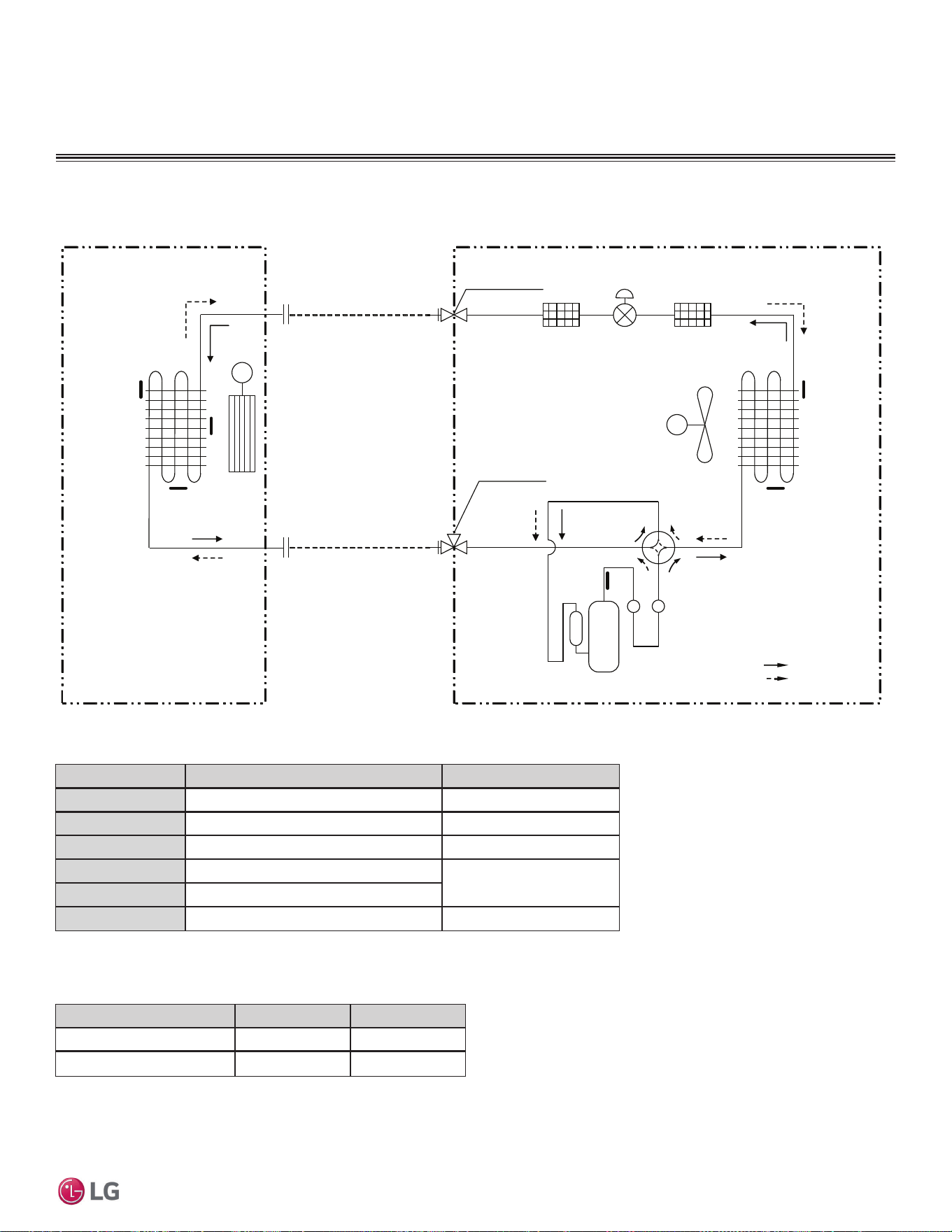
REFRIGERANT FLOW DIAGRAMS
Mega LSN / LSU090, 120, 180, 240HEV2
Refrigerant Flow Diagram for Mega LSN / LSU090, 120, 180, 240HEV2
Mufflers
Strainer
Field Pipin g
(Copper Tubing)
Field Pipin g
(Copper Tubing)
M
M
Heat
Exchanger
(Evaporator)
Heat
Exchanger
(Condenser)
Compressor
2-Way Valve
Reversing
Valve
(4-Way
Valve)
Indoor Unit Outdoor Unit
: Cooling
: Heating
EEV
TH1
TH2
TH4
TH5
TH6
Liquid Side
Vapor Side
3-Way Valve
TH3
Propeller
Fan
Cross
Flow
Fan
Flare
Joint
Flare
Joint
(Electronic
Expansion
Valve)
Strainer
Table 10: Mega LSN/LSU090-240HEV2 Thermistor Details.
Thermistor Description PCB Connector
TH1
Indoor air temperature thermistor CN-TH1 (Indoor)
TH2
Evaporator temperature thermistor CN-TH3 (Indoor)
TH3
Water Level Sensor (Option) CN-TH2 (Indoor)
TH4
Outdoor air temperature thermistor
CN-TH1 (Outdoor)
TH5
Condenser temperature thermistor
TH6
Discharge pipe temperature thermistor CN-TH2 (Outdoor)
Table 11: Mega LSN / LSU090-240HEV2 Refrigerant Piping Sizes.
Model No. Vapor (Inch [mm]) Liquid (Inch [mm])
LS090HEV2, LS120HEV2 Ø3/8 (Ø9.52) Ø1/4 (Ø6.35)
LS180HEV2, LS240HEV2 Ø1/2 (Ø12.7) Ø1/4 (Ø6.35)
28 | PRODUCT DATA
Single Zone Mega Wall Mounted Engineering Manual
'XHWRRXUSROLF\RIFRQWLQXRXVSURGXFWLQQRYDWLRQVRPHVSHFL¿FDWLRQVPD\FKDQJHZLWKRXWQRWL¿FDWLRQ
©
/*(OHFWURQLFV86$,QF(QJOHZRRG&OLIIV1-$OOULJKWVUHVHUYHG³/*´LVDUHJLVWHUHGWUDGHPDUNRI/*&RUS
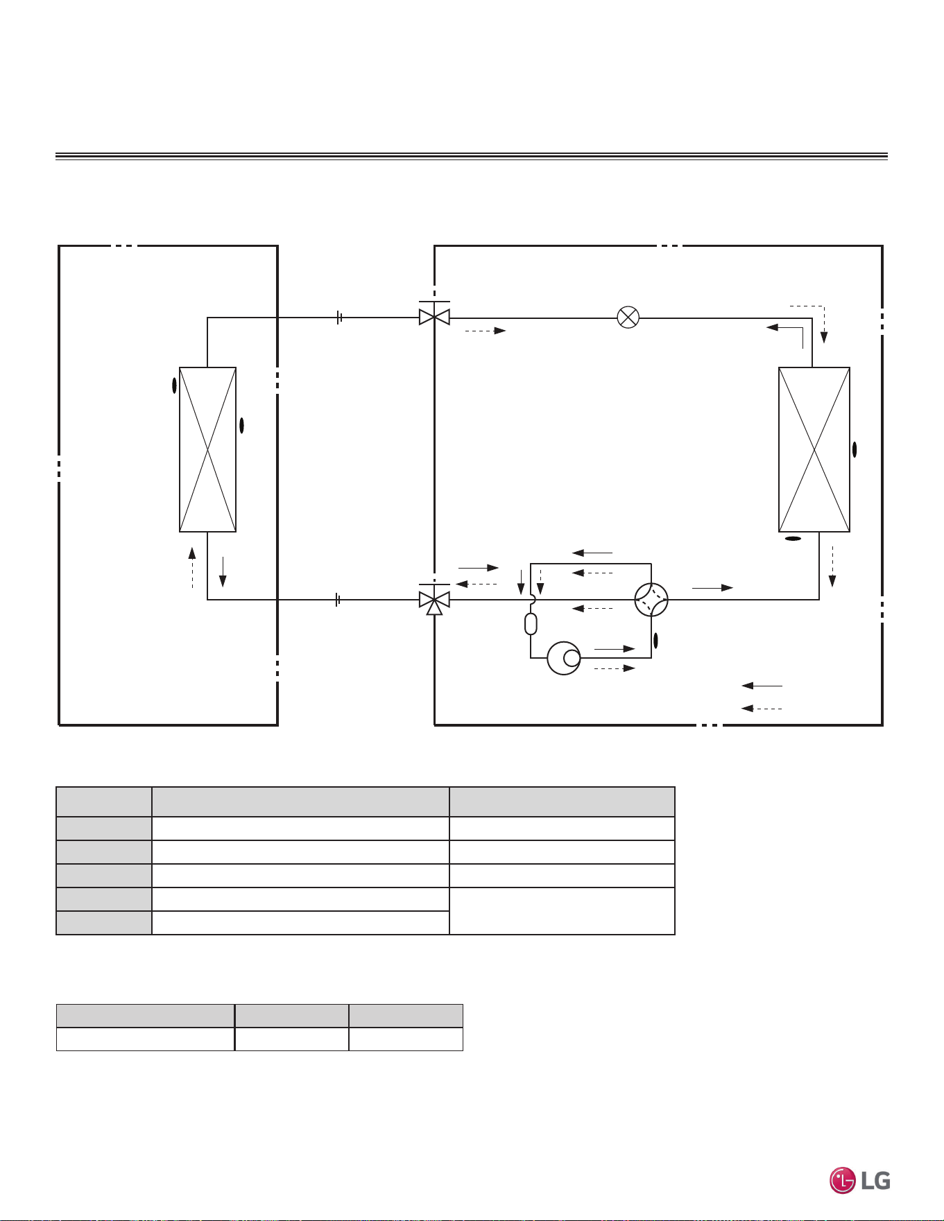
REFRIGERANT FLOW DIAGRAMS
Mega 115V LSN / LSU090, 120HXV
Thermistor Description PCB Connector
TH1
Indoor air temperature thermistor CN-TH1 (Indoor)
TH2
Evaporator middle temperature thermistor CN-TH2 (Indoor)
TH3
Discharge pipe temperature thermistor CN-TH2 (Outdoor)
TH4
Condensing middle temperature thermistor
CN-TH1 (Outdoor)
TH5
Outdoor air temperature thermistor
tinU roodtuOtinU roodnI
Heat
Exchanger
(Evaporator)
Heat
Exchanger
(Condenser)
Compressor
Accumulator
Vapor Side
3-Way Valve
2-Way Valve
Liquid Side
Cooling
Heating
Reversing Valve
EEV
FIELD PIPING
(Ø1/4" Copper Tubing)
FIELD PIPING
(Ø3/8" Copper Tubing)
TH1
TH4
TH5
TH2
TH3
Refrigerant Flow Diagram for Mega 115 LSN / LSU090, 120HXV
Table 12: Mega 115 LSN/LSU090-120HXV Thermistor Details.
Table 13: Mega 115 LSN / LSU090-120HXV Refrigerant Piping Sizes.
Model No. Vapor (Inch [mm]) Liquid (Inch [mm])
LS090HXV, LS120HXV Ø3/8 (Ø9.52) Ø1/4 (Ø6.35)
PRODUCT DATA | 29
Product Data
'XHWRRXUSROLF\RIFRQWLQXRXVSURGXFWLQQRYDWLRQVRPHVSHFL¿FDWLRQVPD\FKDQJHZLWKRXWQRWL¿FDWLRQ
©
/*(OHFWURQLFV86$,QF(QJOHZRRG&OLIIV1-$OOULJKWVUHVHUYHG³/*´LVDUHJLVWHUHGWUDGHPDUNRI/*&RUS
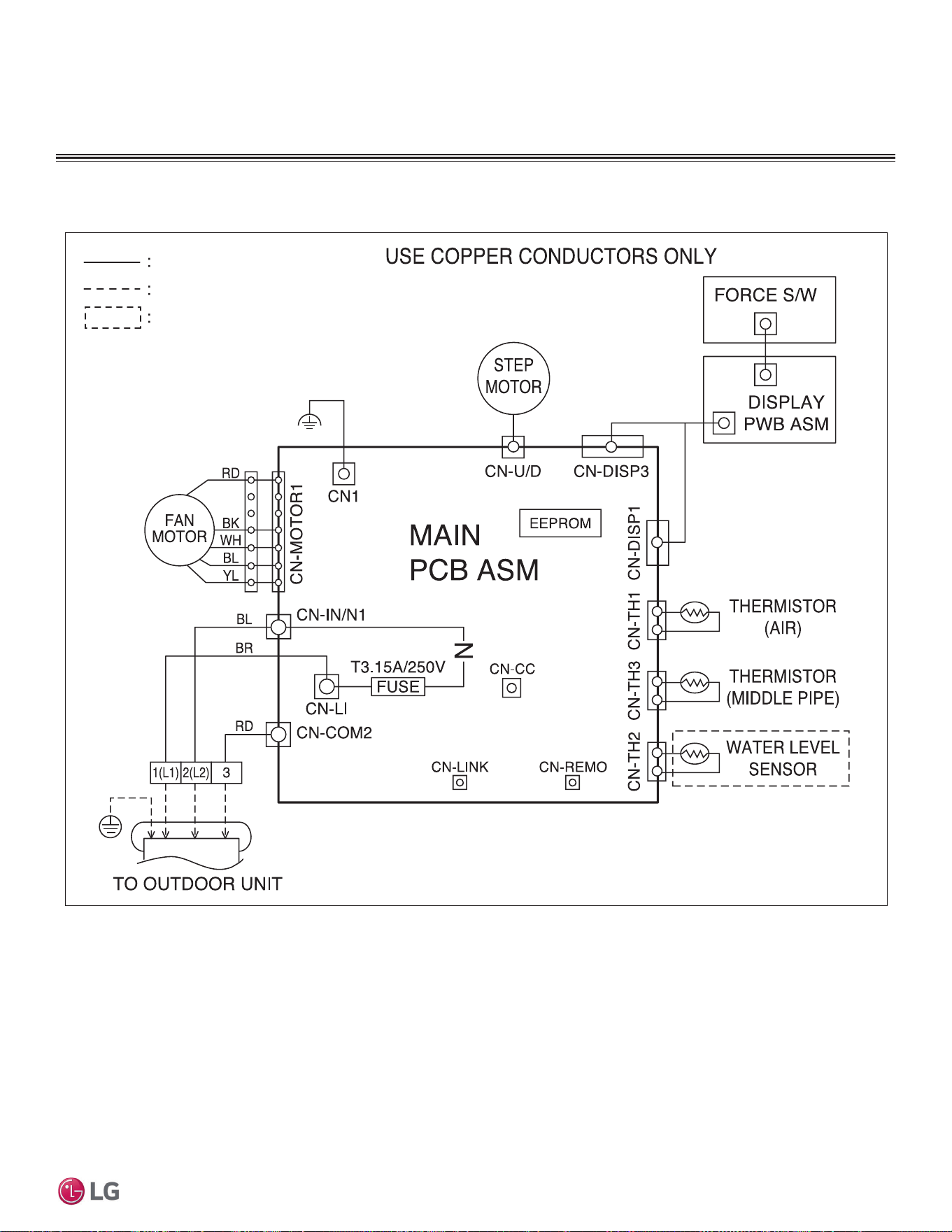
INDOOR UNIT WIRING DIAGRAM
Mega LSN090, 120, 180, 240HEV2
Wiring Diagram for LSN090, 120, 180, 240HEV2
Option
Field Wiring
Factory Wiring
MEZ64135636
30 | PRODUCT DATA
Single Zone Mega Wall Mounted Engineering Manual
'XHWRRXUSROLF\RIFRQWLQXRXVSURGXFWLQQRYDWLRQVRPHVSHFL¿FDWLRQVPD\FKDQJHZLWKRXWQRWL¿FDWLRQ
©
/*(OHFWURQLFV86$,QF(QJOHZRRG&OLIIV1-$OOULJKWVUHVHUYHG³/*´LVDUHJLVWHUHGWUDGHPDUNRI/*&RUS
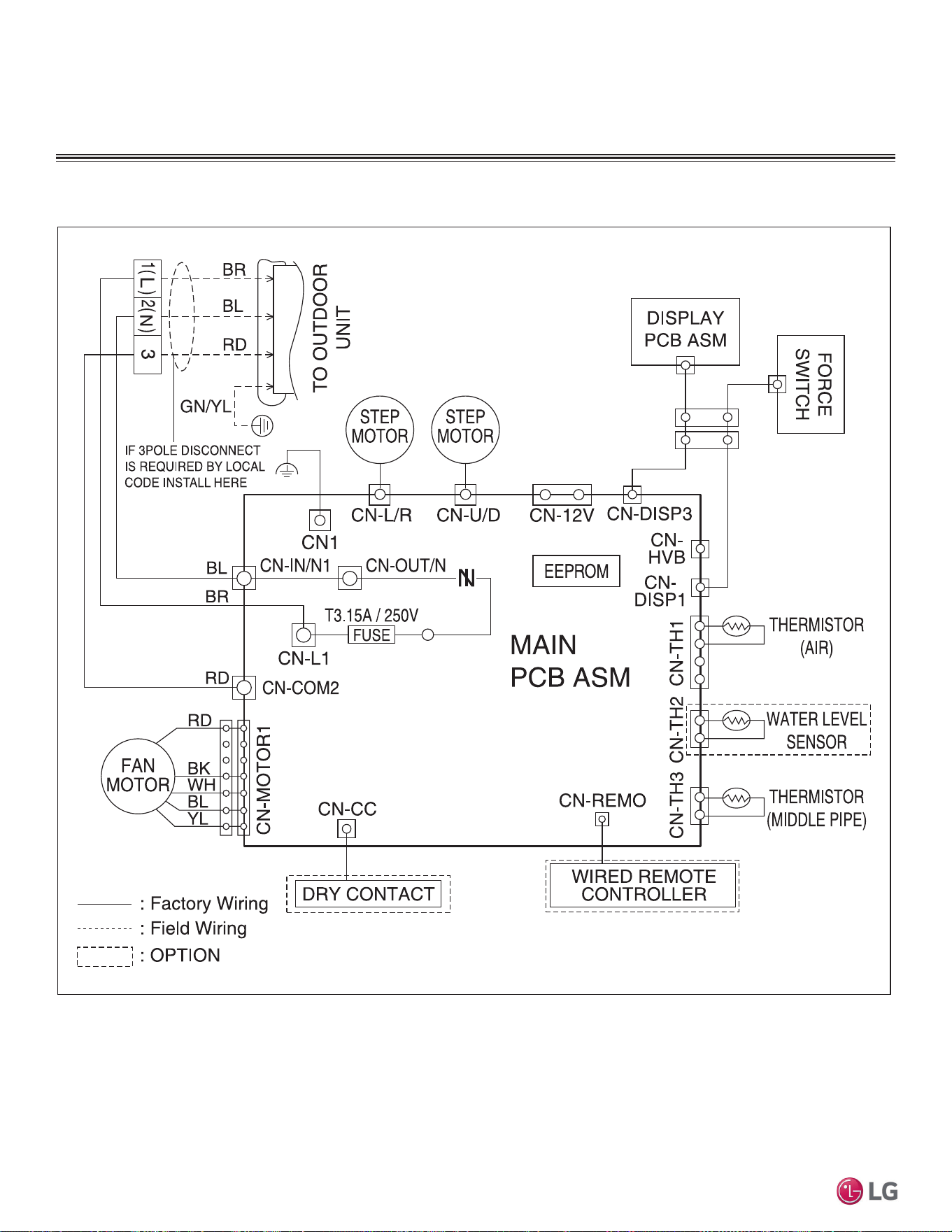
Wiring Diagram for LSN090, 120HXV
INDOOR UNIT WIRING DIAGRAM
Mega 115V LSN090HXV and LSN120HXV
PRODUCT DATA | 31
Product Data
'XHWRRXUSROLF\RIFRQWLQXRXVSURGXFWLQQRYDWLRQVRPHVSHFL¿FDWLRQVPD\FKDQJHZLWKRXWQRWL¿FDWLRQ
©
/*(OHFWURQLFV86$,QF(QJOHZRRG&OLIIV1-$OOULJKWVUHVHUYHG³/*´LVDUHJLVWHUHGWUDGHPDUNRI/*&RUS
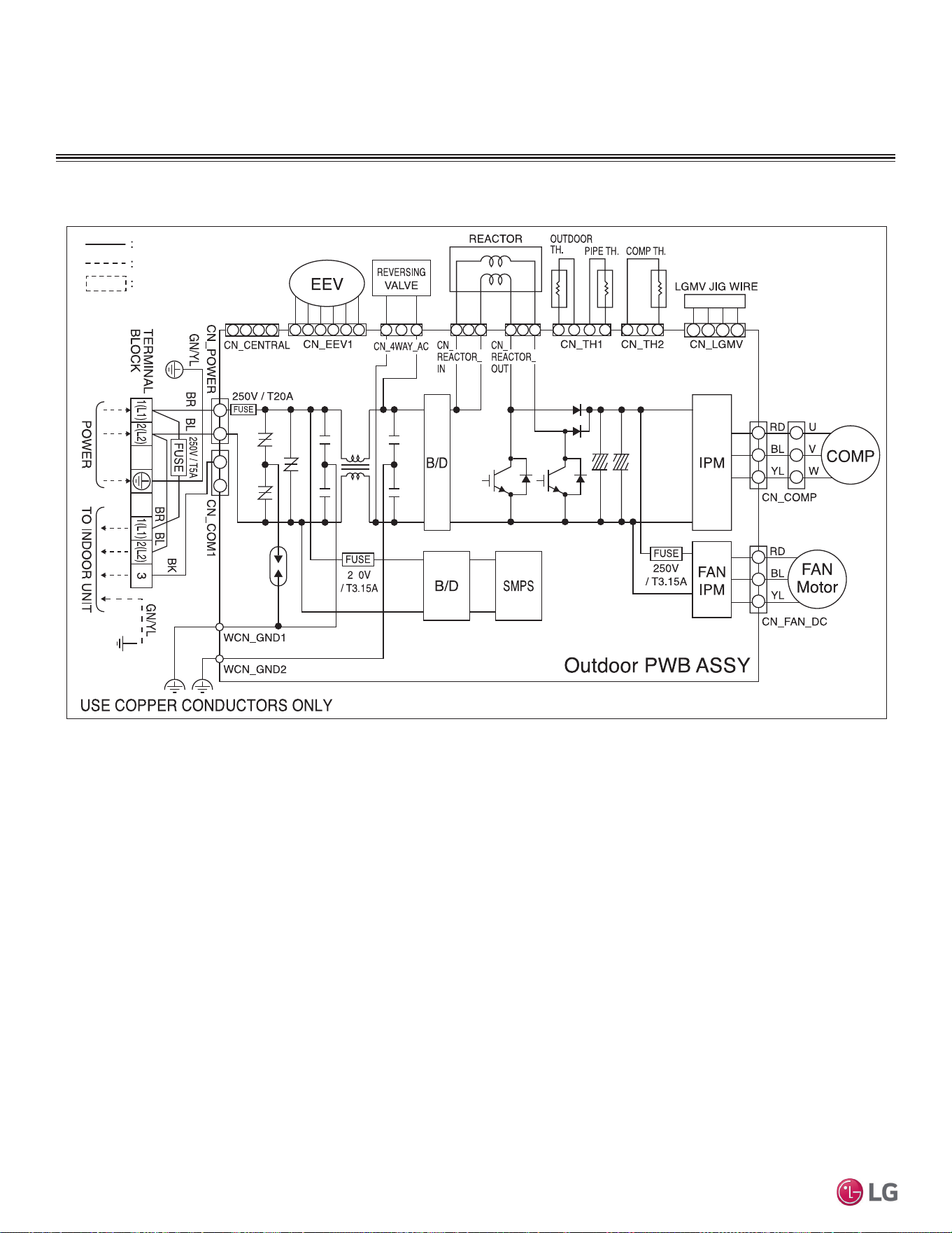
OUTDOOR UNIT WIRING DIAGRAM
Mega LSU090, 120HEV2
Wiring Diagram for LSU090, 120HEV2
Option
Field Wiring
Factory Wiring
MEZ64835136
32 | PRODUCT DATA
Single Zone Mega Wall Mounted Engineering Manual
'XHWRRXUSROLF\RIFRQWLQXRXVSURGXFWLQQRYDWLRQVRPHVSHFL¿FDWLRQVPD\FKDQJHZLWKRXWQRWL¿FDWLRQ
©
/*(OHFWURQLFV86$,QF(QJOHZRRG&OLIIV1-$OOULJKWVUHVHUYHG³/*´LVDUHJLVWHUHGWUDGHPDUNRI/*&RUS
OUTDOOR UNIT WIRING DIAGRAM
Mega LSU180, 240HEV2
Wiring Diagram for LSU180, 240HEV2
Option
Field Wiring
Factory Wiring
MEZ66177431
PRODUCT DATA | 33
Product Data
'XHWRRXUSROLF\RIFRQWLQXRXVSURGXFWLQQRYDWLRQVRPHVSHFL¿FDWLRQVPD\FKDQJHZLWKRXWQRWL¿FDWLRQ
©
/*(OHFWURQLFV86$,QF(QJOHZRRG&OLIIV1-$OOULJKWVUHVHUYHG³/*´LVDUHJLVWHUHGWUDGHPDUNRI/*&RUS
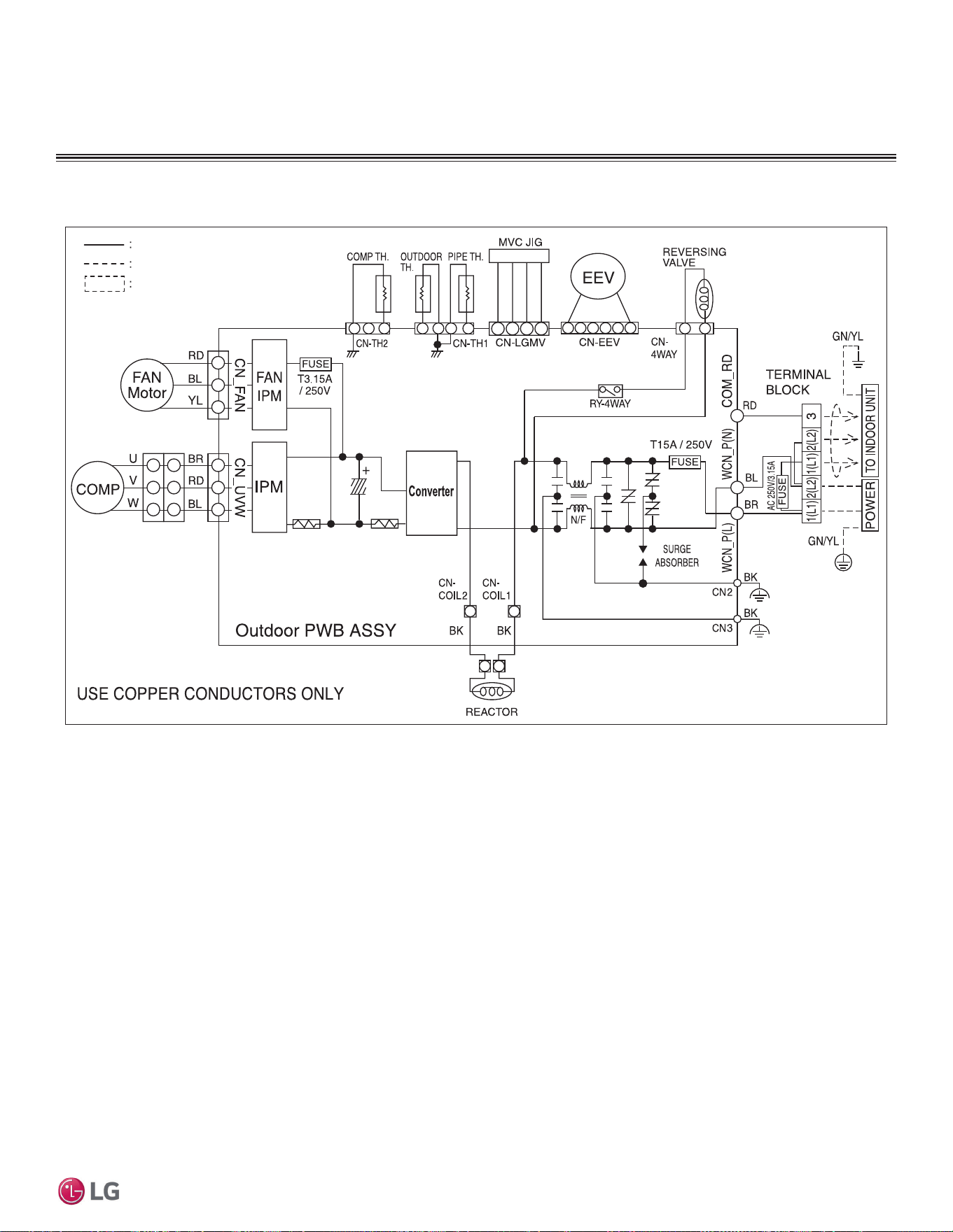
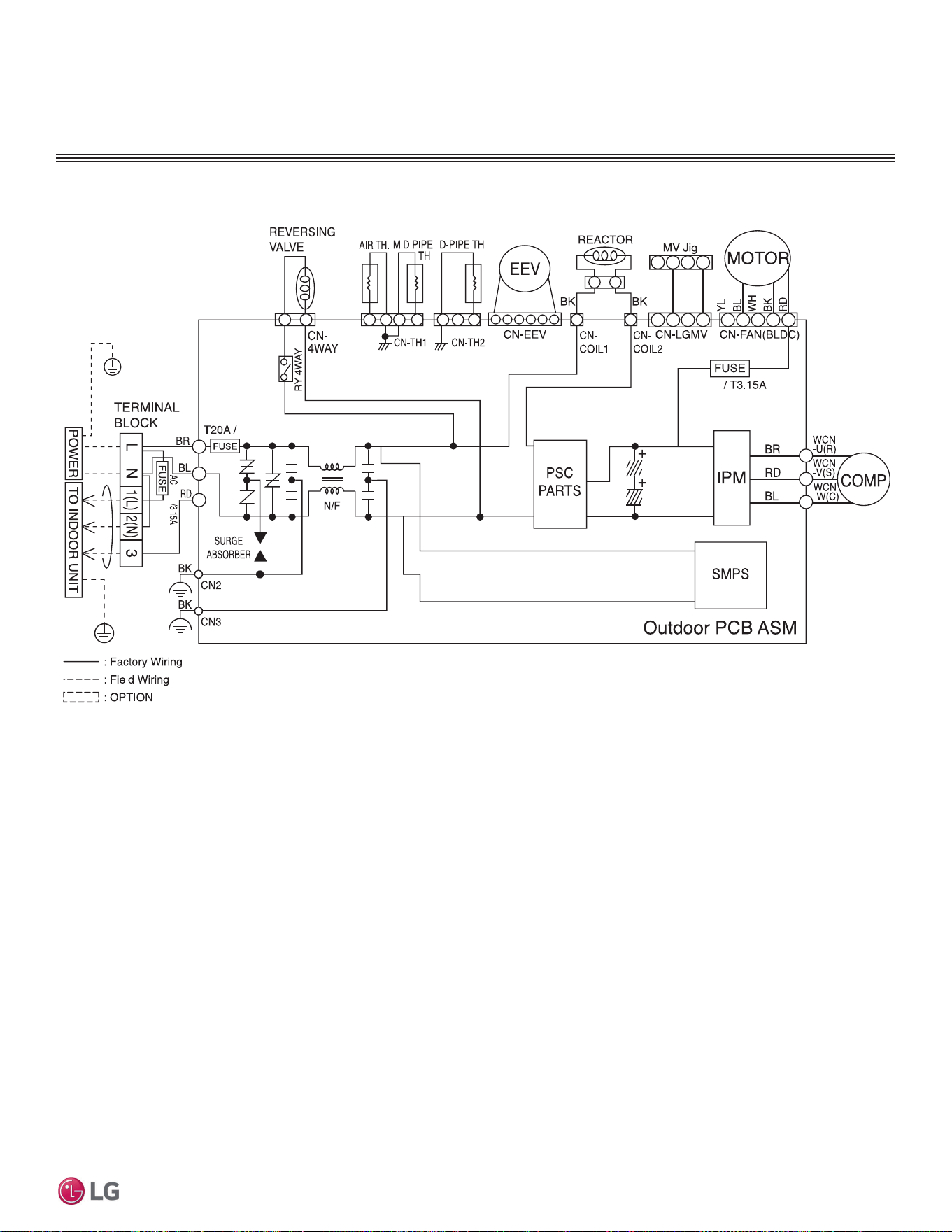
OUTDOOR UNIT WIRING DIAGRAM
Mega 115V LSU090, 120HXV
250V
250V
250V
Wiring Diagram for LSU090, 120HXV

34 | PRODUCT DATA
Single Zone Mega Wall Mounted Engineering Manual
'XHWRRXUSROLF\RIFRQWLQXRXVSURGXFWLQQRYDWLRQVRPHVSHFL¿FDWLRQVPD\FKDQJHZLWKRXWQRWL¿FDWLRQ
©
/*(OHFWURQLFV86$,QF(QJOHZRRG&OLIIV1-$OOULJKWVUHVHUYHG³/*´LVDUHJLVWHUHGWUDGHPDUNRI/*&RUS
ELECTRICAL CONNECTIONS
General Power Wiring / Communications Cable Guidelines
• Follow manufacturer’s circuit diagrams displayed on the inside of the control box cover.
• Have a separate power supply for the indoor units.
• Provide a circuit breaker switch between the power source and the indoor unit.
• Confirm power source specifications.
• Properly ground the outdoor unit and the indoor unit per National Electrical Code (NEC) and local codes.
• Connect the wiring firmly so that the wires cannot be easily pulled out.
• Confirm that the electrical capacity is sufficient.
• Power supply to the outdoor unit must be selected based on NEC and local codes. Maximum allowable voltage fluctuation ±10% or name-
plate rated value.
• It is recommended that a circuit breaker is installed, especially if conditions could become wet or moist.
• Include a disconnect in the power wiring system. Add an air gap contact separation of at least 1/8 inch in each active (phase) conductor.
• Any openings where the field wiring enters the cabinet must be completely sealed.
Do not install power wiring to the outdoor unit and the communication / connection (power) cable to the indoor unit in the same conduit.
Use separate conduits.
Power Wiring / Communications Cable Specifications
• Power wiring to the outdoor unit must be solid or stranded, and must comply with the applicable local and national electric codes.
• Communication / connection (power) cable from the outdoor unit to the indoor unit must be a minimum of 18 AWG, four (4) conductor,
stranded, shielded or unshielded (if shielded, must be grounded to chassis at the outdoor unit only) and must comply with applicable local
and national codes.
• Communication cable from the indoor unit to optional remote controller is to be 22 AWG, three (3) conductor, twisted, stranded, unshielded.
Wiring must comply with all applicable local and national codes.
• Terminal screws will become loose during transport. Properly tighten the terminal connections during installation or risk electric shock,
physical injury, or death.
• Loose wiring will cause unit to malfunction, overheat, and catch fire, resulting in severe injury or death.
• Terminal screws will loosen during transport. Properly tighten the terminal connections during installation or risk equipment malfunction or
property damage.
• Loose wiring will cause unit malfunction, the wires to burnout or the terminal to overheat and catch fire. There is a risk of equipment mal-
function or property damage.
A voltage drop will cause the following problems:
• Magnetic switch vibration, fuse breaks, or disturbance to the normal function of an overload protection device.
• Compressor will not receive the proper starting current.
PRODUCT DATA | 35
Product Data
'XHWRRXUSROLF\RIFRQWLQXRXVSURGXFWLQQRYDWLRQVRPHVSHFL¿FDWLRQVPD\FKDQJHZLWKRXWQRWL¿FDWLRQ
©
/*(OHFWURQLFV86$,QF(QJOHZRRG&OLIIV1-$OOULJKWVUHVHUYHG³/*´LVDUHJLVWHUHGWUDGHPDUNRI/*&RUS
ELECTRICAL CONNECTIONS
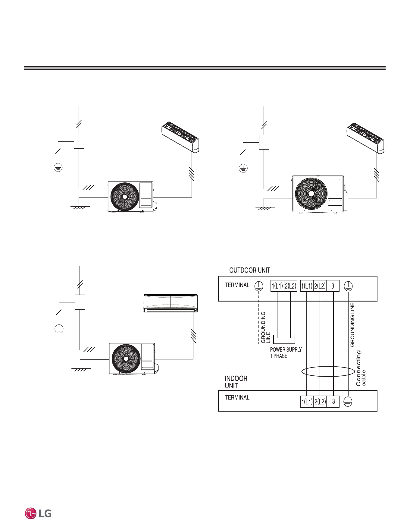
Figure 16: LS090HEV2 and LS120HEV2 General Power / Communica-
tions System Schematic.
Figure 17: LS180HEV2 and LS240HEV2 General Power / Communica-
tions System Schematic.
Figure 18: LS090HXV and LS120HXV General Power / Communica-
tions System Schematic.
LS090, 120HEV2
208/230 VAC
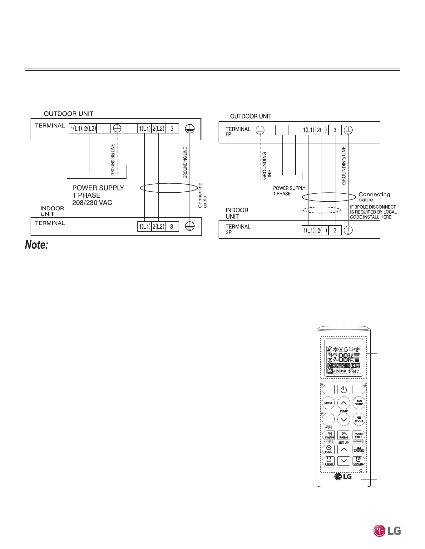
Figure 19: Terminal Block Wiring Diagram LS090-120HEV2.
Power Supply
Circuit Breaker
Ground Wiring
Outdoor Unit
Indoor Unit
Power Supply
Circuit Breaker
Ground Wiring
Outdoor Unit
Indoor Unit
Power Supply
Circuit Breaker
Ground Wiring
Outdoor Unit
Indoor Unit
36 | PRODUCT DATA
Single Zone Mega Wall Mounted Engineering Manual
'XHWRRXUSROLF\RIFRQWLQXRXVSURGXFWLQQRYDWLRQVRPHVSHFL¿FDWLRQVPD\FKDQJHZLWKRXWQRWL¿FDWLRQ
©
/*(OHFWURQLFV86$,QF(QJOHZRRG&OLIIV1-$OOULJKWVUHVHUYHG³/*´LVDUHJLVWHUHGWUDGHPDUNRI/*&RUS
ELECTRICAL CONNECTIONS
Controller Options
Single Zone Mega and Mega 115V Wall Mount systems include a wireless handheld remote controller
(Model Nos. AKB74955602 [Mega] and AKB73456121 [Mega 115V]). Optional LG-suppled wired control-
lers are available for the Mega 115V units. See “Functions, Controls, Options”, or contact an LG repre-
sentative for more information.
Wireless Handheld Remote Controller features:
• Display Panel: Displays operation conditions.
• On / Off Button: Turns system operation on and off.
• Mode Button: Selects the operation mode: Cooling, Heating, Auto, Dry
(Dehumidification), or Fan.
• Temp Up / Down Buttons: Adjusts the desired room temperature in the different modes.
• Fan Speed Button: Sets desired fan speed.
• Reset: Initializes the handheld remote control settings.
Wired Controller Connections
Optional controllers (see “Functions, Controls, Options”, or contact an LG representative for more infor-
mation) can connect to the Single Zone Mega 115V Wall Mount indoor unit in one of two different ways.
1. LG Wired Remote Extension Cable with Molex plug (PZCWRC1; sold separately) that connects to the
CN-REMO terminal on the indoor unit PCB.
2. Field-supplied controller cable that connects to the indoor unit terminal block (must be at least
UL2547 or UL1007, and at least FT-6 rated if local electric and building codes require plenum cable
usage). Communication cable from indoor unit to remote controller(s) is to be 22 AWG, 3-conductor,
twisted, stranded, unshielded. Wiring must comply with all applicable local and national codes.
Figure 20: Terminal Block Wiring Diagram LS180HEV2, LS240HEV2.
Display
Screen
Button
*
*
*
RESET
• Use a conduit for the communications cable / power wiring from the outdoor unit to the indoor units.
• Make sure the communications cable / power wiring from the outdoor units to the indoor units, and the power wiring to the outdoor unit are
separate, otherwise, the outdoor unit operation will be affected by electrical noise and will malfunction or fail.
LSU090HXV, LSU120HXV
N
N
N
L
115 VAC
LS180HEV2, LS240HEV2
Figure 21: Terminal Block Wiring Diagram LS090HXV, LS120HXV
Figure 22: AKB74955602 Wire-
less Handheld Remote Controller.
Buttons on the AKB73456121 will
differ.
PRODUCT DATA | 37
Product Data
'XHWRRXUSROLF\RIFRQWLQXRXVSURGXFWLQQRYDWLRQVRPHVSHFL¿FDWLRQVPD\FKDQJHZLWKRXWQRWL¿FDWLRQ
©
/*(OHFWURQLFV86$,QF(QJOHZRRG&OLIIV1-$OOULJKWVUHVHUYHG³/*´LVDUHJLVWHUHGWUDGHPDUNRI/*&RUS
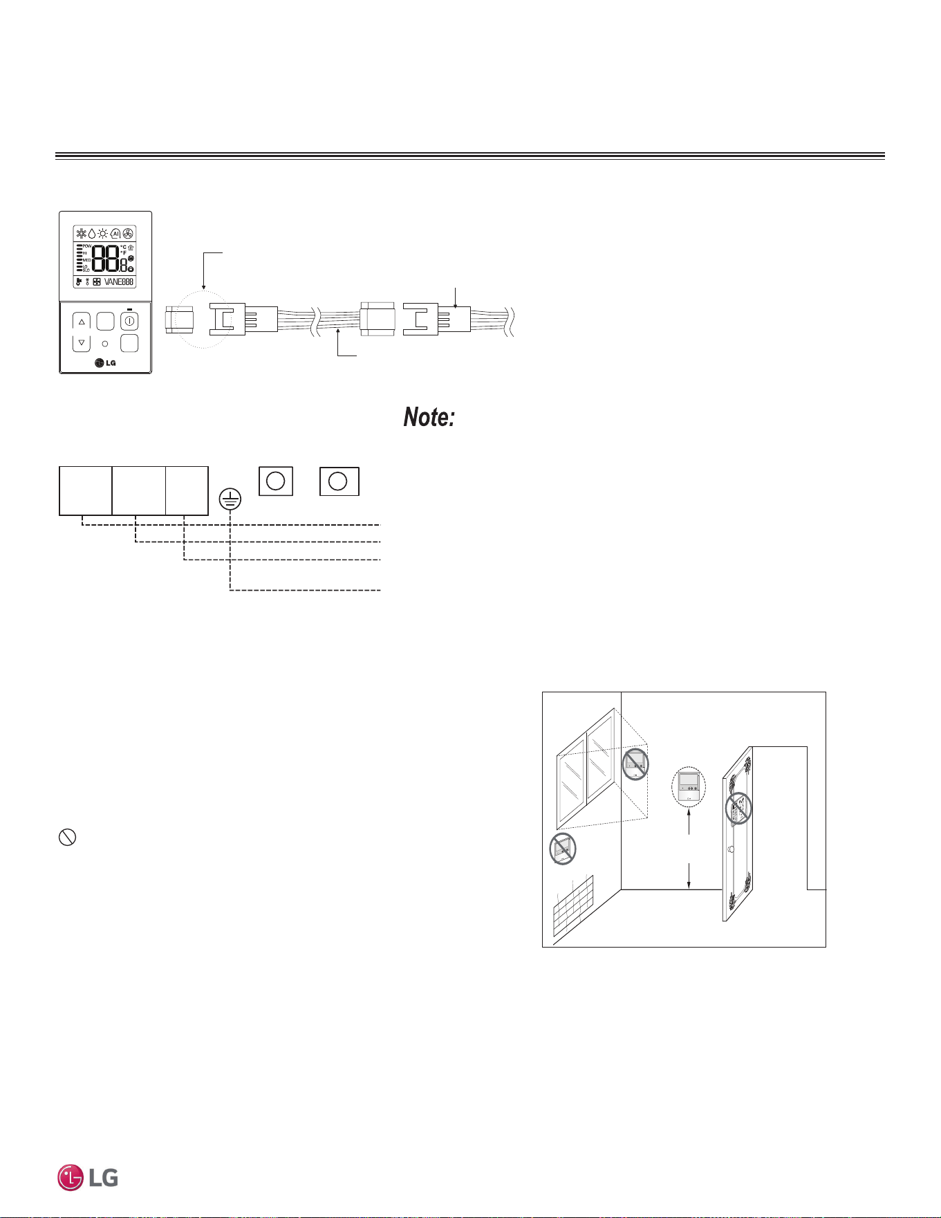
ELECTRICAL CONNECTIONS
Figure 23: Proper Location for the Wired Controller.
4 to 5 feet
above the floor
NO
NO
NO
YES
Remote Controlle r
TEMP
Remote Controlle r
TEMP
Re
m
ot
e
Co
nt
r
o
l
l
e
r
TEMP
Wired Controller Placement
Wired controllers include a sensor to detect room temperature. To
maintain comfort levels in the conditioned space, the wired control-
ler must be installed in a location away from direct sunlight, high
humidity, and where it could be directly exposed to cold air. Control-
ler must be installed four (4) to five (5) feet above the floor where its
LED display can be read easily, in an area with good air circulation,
and where it can detect an average room temperature.
Do not install the wired controller near or in:
• Drafts or dead spots behind doors and in corners.
• Hot or cold air from ducts.
• Radiant heat from the sun or appliances.
• Concealed pipes and chimneys.
• An area where temperatures are uncontrolled, such as an outside
wall.
Assigning the Thermistor for Temperature Detection
Each indoor unit includes a return air thermistor assigned to sense the temperature. If a wired controller is installed, there is a choice of
sensing temperature with either the indoor unit return air thermistor or the thermistor in the wired controller. It is also an option to set both
thermistors to sense temperature so that indoor unit bases its operation on the first thermistor to reach the designated temperature differen-
tial.
Figure 24: PZCWRC1 LG Wired Remote Extension Cable for Use with the Mega 115V.
Verify the connectors are properly inserted.
C/BOX Cable (Plug type)
Extension cable
To Indoor Unit
CN-REMO
Terminal
TEMP
FAN
SPEED
OPER
MODE
Figure 25: Wired Controller Connection on the Mega 115V
Indoor Unit Terminal Block.
:KHQXVLQJ¿HOGVXSSOLHGFRQWUROOHUFDEOHPDNHVXUHWRFRQQHFWWKH\HOORZWR\HOORZ
(communications wire), red to red (12V power wire), and black to black (ground wire)
terminals from the remote controller to the indoor unit terminal blocks.
Indoor Unit Terminal Block
1(L1 ) 2
GND
3
GRN /
YLW
BR
BL
RD
CN-REMOCN-CC
38 | PRODUCT DATA
Single Zone Mega Wall Mounted Engineering Manual
'XHWRRXUSROLF\RIFRQWLQXRXVSURGXFWLQQRYDWLRQVRPHVSHFL¿FDWLRQVPD\FKDQJHZLWKRXWQRWL¿FDWLRQ
©
/*(OHFWURQLFV86$,QF(QJOHZRRG&OLIIV1-$OOULJKWVUHVHUYHG³/*´LVDUHJLVWHUHGWUDGHPDUNRI/*&RUS
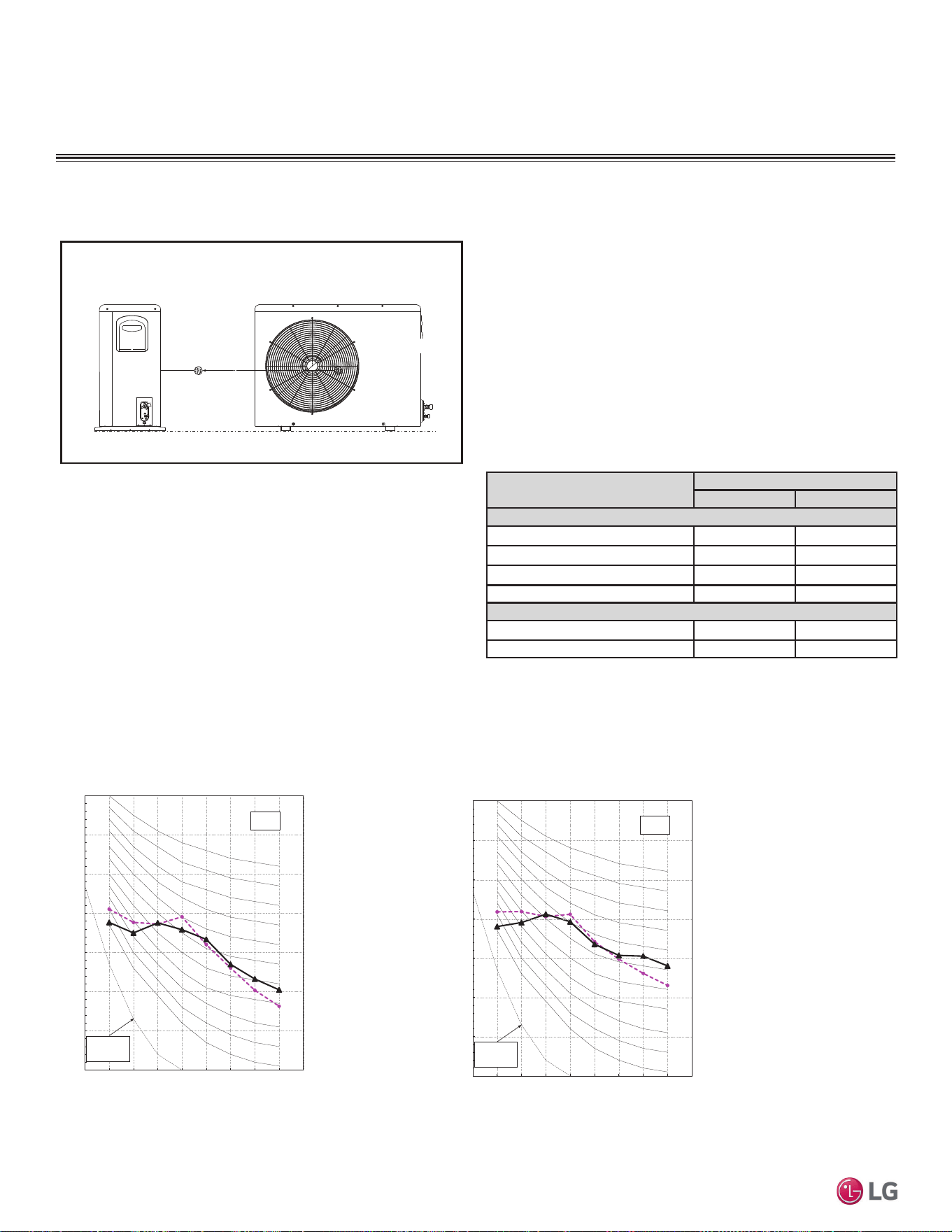
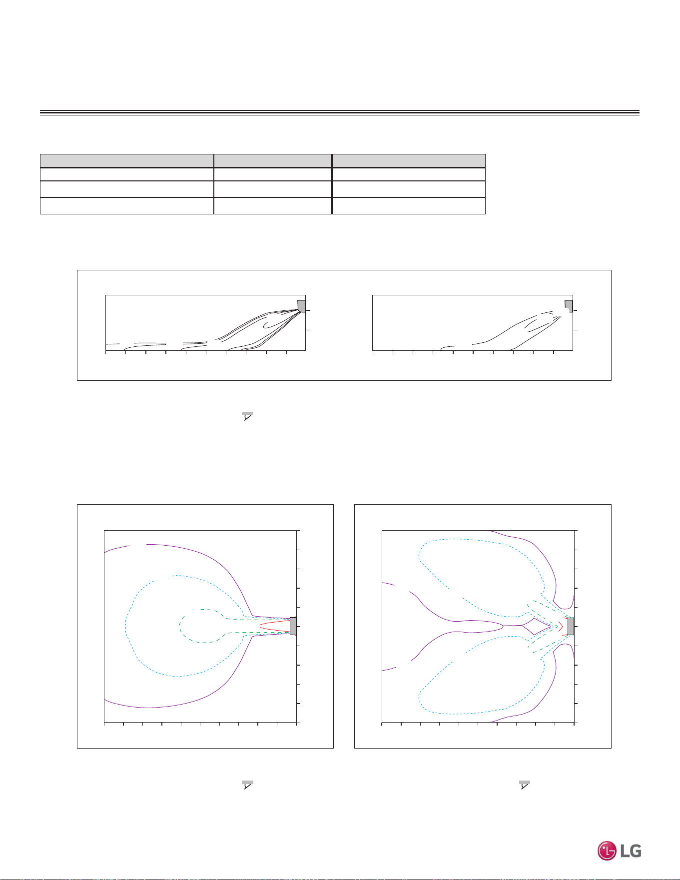
AIR FLOW, STATIC PRESSURE, AND TEMPERATURE
DISTRIBUTION
LSN090HEV2
Table 14: Mega and Mega 115V Outdoor Unit Air Flow Rate and Static Pressure.
Model No. Air Flow Rate (CFM) Static Pressure (in. WG)
LSU090HEV2, LSU120HEV2 953 0.0284
LSU180HEV2, LSU240HEV2 1,730 0.0387
LSU090HXV, LSU120HXV 953 0.0384
Cooling
0.5(1.6)
0.3(1)
1(3.3)
2(6.6)
Air Velocity [m/s (ft./s)]
1
0
0
10
2
2468
m
m
06.6
ft.
32.8 13.119.726.2
1
0
0
10
2
2468
m
3.3
0
mft.
6.6
ft.
3.3
0
6.6
0
ft.
32.8 6.613.119.726.2
28(82)
26(79)
24(75)
22(72)
0.3(1)
0.5(1.6)
1(3.3)
1(3.3)
1(3.3)
2(6.6)
0.3(1)
0.3(1)
0.5(1.6)
0.5(1.6)
2(6.6)
2(6.6)
Air Velocity [m/s (ft./s)]
0
m
10 2468
m
1
0
1
2
3
4
3
2
4
5
5
0
Air Velocity [m/s (ft./s)]
10 2468
m
1
0
1
2
3
4
3
2
4
5
5
0
ft.
32.8 6.613.119.726.2 032.8 6.613.119.726.2
m
ft.
ft.
3.3
0
3.3
6.6
9.8
13.1
9.8
6.6
13.1
16.4
16.4
3.3
3.3
6.6
9.8
13.1
9.8
6.6
13.1
16.4
16.4
ft.
0
Side View
Discharge $QJOHÛ)URPWKHIORRU )
Vertical Louver : Center
)DQ6SHHG3RZHU
TRSView
Discharge $QJOHÛ)URPWKHIORRU )
Vertical Louver : Center
)DQ6SHHG3RZHU
$LU6SHHGPVIWV5DQJH11.5 m (37.7 ft.)
TRSView
Discharge $QJOHÛ)URPWKHIORRU )
VHUWLFDO/RXYHU/HIW5LJKW
)DQ6SHHG3RZHU
THPSHUDWXUH>Û&Û)@
PRODUCT DATA | 39
Product Data
'XHWRRXUSROLF\RIFRQWLQXRXVSURGXFWLQQRYDWLRQVRPHVSHFL¿FDWLRQVPD\FKDQJHZLWKRXWQRWL¿FDWLRQ
©
/*(OHFWURQLFV86$,QF(QJOHZRRG&OLIIV1-$OOULJKWVUHVHUYHG³/*´LVDUHJLVWHUHGWUDGHPDUNRI/*&RUS
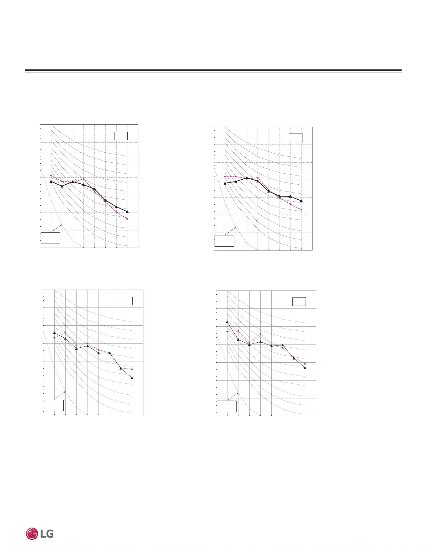
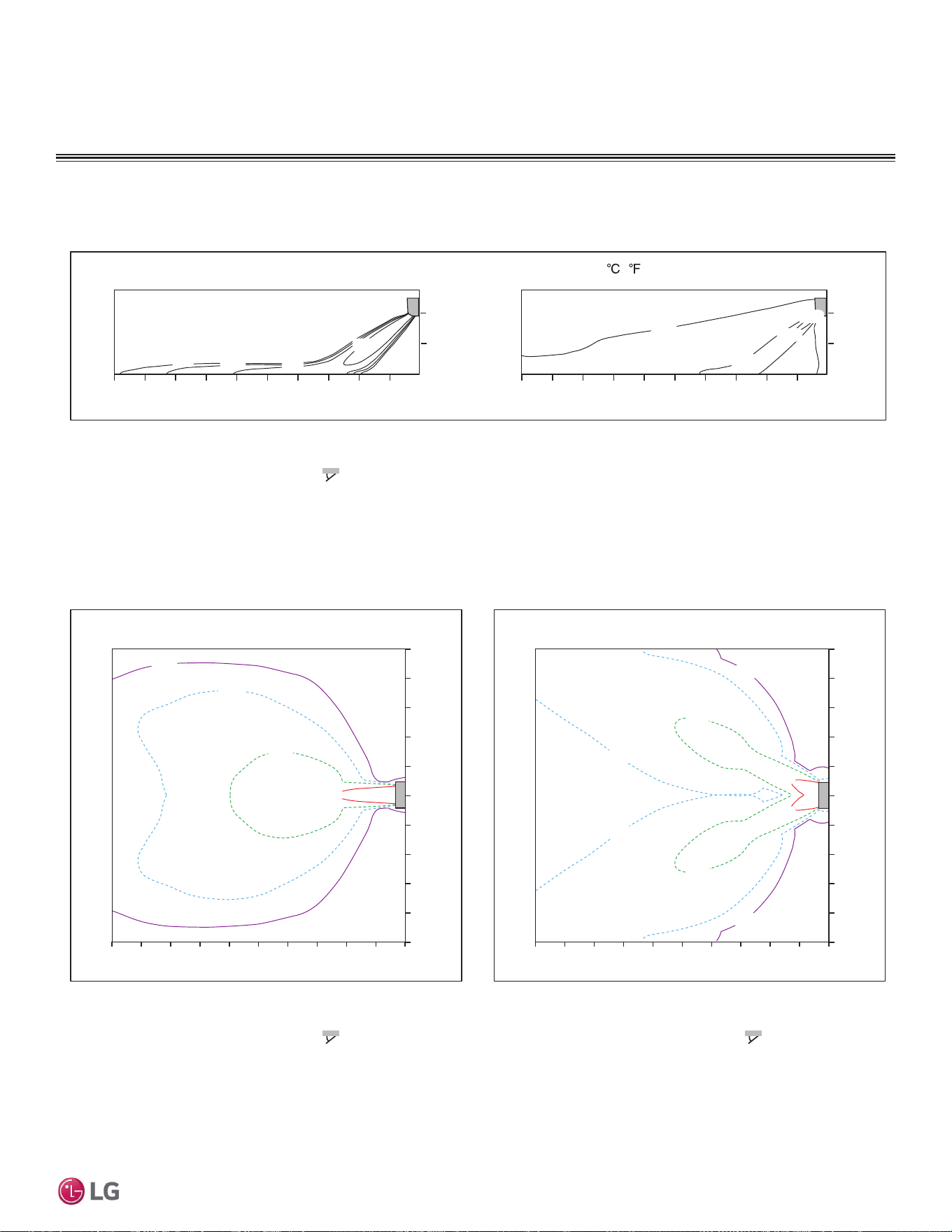
AIR FLOW AND TEMPERATURE DISTRIBUTION
LSN090HEV2, continued.
Heating
26(79)
24(75)
22(72)
2(6.6)
1(3.3)
0.5(1.6)
0.3(1)
1
Air Velocity [m/s (ft./s)]
0
0
10
2
2468
m
m
06.6
ft.
32.8 13.119.726.2
1
0
0
10
2
2468
m
3.3
mft.
0
6.6
ft.
3.3
0
6.6
0
ft.
32.8 6.613.119.726.2
28(82)
0.3(1)
0.5(1.6)
1(3.3)
1(3.3)
1(3.3)
2(6.6)
0.3(1)
0.3(1)
0.5(1.6)
0.5(1.6)
2(6.6)
2(6.6)
0
Air Velocity [m/s (ft./s)]
m
10 2468
m
1
0
1
2
3
4
3
2
4
5
5
0
Air Velocity [m/s (ft./s)]
10 2468
m
1
0
1
2
3
4
3
2
4
5
5
06.6
ft.
32.8 13.119.726.2 032.8 6.613.119.726.2
m
ft.
ft.
3.3
0
3.3
6.6
9.8
13.1
9.8
6.6
13.1
16.4
16.4
3.3
3.3
6.6
9.8
13.1
9.8
6.6
13.1
16.4
16.4
ft.
0
Side View
Discharge $QJOHÛ)URPWKHIORRU )
Vertical Louver : Center
)DQ6SHHG3RZHU
TRSView
Discharge $QJOHÛ)URPWKHIORRU )
Vertical Louver : Center
)DQ6SHHG3RZHU
$LU6SHHGPVIWV5DQJHPIW
TRSView
Discharge $QJOHÛ)URPWKHIORRU )
VHUWLFDO/RXYHU/HIW5LJKW
)DQ6SHHG3RZHU
THPSHUDWXUH> ( )]
40 | PRODUCT DATA
Single Zone Mega Wall Mounted Engineering Manual
'XHWRRXUSROLF\RIFRQWLQXRXVSURGXFWLQQRYDWLRQVRPHVSHFL¿FDWLRQVPD\FKDQJHZLWKRXWQRWL¿FDWLRQ
©
/*(OHFWURQLFV86$,QF(QJOHZRRG&OLIIV1-$OOULJKWVUHVHUYHG³/*´LVDUHJLVWHUHGWUDGHPDUNRI/*&RUS
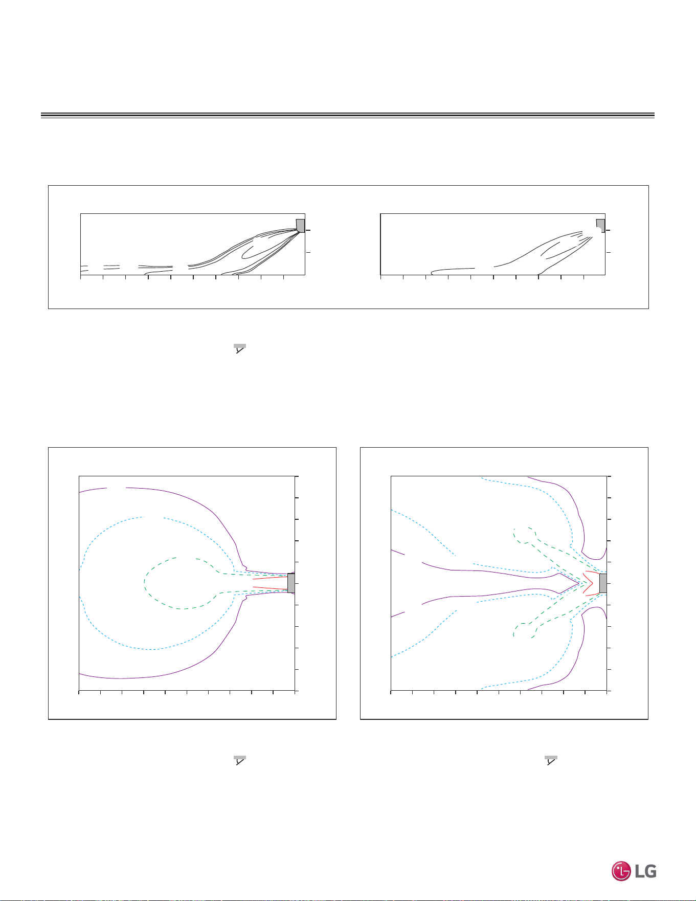
AIR FLOW AND TEMPERATURE DISTRIBUTION
LSN120HEV2
Cooling
0.3(1)
0.5(1.6)
1(3.3)
2(6.6)
Air Velocity [m/s (ft./s)]
1
0
0
10
2
2468
m
m
06.6
ft.
32.8 13.119.726.2
1
0
0
10
2
2468
m
3.3
mft.
0
6.6
ft.
3.3
0
6.6
06.6
ft.
32.8 13.119.726.2
28(82)
26(79)
24(75)
22(72)
0.3(1)
0.5(1.6)
1(3.3)
1(3.3)
1(3.3)
2(6.6)
0.3(1)
0.3(1)
0.5(1.6)
0.5(1.6)
2(6.6)
2(6.6)
Air Velocity [m/s (ft./s)]
02
m
10 468
m
1
0
1
2
3
4
3
2
4
5
5
0
Air Velocity [m/s (ft./s)]
10 2468
m
1
0
1
2
3
4
3
2
4
5
5
0
ft.
32.8 6.613.119.726.2 032.8 6.613.119.726.2
m
ft.
ft.
3.3
0
3.3
6.6
9.8
13.1
9.8
6.6
13.1
16.4
16.4
3.3
3.3
6.6
9.8
13.1
9.8
6.6
13.1
16.4
16.4
ft.
0
Side View
Discharge $QJOHÛ)URPWKHIORRU )
Vertical Louver : Center
)DQ6SHHG3RZHU
TRSView
Discharge $QJOHÛ)URPWKHIORRU )
Vertical Louver : Center
)DQ6SHHG3RZHU
$LU6SHHGPVIWV5DQJHPIW
TRSView
Discharge $QJOHÛ)URPWKHIORRU )
VHUWLFDO/RXYHU/HIW5LJKW
)DQ6SHHG3RZHU
THPSHUDWXUH>Û&Û)@
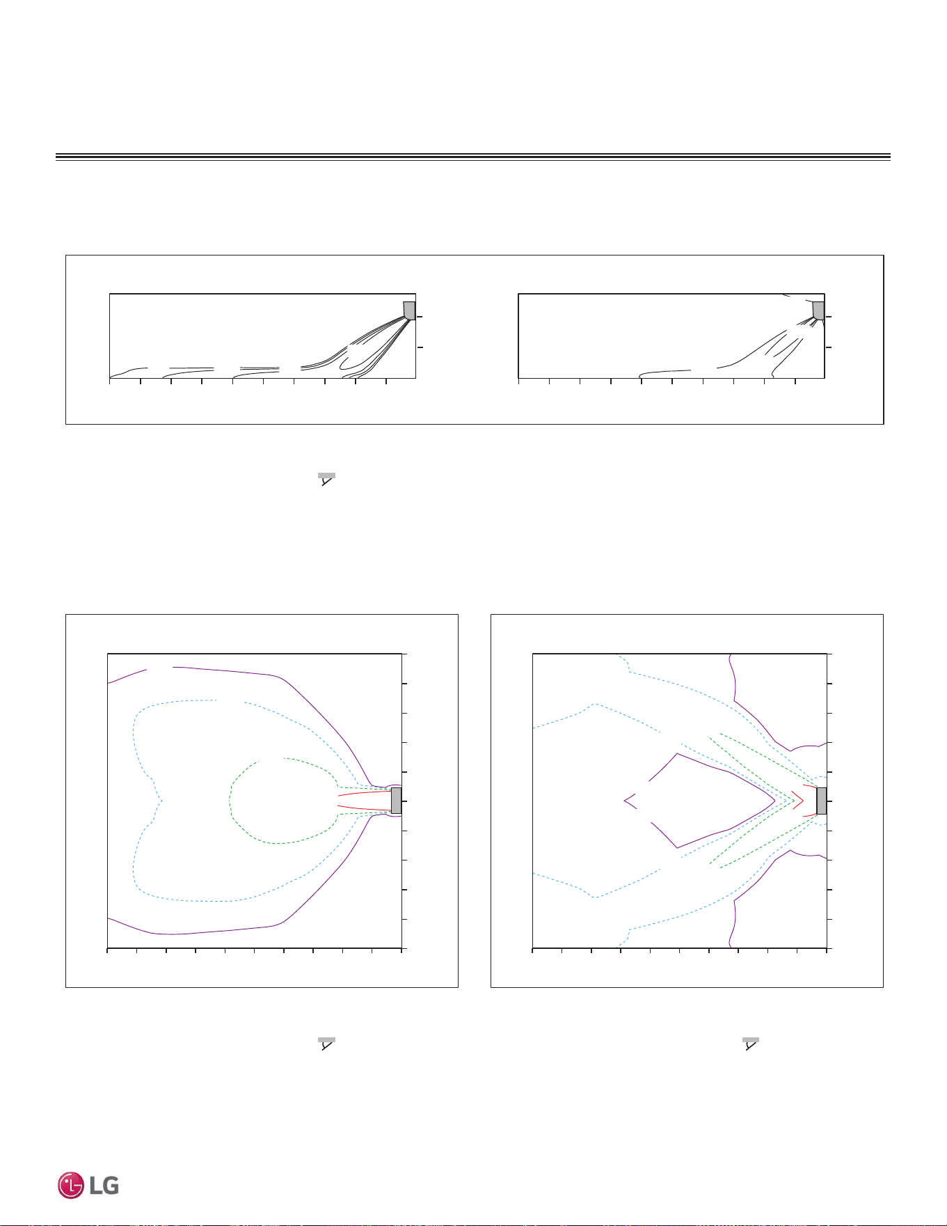
PRODUCT DATA | 41
Product Data
'XHWRRXUSROLF\RIFRQWLQXRXVSURGXFWLQQRYDWLRQVRPHVSHFL¿FDWLRQVPD\FKDQJHZLWKRXWQRWL¿FDWLRQ
©
/*(OHFWURQLFV86$,QF(QJOHZRRG&OLIIV1-$OOULJKWVUHVHUYHG³/*´LVDUHJLVWHUHGWUDGHPDUNRI/*&RUS
AIR FLOW AND TEMPERATURE DISTRIBUTION
LSN120HEV2, continued.
Heating
Temperature [Û&Û)@
Air VHORFLW\>PVIWV@
1
0
0
10
2
2468
m
m
0
IW
86612
1
0
0
10
2
2468
m
0
m IW
IW
0
0
IW
8661262
Air VHORFLW\>PVIWV@
0
m
10 2468
m
1
0
1
2
4
2
4
Air VHORFLW\>PVIWV@
010 2468
m
1
0
1
2
4
2
4
066
IW
8 12 08661262
m
IW
IW
0
8
1
8
1
8
1
8
1
IW
0
Side View
Discharge $QJOHÛ)URPWKHIORRU
VHUWLFDO/RXYHU&HQWHU
)DQ6SHHG3RZHU
Top View
Discharge $QJOHÛ)URPWKHIORRU
VHUWLFDO/RXYHU&HQWHU
)DQ6SHHG3RZHU
$LU6SHHGPVIWV5DQJHPIW
Top View
Discharge $QJOHÛ)URPWKHIORRU
VHUWLFDO/RXYHU/HIW5LJKW
)DQ6SHHG3RZHU
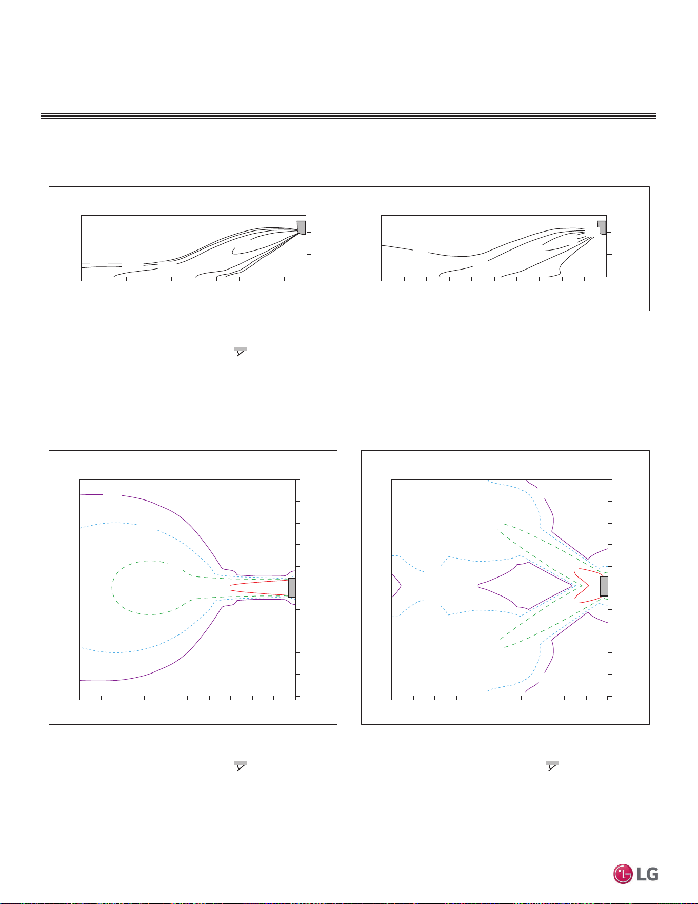
42 | PRODUCT DATA
Single Zone Mega Wall Mounted Engineering Manual
'XHWRRXUSROLF\RIFRQWLQXRXVSURGXFWLQQRYDWLRQVRPHVSHFL¿FDWLRQVPD\FKDQJHZLWKRXWQRWL¿FDWLRQ
©
/*(OHFWURQLFV86$,QF(QJOHZRRG&OLIIV1-$OOULJKWVUHVHUYHG³/*´LVDUHJLVWHUHGWUDGHPDUNRI/*&RUS
LSN180HEV2
AIR FLOW AND TEMPERATURE DISTRIBUTION
Cooling
Temperature [ഒ (ഘ)]
2(6.6)
0.3(1)
1(3.3)
Air Velocity [m/s (ft./s)]
1
0
0
10
2
2468
m
m
06.6
ft.
32.8 13.119.726.2
1
0
0
10
2
2468
m
3.3
0
mft.
6.6
ft.
3.3
0
6.6
06.6
ft.
32.8 13.119.726.2
22(72)
24(75)
26(79)
28(82)
20(68)
0.3(1)
0.5(1.6)
1(3.3)
2(6.6)
2(6.6)
2(6.6)
1(3.3)
1(3.3)
0.5(1.6)
0.5(1.6)
0.3(1)
0.3(1)
Air Velocity [m/s (ft./s)]
0
m
10 2468
m
1
0
1
2
3
4
3
2
4
5
5
Air Velocity [m/s (ft./s)]
010 2468
m
1
0
1
2
3
4
3
2
4
5
5
0
ft.
32.8 6.613.119.726.2 032.8 6.613.119.726.2
m
ft.
ft.
3.3
0
3.3
6.6
9.8
13.1
9.8
6.6
13.1
16.4
16.4
3.3
3.3
6.6
9.8
13.1
9.8
6.6
13.1
16.4
16.4
ft.
0
Side View
Discharge $QJOHÛ)URPWKHIORRU )
Vertical Louver : Center
)DQ6SHHG3RZHU
Top View
Discharge $QJOHÛ)URPWKHIORRU )
Vertical Louver : Center
)DQ6SHHG3RZHU
Air Speed 0.3 m/s (1 ft./s) Range : 15.8 m (51.8 ft.)
Top View
Discharge $QJOHÛ)URPWKHIORRU )
Vertical Louver : Left & Right
)DQ6SHHG3RZHU
0.5(1.6)
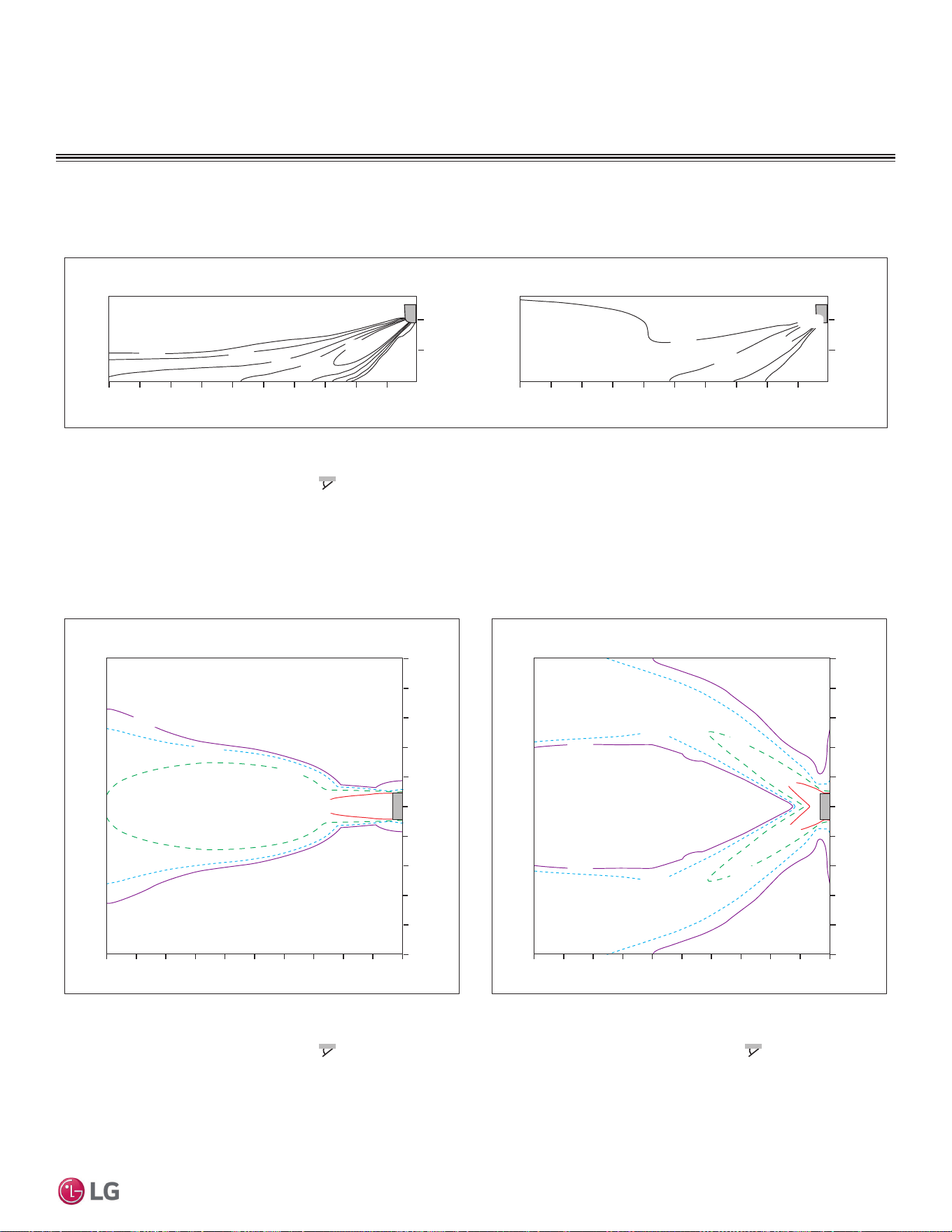
PRODUCT DATA | 43
Product Data
'XHWRRXUSROLF\RIFRQWLQXRXVSURGXFWLQQRYDWLRQVRPHVSHFL¿FDWLRQVPD\FKDQJHZLWKRXWQRWL¿FDWLRQ
©
/*(OHFWURQLFV86$,QF(QJOHZRRG&OLIIV1-$OOULJKWVUHVHUYHG³/*´LVDUHJLVWHUHGWUDGHPDUNRI/*&RUS
AIR FLOW AND TEMPERATURE DISTRIBUTION
LSN180HEV2, continued.
Heating
24(75)
26(79)
28(82)
1
Air Velocity [m/s (ft./s)]
0
0
10
2
2468
m
m
0
ft.
32.8 6.613.119.726.2
1
0
0
10
2
2468
m
3.3
0
mft.
6.6
ft.
3.3
0
6.6
06.6
ft.
32.8 13.119.726.2
0.3(1)
0.5(1.6)
1(3.3)
2(6.6)
1.5(4.9)
32(90)
0.3(1)
0.5(1.6)
1(3.3)
2(6.6)
0.5(1.6)
0.5(1.6)
1(3.3)
1(3.3)
0.3(1)
0.3(1)
2(6.6)
2(6.6)
Air Velocity [m/s (ft./s)]
02
m
10 468
m
1
0
1
2
3
4
3
2
4
5
5
Air Velocity [m/s (ft./s)]
010 2468
m
1
0
1
2
3
4
3
2
4
5
5
0
ft.
32.8 6.613.119.726.2 032.8 6.613.119.726.2
m
ft.
ft.
3.3
0
3.3
6.6
9.8
13.1
9.8
6.6
13.1
16.4
16.4
3.3
3.3
6.6
9.8
13.1
9.8
6.6
13.1
16.4
16.4
ft.
0
Side View
Discharge $QJOHÛ)URPWKHIORRU )
Vertical Louver : Center
)DQ6SHHG3RZHU
TRSView
Discharge $QJOHÛ)URPWKHIORRU )
Vertical Louver : Center
)DQ6SHHG3RZHU
$LU6SHHGPVIWV5DQJHPIW
TRSView
Discharge $QJOHÛ)URPWKHIORRU )
VHUWLFDO/RXYHU/HIW5LJKW
)DQ6SHHG3RZHU
THPSHUDWXUH>ഒ (ഘ)]
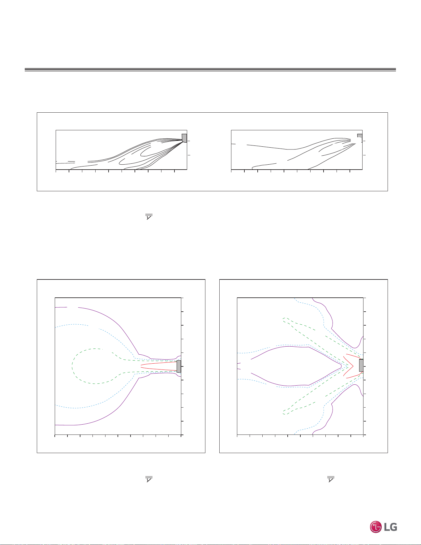
44 | PRODUCT DATA
Single Zone Mega Wall Mounted Engineering Manual
'XHWRRXUSROLF\RIFRQWLQXRXVSURGXFWLQQRYDWLRQVRPHVSHFL¿FDWLRQVPD\FKDQJHZLWKRXWQRWL¿FDWLRQ
©
/*(OHFWURQLFV86$,QF(QJOHZRRG&OLIIV1-$OOULJKWVUHVHUYHG³/*´LVDUHJLVWHUHGWUDGHPDUNRI/*&RUS
AIR FLOW AND TEMPERATURE DISTRIBUTION
LSN240HEV2
Cooling
2(6.6)
0.3(1)
1(3.3)
1
Air Velocity [m/s (ft./s)]
0
0
10
2
2468
m
m
0
ft.
32.8 6.613.119.726.2
1
0
0
10
2
2468
m
3.3
0
mft.
6.6
ft.
3.3
0
6.6
0
ft.
32.8 6.613.119.726.2
1.5(4.9)
0.5(1.6)
28(82)
26(79)
24(75)
22(72)
18(64)
0.3(1)
0.5(1.6)
1(3.3)
2(6.6)
2(6.6)
2(6.6)
1(3.3)
1(3.3)
0.5(1.6)
0.5(1.6)
0.3(1)
0.3(1)
0
Air Velocity [m/s (ft./s)]
2
m
10 468
m
1
0
1
2
3
4
3
2
4
5
5
0
Air Velocity [m/s (ft./s)]
10 2468
m
1
0
1
2
3
4
3
2
4
5
5
06.6
ft.
32.8 13.119.726.2 032.8 6.613.119.726.2
m
ft.
ft.
3.3
0
3.3
6.6
9.8
13.1
9.8
6.6
13.1
16.4
16.4
3.3
3.3
6.6
9.8
13.1
9.8
6.6
13.1
16.4
16.4
ft.
0
Side View
Discharge $QJOHÛ)URPWKHIORRU )
Vertical Louver : Center
)DQ6SHHG3RZHU
TRSView
Discharge $QJOHÛ)URPWKHIORRU )
Vertical Louver : Center
)DQ6SHHG3RZHU
$LU6SHHGPVIWV5DQJHPIW
TRSView
Discharge $QJOHÛ)URPWKHIORRU )
VHUWLFDO/RXYHU/HIW5LJKW
)DQ6SHHG3RZHU
THPSHUDWXUH>Û&Û)@
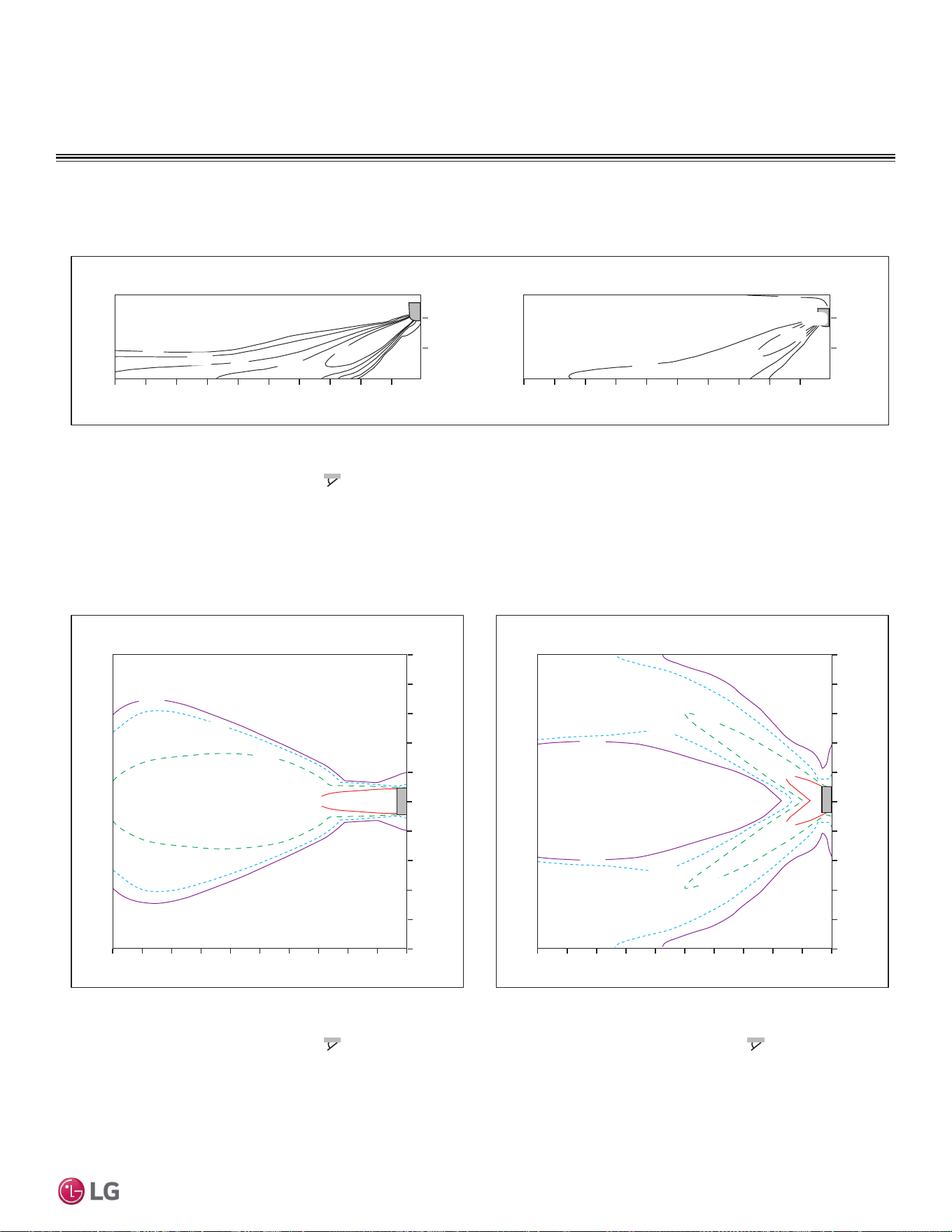
PRODUCT DATA | 45
Product Data
'XHWRRXUSROLF\RIFRQWLQXRXVSURGXFWLQQRYDWLRQVRPHVSHFL¿FDWLRQVPD\FKDQJHZLWKRXWQRWL¿FDWLRQ
©
/*(OHFWURQLFV86$,QF(QJOHZRRG&OLIIV1-$OOULJKWVUHVHUYHG³/*´LVDUHJLVWHUHGWUDGHPDUNRI/*&RUS
AIR FLOW AND TEMPERATURE DISTRIBUTION
LSN240HEV2, continued.
Heating
24(75)
26(79)
28(82)
30(86)
0.3(1)
0.5(1.6)
1(3.3)
1.5(4.9)
2(6.6)
Air Velocity [m/s (ft./s)]
1
0
0
10
2
2468
m
m
0
ft.
32.8 6.613.119.726.2
1
0
0
10
2
2468
m
3.3
0
mft.
6.6
ft.
3.3
0
6.6
06.6
ft.
32.8 13.119.726.2
32(90)
0
Air Velocity [m/s (ft./s)]
2
m
10 468
m
1
0
1
2
3
4
3
2
4
5
5
Air Velocity [m/s (ft./s)]
010 2468
m
1
0
1
2
3
4
3
2
4
5
5
0
ft.
32.8 6.613.119.726.2 032.8 6.613.119.726.2
m
ft.
ft.
3.3
0
3.3
6.6
9.8
13.1
9.8
6.6
13.1
16.4
16.4
3.3
3.3
6.6
9.8
13.1
9.8
6.6
13.1
16.4
16.4
ft.
0
0.3(1)
0.3(1)
0.5(1.6)
0.5(1.6)
1(3.3)
1(3.3)
2(6.6)
2(6.6)
0.3(1)
0.5(1.6)
1(3.3)
2(6.6)
Side View
Discharge $QJOHÛ)URPWKHIORRU )
Vertical Louver : Center
)DQ6SHHG3RZHU
TRSView
Discharge $QJOHÛ)URPWKHIORRU )
Vertical Louver : Center
)DQ6SHHG3RZHU
$LU6SHHGPVIWV5DQJHPIW
TRSView
Discharge $QJOHÛ)URPWKHIORRU )
VHUWLFDO/RXYHU/HIW5LJKW
)DQ6SHHG3RZHU
THPSHUDWXUH>ഒ (ഘ)]
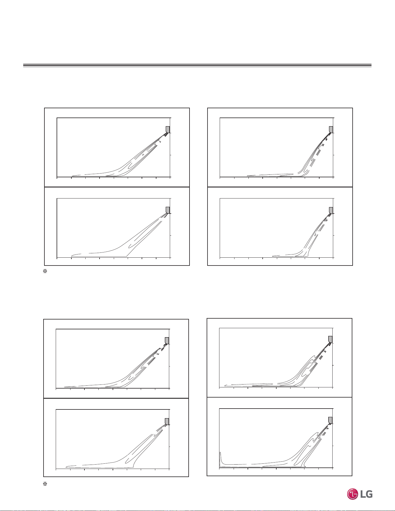
46 | PRODUCT DATA
Single Zone Mega Wall Mounted Engineering Manual
'XHWRRXUSROLF\RIFRQWLQXRXVSURGXFWLQQRYDWLRQVRPHVSHFL¿FDWLRQVPD\FKDQJHZLWKRXWQRWL¿FDWLRQ
©
/*(OHFWURQLFV86$,QF(QJOHZRRG&OLIIV1-$OOULJKWVUHVHUYHG³/*´LVDUHJLVWHUHGWUDGHPDUNRI/*&RUS
LSN090HXV
LSN120HXV
AIR FLOW AND TEMPERATURE DISTRIBUTION
Cooling
Discharge angle: 45°
Heating
Discharge angle: 50°
Air velocity [ft/s]
Temperature [°F]
6.6ft
3.3ft
0ft
26.2ft 13.1ft 9.8ft 6.6ft 3.3ft
0ft
16.4ft19.7ft23.0ft
6.6ft
3.3ft
0ft
26.2ft 13.1ft 9.8ft 6.6ft 3.3ft
0ft
16.4ft19.7ft23.0ft
3.3
73.4
69.8
66.2
11
.5
9.8
8.2
4.9
6.6
Air velocity [ft/s]
Temperature [°F]
3.3
98.6
91.4
87.8
84.2
80.6
11.5
13.1
9.8
8.2
4.9
6.6
6.6ft
3.3ft
0ft
26.2ft 13.1ft 9.8ft 6.6ft 3.3ft
0ft
16.4ft19.7ft23.0ft
6.6ft
3.3ft
0ft
26.2ft 13.1ft 9.8ft 6.6ft 3.3ft
0ft
16.4ft19.7ft23.0ft
Air velocity [ft/s]
Temperature [°F]
64.4
66.2
69.8
73.4
8.2
13.1
11
.5
9.8
8.2
6.6
4.9
3.3
6.6ft
3.3ft
0ft
26.2ft 13.1ft 9.8ft 6.6ft 3.3ft
0ft
16.4ft19.7ft23.0ft
6.6ft
3.3ft
0ft
26.2ft 13.1ft 9.8ft 6.6ft 3.3ft
0ft
16.4ft19.7ft23.0ft
Air velocity [ft/s]
Temperature [°F]
3.3
4.9
86
93.2
89.6
86
82.4
78.8
11
.5
13.1
9.8
8.2
6.6
6.6ft
3.3ft
0ft
26.2ft 13.1ft 9.8ft 6.6ft 3.3ft
0ft
16.4ft19.7ft23.0ft
6.6ft
3.3ft
0ft
26.2ft 13.1ft 9.8ft 6.6ft 3.3ft
0ft
16.4ft19.7ft23.0ft
Cooling
Discharge angle: 45°
Heating
Discharge angle: 50°
Based on maximum air flow.
Based on maximum air flow.
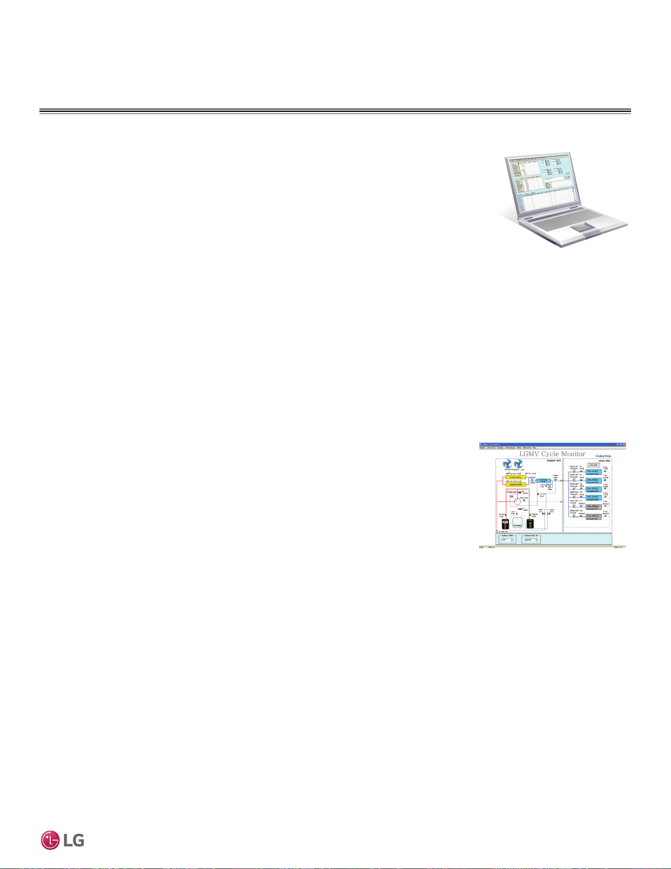
PRODUCT DATA | 47
Product Data
'XHWRRXUSROLF\RIFRQWLQXRXVSURGXFWLQQRYDWLRQVRPHVSHFL¿FDWLRQVPD\FKDQJHZLWKRXWQRWL¿FDWLRQ
©
/*(OHFWURQLFV86$,QF(QJOHZRRG&OLIIV1-$OOULJKWVUHVHUYHG³/*´LVDUHJLVWHUHGWUDGHPDUNRI/*&RUS
ACCESSORIES
• Actual inverter compressor speed
• Target inverter compressor speed
• Actual outdoor fan speed
• Target outdoor unit fan speed
• Actual superheat
• Target superheat
• Actual subcooler circuit superheat
• Target subcooler circuit superheat
• Main EEV position
• Subcooling EEV position
• Inverter compressor current transducer
value
• Outdoor air temperature
• Actual high pressure/saturation temperature
• Actual low pressure/saturation temperature
• Suction temperature
• Inverter compressor discharge temperature
• Constant speed compressor discharge
temperature
• Front outdoor coil pipe temperature
• Back outdoor coil pipe temperature
• Liquid line pipe temperature
• Subcooler inlet temperature
• Subcooler outlet temperature
• Average indoor unit (IDU) pipe temperature
• Inverter compressor operation indicator
light
• Four-way reversing valve operation
indicator light
• Pressure graph showing actual low pres-
sure and actual high pressure levels
• Error code display
• Operating mode indicator
• Target high pressure
• Target low pressure
• PCB (printed circuit board) version
• Software
version
• Installer
name
• Model no.
of outdoor units
• Site name
• Total number of connected indoor units
• Communication indicator lights
• Indoor unit capacity
• Indoor unit operating mode
• Indoor unit fan speed
• Indoor unit EEV position
• Indoor unit room temperature
• Indoor unit inlet pipe temperature
• Indoor unit outlet pipe temperature
• Indoor unit error code
LG Monitoring View (LGMV) Diagnostic Software and Cable
LGMV software allows the service technician or commissioning agent to connect a computer USB port
to the outdoor unit main printed circuit board (PCB) using an accessory cable without the need for a
separate interface device. The main screen for LGMV allows user to view the following real time data on
one screen:
Additional screens can be accessed by tabs on the main screen:
1. Cycleview: Graphic of internal components including:
2. Graph: Full screen graph of actual high and low pressures and high and low pressure limits. A slid-
ing bar enables user to go back in time and view data.
3. Control IDU: Enables user to turn on all IDU’s default setpoints of 86°F in heat mode or 64°F in
cool mode.
4. Setting: Converts metric values to imperial values.
5. Making Data: Recording of real time data to a separate file created to be stored on the user’s computer.
6. Loading Data: Recorded data from a saved “.CSV” file can be loaded to create an LGMV session.
7. Electrical Data: The lower half of main screen is changed to show the following:
Figure 26: Sample Cycleview.
• Compressors showing actual speeds
• EEVs
• Indoor Units
• Liquid injection valves
• Temperature and pressure sensors
• Four-way reversing valve
• Outdoor fans showing status and speeds
• Inverter compressor
- Amps
- Volts
- Power Hz
- Inverter control board fan Hz
• Constant compressor
- Current transducer value
- Phase
• CPU: Pentium
®
IV 1.6 GHz
• Operating System: Windows
®
NT/2000/XP/Vista
• Main Memory: 256 MB
• Hard Disk: 600 MB when operating
• Web Browser: Internet Explorer
®
5.0
/*09LVDYDLODEOHLQGLႇHUHQWIRUPDWVLQFOXGLQJ0RELOH/*09ZKLFKLVDDSSIRUXVHRQZLUHOHVVGHYLFHV&RQWDFW\RXU/*
Sales Representative for more information.
In lieu of connecting to the outdoor unit, user has the option to connect to the indoor unit with the use of a USB to RS-485 connector kit.
When connected through the indoor unit, user will not be able to record data.
This software can be used to both commission new systems and troubleshoot existing systems. LGMV data can be recorded to a “.CSV” file
and emailed to an LG representative to assist with diagnostic evaluations.
Recommended Minimum PC Configuration:
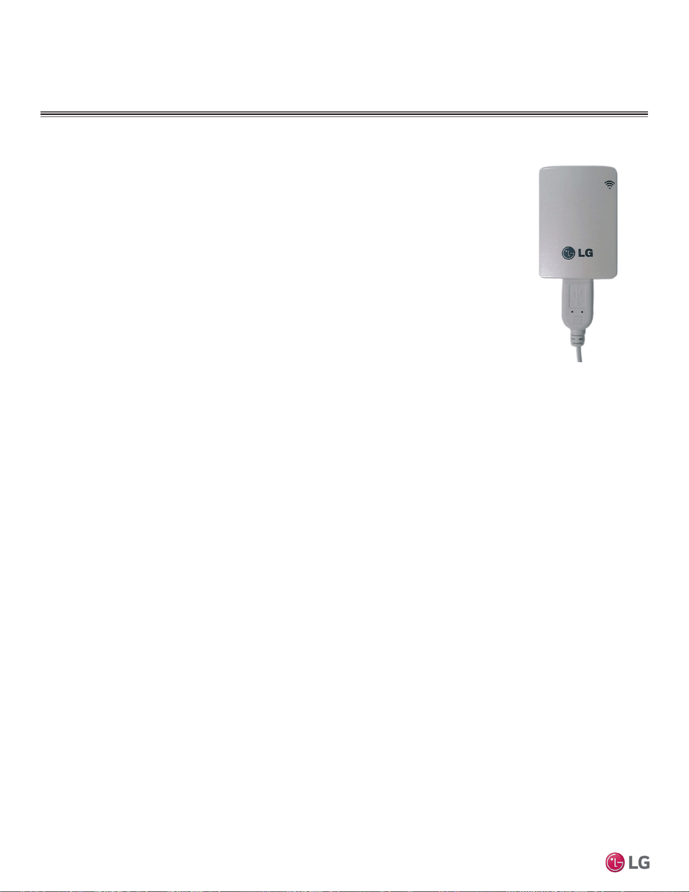
48 | PRODUCT DATA
Single Zone Mega Wall Mounted Engineering Manual
'XHWRRXUSROLF\RIFRQWLQXRXVSURGXFWLQQRYDWLRQVRPHVSHFL¿FDWLRQVPD\FKDQJHZLWKRXWQRWL¿FDWLRQ
©
/*(OHFWURQLFV86$,QF(QJOHZRRG&OLIIV1-$OOULJKWVUHVHUYHG³/*´LVDUHJLVWHUHGWUDGHPDUNRI/*&RUS
ACCESSORIES
Contact your LG Sales Representative for system requirements, the latest version of SIMS,
how to download the app, or other information.
Figure 27: LG SIMS WLAN
Module.
LG Smart Inverter Monitoring System (SIMS)
SIMS can be used to display and graph operational data for single zone systems and respective com-
ponents (indoor unit and outdoor unit). SIMS also displays error codes and a troubleshooting guide.
SIMs consists of a hardware Wireless Local Area Network (WLAN) module, an interface cable, and a
free downloadable application (app) for iOS® or Android™. The user must supply either an Apple® or an
Android smart phone; SIMs is not optimized for tablets, and only be used with LG single zone and Multi F
systems.
Only trained HVAC service technicians familiar with variable refrigerant flow (VRF) systems in general
and with LG’s DFS products can use SIMS. The technician must understand inverter air conditioning
operation cycles, the meaning of the data displayed by SIMS, and how to use the data to troubleshoot
the system.
iOS is a registered trademark of Cisco in the U.S. and other countries. Android is a trademark of Google Inc.
Apple is a trademark of Apple Inc., registered in the U.S. and other countries.

PERFORMANCE DATA
Cooling Capacity Data on page 50
Heating Capacity Data on page 53
Maximum Heating Capacity Data on page 55
Equipment Selection Procedure on page 57
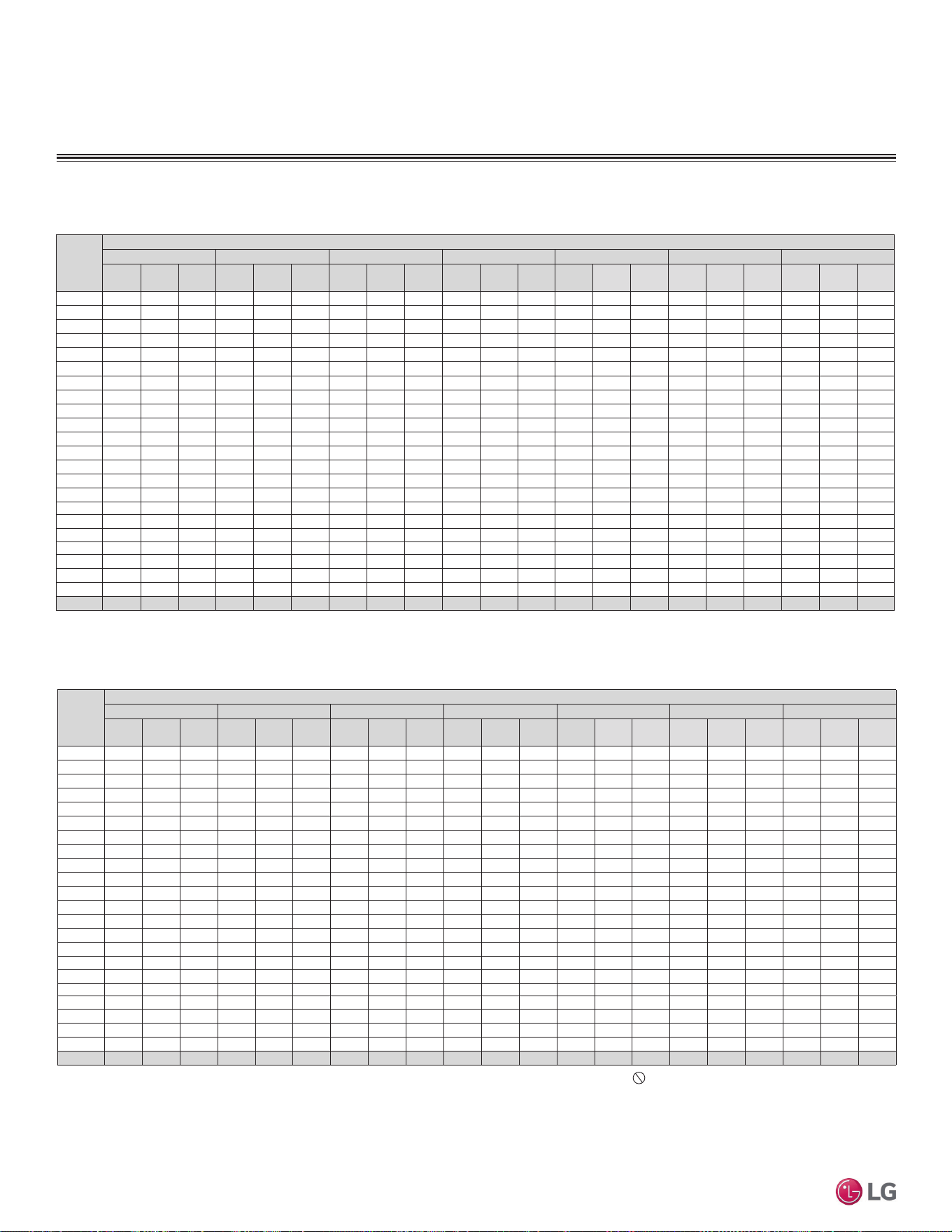
'XHWRRXUSROLF\RIFRQWLQXRXVSURGXFWLQQRYDWLRQVRPHVSHFL¿FDWLRQVPD\FKDQJHZLWKRXWQRWL¿FDWLRQ
©
/*(OHFWURQLFV86$,QF(QJOHZRRG&OLIIV1-$OOULJKWVUHVHUYHG³/*´LVDUHJLVWHUHGWUDGHPDUNRI/*&RUS
50 | PERFORMANCE DATA
Single Zone Mega Wall Mounted Engineering Manual
PERFORMANCE DATA
Table 15: LSN090HEV2 / LSU120HEV2 Cooling Capacities.
Outdoor
Air
Temp.
(°F DB)
Indoor Air Temperature (°F DB/ °F WB)
64 / 53 68 / 57 72 / 61 77 / 64 80 / 67 86 / 72 90 / 75
TC SHC PI TC SHC PI TC SHC PI TC SHC PI TC SHC PI TC SHC PI TC SHC PI
14 5.51 4.90 0.31 6.89 5.21 0.36 8.27 5.53 0.42 9.99 5.93 0.49 11.03 6.17 0.53 9.20 6.73 0.43 7.99 7.10 0.37
23 5.92 5.26 0.30 7.12 5.60 0.37 8.32 5.94 0.43 9.82 6.36 0.51 10.72 6.62 0.56 9.43 7.22 0.44 8.57 7.62 0.37
25 6.01 5.34 0.31 7.18 5.67 0.37 8.36 6.00 0.43 9.83 6.41 0.51 10.71 6.66 0.56 9.54 7.30 0.45 8.75 7.72 0.38
30 6.24 5.55 0.33 7.35 5.85 0.39 8.46 6.16 0.45 9.85 6.54 0.52 10.68 6.77 0.56 9.80 7.49 0.47 9.20 7.97 0.41
35 6.47 5.75 0.36 7.52 6.03 0.41 8.56 6.31 0.46 9.87 6.67 0.53 10.66 6.88 0.57 10.05 7.69 0.49 9.65 8.23 0.43
40 6.70 5.96 0.38 7.69 6.22 0.43 8.67 6.47 0.48 9.90 6.79 0.54 10.63 6.98 0.57 10.31 7.88 0.50 10.10 8.48 0.46
45 6.94 6.17 0.40 7.85 6.40 0.45 8.77 6.63 0.49 9.92 6.92 0.54 10.61 7.09 0.58 10.57 8.07 0.52 10.55 8.73 0.49
50 7.17 6.37 0.43 8.02 6.58 0.46 8.88 6.78 0.50 9.94 7.04 0.55 10.58 7.20 0.58 10.83 8.27 0.54 11.00 8.98 0.51
55 7.40 6.58 0.45 8.19 6.76 0.48 8.98 6.94 0.52 9.96 7.17 0.56 10.56 7.30 0.58 11.09 8.46 0.56 11.45 9.24 0.54
60 7.63 6.79 0.47 8.36 6.94 0.50 9.08 7.10 0.53 9.99 7.29 0.57 10.53 7.41 0.59 11.35 8.66 0.58 11.90 9.49 0.57
65 7.56 6.72 0.49 8.25 6.91 0.52 8.94 7.10 0.55 9.80 7.34 0.59 10.31 7.48 0.61 11.13 8.66 0.60 11.68 9.45 0.60
70 7.49 6.66 0.52 8.14 6.89 0.55 8.79 7.11 0.57 9.61 7.39 0.61 10.09 7.55 0.63 10.91 8.67 0.63 11.46 9.41 0.63
75 7.43 6.60 0.54 8.04 6.86 0.57 8.65 7.11 0.59 9.42 7.43 0.63 9.87 7.62 0.65 10.69 8.67 0.65 11.24 9.37 0.66
80 7.36 6.54 0.57 7.93 6.83 0.59 8.51 7.12 0.62 9.22 7.48 0.65 9.66 7.70 0.66 10.48 8.68 0.68 11.02 9.33 0.69
85 7.29 6.48 0.59 7.82 6.80 0.61 8.36 7.12 0.64 9.03 7.53 0.67 9.44 7.77 0.68 10.26 8.68 0.70 10.80 9.29 0.71
90 7.22 6.42 0.61 7.72 6.77 0.64 8.22 7.13 0.66 8.84 7.57 0.68 9.22 7.84 0.70 10.04 8.69 0.73 10.58 9.25 0.74
95 7.15 6.36 0.64 7.61 6.75 0.66 8.07 7.13 0.68 8.65 7.62 0.70 9.00 7.91
0.72 9.82 8.69 0.75 10.36 9.21 0.77
100 6.96 6.19 0.65 7.43 6.60 0.67 7.91 7.00 0.69 8.50 7.51 0.72 8.86 7.82 0.73 9.65 8.55 0.76 10.17 9.05 0.78
105 6.77 6.02 0.66 7.26 6.45 0.68 7.75 6.87 0.70 8.35 7.40 0.73 8.72 7.72 0.74 9.48 8.42 0.77 9.99 8.88 0.80
110 6.59 5.86 0.67 7.08 6.30 0.69 7.58 6.74 0.71 8.21 7.29 0.74 8.58 7.63 0.75 9.31 8.28 0.78 9.80 8.71 0.81
115 6.35 5.65 0.67 6.83 6.08 0.70 7.32 6.51 0.72 7.92 7.05 0.74 8.28 7.37 0.76 8.99 8.00 0.79 9.47 8.42 0.82
118 6.21 5.52 0.68 6.68 5.94 0.70 7.16 6.37 0.72 7.75 6.90 0.75 8.10 7.22 0.77 8.80 7.83 0.80 9.27 8.24 0.82
122 6.02 5.63 0.69 6.48 6.06 0.71 6.94 6.50 0.73 7.51 7.04 0.76 7.86 7.36 0.77 8.54 7.99 0.81 8.99 8.41 0.83
Table 16: LSN120HEV2 / LSU120HEV2 Cooling Capacities.
Outdoor
Air
Temp.
(°F DB)
Indoor Air Temperature (°F DB/ °F WB)
64 / 53 68 / 57 72 / 61 77 / 64 80 / 67 86 / 72 90 / 75
TC SHC PI TC SHC PI TC SHC PI TC SHC PI TC SHC PI TC SHC PI TC SHC PI
14 7.35 5.65 0.49 9.19 6.02 0.58 11.03 6.39 0.67 13.33 6.84 0.78 14.71 7.12 0.84 12.27 7.76 0.69 10.65 8.19 0.58
23 7.89 6.07 0.48 9.49 6.46 0.58 11.09 6.86 0.68 13.09 7.35 0.81 14.29 7.64 0.88 12.58 8.34 0.70 11.43 8.80 0.58
25 8.01 6.17 0.49 9.58 6.55 0.59 11.14 6.93 0.69 13.10 7.40 0.81 14.28 7.69 0.89 12.71 8.42 0.71 11.67 8.91 0.60
30 8.32 6.40 0.53 9.80 6.76 0.62 11.28 7.11 0.71 13.13 7.55 0.82 14.24 7.81 0.89 13.06 8.65 0.74 12.27 9.21 0.64
35 8.63 6.64 0.57 10.03 6.97 0.65 11.42 7.29 0.73 13.16 7.69 0.84 14.21 7.94 0.90 13.41 8.87 0.77 12.87 9.50 0.69
40 8.94 6.88 0.60 10.25 7.18 0.68 11.56 7.47 0.75 13.19 7.84 0.85 14.18 8.06 0.91 13.75 9.10 0.80 13.47 9.79 0.73
45 9.25 7.12 0.64 10.47 7.38 0.71 11.70 7.65 0.78 13.22 7.98 0.86 14.14 8.18 0.91 14.10 9.32 0.83 14.07 10.08 0.77
50 9.56 7.36 0.67 10.70 7.59 0.74 11.83 7.83 0.80 13.25 8.13 0.87 14.11 8.31 0.92 14.44 9.54 0.86 14.67 10.37 0.82
55 9.87 7.60 0.71 10.92 7.80 0.76 11.97 8.01 0.82 13.29 8.27 0.89 14.07 8.43 0.93 14.79 9.77 0.89 15.27 10.66 0.86
60 10.18 7.83 0.75 11.14 8.01 0.79 12.11 8.19 0.84 13.32 8.42 0.90 14.04 8.55 0.93 15.14 9.99 0.91 15.87 10.95 0.90
65 10.09 7.76 0.78 11.00 7.98 0.83 11.92 8.20 0.87 13.06 8.47 0.93 13.75 8.64 0.96 14.84 10.00 0.95 15.57 10.91 0.95
70 9.99 7.69 0.82 10.86 7.95 0.87 11.72 8.21 0.91 12.81 8.53 0.96 13.46 8.72 0.99 14.55 10.00 0.99 15.28 10.86 0.99
75 9.90 7.62 0.86 10.72 7.92 0.90 11.53 8.21 0.94 12.55 8.58 0.99 13.17 8.80 1.02 14.26 10.01 1.03 14.99 10.82 1.04
80 9.81 7.55 0.90 10.57 7.88 0.94 11.34 8.22 0.98 12.30 8.63 1.02 12.87 8.88 1.05 13.97 10.02 1.07 14.70 10.77 1.09
85 9.71 7.48 0.94 10.43 7.85 0.97 11.15 8.22 1.01 12.05 8.69 1.06 12.58 8.97 1.08 13.67 10.02 1.11 14.40 10.72 1.13
90 9.62 7.41 0.97 10.29 7.82 1.01 10.96 8.23 1.04 11.79 8.74 1.09 12.29 9.05 1.11 13.38 10.03 1.15 14.11 10.68 1.18
95 9.53 7.34 1.01 10.15 7.79 1.04 10.76 8.23 1.08 11.54 8.80 1.12 12.00 9.13
1.14 13.09 10.03 1.19 13.82 10.63 1.23
100 9.28 7.14 1.03 9.91 7.61 1.06 10.55 8.08 1.09 11.34 8.67 1.13 11.81 9.02 1.16 12.86 9.87 1.21 13.57 10.44 1.24
105 9.03 6.95 1.04 9.68 7.44 1.08 10.33 7.93 1.11 11.14 8.55 1.15 11.63 8.91 1.18 12.64 9.71 1.23 13.31 10.25 1.26
110 8.78 6.76 1.06 9.45 7.27 1.09 10.11 7.78 1.13 10.94 8.42 1.17 11.44 8.80 1.19 12.41 9.55 1.24 13.06 10.06 1.28
115 8.47 6.52 1.07 9.11 7.02 1.10 9.75 7.51 1.14 10.56 8.13 1.18 11.04 8.51 1.21 11.99 9.23 1.26 12.62 9.72 1.29
118 8.28 6.37 1.08 8.91 6.86 1.11 9.54 7.35 1.15 10.33 7.96 1.19 10.80 8.33 1.21 11.74 9.04 1.27 12.36 9.51 1.30
122 8.03 6.50 1.09 8.64 7.00 1.12 9.25 7.50 1.16 10.02 8.12 1.20 10.48 8.50 1.23 11.38 9.22 1.28 11.99 9.70 1.32
&RROLQJ&DSDFLW\
LS090HEV2, LS120HEV2
Cooling Capacity Table for LS090HEV2 (LSU090HEV2 + LSN090HEV2)
Cooling Capacity Table for LS120HEV2 (LSU120HEV2 + LSN120HEV2)
DB: Dry Bulb Temperature (°F) WB: Wet Bulb Temperature (°F) TC: Total Capacity (kBtu/h)
SHC: Sensible Capacity (kBtu/h) PI: Power Input (kW) (includes compressor,indoor fan motor and
outdoor fan motor)
1. All capacities are net, evaporator fan motor heat is deducted.
2. Grey shading indicates reference data. When operating the unit at this temperature, these values
can be different by discontinuous operation.
3. Direct interpolation is permissible.
Do not extrapolate.
Nominal capacity as rated: 0 ft. above sea level with 24.6 ft. of refrigerant piping.
0 ft. level difference between outdoor and indoor units.
Nominal cooling capacity rating obtained with air entering the indoor unit at 80ºF dry bulb (DB) and
67ºF wet bulb (WB), and outdoor ambient conditions of 95ºF dry bulb (DB) and 75ºF wet bulb (WB).
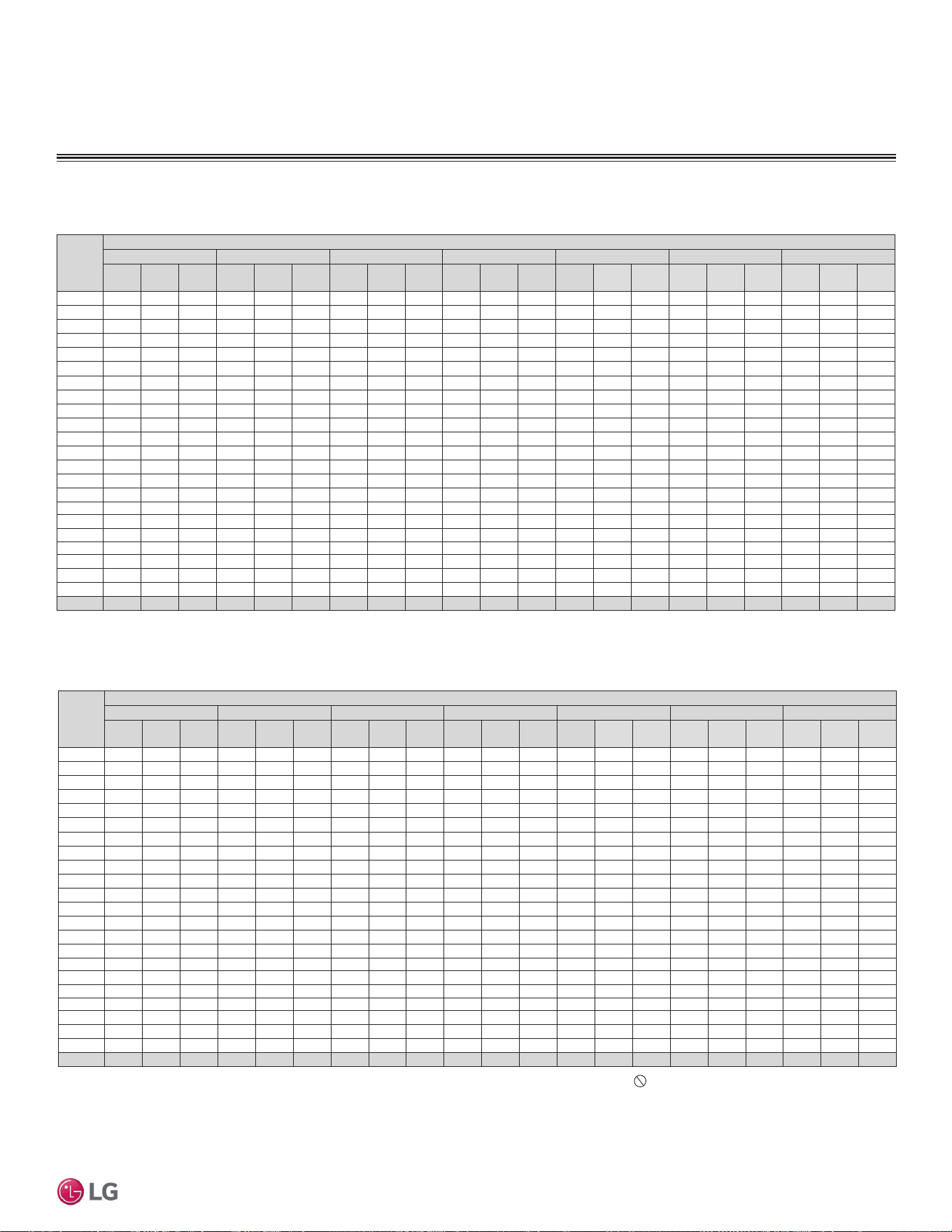
'XHWRRXUSROLF\RIFRQWLQXRXVSURGXFWLQQRYDWLRQVRPHVSHFL¿FDWLRQVPD\FKDQJHZLWKRXWQRWL¿FDWLRQ
©
/*(OHFWURQLFV86$,QF(QJOHZRRG&OLIIV1-$OOULJKWVUHVHUYHG³/*´LVDUHJLVWHUHGWUDGHPDUNRI/*&RUS
PERFORMANCE DATA | 51
Performance Data
PERFORMANCE DATA
&RROLQJ&DSDFLW\
Table 17: LSN0180HEV2 / LSU180HEV2 Cooling Capacities.
Outdoor
Air
Temp.
(°F DB)
Indoor Air Temperature (°F DB/ °F WB)
64 / 53 68 / 57 72 / 61 77 / 64 80 / 67 86 / 72 90 / 75
TC SHC PI TC SHC PI TC SHC PI TC SHC PI TC SHC PI TC SHC PI TC SHC PI
14 11.02 8.76 0.64 13.78 9.32 0.76 16.54 9.89 0.87 19.99 10.60 1.02 22.06 11.03 1.11 18.41 12.03 0.90 15.97 12.69 0.77
23 11.83 9.40 0.63 14.23 10.01 0.76 16.63 10.62 0.89 19.64 11.38 1.06 21.44 11.84 1.16 18.86 12.91 0.92 17.15 13.63 0.77
25 12.02 9.55 0.65 14.37 10.14 0.78 16.72 10.73 0.91 19.65 11.47 1.07 21.42 11.91 1.16 19.07 13.05 0.94 17.51 13.81 0.79
30 12.48 9.92 0.70 14.70 10.47 0.82 16.92 11.01 0.93 19.70 11.69 1.08 21.37 12.10 1.17 19.59 13.40 0.98 18.41 14.26 0.85
35 12.95 10.29 0.74 15.04 10.79 0.85 17.13 11.29 0.96 19.75 11.92 1.10 21.31 12.29 1.18 20.11 13.74 1.01 19.31 14.71 0.90
40 13.41 10.66 0.79 15.37 11.12 0.89 17.34 11.57 0.99 19.79 12.14 1.12 21.26 12.49 1.19 20.63 14.09 1.05 20.21 15.16 0.96
45 13.87 11.03 0.84 15.71 11.44 0.93 17.54 11.85 1.02 19.84 12.37 1.13 21.21 12.68 1.20 21.15 14.44 1.09 21.10 15.61 1.02
50 14.34 11.40 0.89 16.04 11.76 0.97 17.75 12.13 1.05 19.88 12.59 1.15 21.16 12.87 1.21 21.67 14.79 1.13 22.00 16.06 1.07
55 14.80 11.77 0.93 16.38 12.09 1.00 17.96 12.41 1.08 19.93 12.82 1.16 21.11 13.06 1.22 22.19 15.13 1.16 22.90 16.51 1.13
60 15.27 12.13 0.98 16.72 12.41 1.04 18.16 12.69 1.10 19.97 13.04 1.18 21.06 13.25 1.23 22.70 15.48 1.20 23.80 16.97 1.18
65 15.13 12.02 1.03 16.50 12.36 1.09 17.88 12.70 1.15 19.59 13.12 1.22 20.62 13.38 1.27 22.27 15.49 1.25 23.36 16.90 1.25
70 14.99 11.92 1.08 16.29 12.31 1.14 17.59 12.71 1.19 19.21 13.21 1.26 20.19 13.51 1.31 21.83 15.50 1.31 22.92 16.82 1.31
75 14.85 11.81 1.13 16.07 12.26 1.18 17.30 12.72 1.24 18.83 13.29 1.30 19.75 13.63 1.34 21.39 15.51 1.36 22.48 16.75 1.37
80 14.71 11.70 1.18 15.86 12.21 1.23 17.01 12.73 1.28 18.45 13.37 1.34 19.31 13.76 1.38 20.95 15.52 1.41 22.04 16.68 1.43
85 14.57 11.59 1.23 15.65 12.16 1.28 16.72 12.74 1.33 18.07 13.46 1.39 18.87 13.89 1.42 20.51 15.52 1.46 21.60 16.61 1.49
90 14.43 11.48 1.28 15.43 12.11 1.32 16.43 12.75 1.37 17.69 13.54 1.43 18.44 14.02 1.46 20.07 15.53 1.51 21.16 16.54 1.55
95 14.29 11.37 1.33 15.22 12.06 1.37 16.15 12.76 1.41 17.31 13.62 1.47 18.00 14.15
1.50 19.63 15.54 1.57 20.72 16.47 1.61
100 13.92 11.07 1.35 14.87 11.80 1.39 15.82 12.52 1.44 17.01 13.43 1.49 17.72 13.98 1.52 19.30 15.29 1.59 20.35 16.17 1.63
105 13.55 10.77 1.37 14.52 11.53 1.41 15.49 12.29 1.46 16.71 13.24 1.51 17.44 13.81 1.55 18.96 15.05 1.61 19.97 15.87 1.66
110 13.17 10.47 1.39 14.17 11.26 1.43 15.17 12.05 1.48 16.41 13.04 1.53 17.16 13.64 1.57 18.62 14.80 1.63 19.60 15.58 1.68
115 12.70 10.10 1.41 13.67 10.87 1.45 14.63 11.64 1.49 15.84 12.60 1.55 16.56 13.18 1.58 17.99 14.30 1.65 18.94 15.05 1.70
118 12.42 9.87 1.41 13.37 10.63 1.46 14.31 11.39 1.50 15.49 12.33 1.56 16.20 12.90 1.59 17.60 14.00 1.67 18.54 14.74 1.71
122 12.05 10.07 1.43 12.96 10.84 1.47 13.88 11.61 1.52 15.03 12.58 1.58 15.71 13.16 1.61 17.08 14.28 1.68 17.98 15.03 1.73
Table 18: LSN240HEV2 / LSU240HEV2 Cooling Capacities.
Outdoor
Air
Temp.
(°F DB)
Indoor Air Temperature (°F DB/ °F WB)
64 / 53 68 / 57 72 / 61 77 / 64 80 / 67 86 / 72 90 / 75
TC SHC PI TC SHC PI TC SHC PI TC SHC PI TC SHC PI TC SHC PI TC SHC PI
14 13.47 9.98 0.85 16.84 10.62 1.01 20.22 11.27 1.16 24.43 12.08 1.36 26.96 12.56 1.48 22.50 13.70 1.20 19.52 14.46 1.02
23 14.46 10.71 0.84 17.40 11.41 1.02 20.33 12.10 1.19 24.00 12.97 1.41 26.20 13.48 1.55 23.06 14.71 1.23 20.96 15.53 1.02
25 14.69 10.88 0.87 17.56 11.55 1.04 20.43 12.23 1.21 24.02 13.07 1.42 26.18 13.57 1.55 23.31 14.87 1.25 21.40 15.73 1.05
30 15.25 11.30 0.93 17.97 11.92 1.09 20.68 12.55 1.25 24.08 13.32 1.44 26.11 13.79 1.56 23.94 15.26 1.30 22.50 16.25 1.13
35 15.82 11.72 0.99 18.38 12.29 1.14 20.94 12.86 1.28 24.13 13.58 1.47 26.05 14.01 1.57 24.58 15.66 1.35 23.60 16.76 1.20
40 16.39 12.14 1.05 18.79 12.66 1.19 21.19 13.18 1.32 24.19 13.83 1.49 25.99 14.22 1.59 25.21 16.05 1.40 24.70 17.27 1.28
45 16.96 12.56 1.12 19.20 13.03 1.24 21.44 13.50 1.36 24.24 14.09 1.51 25.93 14.44 1.60 25.85 16.45 1.45 25.79 17.79 1.35
50 17.52 12.98 1.18 19.61 13.40 1.29 21.69 13.82 1.40 24.30 14.35 1.53 25.86 14.66 1.61 26.48 16.85 1.50 26.89 18.30 1.43
55 18.09 13.40 1.24 20.02 13.77 1.34 21.95 14.14 1.43 24.36 14.60 1.55 25.80 14.88 1.62 27.12 17.24 1.55 27.99 18.82 1.50
60 18.66 13.83 1.31 20.43 14.14 1.39 22.20 14.46 1.47 24.41 14.86 1.57 25.74 15.10 1.64 27.75 17.64 1.60 29.09 19.33 1.58
65 18.49 13.70 1.37 20.17 14.09 1.45 21.85 14.47 1.53 23.95 14.95 1.63 25.21 15.24 1.69 27.21 17.65 1.67 28.55 19.25 1.66
70 18.32 13.58 1.44 19.91 14.03 1.52 21.50 14.48 1.59 23.48 15.05 1.68 24.67 15.39 1.74 26.68 17.66 1.74 28.02 19.17 1.74
75 18.15 13.45 1.51 19.65 13.97 1.58 21.14 14.49 1.65 23.01 15.14 1.74 24.14 15.53 1.79 26.14 17.67 1.81 27.48 19.09 1.82
80 17.98 13.33 1.57 19.39 13.91 1.64 20.79 14.50 1.71 22.55 15.24 1.79 23.60 15.68 1.84 25.61 17.68 1.88 26.94 19.01 1.90
85 17.81 13.20 1.64 19.12 13.86 1.70 20.44 14.51 1.77 22.08 15.33 1.85 23.07 15.83 1.90 25.07 17.69 1.95 26.40 18.93 1.99
90 17.64 13.08 1.71 18.86 13.80 1.77 20.09 14.52 1.83 21.62 15.43 1.90 22.53 15.97 1.95 24.53 17.70 2.02 25.87 18.85 2.07
95 17.47 12.95 1.77 18.60 13.74 1.83 19.74 14.53 1.89 21.15 15.52 1.96 22.00 16.12
2.00 24.00 17.71 2.09 25.33 18.77 2.15
100 17.01 12.61 1.80 18.17 13.44 1.86 19.34 14.27 1.91 20.79 15.30 1.99 21.66 15.92 2.03 23.58 17.43 2.12 24.87 18.43 2.18
105 16.56 12.27 1.83 17.75 13.13 1.88 18.94 14.00 1.94 20.42 15.08 2.02 21.31 15.73 2.06 23.17 17.14 2.15 24.41 18.09 2.21
110 16.10 11.93 1.85 17.32 12.83 1.91 18.54 13.73 1.97 20.06 14.86 2.05 20.97 15.54 2.09 22.76 16.86 2.18 23.95 17.75 2.24
115 15.53 11.50 1.87 16.70 12.38 1.93 17.88 13.26 1.99 19.35 14.36 2.07 20.24 15.01 2.11 21.98 16.29 2.21 23.14 17.15 2.27
118 15.18 11.25 1.89 16.34 12.11 1.95 17.49 12.97 2.01 18.93 14.05 2.08 19.80 14.70 2.13 21.52 15.95 2.22 22.66 16.79 2.28
122 14.72 11.47 1.91 15.84 12.35 1.97 16.97 13.23 2.03 18.37 14.33 2.10 19.21 14.99 2.15 20.87 16.27 2.24 21.98 17.12 2.31
DB: Dry Bulb Temperature (°F) WB: Wet Bulb Temperature (°F) TC: Total Capacity (kBtu/h)
SHC: Sensible Capacity (kBtu/h) PI: Power Input (kW) (includes compressor,indoor fan motor and
outdoor fan motor)
1. All capacities are net, evaporator fan motor heat is deducted.
2. Grey shading indicates reference data. When operating the unit at this temperature, these values
can be different by discontinuous operation.
3. Direct interpolation is permissible.
Do not extrapolate.
Nominal capacity as rated: 0 ft. above sea level with 24.6 ft. of refrigerant piping.
0 ft. level difference between outdoor and indoor units.
Nominal cooling capacity rating obtained with air entering the indoor unit at 80ºF dry bulb (DB) and
67ºF wet bulb (WB), and outdoor ambient conditions of 95ºF dry bulb (DB) and 75ºF wet bulb (WB).
LS180HEV2, LS240HEV2
Cooling Capacity Table for LS180HEV2 (LSU180HEV2 + LSN180HEV2)
Cooling Capacity Table for LS180HEV2 (LSU180HEV2 + LSN180HEV2)
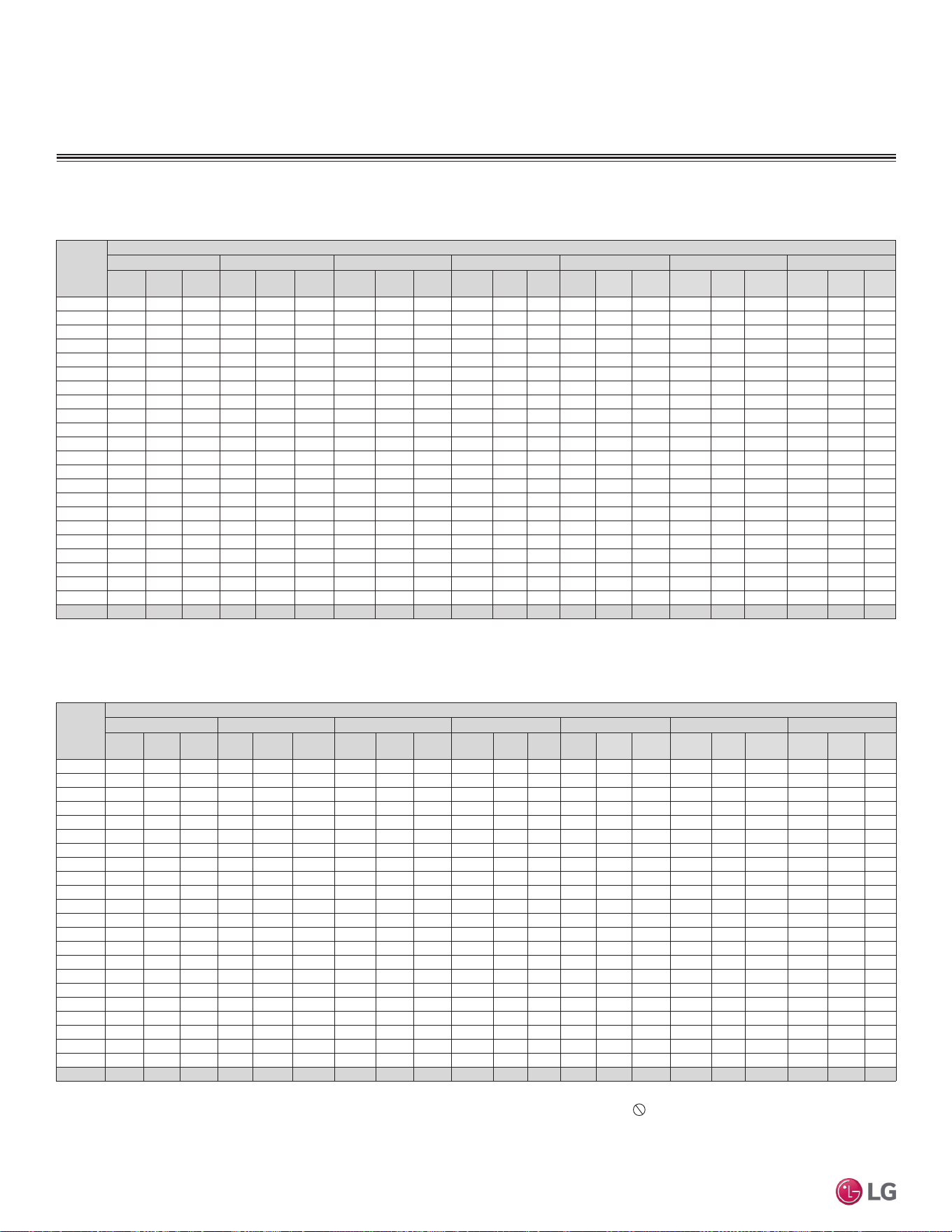
'XHWRRXUSROLF\RIFRQWLQXRXVSURGXFWLQQRYDWLRQVRPHVSHFL¿FDWLRQVPD\FKDQJHZLWKRXWQRWL¿FDWLRQ
©
/*(OHFWURQLFV86$,QF(QJOHZRRG&OLIIV1-$OOULJKWVUHVHUYHG³/*´LVDUHJLVWHUHGWUDGHPDUNRI/*&RUS
52 | PERFORMANCE DATA
Single Zone Mega Wall Mounted Engineering Manual
PERFORMANCE DATA
&RROLQJ&DSDFLW\
Outdoor
Air
Temp.
(°F DB)
Indoor Air Temperature (°F DB/ °F WB)
64 / 53 68 / 57 72 / 61 77 / 64 80 / 67 86 / 72 90 / 75
TC SHC PI TC SHC PI TC SHC PI TC SHC PI TC SHC PI TC SHC PI TC SHC PI
14 7.35 5.66 0.49 7.90 6.08 0.50 8.45 6.50 0.52 9.00 6.93 0.53 9.25 7.12 0.55 10.10 7.77 0.57 10.65 8.20 0.59
23 7.89 6.07 0.48 8.48 6.53 0.50 9.07 6.98 0.51 9.66 7.44 0.53 9.93 7.65 0.55 10.84 8.35 0.57 11.43 8.80 0.58
25 8.00 6.16 0.49 8.59 6.61 0.51 9.18 7.07 0.52 9.77 7.52 0.54 10.04 7.73 0.56 10.95 8.43 0.58 11.54 8.89 0.59
30 8.31 6.40 0.53 8.92 6.86 0.55 9.52 7.33 0.56 10.10 7.78 0.58 10.38 7.99 0.60 11.30 8.70 0.62 11.93 9.18 0.64
35 8.62 6.64 0.57 9.24 7.12 0.58 9.86 7.59 0.60 10.43 8.03 0.62 10.72 8.25 0.64 11.64 8.96 0.66 12.31 9.48 0.68
40 8.93 6.88 0.60 9.57 7.37 0.62 10.20 7.85 0.64 10.75 8.28 0.66 11.05 8.51 0.68 11.98 9.23 0.71 12.70 9.78 0.73
45 9.24 7.12 0.64 9.89 7.62 0.66 10.54 8.12 0.68 11.08 8.53 0.70 11.39 8.77 0.72 12.32 9.49 0.75 13.08 10.07 0.77
50 9.56 7.36 0.67 10.22 7.87 0.70 10.88 8.38 0.72 11.41 8.79 0.74 11.73 9.03 0.76 12.67 9.75 0.79 13.46 10.37 0.82
55 9.87 7.60 0.71 10.54 8.12 0.73 11.22 8.64 0.76 11.74 9.04 0.78 12.07 9.29 0.80 13.01 10.02 0.83 13.85 10.66 0.86
60 10.18 7.84 0.75 10.87 8.37 0.77 11.56 8.90 0.79 12.06 9.29 0.82 12.40 9.55 0.84 13.35 10.28 0.88 14.23 10.96 0.90
65 10.49 8.08 0.78 11.19 8.62 0.81 11.90 9.16 0.83 12.39 9.54 0.86 12.74 9.81 0.89 13.70 10.55 0.92 14.62 11.25 0.95
70 10.80 8.32 0.82 11.52 8.87 0.85 12.24 9.42 0.87 12.72 9.79 0.90 13.08 10.07 0.93 14.04 10.81 0.96 15.00 11.55 0.99
75 10.66 8.21 0.84 11.38 8.77 0.87 12.11 9.32 0.90 12.60 9.70 0.92 12.96 9.98 0.95 13.86 10.67 0.99 14.88 11.46 1.02
80 10.38 7.99 0.88 11.10 8.55 0.91 11.82 9.10 0.94 12.36 9.52 0.96 12.84 9.89 0.99 13.68 10.53 1.03 14.64 11.27 1.07
85 10.11 7.78 0.94 10.83 8.34 0.97 11.54 8.89 1.00 12.12 9.33 1.03 12.60 9.70 1.06 13.50 10.40 1.11 14.42 11.10 1.14
90 9.83 7.57 0.98 10.55 8.12 1.01 11.26 8.67 1.04 11.88 9.15 1.08 12.36 9.52 1.11 13.32 10.26 1.15 14.13 10.88 1.19
95 9.53 7.34 1.01 10.25 7.89 1.04 10.96 8.44 1.08 11.67 8.99 1.11 12.00 9.24
1.14 13.10 10.09 1.19 13.81 10.64 1.22
100 9.28 7.15 1.03 10.00 7.70 1.06 10.71 8.25 1.09 11.42 8.80 1.13 11.84 9.12 1.16 12.85 9.89 1.21 13.56 10.44 1.24
105 9.03 6.95 1.05 9.75 7.50 1.08 10.46 8.05 1.11 11.17 8.60 1.15 11.69 9.00 1.18 12.60 9.70 1.23 13.31 10.25 1.27
110 8.78 6.76 1.06 9.50 7.31 1.09 10.21 7.86 1.12 10.92 8.41 1.16 11.44 8.81 1.19 12.35 9.51 1.24 13.07 10.06 1.28
115 8.53 6.57 1.07 9.25 7.12 1.10 9.96 7.67 1.13 10.67 8.22 1.17 11.19 8.62 1.21 12.10 9.32 1.25 12.82 9.87 1.29
118 8.28 6.38 1.08 9.00 6.93 1.11 9.60 7.39 1.15 10.32 7.95 1.18 10.80 8.32 1.22 11.70 9.01 1.27 12.36 9.52 1.30
122 7.89 6.07 1.08 8.56 6.59 1.12 9.24 7.11 1.15 9.91 7.63 1.19 10.40 8.01 1.22 11.27 8.67 1.27 11.94 9.19 1.31
Outdoor
Air
Temp.
(°F DB)
Indoor Air Temperature (°F DB/ °F WB)
64 / 53 68 / 57 72 / 61 77 / 64 80 / 67 86 / 72 90 / 75
TC SHC PI TC SHC PI TC SHC PI TC SHC PI TC SHC PI TC SHC PI TC SHC PI
14 5.20 4.58 0.30 5.59 4.92 0.31 5.98 5.26 0.32 6.37 5.61 0.33 6.55 5.77 0.34 7.15 6.29 0.35 7.54 6.64 0.36
23 5.59 4.92 0.30 6.00 5.28 0.31 6.42 5.65 0.32 6.84 6.02 0.33 7.03 6.19 0.34 7.68 6.76 0.35 8.10 7.13 0.36
25 5.67 4.99 0.31 6.08 5.35 0.31 6.50 5.72 0.32 6.92 6.09 0.33 7.11 6.26 0.34 7.76 6.83 0.36 8.18 7.19 0.37
30 5.89 5.18 0.33 6.31 5.56 0.34 6.74 5.93 0.35 7.15 6.29 0.36 7.35 6.47 0.37 8.00 7.04 0.38 8.45 7.43 0.40
35 6.11 5.37 0.35 6.55 5.76 0.36 6.98 6.15 0.37 7.39 6.50 0.38 7.59 6.68 0.40 8.24 7.25 0.41 8.72 7.67 0.42
40 6.33 5.57 0.37 6.78 5.96 0.38 7.23 6.36 0.40 7.62 6.70 0.41 7.83 6.89 0.42 8.49 7.47 0.44 8.99 7.91 0.45
45 6.55 5.76 0.40 7.01 6.17 0.41 7.47 6.57 0.42 7.85 6.91 0.43 8.07 7.10 0.45 8.73 7.68 0.46 9.26 8.15 0.48
50 6.77 5.96 0.42 7.24 6.37 0.43 7.71 6.78 0.44 8.08 7.11 0.46 8.31 7.31 0.47 8.97 7.90 0.49 9.54 8.39 0.51
55 6.99 6.15 0.44 7.47 6.57 0.45 7.95 6.99 0.47 8.31 7.32 0.48 8.55 7.52 0.50 9.22 8.11 0.52 9.81 8.63 0.53
60 7.21 6.34 0.46 7.70 6.77 0.48 8.19 7.21 0.49 8.55 7.52 0.51 8.79 7.73 0.52 9.46 8.32 0.54 10.08 8.87 0.56
65 7.43 6.54 0.49 7.93 6.98 0.50 8.43 7.42 0.52 8.78 7.72 0.53 9.03 7.94 0.55 9.70 8.54 0.57 10.35 9.11 0.59
70 7.65 6.73 0.51 8.16 7.18 0.52 8.67 7.63 0.54 9.01 7.93 0.56 9.27 8.15 0.57 9.95 8.75 0.60 10.63 9.35 0.61
75 7.55 6.65 0.52 8.06 7.10 0.54 8.58 7.55 0.56 8.93 7.85 0.57 9.18 8.08 0.59 9.82 8.64 0.61 10.54 9.28 0.63
80 7.35 6.47 0.55 7.86 6.92 0.56 8.38 7.37 0.58 8.76 7.70 0.60 9.10 8.00 0.62 9.69 8.53 0.64 10.37 9.13 0.66
85 7.16 6.30 0.58 7.67 6.75 0.60 8.18 7.20 0.62 8.59 7.55 0.64 8.93 7.85 0.66 9.56 8.42 0.68 10.21 8.99 0.71
90 6.96 6.13 0.61 7.47 6.57 0.63 7.98 7.02 0.65 8.42 7.41 0.67 8.76 7.70 0.69 9.44 8.30 0.71 10.01 8.81 0.74
95 6.75 5.94 0.63 7.26 6.39 0.65 7.76 6.83 0.67 8.27 7.28 0.69 8.50 7.48
0.71 9.28 8.17 0.74 9.78 8.61 0.76
100 6.57 5.79 0.64 7.08 6.23 0.66 7.59 6.68 0.68 8.09 7.12 0.70 8.39 7.38 0.72 9.10 8.01 0.75 9.61 8.46 0.77
105 6.40 5.63 0.65 6.90 6.08 0.67 7.41 6.52 0.69 7.91 6.96 0.71 8.28 7.29 0.73 8.93 7.85 0.76 9.43 8.30 0.78
110 6.22 5.47 0.65 6.73 5.92 0.68 7.23 6.36 0.70 7.74 6.81 0.72 8.10 7.13 0.74 8.75 7.70 0.77 9.25 8.14 0.79
115 6.04 5.32 0.66 6.55 5.76 0.68 7.06 6.21 0.70 7.56 6.65 0.72 7.93 6.98 0.75 8.57 7.54 0.78 9.08 7.99 0.80
118 5.87 5.16 0.67 6.38 5.61 0.69 6.80 5.98 0.71 7.31 6.43 0.73 7.65 6.73 0.75 8.29 7.29 0.78 8.76 7.70 0.81
122 5.59 4.92 0.67 6.07 5.34 0.69 6.54 5.76 0.71 7.02 6.18 0.73 7.37 6.48 0.76 7.98 7.02 0.79 8.46 7.44 0.81
Table 19: LSN090HXV / LSU090HXV Cooling Capacities.
Table 20: LSN120HXV / LSU120HXV Cooling Capacities.
LS090HXV, LS120HXV
DB: Dry Bulb Temperature (°F) WB: Wet Bulb Temperature (°F) TC: Total Capacity (kBtu/h)
SHC: Sensible Capacity (kBtu/h) PI: Power Input (kW) (includes compressor,indoor fan motor and
outdoor fan motor)
1. All capacities are net, evaporator fan motor heat is deducted.
2. Grey shading indicates reference data. When operating the unit at this temperature, these values
can be different by discontinuous operation.
3. Direct interpolation is permissible.
Do not extrapolate.
Nominal capacity as rated: 0 ft. above sea level with 24.6 ft. of refrigerant piping.
0 ft. level difference between outdoor and indoor units.
Nominal cooling capacity rating obtained with air entering the indoor unit at 80ºF dry bulb (DB) and
67ºF wet bulb (WB), and outdoor ambient conditions of 95ºF dry bulb (DB) and 75ºF wet bulb (WB).
Cooling Capacity Table for LS090HXV (LSU090HXV + LSN090HXV)
Cooling Capacity Table for LS120HXV (LSU120HXV + LSN120HXV)
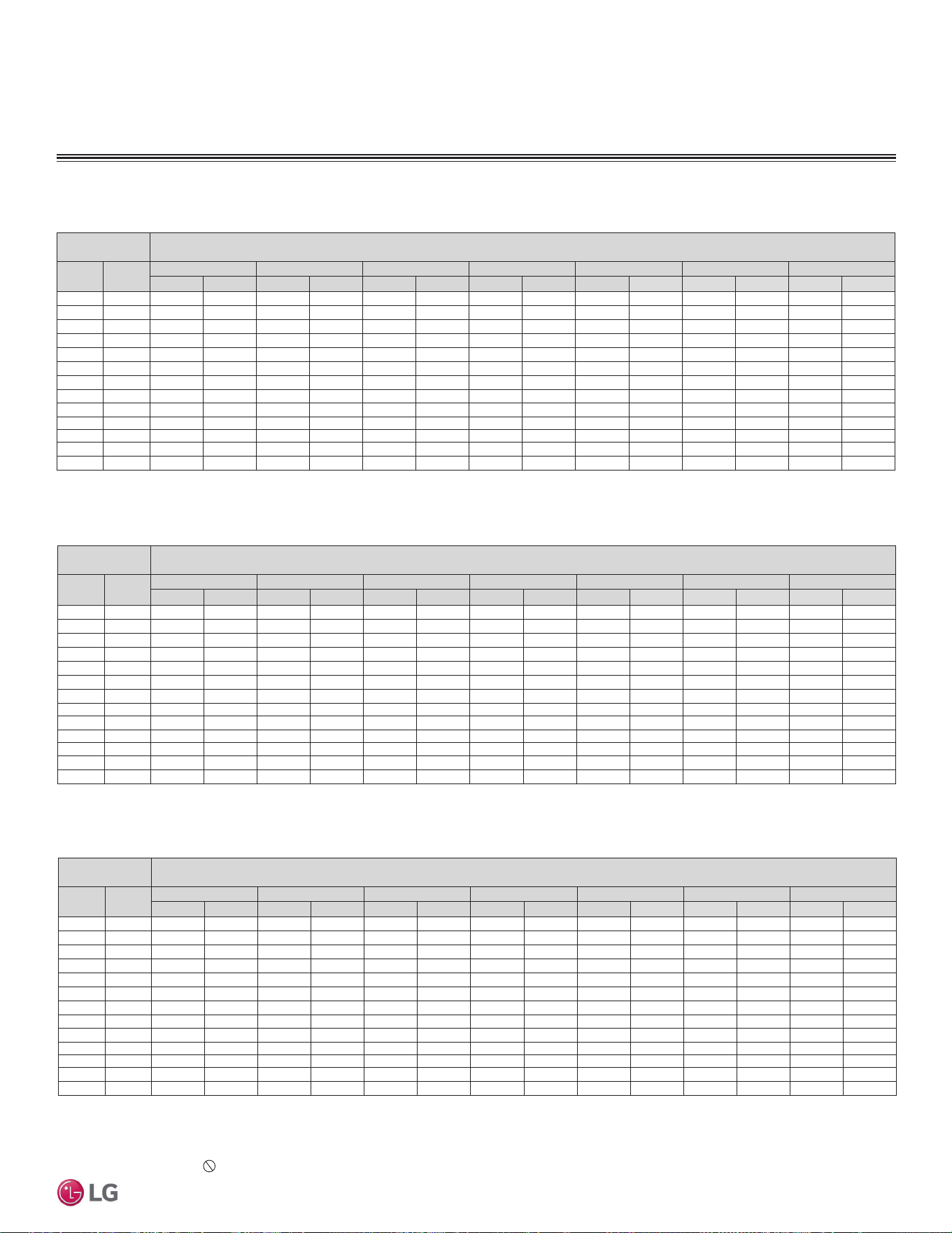
'XHWRRXUSROLF\RIFRQWLQXRXVSURGXFWLQQRYDWLRQVRPHVSHFL¿FDWLRQVPD\FKDQJHZLWKRXWQRWL¿FDWLRQ
©
/*(OHFWURQLFV86$,QF(QJOHZRRG&OLIIV1-$OOULJKWVUHVHUYHG³/*´LVDUHJLVWHUHGWUDGHPDUNRI/*&RUS
PERFORMANCE DATA | 53
Performance Data
+HDWLQJ&DSDFLW\
PERFORMANCE DATA
DB: Dry Bulb Temperature (°F) WB: Wet Bulb Temperature (°F) TC: Total Capacity (kBtu/h)
PI: Power Input (kW) (includes compressor,indoor fan motor and outdoor fan motor)
1. All capacities are net, evaporator fan motor heat is deducted.
2. Direct interpolation is permissible.
Do not extrapolate.
Nominal capacity as rated: 0 ft. above sea level with 24.6 ft. of refrigerant piping.
0 ft. level difference between outdoor and indoor units.
Nominal heating capacity rating obtained with air entering the indoor unit at 70ºF dry bulb (DB) and
60ºF wet bulb (WB), and outdoor ambient conditions of 47ºF dry bulb (DB) and 43ºF wet bulb (WB).
Outdoor Air
Temp.
Indoor Air Temperature (°F DB)
°F DB °F WB
60 64 68 70 72 75 86
TC PI TC PI TC PI TC PI TC PI TC PI TC PI
16 14 6.90 0.70 6.69 0.69 6.62 0.69 6.55 0.68 6.50 0.68 6.37 0.68 6.22 0.68
17 15 6.94 0.71 6.73 0.70 6.67 0.70 6.60 0.69 6.55 0.69 6.42 0.68 6.26 0.68
19 17 7.04 0.72 6.82 0.71 6.76 0.71 6.69 0.71 6.64 0.71 6.50 0.70 6.35 0.70
24 23 7.72 0.75 7.49 0.74 7.41 0.74 7.34 0.73 7.28 0.73 7.13 0.72 6.96 0.72
32 30 9.25 0.81 8.97 0.80 8.88 0.80 8.79 0.79 8.73 0.79 8.55 0.78 8.35 0.78
41 38 10.62 0.86 10.30 0.85 10.19 0.85 10.09 0.84 10.01 0.84 9.81 0.83 9.58 0.83
43 40 10.96 0.87 10.63 0.86 10.52 0.86 10.41 0.86 10.33 0.86 10.13 0.85 9.89 0.85
47 43 11.47 0.89 11.12 0.88 11.01 0.88 10.90 0.88 10.82 0.88 10.60 0.87 10.35 0.87
53 50 11.58 0.90 11.23 0.89 11.12 0.89 11.01 0.88 10.92 0.88 10.71 0.87 10.45 0.87
59 53 11.85 0.91 11.49 0.90 11.37 0.90 11.26 0.89 11.17 0.89 10.95 0.88 10.69 0.88
64 57 12.10 0.93 11.73 0.92 11.61 0.92 11.50 0.91 11.41 0.91 11.18 0.90 10.92 0.90
70 61 12.33 0.94 11.96 0.93 11.83 0.93 11.72 0.92 11.63 0.92 11.39 0.91 11.12 0.91
75 65 12.50 0.95 12.12 0.95 12.00 0.95 11.88 0.94 11.79 0.94 11.55 0.93 11.28 0.93
Table 21: LSN090HEV2 / LSU090HEV2 Heating Capacities.
Outdoor Air
Temp.
Indoor Air Temperature (°F DB)
°F DB °F WB
60 64 68 70 72 75 86
TC PI TC PI TC PI TC PI TC PI TC PI TC PI
16 14 7.59 0.80 7.36 0.79 7.29 0.79 7.22 0.78 7.16 0.78 7.02 0.77 6.85 0.77
17 15 7.65 0.81 7.41 0.80 7.34 0.80 7.27 0.79 7.21 0.79 7.07 0.78 6.90 0.78
19 17 7.75 0.82 7.51 0.81 7.44 0.81 7.36 0.81 7.31 0.81 7.16 0.80 6.99 0.80
24 23 8.50 0.85 8.24 0.84 8.16 0.84 8.08 0.84 8.02 0.84 7.85 0.83 7.67 0.83
32 30 10.19 0.92 9.88 0.91 9.78 0.91 9.68 0.90 9.61 0.90 9.41 0.89 9.19 0.89
41 38 11.69 0.98 11.33 0.97 11.22 0.97 11.11 0.96 11.02 0.96 10.80 0.95 10.55 0.95
43 40 12.06 1.00 11.70 0.99 11.58 0.99 11.47 0.98 11.38 0.98 11.15 0.97 10.88 0.97
47 43 12.63 1.02 12.24 1.01 12.12 1.01 12.00 1.00 11.91 1.00 11.67 0.99 11.39 0.99
53 50 12.75 1.03 12.37 1.02 12.24 1.02 12.12 1.01 12.03 1.01 11.79 1.00 11.51 1.00
59 53 13.04 1.04 12.65 1.03 12.52 1.03 12.40 1.02 12.30 1.02 12.05 1.01 11.77 1.01
64 57 13.32 1.06 12.92 1.05 12.79 1.05 12.66 1.04 12.56 1.04 12.31 1.03 12.02 1.03
70 61 13.57 1.08 13.16 1.07 13.03 1.07 12.90 1.06 12.80 1.06 12.54 1.04 12.25 1.04
75 65 13.76 1.09 13.35 1.08 13.21 1.08 13.08 1.07 12.98 1.07 12.72 1.06 12.42 1.06
Table 22: LSN120HEV2 / LSU120HEV2 Heating Capacities.
Outdoor Air
Temp.
Indoor Air Temperature (°F DB)
°F DB °F WB
60 64 68 70 72 75 86
TC PI TC PI TC PI TC PI TC PI TC PI TC PI
16 14 12.02 1.26 11.66 1.25 11.54 1.25 11.43 1.24 11.34 1.24 11.11 1.23 10.85 1.23
17 15 12.10 1.28 11.74 1.26 11.62 1.26 11.50 1.25 11.42 1.25 11.19 1.24 10.92 1.24
19 17 12.27 1.30 11.90 1.29 11.78 1.29 11.66 1.28 11.57 1.28 11.34 1.26 11.07 1.26
24 23 13.46 1.35 13.05 1.34 12.92 1.34 12.79 1.32 12.69 1.32 12.44 1.31 12.14 1.31
32 30 16.13 1.46 15.64 1.44 15.48 1.44 15.33 1.43 15.21 1.43 14.91 1.42 14.55 1.42
41 38 18.51 1.55 17.95 1.54 17.76 1.54 17.59 1.52 17.45 1.52 17.10 1.51 16.70 1.51
43 40 19.10 1.58 18.52 1.56 18.33 1.56 18.15 1.55 18.01 1.55 17.65 1.53 17.23 1.53
47 43 19.99 1.61 19.39 1.60 19.19 1.60 19.00 1.58 18.85 1.58 18.48 1.57 18.04 1.57
53 50 20.19 1.63 19.58 1.61 19.38 1.61 19.19 1.60 19.04 1.60 18.66 1.58 18.22 1.58
59 53 20.65 1.65 20.03 1.63 19.82 1.63 19.63 1.61 19.48 1.61 19.09 1.60 18.63 1.60
64 57 21.09 1.68 20.45 1.66 20.25 1.66 20.05 1.65 19.89 1.65 19.49 1.63 19.03 1.63
70 61 21.49 1.70 20.84 1.69 20.63 1.69 20.43 1.67 20.27 1.67 19.86 1.65 19.39 1.65
75 65 21.79 1.73 21.13 1.71 20.92 1.71 20.71 1.69 20.55 1.69 20.14 1.68 19.66 1.68
Table 23: LSN180HEV2 / LSU180HEV2 Heating Capacities.
LS090HEV2, LS120HEV2, LS180HEV2
Heating Capacity Table for LS090HEV2 (LSU090HEV2 + LSN090HEV2)
Heating Capacity Table for LS120HEV2 (LSU120HEV2 + LSN120HEV2)
Heating Capacity Table for LS180HEV2 (LSU180HEV2 + LSN180HEV2)
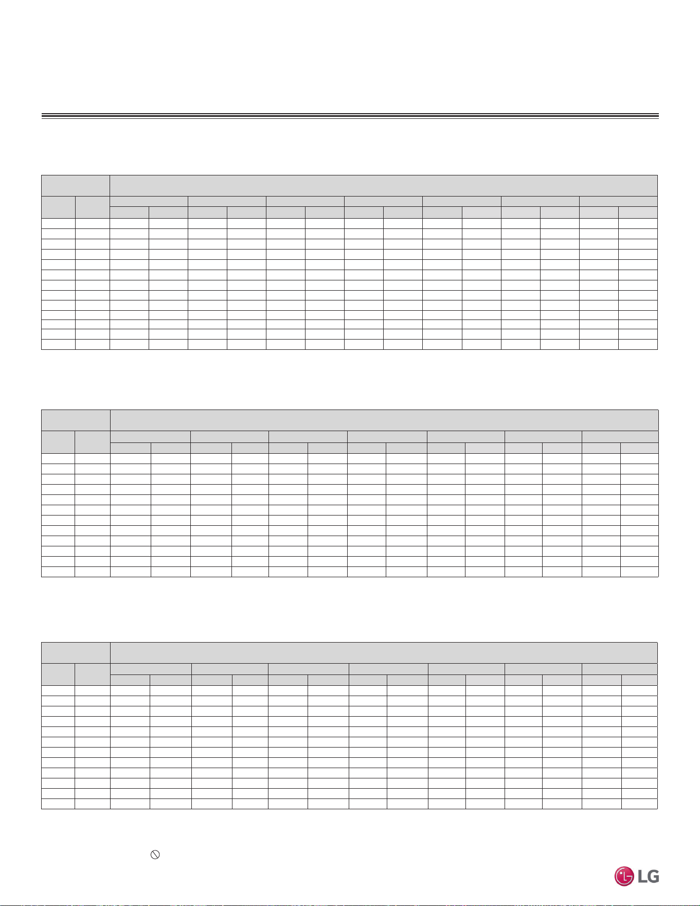
'XHWRRXUSROLF\RIFRQWLQXRXVSURGXFWLQQRYDWLRQVRPHVSHFL¿FDWLRQVPD\FKDQJHZLWKRXWQRWL¿FDWLRQ
©
/*(OHFWURQLFV86$,QF(QJOHZRRG&OLIIV1-$OOULJKWVUHVHUYHG³/*´LVDUHJLVWHUHGWUDGHPDUNRI/*&RUS
54 | PERFORMANCE DATA
Single Zone Mega Wall Mounted Engineering Manual
+HDWLQJ&DSDFLW\
PERFORMANCE DATA
Outdoor Air
Temp.
Indoor Air Temperature (°F DB)
°F DB °F WB
60 64 68 70 72 75 86
TC PI TC PI TC PI TC PI TC PI TC PI TC PI
16 14 6.90 0.70 6.69 0.70 6.62 0.70 6.55 0.69 6.50 0.69 6.37 0.68 6.22 0.68
19 17 7.04 0.72 6.82 0.72 6.76 0.72 6.69 0.71 6.64 0.71 6.50 0.70 6.35 0.70
24 23 7.72 0.75 7.49 0.74 7.41 0.74 7.34 0.74 7.28 0.74 7.13 0.73 6.96 0.73
32 30 9.25 0.81 8.97 0.80 8.88 0.80 8.79 0.80 8.73 0.80 8.55 0.79 8.35 0.79
41 38 10.62 0.86 10.30 0.86 10.19 0.86 10.09 0.85 10.01 0.85 9.81 0.84 9.58 0.84
43 40 10.96 0.88 10.63 0.87 10.52 0.87 10.41 0.86 10.33 0.86 10.13 0.85 9.89 0.85
47 43 11.47 0.90 11.12 0.89 11.01 0.89 10.90 0.88 10.82 0.88 10.60 0.87 10.35 0.87
53 50 11.58 0.91 11.23 0.90 11.12 0.90 11.01 0.89 10.92 0.89 10.71 0.88 10.45 0.88
59 53 11.85 0.92 11.49 0.91 11.37 0.91 11.26 0.90 11.17 0.90 10.95 0.89 10.69 0.89
64 57 12.10 0.93 11.73 0.92 11.61 0.92 11.50 0.92 11.41 0.92 11.18 0.91 10.92 0.91
70 61 12.33 0.95 11.96 0.94 11.83 0.94 11.72 0.93 11.63 0.93 11.39 0.92 11.12 0.92
75 65 12.50 0.96 12.12 0.95 12.00 0.95 11.88 0.94 11.79 0.94 11.55 0.93 11.28 0.93
Outdoor Air
Temp.
Indoor Air Temperature (°F DB)
°F DB °F WB
60 64 68 70 72 75 86
TC PI TC PI TC PI TC PI TC PI TC PI TC PI
16 14 8.23 0.87 7.98 0.86 7.90 0.86 7.82 0.85 7.76 0.85 7.60 0.84 7.42 0.84
19 17 8.39 0.90 8.14 0.89 8.06 0.89 7.98 0.88 7.92 0.88 7.76 0.87 7.57 0.87
24 23 9.21 0.93 8.93 0.92 8.84 0.92 8.75 0.91 8.68 0.91 8.51 0.90 8.31 0.90
32 30 11.04 1.00 10.70 0.99 10.59 0.99 10.49 0.98 10.41 0.98 10.20 0.97 9.96 0.97
41 38 12.66 1.07 12.28 1.06 12.15 1.06 12.03 1.05 11.94 1.05 11.70 1.04 11.42 1.04
43 40 13.07 1.09 12.67 1.07 12.54 1.07 12.42 1.06 12.33 1.06 12.08 1.05 11.79 1.05
47 43 13.68 1.11 13.26 1.10 13.13 1.10 13.00 1.09 12.90 1.09 12.64 1.08 12.34 1.08
53 50 13.82 1.12 13.40 1.11 13.26 1.11 13.13 1.10 13.03 1.10 12.77 1.09 12.46 1.09
59 53 14.13 1.13 13.70 1.12 13.56 1.12 13.43 1.11 13.33 1.11 13.06 1.10 12.75 1.10
64 57 14.43 1.15 13.99 1.14 13.85 1.14 13.72 1.13 13.61 1.13 13.34 1.12 13.02 1.12
70 61 14.71 1.17 14.26 1.16 14.11 1.16 13.98 1.15 13.87 1.15 13.59 1.14 13.27 1.14
75 65 14.91 1.19 14.46 1.18 14.31 1.18 14.17 1.16 14.06 1.16 13.78 1.15 13.45 1.15
LS240HEV2, LS090HXV, LS120HXV
Outdoor Air
Temp.
Indoor Air Temperature (°F DB)
°F DB °F WB
60 64 68 70 72 75 86
TC PI TC PI TC PI TC PI TC PI TC PI TC PI
16 14 13.92 1.54 13.50 1.53 13.36 1.53 13.23 1.51 13.13 1.51 12.87 1.50 12.56 1.50
17 15 14.02 1.56 13.59 1.54 13.45 1.54 13.32 1.53 13.22 1.53 12.95 1.51 12.64 1.51
19 17 14.21 1.59 13.77 1.57 13.64 1.57 13.50 1.56 13.40 1.56 13.13 1.54 12.82 1.54
24 23 15.58 1.65 15.11 1.63 14.96 1.63 14.81 1.61 14.69 1.61 14.40 1.60 14.06 1.60
32 30 18.68 1.78 18.11 1.76 17.93 1.76 17.75 1.74 17.61 1.74 17.26 1.73 16.85 1.73
41 38 21.43 1.90 20.78 1.88 20.57 1.88 20.37 1.86 20.21 1.86 19.80 1.84 19.33 1.84
43 40 22.12 1.92 21.45 1.91 21.23 1.91 21.02 1.89 20.86 1.89 20.44 1.87 19.95 1.87
47 43 23.15 1.97 22.45 1.95 22.22 1.95 22.00 1.93 21.83 1.93 21.39 1.91 20.88 1.91
53 50 23.38 1.99 22.67 1.97 22.44 1.97 22.22 1.95 22.05 1.95 21.61 1.93 21.09 1.93
59 53 23.91 2.01 23.19 1.99 22.95 1.99 22.73 1.97 22.55 1.97 22.10 1.95 21.57 1.95
64 57 24.42 2.05 23.68 2.03 23.44 2.03 23.21 2.01 23.03 2.01 22.57 1.99 22.03 1.99
70 61 24.89 2.08 24.13 2.06 23.89 2.06 23.65 2.04 23.47 2.04 23.00 2.02 22.45 2.02
75 65 25.23 2.11 24.47 2.09 24.22 2.09 23.98 2.07 23.80 2.07 23.32 2.04 22.76 2.04
Table 24: LSN240HEV2 / LSU240HEV2 Heating Capacities.
DB: Dry Bulb Temperature (°F) WB: Wet Bulb Temperature (°F) TC: Total Capacity (kBtu/h)
PI: Power Input (kW) (includes compressor,indoor fan motor and outdoor fan motor)
1. All capacities are net, evaporator fan motor heat is deducted.
2. Direct interpolation is permissible.
Do not extrapolate.
Nominal capacity as rated: 0 ft. above sea level with 24.6 ft. of refrigerant piping.
0 ft. level difference between outdoor and indoor units.
Nominal heating capacity rating obtained with air entering the indoor unit at 70ºF dry bulb (DB) and
60ºF wet bulb (WB), and outdoor ambient conditions of 47ºF dry bulb (DB) and 43ºF wet bulb (WB).
Table 25: LSN090HXV / LSU090HXV Heating Capacities.
Table 26: LSN120HXV / LSU120HXV Heating Capacities.
Heating Capacity Table for LS240HEV2 (LSU240HEV2 + LSN240HEV2)
Heating Capacity Table for LS090HXV (LSU090HXV + LSN090HXV)
Heating Capacity Table for LS120HXV (LSU120HXV + LSN120HXV)
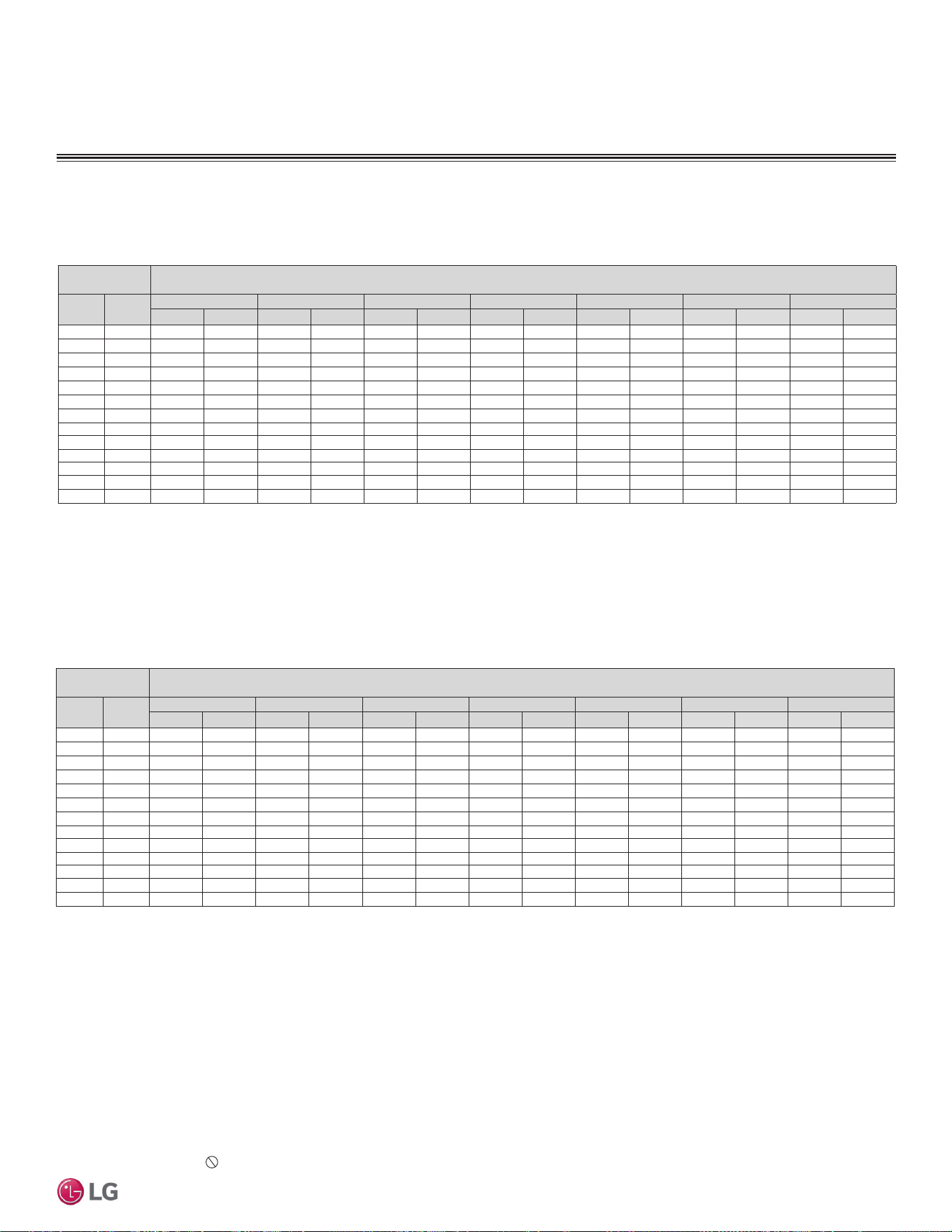
'XHWRRXUSROLF\RIFRQWLQXRXVSURGXFWLQQRYDWLRQVRPHVSHFL¿FDWLRQVPD\FKDQJHZLWKRXWQRWL¿FDWLRQ
©
/*(OHFWURQLFV86$,QF(QJOHZRRG&OLIIV1-$OOULJKWVUHVHUYHG³/*´LVDUHJLVWHUHGWUDGHPDUNRI/*&RUS
PERFORMANCE DATA | 55
Performance Data
0D[LPXP+HDWLQJ&DSDFLW\
PERFORMANCE DATA
Maximum Heating Capacity Table for LS090HEV2 (LSU090HEV2 +
LSN090HEV2)
Maximum Heating Capacity Table for LS120HEV2 (LSU120HEV2 +
LSN120HEV2)
Table 27: LSN090HEV2 / LSU090HEV2 Heating Capacities.
Outdoor Air
Temp.
Indoor Air Temperature (°F DB)
°F DB °F WB
60 64 68 70 72 75 86
TC PI TC PI TC PI TC PI TC PI TC PI TC PI
16 14 8.37 1.15 8.25 1.17 8.13 1.18 8.08 1.19 7.84 1.17 7.51 1.15 6.22 1.06
17 15 8.68 1.16 8.56 1.18 8.44 1.19 8.39 1.20 8.14 1.18 7.80 1.14 6.44 1.01
19 17 9.17 1.16 9.05 1.18 8.92 1.19 8.76 1.20 8.58 1.17 8.19 1.13 6.68 0.99
24 23 10.07 1.17 9.93 1.18 9.80 1.18 9.74 1.18 9.36 1.15 8.83 1.11 6.89 0.95
32 30 10.97 1.13 10.84 1.14 10.70 1.14 10.64 1.14 10.13 1.10 9.43 1.05 6.95 0.86
41 38 11.84 1.05 11.70 1.07 11.55 1.10 11.49 1.11 10.90 1.05 10.09 0.99 7.33 0.73
43 40 12.20 1.01 12.05 1.03 11.91 1.05 11.84 1.06 11.22 1.01 10.37 0.93 7.47 0.67
47 43 12.93 0.97 12.78 1.00 12.63 1.04 12.52 1.05 11.90 0.99 10.99 0.91 7.90 0.63
53 50 12.74 0.94 12.58 0.97 12.42 1.01 12.45 1.02 11.61 0.96 10.61 0.86 7.29 0.53
59 53 12.59 0.92 12.58 0.96 12.57 1.00 12.46 1.02 11.77 0.95 10.68 0.86 7.19 0.54
64 57 12.81 0.90 12.62 0.91 12.42 0.93 12.33 0.94 11.57 0.88 10.53 0.80 7.11 0.52
70 61 12.86 0.85 12.63 0.85 12.40 0.85 12.30 0.85 11.55 0.80 10.52 0.73 7.14 0.47
75 65 13.05 0.77 12.78 0.79 12.51 0.82 12.28 0.83 11.62 0.78 10.58 0.70 7.08 0.43
Table 28: LSN120HEV2 / LSU120HEV2 Heating Capacities.
Outdoor Air
Temp.
Indoor Air Temperature (°F DB)
°F DB °F WB
60 64 68 70 72 75 86
TC PI TC PI TC PI TC PI TC PI TC PI TC PI
16 14 9.21 1.31 9.08 1.33 8.95 1.35 8.89 1.36 8.63 1.34 8.27 1.31 6.85 1.21
17 15 9.56 1.33 9.43 1.35 9.29 1.36 9.23 1.37 8.96 1.34 8.59 1.30 7.09 1.15
19 17 10.10 1.33 9.96 1.35 9.82 1.36 9.64 1.37 9.45 1.34 9.02 1.29 7.35 1.14
24 23 11.08 1.34 10.94 1.34 10.79 1.35 10.73 1.35 10.30 1.31 9.72 1.27 7.58 1.09
32 30 12.08 1.30 11.93 1.30 11.78 1.30 11.71 1.30 11.15 1.26 10.38 1.20 7.65 0.99
41 38 13.03 1.20 12.88 1.23 12.72 1.25 12.65 1.26 12.00 1.21 11.11 1.13 8.07 0.84
43 40 13.43 1.15 13.27 1.17 13.11 1.20 13.04 1.21 12.35 1.15 11.41 1.07 8.22 0.77
47 43 14.23 1.11 14.07 1.14 13.91 1.18 13.78 1.20 13.10 1.14 12.10 1.05 8.70 0.72
53 50 14.03 1.08 13.85 1.11 13.67 1.15 13.71 1.17 12.79 1.09 11.69 0.99 8.02 0.61
59 53 13.86 1.05 13.85 1.10 13.84 1.14 13.71 1.16 12.96 1.09 11.76 0.99 7.91 0.61
64 57 14.11 1.03 13.89 1.04 13.67 1.06 13.58 1.07 12.74 1.01 11.60 0.92 7.83 0.59
70 61 14.16 0.98 13.91 0.97 13.65 0.97 13.54 0.97 12.71 0.91 11.58 0.83 7.87 0.54
75 65 14.36 0.88 14.07 0.91 13.77 0.94 13.52 0.95 12.79 0.89 11.64 0.80 7.80 0.49
DB: Dry Bulb Temperature (°F) WB: Wet Bulb Temperature (°F) TC: Total Capacity (kBtu/h)
PI: Power Input (kW) (includes compressor,indoor fan motor and outdoor fan motor)
1. All capacities are net, evaporator fan motor heat is deducted.
2. Direct interpolation is permissible.
Do not extrapolate.
Nominal capacity as rated: 0 ft. above sea level with 24.6 ft. of refrigerant piping.
0 ft. level difference between outdoor and indoor units.
Nominal heating capacity rating obtained with air entering the indoor unit at 70ºF dry bulb (DB) and
60ºF wet bulb (WB), and outdoor ambient conditions of 47ºF dry bulb (DB) and 43ºF wet bulb (WB).
LS090HEV2, LS120HEV2
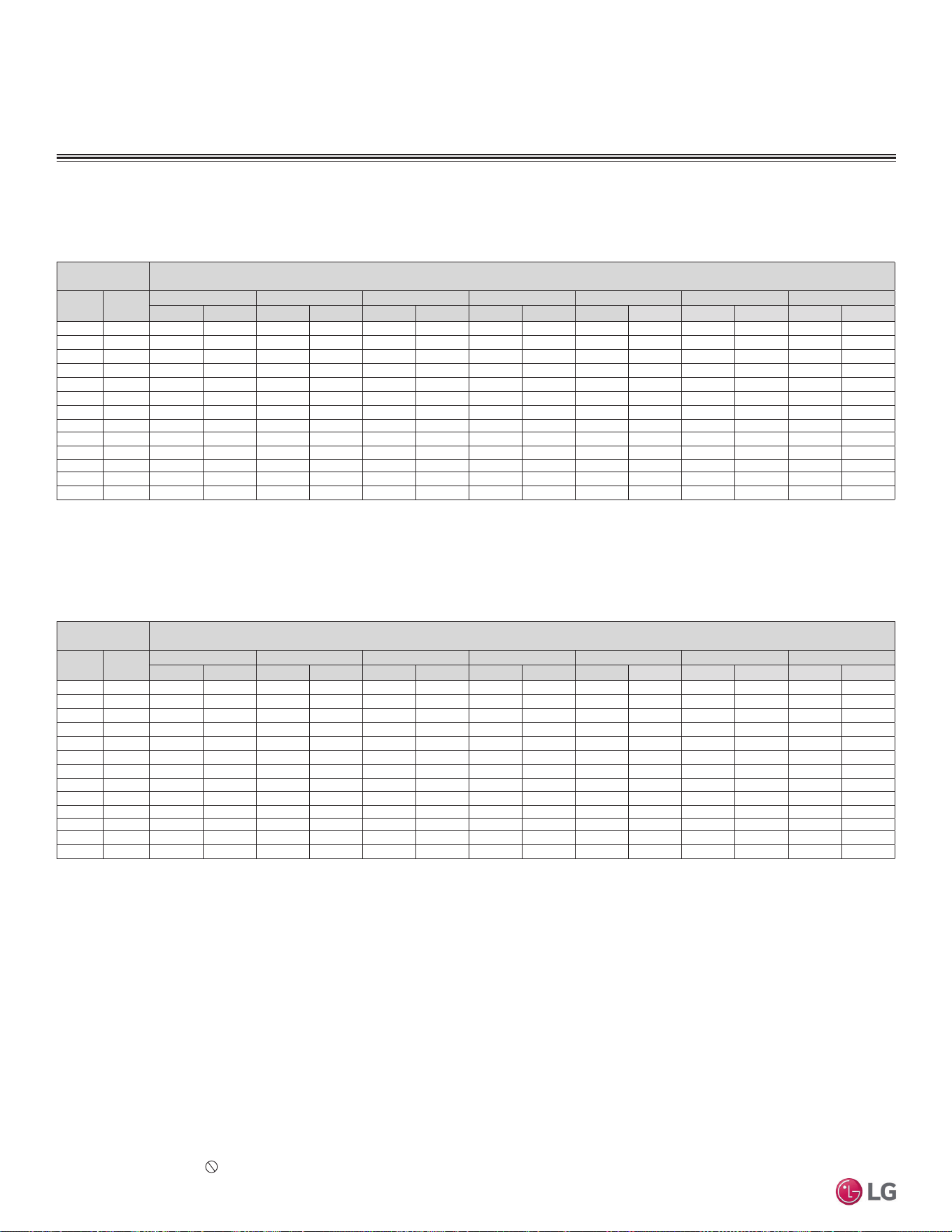
'XHWRRXUSROLF\RIFRQWLQXRXVSURGXFWLQQRYDWLRQVRPHVSHFL¿FDWLRQVPD\FKDQJHZLWKRXWQRWL¿FDWLRQ
©
/*(OHFWURQLFV86$,QF(QJOHZRRG&OLIIV1-$OOULJKWVUHVHUYHG³/*´LVDUHJLVWHUHGWUDGHPDUNRI/*&RUS
56 | PERFORMANCE DATA
Single Zone Mega Wall Mounted Engineering Manual
DB: Dry Bulb Temperature (°F) WB: Wet Bulb Temperature (°F) TC: Total Capacity (kBtu/h)
PI: Power Input (kW) (includes compressor,indoor fan motor and outdoor fan motor)
1. All capacities are net, evaporator fan motor heat is deducted.
2. Direct interpolation is permissible.
Do not extrapolate.
Nominal capacity as rated: 0 ft. above sea level with 24.6 ft. of refrigerant piping.
0 ft. level difference between outdoor and indoor units.
Nominal heating capacity rating obtained with air entering the indoor unit at 70ºF dry bulb (DB) and
60ºF wet bulb (WB), and outdoor ambient conditions of 47ºF dry bulb (DB) and 43ºF wet bulb (WB).
LS180HEV2, LS240HEV2
0D[LPXP+HDWLQJ&DSDFLW\
PERFORMANCE DATA
Maximum Heating Capacity Table for LS180HEV2 (LSU180HEV2 +
LSN180HEV2)
Table 29: LSN180HEV2 / LSU180HEV2 Heating Capacities.
Outdoor Air
Temp.
Indoor Air Temperature (°F DB)
°F DB °F WB
60 64 68 70 72 75 86
TC PI TC PI TC PI TC PI TC PI TC PI TC PI
16 14 16.89 2.53 16.65 2.57 16.41 2.61 16.30 2.62 15.82 2.58 15.15 2.53 12.55 2.34
17 15 17.53 2.56 17.28 2.60 17.04 2.63 16.93 2.65 16.43 2.59 15.75 2.51 12.99 2.23
19 17 18.51 2.57 18.26 2.60 18.01 2.62 17.68 2.64 17.32 2.58 16.53 2.49 13.48 2.19
24 23 20.32 2.59 20.05 2.59 19.79 2.60 19.67 2.61 18.88 2.54 17.82 2.44 13.90 2.10
32 30 22.15 2.50 21.87 2.51 21.59 2.51 21.47 2.52 20.44 2.43 19.03 2.32 14.03 1.90
41 38 23.90 2.32 23.61 2.37 23.32 2.42 23.19 2.44 21.99 2.33 20.36 2.18 14.79 1.62
43 40 24.61 2.22 24.32 2.26 24.03 2.31 23.90 2.33 22.64 2.22 20.92 2.06 15.08 1.49
47 43 26.10 2.13 25.80 2.21 25.50 2.29 25.26 2.32 24.01 2.19 22.17 2.02 15.95 1.38
53 50 25.72 2.08 25.39 2.15 25.06 2.22 25.14 2.25 23.44 2.11 21.42 1.91 14.70 1.17
59 53 25.42 2.03 25.39 2.12 25.37 2.21 25.14 2.24 23.75 2.10 21.56 1.90 14.50 1.18
64 57 25.86 1.98 25.47 2.02 25.07 2.05 24.89 2.07 23.36 1.94 21.26 1.77 14.35 1.15
70 61 25.96 1.88 25.50 1.88 25.03 1.88 24.82 1.88 23.30 1.76 21.23 1.61 14.42 1.04
75 65 26.33 1.70 25.79 1.75 25.24 1.81 24.78 1.83 23.45 1.71 21.35 1.55 14.29 0.95
Maximum Heating Capacity Table for LS240HEV2 (LSU240HEV2 +
LSN240HEV2)
Table 30: LSN240HEV2 / LSU240HEV2 Heating Capacities.
Outdoor Air
Temp.
Indoor Air Temperature (°F DB)
°F DB °F WB
60 64 68 70 72 75 86
TC PI TC PI TC PI TC PI TC PI TC PI TC PI
16 14 14.59 2.08 14.38 2.11 14.17 2.14 14.08 2.15 13.66 2.12 13.09 2.08 10.84 1.92
17 15 15.14 2.10 14.93 2.13 14.71 2.16 14.62 2.17 14.19 2.13 13.60 2.06 11.22 1.83
19 17 15.99 2.11 15.77 2.13 15.56 2.15 15.27 2.16 14.96 2.11 14.27 2.05 11.64 1.80
24 23 17.55 2.12 17.32 2.13 17.09 2.13 16.98 2.14 16.31 2.08 15.39 2.00 12.00 1.73
32 30 19.13 2.05 18.89 2.06 18.65 2.06 18.54 2.06 17.65 2.00 16.44 1.90 12.11 1.56
41 38 20.64 1.91 20.39 1.94 20.14 1.98 20.03 2.00 18.99 1.91 17.59 1.78 12.78 1.33
43 40 21.26 1.82 21.01 1.86 20.75 1.90 21.02 1.91 19.55 1.82 18.07 1.69 13.02 1.22
47 43 22.54 1.75 22.28 1.81 22.02 1.87 23.00 1.90 20.74 1.80 19.15 1.66 13.78 1.13
53 50 22.21 1.70 21.93 1.76 21.65 1.82 21.71 1.85 20.24 1.73 18.50 1.56 12.70 0.96
59 53 21.95 1.67 21.93 1.74 21.91 1.81 21.71 1.84 20.51 1.72 18.62 1.56 12.52 0.97
64 57 22.34 1.62 21.99 1.65 21.65 1.68 21.50 1.70 20.17 1.59 18.36 1.45 12.40 0.94
70 61 22.42 1.55 22.02 1.54 21.62 1.54 21.43 1.54 20.12 1.45 18.34 1.32 12.45 0.85
75 65 22.74 1.39 22.27 1.44 21.80 1.48 21.40 1.50 20.26 1.40 18.44 1.27 12.34 0.78
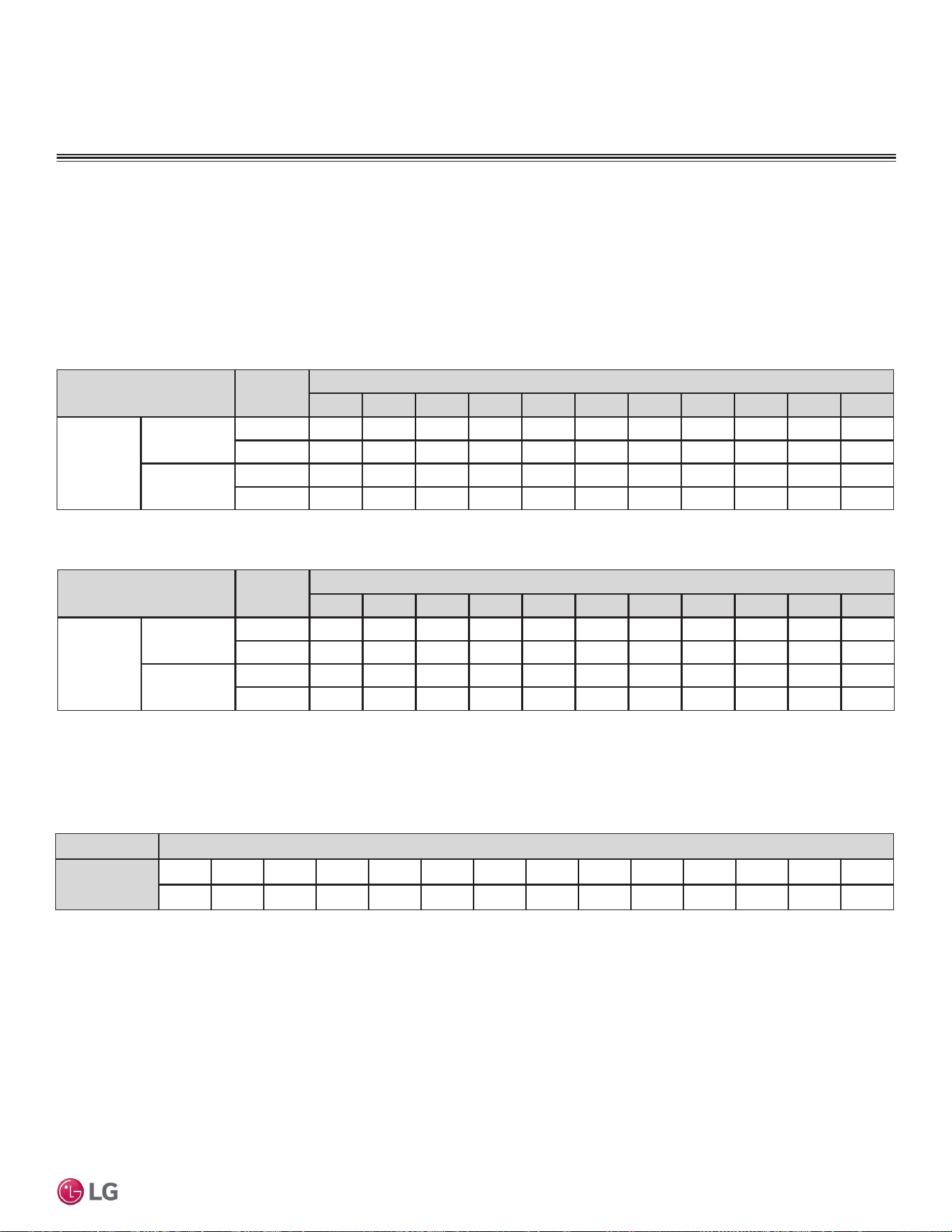
'XHWRRXUSROLF\RIFRQWLQXRXVSURGXFWLQQRYDWLRQVRPHVSHFL¿FDWLRQVPD\FKDQJHZLWKRXWQRWL¿FDWLRQ
©
/*(OHFWURQLFV86$,QF(QJOHZRRG&OLIIV1-$OOULJKWVUHVHUYHG³/*´LVDUHJLVWHUHGWUDGHPDUNRI/*&RUS
PERFORMANCE DATA | 57
Performance Data
EQUIPMENT SELECTION PROCEDURE
&RUUHFWLRQ)DFWRUV
Cooling / Heating Correction Factors
For Single Zone Mega Wall Mounted systems, calculate the equivalent length of the liquid line from the outdoor unit to the indoor unit. Also,
determine the elevation difference of the indoor unit above or below the outdoor unit. Find corresponding cooling or heating capacity correc-
tion factors as shown below. Multiply the correction factors by the cooling or heating capacity obtained from the capacity tables using design
conditions. The resultant is the NET cooling or heating capacity.
Cooling and Heating Capacity Coefficient Factors.
Table 31: 0HJD&RROLQJDQG+HDWLQJ&DSDFLW\&RHI¿FLHQW)DFWRUV
Operation
Mode
Piping Length (ft.)
16.4 24.6 32.8 49.2 65.6 82.0 98.4 114.8 131.2 147.6 164.0
Rate of
Capacity
Change (%)
LS-090HEV2
LS-120HEV2
Cooling 100 100 97.7 93.0 -------
Heating 100 100 98.3 95.0 -------
LS-180HEV2
LS-240HEV2
Cooling 100 100 99.0 97.0 95.0 - - - - - -
Heating 100 100 99.2 97.6 96.0 - - - - - -
Equivalent Piping Length for Piping Components
Component Size (Inches)
Elbow (ft.)
1/4 3/8 1/2 5/8 3/4 7/8 1 1-1/8 1-1/4 1-3/8 1-1/2 1-5/8 1-3/4 2-1/8
0.5 0.6 0.7 0.8 1.2 1.3 1.5 1.6 1.8 2.0 2.1 2.3 2.5 2.8
Table 32: 0HJD9&RROLQJDQG+HDWLQJ&DSDFLW\&RHI¿FLHQW)DFWRUV
Altitude Correction Factor
The impact of air density must be considered on systems installed at a significant altitude above sea level, therefore, locally accepted alti-
tude correction factors using ASHRAE guidelines must be applied.
Table 33: Equivalent Piping Length for Elbows.
Operation
Mode
Piping Length (ft.)
16.4 24.6 32.8 49.2 65.6 82.0 98.4 114.8 131.2 147.6 164.0
Rate of
Capacity
Change (%)
LS-090HXV
Cooling 100 100 95.8 87.5 - - - - - - -
Heating 100 100 95.8 93.8 - - - - - - -
LS-180HXV
Cooling 100 100 95.8 87.5 - - - - - - -
Heating 100 100 95.8 93.8 - - - - - - -
'XHWRRXUSROLF\RIFRQWLQXRXVSURGXFWLQQRYDWLRQVRPHVSHFL¿FDWLRQVPD\FKDQJHZLWKRXWQRWL¿FDWLRQ
©
/*(OHFWURQLFV86$,QF(QJOHZRRG&OLIIV1-$OOULJKWVUHVHUYHG³/*´LVDUHJLVWHUHGWUDGHPDUNRI/*&RUS
58 | PERFORMANCE DATA
Single Zone Mega Wall Mounted Engineering Manual
Table 34: Outdoor Unit Frost Accumulation Factor (Heating)
1
.
There will be a temporary reduction in capacity when frost / ice accumulates on the outside surface of the outdoor unit heat exchanger. The level of
capacity reduction depends on a number of factors, for example, outdoor temperature (°F DB), relative humidity (RH), and the amount of frost pres-
ent.
Entering DB (ºF)
19.4 23.0 26.6 32.0 37.4 41.0 44.6
Derate factor
0.98 0.95 0.93 0.86 0.93 0.96 1.0
1
At 85% outdoor air relative humidity.
The frost accumulation factor does not account for effects of snow accumulation restricting airflow
through the outdoor unit coil.
Defrost Correction Factor for Heating Operation
The outdoor unit heating capacity may need to be adjusted for frost accumulation on air-cooled systems. If design day conditions are below
the dewpoint of the surrounding air, frost may not be a problem and no correction factor is needed. In certain weather conditions, however,
frost may form and accumulate on the air-cooled outdoor unit coil and impact the coils ability to transfer heat. If significant frost accumulates
on the outdoor unit coil, a defrost algorithm will start automatically. The timing between defrost periods is determined by the system’s ability
to achieve a target head pressure value.
Capacity and AHRI ratings tables do not factor in capacity reduction when frost has accumulated on the condenser coil, nor during defrost
operation.
Integrated heating capacity values can be obtained using the formula:
A = B x C
Where:
A = Integrated Heating Capacity.
B = Value found in the Capacity Table.
C = Correction Factor for Frost Accumulation Factor (from table at
right).
EQUIPMENT SELECTION PROCEDURE
&RUUHFWLRQ)DFWRUV
Check the Indoor and Outdoor Unit Selection(s)
Compare the corrected cooling and heating capacities to the load calculations. Is each capacity sufficient for the zone it serves?
For each indoor unit, the corrected capacity must be at least equal to the total of the cooling design load (plus ventilation load, if applicable)
for the space served by the indoor unit. For each indoor unit, the corrected capacity also must be at least equal to the total of the heating
design load (plus ventilation load, if applicable) for the space(s) and / or thermal zones served by the indoor unit.
The outdoor unit selected must be large enough to offset the total cooling load for all spaces it serves (account for ventilation air cooling load
if the ventilation air has not been pretreated to room neutral conditions). The outdoor unit must also be large enough to offset the total heat-
ing load for all spaces it serves.
If the corrected heating capacity ratio exceeds 100%, reselect the equipment, or change the system design by moving some of the load to
another system.
• Understand the design safety factors.
• Reference load calculations for actual cooling and heating capacities (applies in 99% of applications – consider total load when latent load
is greater than 30%).
• Verify that the sensible load of the zone is satisfied.
• Use caution when sizing to meet listed capacity specifications for the scheduled manufacturer’s equipment.
If further system design assistance is needed, or you have a unique application you would like to discuss, contact your LG sales rep.
1. Outdoor Unit Rated Capacity.
Q
odu(rated)
(From capacity tables).
2. Outdoor Unit Capacity at Ti, To Temperature.
Q
odu(Ti, To)
(From capacity tables).
3 Outdoor Unit Capacity Coefficient Factor.
F
(Ti, To)
= Q
odu(Ti, To)
/ Q
odu(rated)
4. Piping Correction Factor (From Capacity Coefficient
Factor Tables).
F
(length)
for each piping length
5. Individual Indoor Unit Combination Capacity.
Q
idu (combi)
= Q
odu(rated)
x Q
idu(rated)
/ Q
idu(rated-total)
6. Individual Indoor Unit Actual Capacity.
Q
idu (actual)
= Q
odu(combi)
x F
(Ti, To)
x F
(length, altitude)
System Sizing Check Formulas
Conclusions and Recommendations

Placement Considerations on page 60
Installing Outdoor Units Indoors on page 65
Design Guideline Summary on page 68
APPLICATION
GUIDELINES
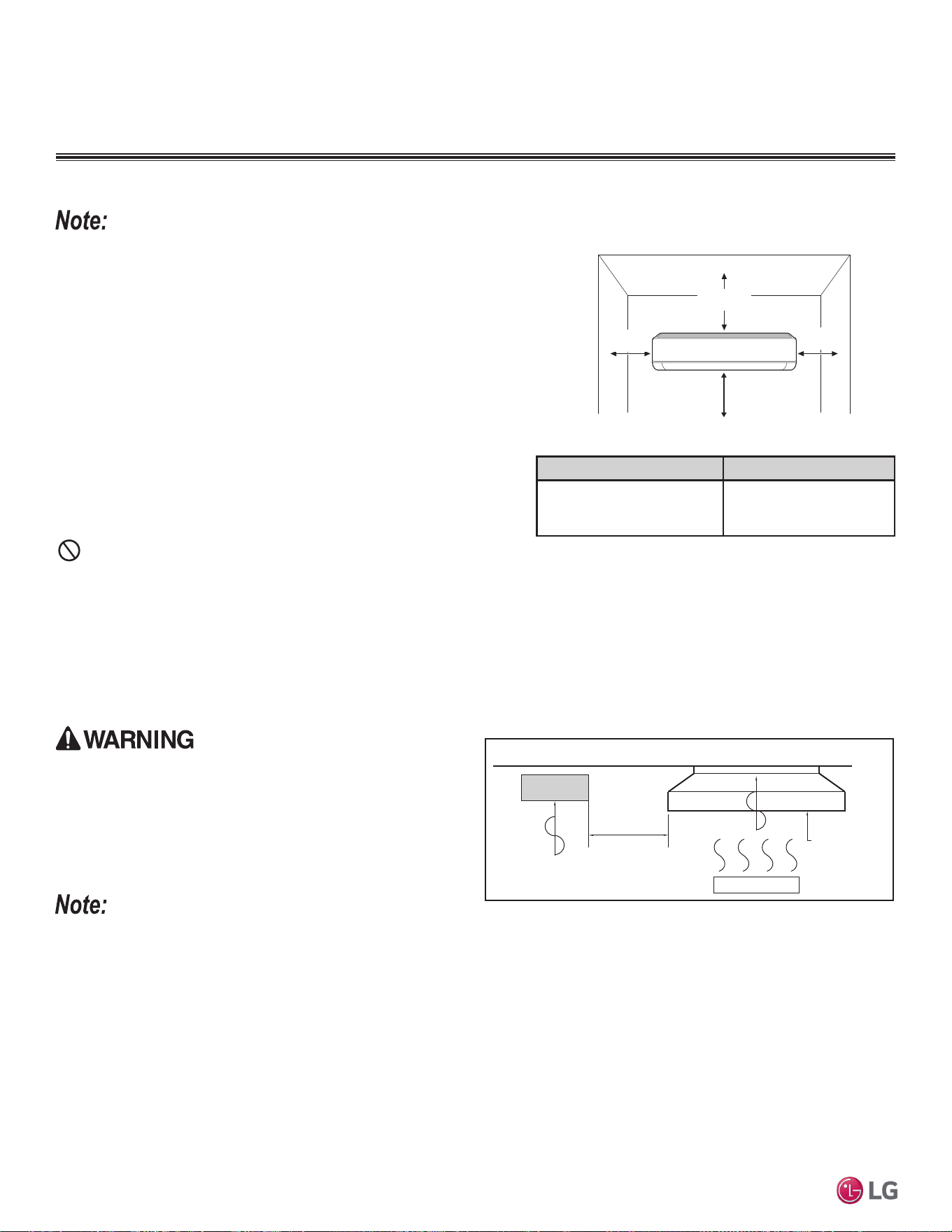
60 | APPLICATION GUIDELINES
Single Zone Mega Wall Mounted Engineering Manual
'XHWRRXUSROLF\RIFRQWLQXRXVSURGXFWLQQRYDWLRQVRPHVSHFL¿FDWLRQVPD\FKDQJHZLWKRXWQRWL¿FDWLRQ
©
/*(OHFWURQLFV86$,QF(QJOHZRRG&OLIIV1-$OOULJKWVUHVHUYHG³/*´LVDUHJLVWHUHGWUDGHPDUNRI/*&RUS
PLACEMENT CONSIDERATIONS
Selecting the Best Location for the Indoor Unit
Follow recommended best practices when choosing an indoor location for the
single zone indoor unit.
Dos
• Follow the table at right for minimum clearance of indoor unit from the top of
the unit to the ceiling.
• Clearance gap between any wall or enclosure and the left or right side of the
unit must be greater than 4 inches. Ensure there is sufficient maintenance
space.
• Unit must be at least 6.5 feet from the floor for adequate clearance.
• Place the unit where drainage can be obtained easily. Condensation drain
must be conveniently routed away from the unit.
• Locate the indoor unit in a location where it can be easily connected to the
outdoor unit within allowable limits.
• Use a metal detector to locate studs in the walls. Anchor unit following stud
location to prevent damage to the wall.
Dont’s
• Do not install the unit near a heat or steam source, or where considerable amounts of oil, iron powder, or flour are used. (These materials
will generate condensate, cause a reduction in heat exchanger efficiency, or the drain to malfunction. If this is a potential problem, install a
ventilation fan large enough to vent out these materials.)
• Ensure there are no obstacles to air circulation around the unit; keep proper distances from ceilings, doorways, floor, walls, etc.
• Do not install in an area where operation sound will disturb occupants--place the unit where noise prevention is taken into consideration
• Do not install near doorway.
• Avoid installing the unit near high-frequency generators.
Figure 28: Mega Indoor Unit Clearance Requirements.
Ceiling Clearance (inches) Indoor Unit Model(s)
8
LSN090HEV2, LSN120HEV2,
LSN180HEV2, LSN240HEV2
LSN090HXV, LSN120HXV
Table 35: Mega Indoor Unit Ceiling Clearance.
>4 (100)
Unit: Inch (mm)
>4 (100)
>8 (200)
At least 6-1/2 feet from the floor
7KHXQLWPXVWQRWEHLQVWDOOHGZKHUHVXOIXULFDFLGDQGÀDPPDEOHRUFRU-
URVLYHJDVHVDUHJHQHUDWHGYHQWHGLQWRRUVWRUHG7KHUHLVULVNRI¿UH
explosion, and physical injury or death.
The unit will be damaged, will malfunction, and / or will not
operate as designed if installed in any of the conditions
listed.
• Indoor units (IDUs) must not be placed in an environment where the IDUs will be exposed to harmful volatile organic compounds (VOCs) or
in environments where there is improper air make up or supply or inadequate ventilation. If there are concerns about VOCs in the environ-
ment where the IDUs are installed, proper air make up or supply and/ or adequate ventilation must be provided. Additionally, in buildings
where IDUs will be exposed to VOCs consider a factory-applied epoxy coating to the fan coils for each IDU.
• If the unit is installed near a body of water, the installation parts are at risk of corroding. Appropriate anti-corrosion methods must be taken
for the unit and all installation parts.
Installing in an Area Exposed to Unconditioned Air
In some installation applications, areas (floors, walls) in some rooms will be exposed to unconditioned air (room will be above or next to an
unheated garage or storeroom). To countermeasure:
• Verify that carpet is or will be installed (carpet will increase the temperature by three [3] degrees).
• Add insulation between the floor joists.
• Install radiant heat or another type of heating system to the floor.
Install a ventilation fan
with sufficient capacity
Heat or steam source
Include enough
distance
Indoor Unit
Figure 29: Installing Near a Heat or Steam Source.
,QGRRU8QLW
APPLICATION GUIDELINES | 61
Application Guidelines
'XHWRRXUSROLF\RIFRQWLQXRXVSURGXFWLQQRYDWLRQVRPHVSHFL¿FDWLRQVPD\FKDQJHZLWKRXWQRWL¿FDWLRQ
©
/*(OHFWURQLFV86$,QF(QJOHZRRG&OLIIV1-$OOULJKWVUHVHUYHG³/*´LVDUHJLVWHUHGWUDGHPDUNRI/*&RUS
Selecting the Best Location for the Outdoor Unit
DANGER
• Do not install the unit in an area where combustible gas will generate, flow, stagnate, or leak. These conditions can cause a fire, result-
ing in bodily injury or death.
• Do not install the unit in a location where acidic solution and spray (sulfur) are often used as it can cause bodily injury or death.
• Do not use the unit in environments where oil, steam, or sulfuric gas are present as it can cause bodily injury or death.
When deciding on a location to place the outdoor unit, be sure to choose an area where run-off from defrost will not accumulate and freeze on
sidewalks or driveways, which will create unsafe conditions. Properly install and insulate any drain hoses to prevent the hose from freezing, cracking,
leaking, and causing unsafe conditions from frozen condensate.
Install a fence to prevent vermin from crawling into the unit or unauthorized individuals from accessing it. Vermin and unauthorized individuals will
cause a fire, electric shock, physical injury or death. Follow the placement guidelines set forth in “Clearance Requirements”.
Install a fence to prevent vermin from crawling into the unit or unauthorized individuals from accessing it. Vermin and unauthorized individuals will
damage the unit. Follow the placement guidelines set forth in “Clearance Requirements”.
Select a location for installing the outdoor unit that will meet the following conditions:
• Where there is enough strength to bear the weight of the unit.
• A location that allows for optimum air flow and is easily accessible for inspection, maintenance, and service.
• Where piping between the outdoor unit and indoor unit is within allowable limits.
• Include space for drainage to ensure condensate flows properly out of the unit when it is in heating mode.
Avoid placing the outdoor
unit in a low-lying area where water could accumulate.
• If the outdoor unit is installed in a highly humid environment (near an ocean, lake, etc.), ensure that the site is well-ventilated and has a lot
of natural light (Example: Install on a rooftop).
Dont’s
• Where it will be subjected to direct thermal radiation from other heat sources, or an area that would expose the outdoor unit to heat or
steam like discharge from boiler stacks, chimneys, steam relief ports, other air conditioning units, kitchen vents, plumbing vents, and other
sources of extreme temperatures.
• Where high-frequency electrical noise / electromagnetic waves will affect operation.
• Where operating sound from the unit will disturb inhabitants of surrounding buildings.
• Where the unit will be exposed to direct, strong winds.
• Where the discharge of one outdoor unit will blow into the inlet side of an adjacent unit (when installing multiple outdoor units).
Planning for Snow and Ice
To ensure the outdoor unit operates properly, certain measures are required in locations where there is a possibility of heavy snowfall or
severe windchill or cold:
1. Prepare for severe winter wind chills and heavy snowfall, even in areas of the country where these are unusual phenomena.
2. Position the outdoor unit so that its airflow fans are not buried by direct, heavy snowfall. If snow piles up and blocks the airflow, the sys-
tem will malfunction.
3. Remove any snow that has accumulated four (4) inches or more on the top of the outdoor unit.
4. In climates that will experience significant snow buildup, mount the outdoor unit on a raised, field-provided platform or stand. The raised
support platform must be high enough to allow the unit to remain above possible snow drifts, and must be higher than the maximum antici-
pated snowfall for the location.
5. Design the mounting base to prevent snow accumulation on the platform in front or back of the unit frame.
6. Provide a field fabricated snow protection hood to keep snow and ice and/or drifting snow from accumulating on the coil surfaces.
7. To prevent snow and heavy rain from entering the outdoor unit, install the condenser air inlets and outlets facing away from direct winds.
8. Consider tie-down requirements in case of high winds or where required by local codes.
Outdoor Unit Condensate Drain Piping
Outdoor unit requires condensate drain piping. Condensate drain pipe is constructed with materials approved by local code. See page 64 for
information in reference to outdoor unit placement.
PLACEMENT CONSIDERATIONS
2XWGRRU8QLW
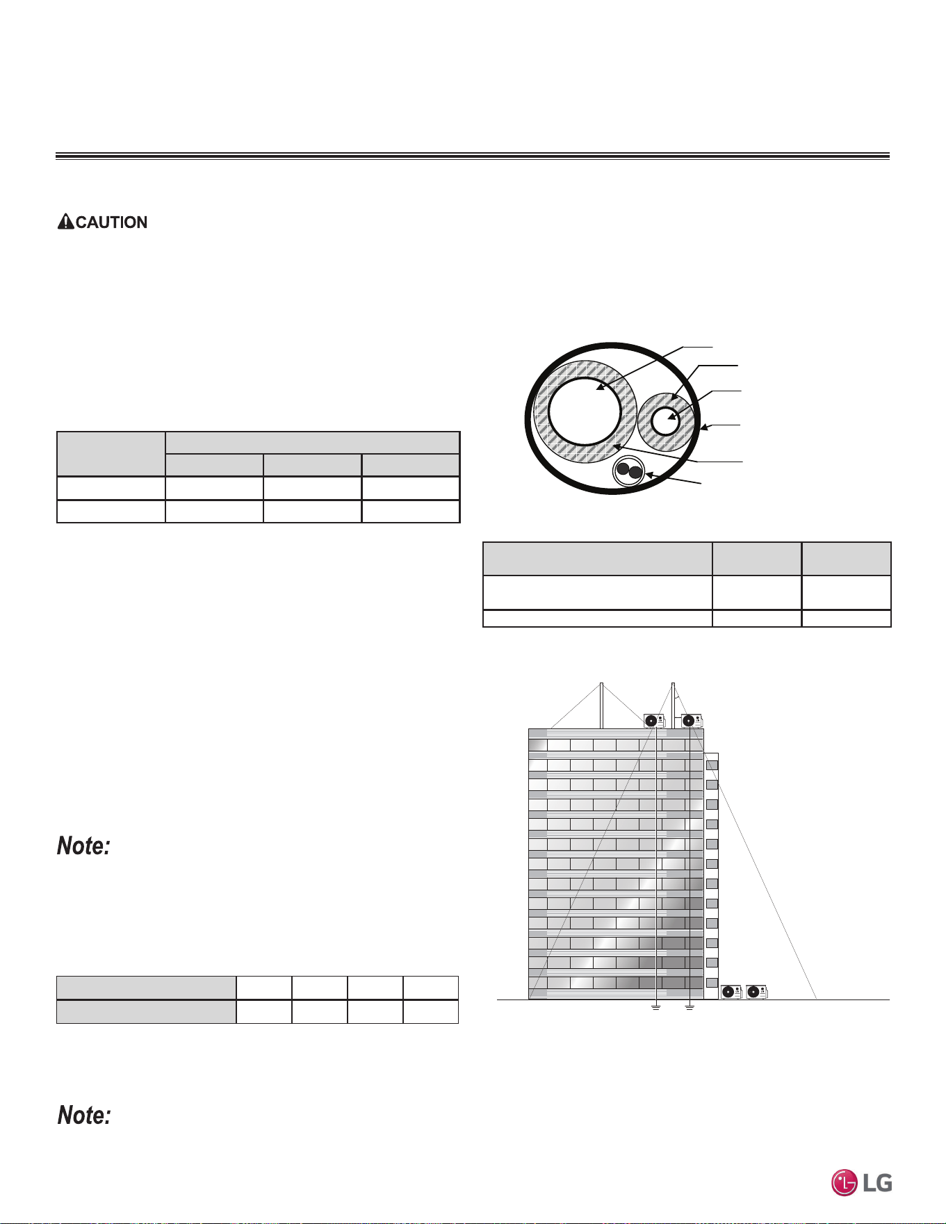
62 | APPLICATION GUIDELINES
Single Zone Mega Wall Mounted Engineering Manual
'XHWRRXUSROLF\RIFRQWLQXRXVSURGXFWLQQRYDWLRQVRPHVSHFL¿FDWLRQVPD\FKDQJHZLWKRXWQRWL¿FDWLRQ
©
/*(OHFWURQLFV86$,QF(QJOHZRRG&OLIIV1-$OOULJKWVUHVHUYHG³/*´LVDUHJLVWHUHGWUDGHPDUNRI/*&RUS
When deciding on a location to place the outdoor unit, be sure to choose an area where run-off from defrost will not accumulate and freeze on
sidewalks or driveways, which will create unsafe conditions. Properly install and insulate any drain hoses to prevent the hose from freezing, cracking,
leaking, and causing unsafe conditions from frozen condensate.
Planning for Snow and Ice, continued.
Tie-Downs and Lightning Protection
Tie-Downs
• The strength of the roof must be checked before installing the
outdoor units.
• If the installation site is prone to high winds or earthquakes, when
installing on the wall or roof, securely anchor the mounting base
using a field-provided tie-down configuration approved by a local
professional engineer.
• The overall tie-down configuration must be approved by a local
professional engineer.
Always refer to local code when using a wind restraint system.
Lightning Protection
• To protect the outdoor unit from lightning, it must be placed within
the specified lightning safety zone.
• Power cable and communication cable must be installed five (5) feet away from lightning rod.
• A high-resistance ground system must be included to protect against induced lightning or indirect strike.
Building Height (feet)
66 98 148 197
3URWHFWLRQ$QJOHÛ
55 45 35 25
If the building does not include lightning protection, the outdoor unit will be damaged from a lightening strike. Inform the customer of this possibility in
advance.
Figure 30: Typical Arrangement of Refrigerant Pipe and Cable(s) in a
Utility Conduit.
Ground
Safe zone
Lightning rod
3URWHFWLRQ$QJOHÛaÛ
5 feet
Lightning rod
Underground Refrigerant Piping
Refrigerant pipe installed underground must be routed inside a vapor
tight protective sleeve to prevent insulation deterioration and water
infiltration. Refrigerant pipe installed inside underground
casing must be continuous without any joints. Underground refriger-
ant pipe must be located at a level below the frost line.
Figure 31: Lightning Protection Diagram.
Table 36: Utility Conduit Sizes (Inches).
1
OD pipe diameter in inches; Values in parenthesis () indicate OD of pipe with insulation jacket.
2
Diameter of pipe with insulation. Thickness of pipe insulation is typical. Actual required thickness will
vary based on surrounding ambient conditions and must be calculated and specified by the design
engineer.
3
Insulation thickness (value in parenthesis) = 3/8 inch.
4
Insulation thickness (value in parenthesis) = 3/4 inch.
Liquid Pipe
1
Vapor Pipe
1
3/8 (2.0
2,3
) 1/2 (2.0
2,4
) 5/8 (2-1/8
2,4
)
1/4 (1.0)
4
444
3/8 (1-1/8)
4
444
Table 37: Outdoor Unit Refrigerant Pipe Connections.
Vapor Line
Liquid Line
Min. 18 Gauge
Cable
Power/Communication
Pi
p
e Sleeve
Insulation Material
Insulation
Material
Model
Liquid Conn.
(inches)
Vapor Conn.
(inches)
LS090HEV2, LS120HEV2,
LS090HXV, LS120HXV
1/4 3/8
LS180HEV2, LS240HEV2 1/4 1/2
Table 38: Safety Zone Specifications.
PLACEMENT CONSIDERATIONS
2XWGRRU8QLW
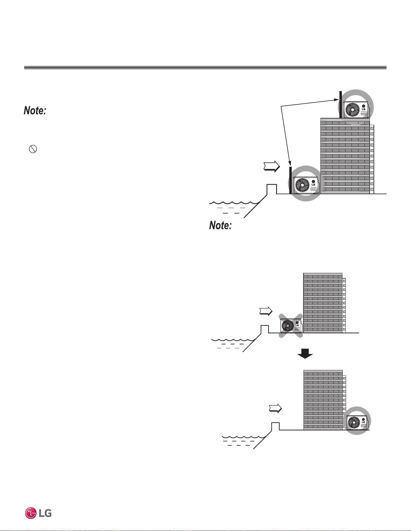
APPLICATION GUIDELINES | 63
Application Guidelines
'XHWRRXUSROLF\RIFRQWLQXRXVSURGXFWLQQRYDWLRQVRPHVSHFL¿FDWLRQVPD\FKDQJHZLWKRXWQRWL¿FDWLRQ
©
/*(OHFWURQLFV86$,QF(QJOHZRRG&OLIIV1-$OOULJKWVUHVHUYHG³/*´LVDUHJLVWHUHGWUDGHPDUNRI/*&RUS
• Avoid installing the outdoor unit where it would be directly
exposed to ocean winds.
• Install the outdoor unit on the side of the building opposite from
direct ocean winds.
• Select a location with good drainage.
• Periodically clean dust or salt particles off of the heat exchanger
with water.
• If the outdoor unit must be placed in a location where it would
be subjected to direct ocean winds, install a concrete windbreak
strong enough to block any winds.
• Windbreak must be more than 150% of the outdoor unit’s height.
There must be 2 to 3-1/2 inches of clearance between the outdoor
unit and the windbreaker for purposes of air flow.
Additional anti-corrosion treatment will need to be applied to the outdoor
unit at oceanside locations.
Ocean winds will cause corrosion, particularly on the condenser and
HYDSRUDWRU¿QVZKLFKLQWXUQFRXOGFDXVHSURGXFWPDOIXQFWLRQRU
LQHI¿FLHQWSHUIRUPDQFH
Figure 32: Oceanside Placement Using Windbreak.
Figure 33: Placement Using Building as Shield.
Oceanside Applications
Use of a Windbreak to Shield from Sea Wind
Sea wind
Windbreak
Use of a Building to Shield from Sea Wind
If a windbreak is not possible, a building or larger structure must be
used to shield the outdoor unit from direct exposure to the sea wind.
The unit must be placed on the side of the building directly opposite
to the direction of the wind as shown in the figure at right.
Sea wind
Sea wind
Building
Building
PLACEMENT CONSIDERATIONS
2XWGRRU8QLW
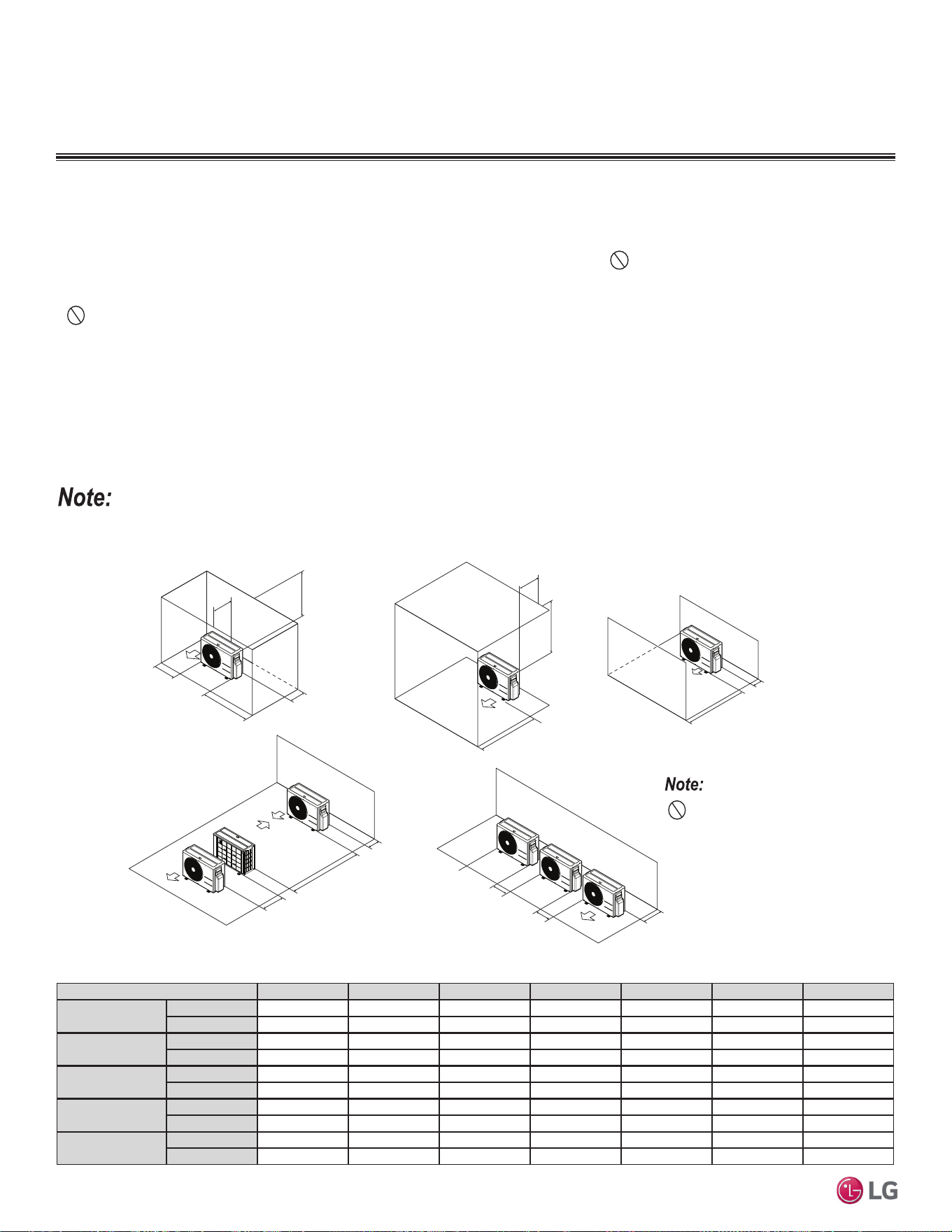
64 | APPLICATION GUIDELINES
Single Zone Mega Wall Mounted Engineering Manual
'XHWRRXUSROLF\RIFRQWLQXRXVSURGXFWLQQRYDWLRQVRPHVSHFL¿FDWLRQVPD\FKDQJHZLWKRXWQRWL¿FDWLRQ
©
/*(OHFWURQLFV86$,QF(QJOHZRRG&OLIIV1-$OOULJKWVUHVHUYHG³/*´LVDUHJLVWHUHGWUDGHPDUNRI/*&RUS
Mega and Mega 115V Outdoor Unit Service Access and Allowable Clearances
Specific clearance requirements in the diagram below are for all Mega outdoor units. The figure below shows the overall minimum clearances
that must be observed for safe operation and adequate airflow around the outdoor unit.
When placing the outdoor unit under an overhang, awning, sunroof or other “roof-like structure”, observe the clearance requirements (as
shown in Cases 1 and 2) for height in relation to the unit. To have successful service access to the outdoor unit, see figure below for mini-
mum spacing. When installing multiple outdoor units, see Cases 4 and 5 for correct spacing requirements.
Figure 34: Single Zone Mega and Mega 115V Outdoor Unit Service Access and Allowable Clearances Diagram.
Unit: Inch A B C D E F G
Case 1
Standard
12 24 - 12 - - -
Minimum
410-4--40
Case 2
Standard
--20----
Minimum
- - 14 - - - 40
Case 3
Standard
- - 20 12 - - -
Minimum
--144---
Case 4
Standard
---1224--
Minimum
---4879-
Case 5
Standard
-24-12- - -
Minimum
-10- 4 - - -
Table 39: Single Zone Mega and Mega 115V Outdoor Unit Service Access and Allowable Clearances Diagram Legend.
Do not place the unit where animals
and/or plants will be in the path of the
warm air, or where the warm air and/or
noise will disturb neighbors.
If the outdoor unit is installed between standard and minimum clearances, capacity decreases approximately 10%.
Minimum Allowable Clearance and Service Access Requirements
Proper clearance for the outdoor unit coil is critical for proper operation. When installing the outdoor unit, consider service, inlet and outlet,
and minimum allowable space requirements as illustrated in the diagrams below.
• Include enough space for airflow and for service access. If installing multiple outdoor units, avoid placing the units where the discharge
of one unit will blow into the inlet side of an adjacent unit.
• If an awning is built over the unit to prevent direct sunlight or rain exposure, make sure that the discharge air of the outdoor unit isn’t restricted.
• No obstacles to air circulation around the unit; keep proper distances from ceilings, fences, floor, walls, etc. (Install a fence to prevent
pests from damaging the unit or unauthorized individuals from accessing it.)
A
B
D
G
C
G
C
D
E
D
D
B
B
F
1/16 inch
20 inches or less
Case 1
Case 4
Case 2 Case 3
Case 5
20 inches or less
PLACEMENT CONSIDERATIONS
2XWGRRU8QLW

APPLICATION GUIDELINES | 65
Application Guidelines
'XHWRRXUSROLF\RIFRQWLQXRXVSURGXFWLQQRYDWLRQVRPHVSHFL¿FDWLRQVPD\FKDQJHZLWKRXWQRWL¿FDWLRQ
©
/*(OHFWURQLFV86$,QF(QJOHZRRG&OLIIV1-$OOULJKWVUHVHUYHG³/*´LVDUHJLVWHUHGWUDGHPDUNRI/*&RUS
PLACEMENT CONSIDERATIONS
Installing Outdoor Units Indoors
Single Zone Mega and Mega 115V Wall Mount outdoor units are engineered to be mounted outdoors and include technology designed to
minimize the negative effects of winter weather’s freezing rain, sleet, and snow. Some building projects, however, necessitate placing the
HVAC outdoor units indoors:
• Lack of ground space.
• Lack of an appropriate outdoor location that meets system design requirements.
• When mounting on the roof is not an option due to a lack of roof space.
• Roof warranty will be voided if mechanical equipment is placed on the membrane.
• On retrofit projects, a former chiller / boiler / air handler equipment room, mechanical area, or penthouse already exists.
• To curtail the potential need for redundant zone heating devices such as wall-fin radiators or duct heaters.
• In extremely cold environments where there is a significant amount of run-time at temperatures well below freezing outside the outdoor unit
ambient air temperature range published in this engineering manual.
Benefits of Installing Outdoor Units Indoors
• Shelters the outdoor unit from direct exposure to prevailing winds that decrease the heating capability of the outdoor unit.
• Protects equipment from freezing precipitation and / or potential ice build-up that could hinder unit operation.
• Maintains coil heat transfer efficiency by reducing the number of and shortening the cycle time for defrost operation.
• Easier maintenance and servicing during inclement weather.
• When mounted in a fully enclosed space, limiting the ambient air temperature will allow the Single Zone Mega and Mega 115V Wall Mount
system designer to eliminate oversizing.
• The outdoor unit to compensate for loss of capacity at low ambient temperatures.
• Will also curtail the need to provide inefficient redundant zone heating devices such as wall-fin radiators and second-stage ancillary heating
devices.
Design Considerations Include:
• Enclosure types and elements such as louvers (see next page), rain hoods, dampers and controls, heating methods and sizing of heating
devices.
• Heating strategies.
• Duct design.
• Condensate handling.
General Guidelines
• Follow ASHRAE 62.1 design guidelines.
• Depending on the project / application, a roof over the outdoor units in combination with a wind break will be all that is necessary.
• Consider the potential for snow accumulation near louvers / roof openings. Outside air intakes and discharge ducts/louvers must be engi-
neered to clear anticipated snow accumulation levels by at least one (1) foot.
• In situations where operation is anticipated at temperatures lower than the product’s minimum operating temperature, ancillary heat must
be provided to heat the outdoor unit coils to ensure continuous compressor operation and heating.
It will be necessary to use a field-fabricated air guide to prevent discharge air from short-cycling back to the coil inlet.
• Consider the direction of prevailing winds and opening placement. If possible, locate inlet openings upwind of discharge openings and other
exhaust outlets.
• When inlet and outlet openings are placed on the same wall, minimum distance between the two openings must be approximately three (3)
feet (minimum distance varies significantly with variations in outlet opening face velocity).
• If roof-mounted ventilation openings are used, strategically locate the inlet ventilation opening(s) upwind of the outlet opening(s).
• Discharge and supply ductwork must be designed to avoid weather related long periods of water entrainment and the potential for microbial
growth.
,QVWDOOLQJ2XWGRRU8QLWV,QGRRUV
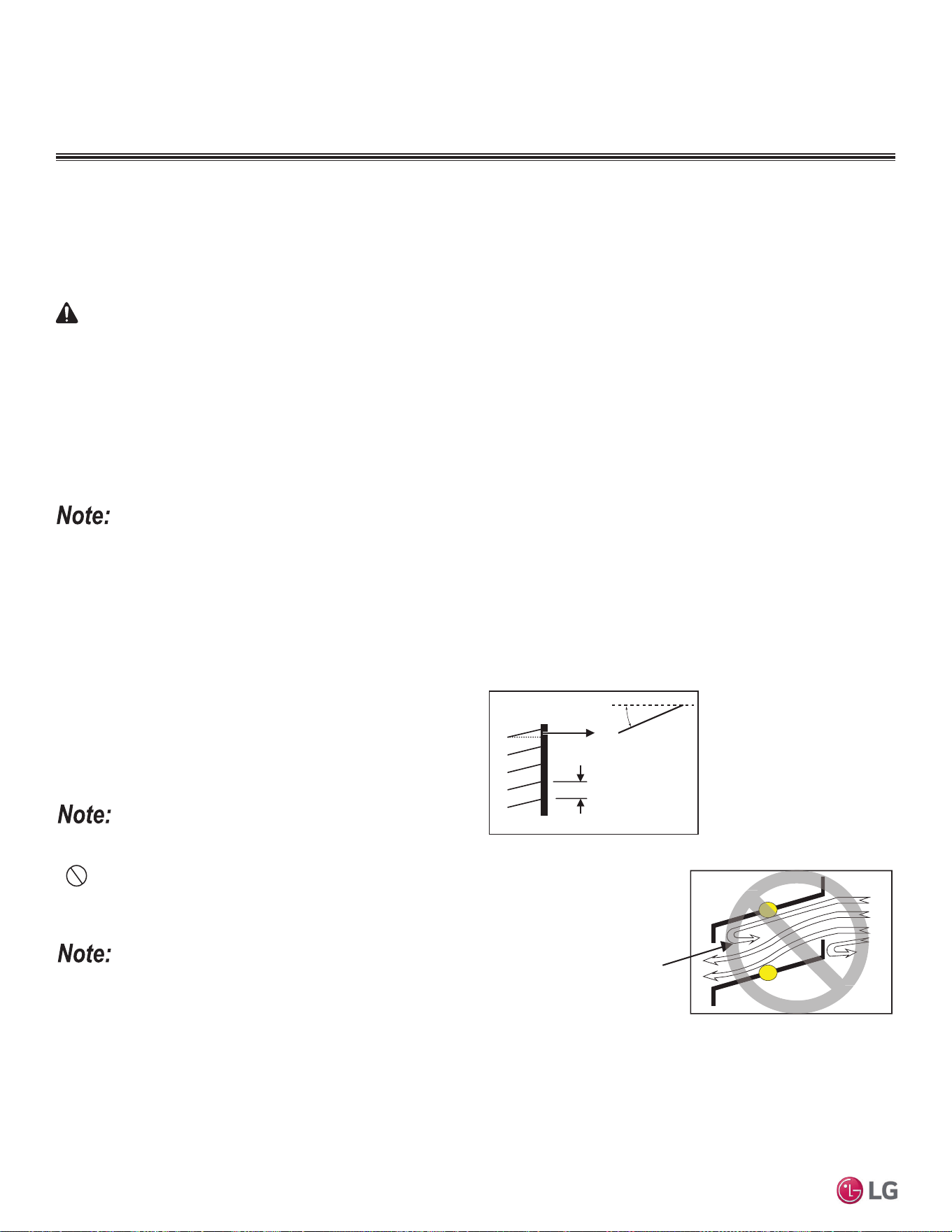
66 | APPLICATION GUIDELINES
Single Zone Mega Wall Mounted Engineering Manual
'XHWRRXUSROLF\RIFRQWLQXRXVSURGXFWLQQRYDWLRQVRPHVSHFL¿FDWLRQVPD\FKDQJHZLWKRXWQRWL¿FDWLRQ
©
/*(OHFWURQLFV86$,QF(QJOHZRRG&OLIIV1-$OOULJKWVUHVHUYHG³/*´LVDUHJLVWHUHGWUDGHPDUNRI/*&RUS
1. Outdoor Unit Enclosure: Manual Door Open Type.
2. Louver Angle: No More Than 15° Horizontally.
3. Space Between Louvers: More than 4 inches (Recommend).
4. Louver Shape: Wing or Plane Type.
Inside
Outside
Air flow passing through
the louver blade backwards
can generate noise.
In
side
Maximum 15°
(Recommended)
More than 4 in.
(Recommended)
Louver
• Open Rate and Inlet must be taken into consideration when design-
ing the louvered outdoor unit enclosure.
• Do not use “S” type louvers.
If the Louver Open Rate is Too Small
1. Noise can occur because of the increased air velocity passing
through the louver blade.
2. Noise can occur from louver blade vibrations.
3. A drop in outdoor unit fan performance (excess static pressure
can cause a drop in outdoor unit performance and heat exchanger
efficiency).
4. If the louver open rate is too small or there is insufficient air flow
exchange, the air conditioner might stop operating.
Figure 35: Louver Recommendations.
Figure 36: Using “S” Type Louvers.
Provide a means to drain the condensate generated during heating mode and defrost cycle in addition to rainwater that infiltrates the inlet
louver enclosed area.
• Install a field-provided drain pan under the outdoor units and provide a path to a nearby floor drain.
• If the ambient air temperature is expected to drop below 32°F in the enclosure, heat the bottom surface of the pan, drain line, and floor
drain so that the condensate does not freeze before reaching the drain.
Louver Recommendations for Outdoor Unit Enclosure
Allow for ventilation intake and exhaust air based on maximum outdoor unit fan capacity.
• Select the size, type and orientation of architectural louvers with adequate “net free area” face velocity to ensure the total external static
pressure from the outdoor unit fan does not exceed design limitations (see specification data tables).
• No obstructions must be placed in front of the louver that could hamper the free flow (throw) of air.
• Roof top openings and / or discharge and supply louvers must be equipped with screens to prevent bird and insect infiltration.
For louver recommendations, see below and on the next page.
As always, the best solution for each project balances acceptable heating performance (considering local weather conditions), capital costs,
life cycle energy consumption, and limitations set forth by local building codes.
When deciding on a location to place the outdoor unit, be sure to choose an area where run-off from defrost will not accumulate and freeze on side-
walks or driveways which will create unsafe conditions.
CAUTION
PLACEMENT CONSIDERATIONS
,QVWDOOLQJ2XWGRRU8QLWV,QGRRUV
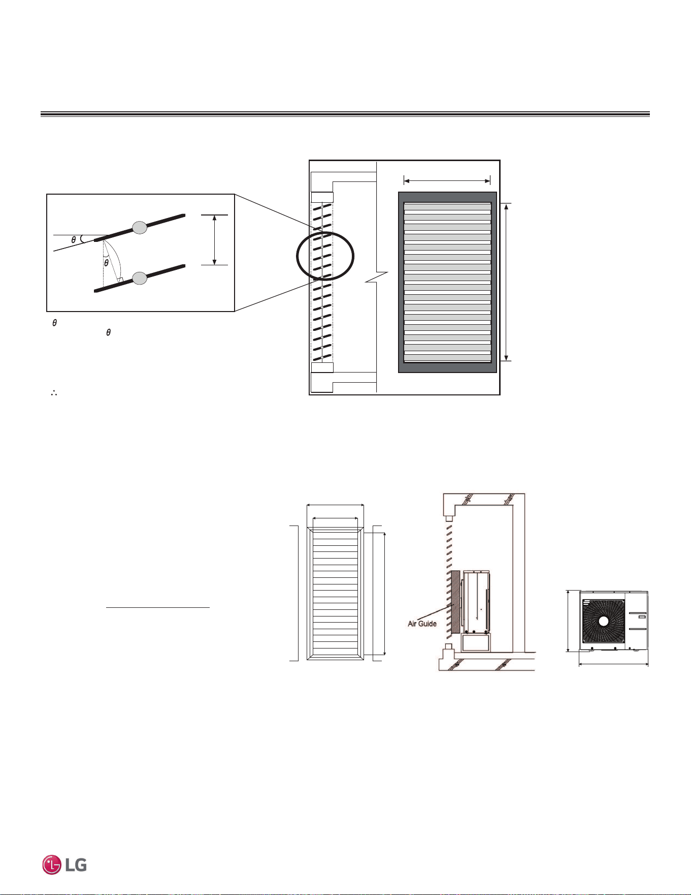
APPLICATION GUIDELINES | 67
Application Guidelines
'XHWRRXUSROLF\RIFRQWLQXRXVSURGXFWLQQRYDWLRQVRPHVSHFL¿FDWLRQVPD\FKDQJHZLWKRXWQRWL¿FDWLRQ
©
/*(OHFWURQLFV86$,QF(QJOHZRRG&OLIIV1-$OOULJKWVUHVHUYHG³/*´LVDUHJLVWHUHGWUDGHPDUNRI/*&RUS
Formula
• Total Louver Dimension (Excluding Frame) (A) = 3.9 feet x 6.2 feet = 24.2 ft.
2
• Area Blocked by Outdoor Unit (Discharge) (B) = 2.6 feet x 2.8 feet = 7.41 ft.
2
• Inlet Louver Dimension (A - B) = 16.8 ft.
2
• Equivalent Inlet Dimension (Open Rate 80%) = 16.8 ft.
2
x 0.8 = 13.44 ft.
2
• Equivalent Inlet Airflow = 13.44 ft.
2
x 8.2 ft./s x 60 sec./min. = 6,612 ft.
3
/min.
• Equivalent Inlet Airflow / Discharge Airflow = 6,612 ft.
3
/min. / 2,119 ft.
3
/min. = 312% (Within Allowable Limits)
Confirming Air Flow Rate / Total Opening Rate
• Example: LSU180HSV5.
• Discharge Airflow Rate: 2,119 ft.
3
/min.
• Velocity of Outlet Air: 16.4 ft./s
• Velocity of Inlet Air: 8.2 ft./s
• Open Rate = 80% or More
• Inlet airflow must match or exceed discharge airflow.
• Separate inlet airflow from discharge airflow to
prevent recirculation.
Figure 37: Open Rate by Louver Radian Formula.
Open Rate = Effective Face Area (Af)
Total Face Area (A)
Side View
ho = h * COS
Total Area (A) = H * W
Number of Open Spaces (N) = (Number of Louvers - 1)
Effective Area (Af) = ho * W * N
Louver Open Rate (n) = Af / A
Af = A * n
Effective Cross Section Area
ho
h
W
Front View
H
Open Rate by Louver Radian
Figure 38: Example of Installing Outdoor Unit Indoors.
PLACEMENT CONSIDERATIONS
,QVWDOOLQJ2XWGRRU8QLWV,QGRRUV
55-1/8
47-1/4
34-1/4
74-13/16
31-1/2
Unit: Inch
Louver Dimensions Air Guide Duct on
Outdoor Unit
Outdoor Unit
Dimensions
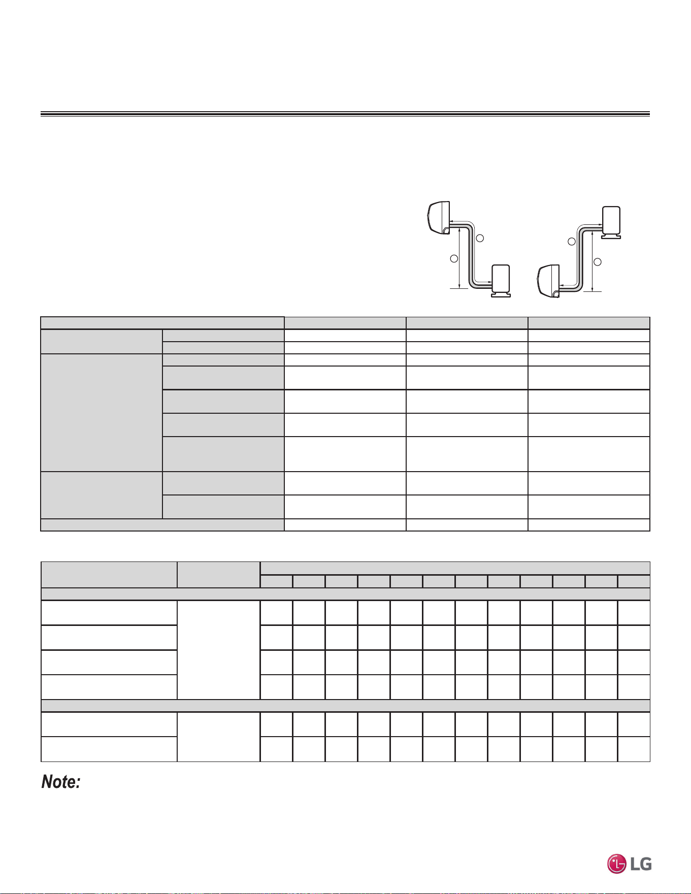
68 | APPLICATION GUIDELINES
Single Zone Mega Wall Mounted Engineering Manual
'XHWRRXUSROLF\RIFRQWLQXRXVSURGXFWLQQRYDWLRQVRPHVSHFL¿FDWLRQVPD\FKDQJHZLWKRXWQRWL¿FDWLRQ
©
/*(OHFWURQLFV86$,QF(QJOHZRRG&OLIIV1-$OOULJKWVUHVHUYHG³/*´LVDUHJLVWHUHGWUDGHPDUNRI/*&RUS
REFRIGERANT PIPING DESIGN
'HVLJQ*XLGHOLQH6XPPDU\
Table 40: Single-Zone Mega and Mega 115V Wall Mount Refrigerant Piping System Limitations.
Figure 39: Mega and Mega 115V System Layout.
Max Length = A
Max Elevation = B
Unit = Feet
Outdoor unit
Indoor unit
A
B
Outdoor unit
Indoor unit
A
B
Device Connection Limitations
Single-zone systems consist of one outdoor unit and one indoor unit. One of
the most critical elements of a single zone system is the refrigerant piping. The
table below lists pipe length limits that must be followed in the design of a Single
Zone Mega or Mega 115V refrigerant pipe system. Refer to the figure at right for
maximum length and elevation of piping.
Model Numbers LS090HEV2, LS120HEV2 LS180HEV2, LS240HEV2 LS090HXV, LSU120HXV
Pipe Sizes
Vapor
3/8 inches 1/2 inches 3/8 inches
Liquid
1/4 inches 1/4 inches 1/4 inches
Pipe Length
(ELF = Equivalent Length of
pipe in Feet)
Standard Piping Length
24.6 24.6 24.6
Piping Length with No
Additional Refrigerant
24.6 24.6 24.6
Longest total equivalent
piping length
49.2 65.6 49.2
Shortest total equivalent
piping length
9.8 9.8 6.6
Distance between fittings
and indoor units or outdoor
units
LQFKHV LQFKHV LQFKHV
Elevation
(All Elevation Limitations are
Measured in Actual Feet)
If outdoor unit is above
indoor unit
23 feet 32.8 feet 23 feet
If outdoor unit is below
indoor unit
23 feet 32.8 feet 23 feet
Additional Refrigerant Needed (oz/ft)
0.22 0.26 0.22
Model Numbers
Refrigerant Piping Length (ft.)
16.4 24.6 32.8 41.0 49.2 65.6 82.0 98.4 114.8 131.2 147.6 164.0
Mega
LS090HEV2
(LSN090HEV2 / LSU090HEV2)
Additional
Refrigerant
Charge (oz.)
0 0 1.8 3.6 5.4 - - - - - - -
LS120HEV2
(LSN120HEV2 / LSU120HEV2)
001.83.65.4-------
LS180HEV2
(LSN180HEV2 / LSU180HEV2)
002.14.36.410.7------
LS240HEV2
(LSN240HEV2 / LSU240HEV2)
002.14.36.410.7------
Mega 115V
LS090HXV
(LSN090HXV / LSU090HXV)
Additional
Refrigerant
Charge (oz.)
001.83.65.4-------
LS120HXV
(LSN090HXV / LSU090HXV)
001.83.65.4-------
Table 41: Single Zone Mega and Mega 115V Piping System Additional Refrigerant Charge.
• Capacity is based on standard length.
• Equivalent Pipe Length = Actual Pipe Length + Number of Bends x 0.3.
• Additional Refrigerant Charge Calculation : X (g) = [ (Refrigerant Pipe Length) - (No Charge Pipe Length) ] × (Additional Refrigerant).
• There is no need to add refrigerant if equivalent pipe is less than the “piping length with no additional refrigerant” in the table above.

LG Electronics, U.S.A., Inc.
Commercial Air Conditioning Division
4300 North Point Parkway
Alpharetta, Georgia 30022
www.lghvac.com
EM-SZ_Mega_Mega115V_HEV2_HXV__05_19
Supersedes: EM-SZ_Mega_Mega115V-3-16 EM-
SZ_Mega_Mega115V-4-15
EM-SZ_Mega_Mega115V-10-14
20001747 ISO 9001: 2008
LG ELECTRONICS INC.