• Do not cool excessively indoors. This may be harmful for your health and may consume more
electricity.
• Block sunlight with blinds or curtains while you are operating the air conditioner.
• Keep doors or windows closed tightly while you are operating the air conditioner.
• Adjust the direction of the air flow vertically or horizontally to circulate indoor air.
• Speed up the fan to cool indoor air quickly.
• Open windows regularly for ventilation as the indoor air quality may deteriorate if the air
conditioner is used for many hours.
• Clean the air filter once every 2 weeks. Dust and impurities collected in the air filter may block the
air flow or weaken the cooling / dehumidifying functions.
For your records
Staple your receipt to this page in case you need it to prove the date of purchase or for warranty
purposes. Write the model number and the serial number here:
Model number :
Serial number :
You can find them on a label on the side of each unit.
Dealer’s name :
Date of purchase :
Here are some tips that will help you minimize power consumption when you use your air condi-
tioner.
TIPS FOR SAVING ENERGY
• Thickness of copper pipes used are as shown “Flaring work” Table.
- Never use copper pipes thinner than that in the table even when it is available on the market
• Do not use copper pipes having a collapsed.
- Otherwise, the expansion valve or capillary tube may become blocked with contaminants.
• For R410A model, use piping, flare nut and tools which is specified for R410A refrigerant.
- Using of (R22) piping, flare nut and tools may cause abnormally high pressure in the refrigerant
cycle (piping), and possibly result in explosion and injury.
• It is desirable that the amount of residual oil less than 40 mg/10m.
• Do not turn on the breaker or power under condition that front panel, cabinet, top cover, and control
box cover are removed or opened.
- Otherwise, it may cause fire, electric shock, explosion or death.
• If the air conditioner is installed in a small room, measures must be taken to prevent the refrigerant
concentration from exceeding the safety limit when the refrigerant leaks.
- Consult the dealer regarding the appropriate measures to prevent the safety limit from being
exceeded. Should the refrigerant leak and cause the safety limit to be exceeded, hazards due to
lack of oxygen in the room could result.
• Use a vacuum pump or inert (nitrogen) gas when doing leakage test or air purge. Do not compress
air or oxygen and do not use flammable gases.
- Otherwise, it may cause fire or explosion. There is the risk of death, injury, fire or explosion.
Operation
• Do not share the outlet with other appliances.
- It will cause an electric shock or a fire due to heat generation.
• Do not use the damaged power cord.
- Otherwise, it may cause a fire or electrical shock.
• Do not modify or extend the power cable.
- Scratches or peeling insulation on the power cables may result in fire or electric shock, and should
be replaced.
• Take care so that the power cord may not be pulled during operation.
- Otherwise, it may cause a fire or electrical shock.
• Unplug the unit if strange sounds, smell, or smoke comes from it.
- Otherwise, it may cause electrical shock or a fire.
• Keep the flames away.
- Otherwise, it may cause a fire.
• Take the power plug out if necessary, holding the head of the plug and do not touch it with wet
hands.
- Otherwise, it may cause a fire or electrical shock.
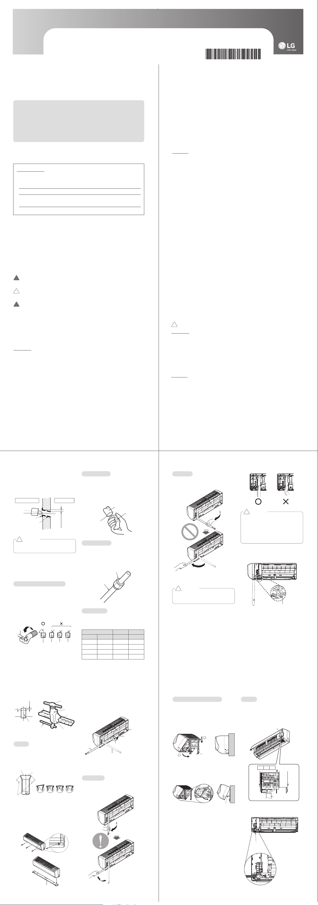
Select the best Location
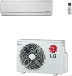
Indoor unit
- There should not be any heat or steam near
the unit.
- Select a place where there are no obstacles
around the unit.
- Make sure that condensation drainage can
be conveniently routed away.
- Do not install near a doorway.
- Ensure that the gap between a wall and the
left (or right) of the unit is more than 4in. The
unit should be installed as high as possible
on the wall, allowing a minimum of 8in from
ceiling.
- Use a metal detector to locate studs to pre-
vent unnecessary damage to the wall.
* Recommended height 6.5ft from the floor.
* Features may change according to the type
of model.
Outdoor unit
- If an awning is built over the unit to prevent
direct sunlight or rain exposure, make sure
that heat radiation from the condenser is not
restricted.
- Ensure that the space around the back side
and other sides is more than 12in. The space
in front of the unit should be more than 28in.
- Do not place animals and plants in the path
of the warm air.
- Take the weight of the air conditioner into
account and select a place where noise and
vibration are minimum.
- Select a place where the warm air and noise
from the air conditioner do not disturb neigh-
bors.
More than 8in
More than
4in
More than
4in
(Unit : in)
More than
12in
More than
12in
Sunroof
Fence or
obstacles
More than
28in
More than
24in
(Unit : in)
INSTALLATION
NOTE
!
Remove obstructions to prevent blockage
of airflow path.
IMPORTANT SAFETY INSTRUCTIONS
READ ALL INSTRUCTIONS BEFORE USING THE APPLIANCE.
Always comply with the following precautions to avoid dangerous situations and to ensure peak
performance of your product.
WARNING
It can result in serious injury or death when the directions are ignored.
CAUTION
It can result in minor injury or product damage when the directions are ignored.
WARNING
• Installation or repairs made by unqualified persons can result in hazards to you and others.
• Air conditioner Shall be installed in accordance with national wiring regulations.
• If the supply cord is damaged, it must be replaced by the manufacturer, its service agent or
similarly qualified persons in order to avoid a hazard.
• The information contained in the manual is intended for use by a qualified service technician familiar
with safety procedures and equipped with the proper tools and test instruments.
• Failure to read and follow all instructions in this manual can result in equipment malfunction, proper-
ty damage, personal injury and/or death.
Installation
• Always perform grounding.
- Otherwise, it may cause electrical shock.
• Don’t use a power cord, a plug or a loose socket which is damaged.
- Otherwise, it may cause a fire or electrical shock.
• For installation of the product, always contact the service center or a professional installation
agency.
- Otherwise, it may cause a fire, electrical shock, explosion or injury.
• Securely attach the electrical part cover to the indoor unit and the service panel to the outdoor unit.
- If the electrical part cover of the indoor unit and the service panel of the outdoor unit are not
attached securely, it could result in a fire or electric shock due to dust, water, etc.
• Always install an earth leakage circuit breaker and a dedicated switching board.
- No installation may cause a fire and electrical shock.
• Do not keep or use flammable gases or combustibles near the air conditioner.
- Otherwise, it may cause a fire or the failure of product.
• Ensure that an installation frame of the outdoor unit is not damaged due to use for a long time.
- It may cause injury or an accident.
• Do not disassemble or repair the product randomly.
- It will cause a fire or electrical shock.
• Do not install the product at a place that there is concern of falling down.
- Otherwise, it may result in personal injury.
• Use caution when unpacking and installing.
- Sharp edges may cause injury.
!
!
!
• Do not use the power cord near the heating tools.
- Otherwise, it may cause a fire and electrical shock.
• Do not open the suction inlet of the indoor/outdoor unit during operation.
- Otherwise, it may electrical shock and failure.
• Do not allow water to run into electrical parts.
- Otherwise, it may cause the failure of machine or electrical shock.
• Hold the plug by the head when taking it out.
- It may cause electric shock and damage.
• Never touch the metal parts of the unit when removing the filter.
- They are sharp and may cause injury.
• Do not step on the indoor/outdoor unit and do not put anything on it.
- It may cause an injury through dropping of the unit or falling down.
• Do not place a heavy object on the power cord.
- Otherwise, it may cause a fire or electrical shock.
• When the product is submerged into water, always contact the service center.
- Otherwise, it may cause a fire or electrical shock.
• Take care so that children may not step on the outdoor unit.
- Otherwise, children may be seriously injured due to falling down.
CAUTION
Installation
• Install the drain hose to ensure that drain can be securely done.
- Otherwise, it may cause water leakage.
• Install the product so that the noise or hot wind from the outdoor unit may not cause any damage to
the neighbors.
- Otherwise, it may cause dispute with the neighbors.
• Always inspect gas leakage after the installation and repair of product.
- Otherwise, it may cause the failure of product.
• Keep level parallel in installing the product.
- Otherwise, it may cause vibration or water leakage.
Operation
• Avoid excessive cooling and perform ventilation sometimes.
- Otherwise, it may do harm to your health.
• Use a soft cloth to clean. Do not use wax, thinner, or a strong detergent.
- The appearance of the air conditioner may deteriorate, change color, or develop surface flaws.
• Do not use an appliance for special purposes such as preserving animals vegetables, precision
machine, or art articles.
- Otherwise, it may damage your properties.
• Do not place obstacles around the flow inlet or outlet.
- Otherwise, it may cause the failure of appliance or an accident.
* Features may change according to the type of model.
!
INSTALLATION TOOLS
INSTALLATION PARTS
Name
Quantity Shape
Installation plate
1 EA
Type "A" screw
5 EA
Type "B" screw
Type "B" screw
2 EA
Type "C" screw
2 EA
Type "D" screw
2 EA
Bracket
1 EA
Remote control
holder
1 EA
h The features may change according to the type of model.
Screws for fixing panels are attached to decoration panel.
Figure FigureName
Screw driver
Electric drill
Measuring tape, Knife
Hole core drill
Spanner
Torque wrench
Multi-meter
Hexagonal wrench
Ammeter
Gas-leak detector
Thermometer,
Level
Flaring tool set
Name
1 Where there are obstacles on both suction
and discharge sides (discharge side obsta-
cle is lower than the outdoor unit).
Outdoor Unit Service Access and
Allowable Clearances
Minimum
27-19/32 (700)
Minimum
11-13/16 (300)
Unit : inch (mm)
Minimum
11-13/16 (300)
78-3/4 (2000)
23-19/32 (600)
Minimum 27-19/32 (700)
Unit : inch (mm)
2 Where there are obstacles above, and on
both suction and discharge sides (dis-
charge side obstacle is lower than the out-
door unit).
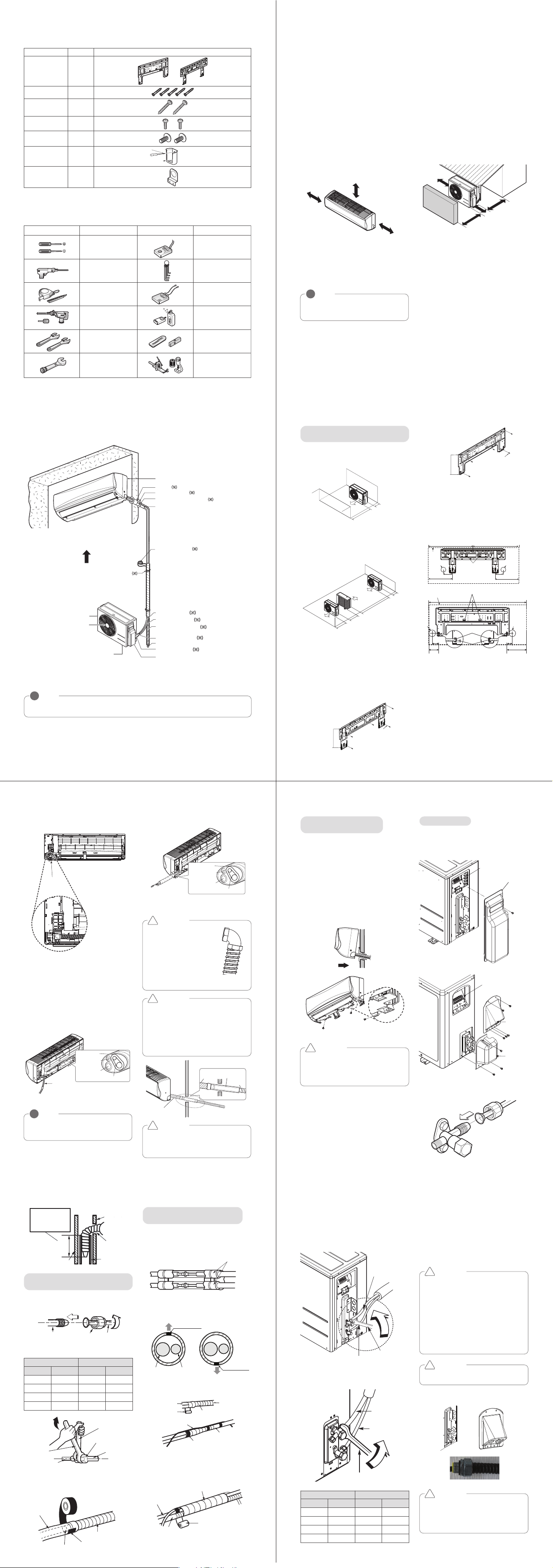
Fixing Installation Plate
The wall you select should be strong and solid
enough to prevent vibration
1 Mount the installation plate on the wall
with type "A" screws. If mounting the unit
on a concrete wall, use anchor bolts.
-
Mount the installation plate horizontally by
aligning the centerline using Horizontal meter.
Both Installation Plates can be used for
this model.
2
Measure the wall and mark the centerline. It is
also important to use caution concerning the
location of the installation plate. Routing of the
wiring to power outlets is through the walls
typically. Drilling the hole through the wall for
piping connections must be done safely.
Both Installation Plates can be used for
this model.
Installation Plate
Chassis
Hook
Type "A" Screws
Installation Plate
Chassis
Hook
Type "A" Screws
Ø2-9/16
(65)
Ø2-9/16
Ø2-9/16
(65)
(65)
Ø2-9/16
(65)
Right
rear
piping
Left
rear
piping
Installation Plate
Place a level on raised tab
Unit Outline
8-3/32
(207)
4-3/32
(105)
Unit : inch (mm)
18-1/8(460) 22-13/32(570)
Measuring Tape
Hanger
Measuring Tape
2-11/16(69)
2-3/16(156)
Unit
Outline
Left Rear
Piping
Right Rear
Piping
Place a level on raised tab
Unit : inch (mm)
Installation plate
Ø2-9/16(65)
Ø2-9/16(65)
7-1/4(184)
8-11/16(220)
6-5/32(156)
12-3/32(307)
18-1/8(460) 22-11/32(567)
INSTALLATION MAP
Vinyl tape (Wide)
• Apply after carrying out a
drainage test.
• To carry out the drainage
test, remove the air filters
and pour water into the heat
exchanger.
Saddle
Gas side piping
Liquid side piping
Additional drain pipe
Vinyl tape (Narrow)
Drain Hose
Base Plate
Air Outlet
Air Inlet
Connecting cable
Tubing Cover
Sleeve
Bushing-Sleeve
Putty(Gum Type Sealant)
Bend the pipe as closely
on the wall as possible,
but be careful that it
doesn't break.
Installation plate
Taping Direction
NOTE
!
• You should purchase the installation parts.
* The feature can be changed according to the type of model.
Pipe
Reamer
Point down
Flare nut
Copper tube
1 Completely remove all burrs from the cut
cross section of pipe/tube.
2 While removing burrs put the end of the
copper tube/pipe in a downward direction
while removing burrs location is also
changed in order to avoid dropping burrs
into the tubing.
- Remove flare nuts attached to indoor and
outdoor units, then put them on the
pipe/tube which have completed its burr
removal.
(not possible to put them on after finishing
flare work)
Flaring work
1 Firmly hold copper pipe in a bar with the
dimension shown in table below.
2 Carry out flaring work with the flaring tool.
Burrs removal
Putting nut on
Drill a Hole in the Wall
- Drill the piping hole with a ø65mm hole core
drill. Drill the piping hole at either the right or
the left with the hole slightly slanted to the
outdoor side.
Flaring Work
Main cause for gas leakage is due to defect of
flaring work. Carry out correct flaring work in
the following procedure.
1 Use the piping kit accessory or the pipes
purchased locally.
2 Measure the distance between the indoor
and the outdoor unit.
3 Cut the pipes a little longer than measured
distance.
4 Cut the cable 1.5m (4.9 ft) longer than the
pipe length.
CAUTION
Use the sleeve to prevent damage for
tube assembly.
!
5-7mm
(3/16"~5/16")
Indoor
WALL
Outdoor
Bushing
Sleeve
Copper
pipe
90°
Slanted Uneven Rough
Cut the pipes and the cable
Outside diameter A
Thickness
mm inch mm mm
Ø6.35 1/4 1.1~1.3 0.7
Ø9.52 3/8 1.5~1.7 0.8
Ø12.7 1/2 1.6~1.8 0.8
Ø15.88 5/8 1.6~1.8 1.0
- Following bending case from right to left
directly may cause damage to the tubing.
* Features may change according to the type
of model.
CAUTION
Installation Information. For right piping.
Follow the instruction above.
!
Bad case
Type “D” Screw
- Before bending the tubing, set the conduit
like picture below by using the bracket and
black screws from accessory kit.
CAUTION
• Secure the pipe by using the tubing
cover.
• Do not strongly press the refrigerant
pipes onto the bottom frame.
• Do not strongly press the refrigerant
pipes on the front grille, either.
!
Indoor Outdoor
Indoor Unit
Drain hose
Indoor Unit
Drain hose
Insulation
(More than 100~300mm
length and 7mm thickness)
Extension
drain hose
CAUTION
If the extension drain hose is routed
inside the room, insulate the hose with an
insulation material* so that dripping from
sweating (condensation) could not dam-
age furniture or floors.
• Foamed polyethylene or equivalent is
recommended.
!
CAUTION
Must use the elbow type
(L-Type) conduit
Method:
1. Disassemble bracket
(from indoor unit)
2. Assemble it with conduit
3. Reassemble it with indoor
unit.
!
CAUTION
Insert the drain hose more than 1-15/16”
(50mm) so it won’t be pulled out of the
drain pipe.
!
<Left side piping>
Drain hose
Connecting pipe
Connecting
cable
Tape
Drain hose
3 Tape the tubing pipe, drain hose and the
connection cable. Be sure that the drain
hose is located at the lowest side of the
bundle. Locating at the upper side can
cause overflow from the drain pan through
the inside of the unit.
<Right side piping>
View
NOTE
!
Insert the drain hose at left side when
you use left side piping type.
* Features may change according to the type
of model.
<Right side piping>
Connecting pipe
Connecting
cable
Tape
Drain hose
Finishing the indoor unit
installation
1 Mount the tubing holder in the original
positon.
2 Ensure that the hooks are properly seated
on the installation plate by moving it left
and right.
3 Press the lower left and right sides of the
unit against the installation plate until the
hooks engage into their slots (clicking
sound).
4 Finish the assembly by screwing the unit
to the installation plate by using two pieces
of type "C" screws. And assemble a chas-
sis cover.
Type 'C' screw
CAUTION
• Before finishing installation of the indoor
unit, seal the hole of a wall except the
pipe’s ways to prevent condensate from
inflow of outdoor air.
!
Connecting the Piping
- Remove the tubing cover from the unit by
loosening the screw.
<18k>
<24k>
- Align the center of the pipings and sufficient-
ly tighten the flare nut by hand.
Terminal Block
Tubing
Cover
Tubing
Cover
Cover
control
Terminal Block
Outdoor unit
Bar
Copper pipe
Clamp handle
Red arrow mark
Cone
Yoke
Handle
Bar
"A"
Inclined
Inside is shiny without scratches
Smooth all round
Even length
all round
Surface
damaged
Cracked Uneven
thickness
= Improper flaring =
1 Compare the flared work with the figures
given below.
2 If a flared section is defective, cut it off
and do flaring work again.
Connecting the Piping
1 Pull the screw caps at the bottom of the
indoor unit
2 Remove the chassis cover from the unit by
loosing 3 screws
Check
Chassis cover
3 Pull back the tubing holder.
4 Remove the pipe port cover and position
the piping.
* Features may change according to the type
of model.
- Press the tubing cover and slowly unfold the
tubing to downward. And then bend to the
left side slowly.
Right
Back side view
Tubing holder
Backwards
Left
Pipe Port
Good case
Installation of Indoor Unit
1 Raise the cover of terminal block.
2 Insert the connecting cable through the
bottom side of indoor unit and connect the
cable. (You can see detail contents in
‘Connecting the cables’ section.)
<Left side piping>
1 Hook the indoor unit onto the upper por-
tion of the installation plate.( engage the
three hooks at the top of the indoor unit
with the upper edge of the installation
plate) Ensure that the hooks are properly
seated on the installation plate by moving
it left and right
2 Unlock the tubing holder from the chassis
and mount between the chassis and instal-
lation plate in order to separate the bottom
side of the indoor unit from the wall.
* Features may change according to the type
of model.
1
2
Installation plate
Tubing Holder
Control Cover
1(L1) 2(L2)
1(L1) 2(L2)
3
Power connecting cable
Piping
View
3 When needed to extend the drain hose of
indoor unit, assembly the drain pipe as
shown on the drawing
Wrench
Indoor unit tubing
Open-end wrench
(fixed)
Connection
pipe
Flare nut
Vinyl tape(narrow)
Adhesive
Drain pipe
Indoor unit drain hose
1 Align the center of the pipes and sufficient-
ly tighten the flare nut by hand
2 Tighten the flare nut with a wrench
Indoor unit tubing Flare nut Pipes
Outside Diameter Torque
mm inch kgf·cm N·m
Ø6.35 1/4 180~250 17.6~24.5
Ø9.52 3/8 340~420 33.3~41.2
Ø12.7 1/2 550~660 53.9~64.7
Ø15.88 5/8 630~820 61.7~80.4
Connecting the installation pipe
and drain hose to the indoor unit.
3 Bundle the piping and drain hose together
by wrapping them with vinyl tape sufficient
enough to cover where they fit into the
rear piping housing section.
Vinyl tape(narrow)
Connection pipe
Connecting cable
Vinyl tape (wide)
Wrap with vinyl tape
Indoor unit pipe
Pipe
Wrap with vinyl tape
Drain hose
Pipe
Vinyl tape(wide)
Wrap the insulation material
around the connecting portion.
1 Overlap the connection pipe insulation
material and the indoor unit pipe insulation
material. Bind them together with vinyl
tape so that there may be no gap.
2 Set the tubing cutting line upward. Wrap
the area which accommodates the rear
piping housing section with vinyl tape.
Gas Pipe
Liquid Pipe
Cutting Line
Cutting Line
Good Case Bad Case
Insulation material
* Tubing cutting line have to be upward.
Insert the drain
hose to this depth
so it won’t be pulled
out of drain pipe.
1-15/16” (50mm)
or more
Drain Hose
Inner wall
Vinyl chloride
drain pipe
(VP-30)
Outer wall
Connecting the Cables
Connect the cable to the indoor unit by con-
necting the wires to the terminals on the con-
trol board individually according to the outdoor
unit connection. (Ensure that the color of the
wires of the outdoor unit and the terminal No.
are the same as those of the indoor unit.)
CAUTION
- The circuit diagram is a subject to
change without notice.
- The earth wire should be longer than the
common wires.
- When installing, refer to the circuit dia-
gram on the chassis cover.
- Connect the wires firmly so that they
may not be pulled out easily.
- Connect the wires according to color
codes, referring to the wiring diagram.
!
CAUTION
The power cord connected to the outdoor
unit should be complied with the
following specifications (UL recognized or
CSA certified).
!
CAUTION
- Assemble it with conduit.
!
- Finally, tighten the flare nut with torque
wrench until the wrench clicks.
When tightening the flare nut with torque
wrench, ensure the direction for tightening
follows the arrow on the wrench.
<18k>
Outside Diameter Torque
mm inch kgf·cm N·m
Ø6.35 1/4 180~250 17.6~24.5
Ø9.52 3/8 340~420 33.3~41.2
Ø12.7 1/2 550~660 53.9~64.7
Ø15.88 5/8 630~820 61.7~80.4
<24k>
<18k> <24k>
Torque wrench
Gas side piping
(Bigger diameter)
Liquid side piping
(Smaller diameter)
Outdoor unit Outdoor unit Outdoor unit
Outdoor unit
Torque wrench
Liquid side piping
(Smaller diameter)
Gas side piping
(Bigger diameter)
1 2 3
54 6 7
INSTALLATION MANUAL AIR CONDITIONER
TYPE : WALL MOUNTED
P/No : MFL67647124
ENGLISH
MFL67647124(영영) 2016. 7. 15. 영영 1:26 Page 1
• Do not cool excessively indoors. This may be harmful for your health and may consume more
electricity.
• Block sunlight with blinds or curtains while you are operating the air conditioner.
• Keep doors or windows closed tightly while you are operating the air conditioner.
• Adjust the direction of the air flow vertically or horizontally to circulate indoor air.
• Speed up the fan to cool indoor air quickly.
• Open windows regularly for ventilation as the indoor air quality may deteriorate if the air
conditioner is used for many hours.
• Clean the air filter once every 2 weeks. Dust and impurities collected in the air filter may block the
air flow or weaken the cooling / dehumidifying functions.
For your records
Staple your receipt to this page in case you need it to prove the date of purchase or for warranty
purposes. Write the model number and the serial number here:
Model number :
Serial number :
You can find them on a label on the side of each unit.
Dealer’s name :
Date of purchase :
Here are some tips that will help you minimize power consumption when you use your air condi-
tioner.
TIPS FOR SAVING ENERGY
• Thickness of copper pipes used are as shown “Flaring work” Table.
- Never use copper pipes thinner than that in the table even when it is available on the market
• Do not use copper pipes having a collapsed.
- Otherwise, the expansion valve or capillary tube may become blocked with contaminants.
• For R410A model, use piping, flare nut and tools which is specified for R410A refrigerant.
- Using of (R22) piping, flare nut and tools may cause abnormally high pressure in the refrigerant
cycle (piping), and possibly result in explosion and injury.
• It is desirable that the amount of residual oil less than 40 mg/10m.
• Do not turn on the breaker or power under condition that front panel, cabinet, top cover, and control
box cover are removed or opened.
- Otherwise, it may cause fire, electric shock, explosion or death.
• If the air conditioner is installed in a small room, measures must be taken to prevent the refrigerant
concentration from exceeding the safety limit when the refrigerant leaks.
- Consult the dealer regarding the appropriate measures to prevent the safety limit from being
exceeded. Should the refrigerant leak and cause the safety limit to be exceeded, hazards due to
lack of oxygen in the room could result.
• Use a vacuum pump or inert (nitrogen) gas when doing leakage test or air purge. Do not compress
air or oxygen and do not use flammable gases.
- Otherwise, it may cause fire or explosion. There is the risk of death, injury, fire or explosion.
Operation
• Do not share the outlet with other appliances.
- It will cause an electric shock or a fire due to heat generation.
• Do not use the damaged power cord.
- Otherwise, it may cause a fire or electrical shock.
• Do not modify or extend the power cable.
- Scratches or peeling insulation on the power cables may result in fire or electric shock, and should
be replaced.
• Take care so that the power cord may not be pulled during operation.
- Otherwise, it may cause a fire or electrical shock.
• Unplug the unit if strange sounds, smell, or smoke comes from it.
- Otherwise, it may cause electrical shock or a fire.
• Keep the flames away.
- Otherwise, it may cause a fire.
• Take the power plug out if necessary, holding the head of the plug and do not touch it with wet
hands.
- Otherwise, it may cause a fire or electrical shock.
Select the best Location
Indoor unit
- There should not be any heat or steam near
the unit.
- Select a place where there are no obstacles
around the unit.
- Make sure that condensation drainage can
be conveniently routed away.
- Do not install near a doorway.
- Ensure that the gap between a wall and the
left (or right) of the unit is more than 4in. The
unit should be installed as high as possible
on the wall, allowing a minimum of 8in from
ceiling.
- Use a metal detector to locate studs to pre-
vent unnecessary damage to the wall.
* Recommended height 6.5ft from the floor.
* Features may change according to the type
of model.
Outdoor unit
- If an awning is built over the unit to prevent
direct sunlight or rain exposure, make sure
that heat radiation from the condenser is not
restricted.
- Ensure that the space around the back side
and other sides is more than 12in. The space
in front of the unit should be more than 28in.
- Do not place animals and plants in the path
of the warm air.
- Take the weight of the air conditioner into
account and select a place where noise and
vibration are minimum.
- Select a place where the warm air and noise
from the air conditioner do not disturb neigh-
bors.
More than 8in
More than
4in
More than
4in
(Unit : in)
More than
12in
More than
12in
Sunroof
Fence or
obstacles
More than
28in
More than
24in
(Unit : in)
INSTALLATION
NOTE
!
Remove obstructions to prevent blockage
of airflow path.
IMPORTANT SAFETY INSTRUCTIONS
READ ALL INSTRUCTIONS BEFORE USING THE APPLIANCE.
Always comply with the following precautions to avoid dangerous situations and to ensure peak
performance of your product.
WARNING
It can result in serious injury or death when the directions are ignored.
CAUTION
It can result in minor injury or product damage when the directions are ignored.
WARNING
• Installation or repairs made by unqualified persons can result in hazards to you and others.
• Air conditioner Shall be installed in accordance with national wiring regulations.
• If the supply cord is damaged, it must be replaced by the manufacturer, its service agent or
similarly qualified persons in order to avoid a hazard.
• The information contained in the manual is intended for use by a qualified service technician familiar
with safety procedures and equipped with the proper tools and test instruments.
• Failure to read and follow all instructions in this manual can result in equipment malfunction, proper-
ty damage, personal injury and/or death.
Installation
• Always perform grounding.
- Otherwise, it may cause electrical shock.
• Don’t use a power cord, a plug or a loose socket which is damaged.
- Otherwise, it may cause a fire or electrical shock.
• For installation of the product, always contact the service center or a professional installation
agency.
- Otherwise, it may cause a fire, electrical shock, explosion or injury.
• Securely attach the electrical part cover to the indoor unit and the service panel to the outdoor unit.
- If the electrical part cover of the indoor unit and the service panel of the outdoor unit are not
attached securely, it could result in a fire or electric shock due to dust, water, etc.
• Always install an earth leakage circuit breaker and a dedicated switching board.
- No installation may cause a fire and electrical shock.
• Do not keep or use flammable gases or combustibles near the air conditioner.
- Otherwise, it may cause a fire or the failure of product.
• Ensure that an installation frame of the outdoor unit is not damaged due to use for a long time.
- It may cause injury or an accident.
• Do not disassemble or repair the product randomly.
- It will cause a fire or electrical shock.
• Do not install the product at a place that there is concern of falling down.
- Otherwise, it may result in personal injury.
• Use caution when unpacking and installing.
- Sharp edges may cause injury.
!
!
!
• Do not use the power cord near the heating tools.
- Otherwise, it may cause a fire and electrical shock.
• Do not open the suction inlet of the indoor/outdoor unit during operation.
- Otherwise, it may electrical shock and failure.
• Do not allow water to run into electrical parts.
- Otherwise, it may cause the failure of machine or electrical shock.
• Hold the plug by the head when taking it out.
- It may cause electric shock and damage.
• Never touch the metal parts of the unit when removing the filter.
- They are sharp and may cause injury.
• Do not step on the indoor/outdoor unit and do not put anything on it.
- It may cause an injury through dropping of the unit or falling down.
• Do not place a heavy object on the power cord.
- Otherwise, it may cause a fire or electrical shock.
• When the product is submerged into water, always contact the service center.
- Otherwise, it may cause a fire or electrical shock.
• Take care so that children may not step on the outdoor unit.
- Otherwise, children may be seriously injured due to falling down.
CAUTION
Installation
• Install the drain hose to ensure that drain can be securely done.
- Otherwise, it may cause water leakage.
• Install the product so that the noise or hot wind from the outdoor unit may not cause any damage to
the neighbors.
- Otherwise, it may cause dispute with the neighbors.
• Always inspect gas leakage after the installation and repair of product.
- Otherwise, it may cause the failure of product.
• Keep level parallel in installing the product.
- Otherwise, it may cause vibration or water leakage.
Operation
• Avoid excessive cooling and perform ventilation sometimes.
- Otherwise, it may do harm to your health.
• Use a soft cloth to clean. Do not use wax, thinner, or a strong detergent.
- The appearance of the air conditioner may deteriorate, change color, or develop surface flaws.
• Do not use an appliance for special purposes such as preserving animals vegetables, precision
machine, or art articles.
- Otherwise, it may damage your properties.
• Do not place obstacles around the flow inlet or outlet.
- Otherwise, it may cause the failure of appliance or an accident.
* Features may change according to the type of model.
!
INSTALLATION TOOLS
INSTALLATION PARTS
Name
Quantity Shape
Installation plate
1 EA
Type "A" screw
5 EA
Type "B" screw
Type "B" screw
2 EA
Type "C" screw
2 EA
Type "D" screw
2 EA
Bracket
1 EA
Remote control
holder
1 EA
h The features may change according to the type of model.
Screws for fixing panels are attached to decoration panel.
Figure FigureName
Screw driver
Electric drill
Measuring tape, Knife
Hole core drill
Spanner
Torque wrench
Multi-meter
Hexagonal wrench
Ammeter
Gas-leak detector
Thermometer,
Level
Flaring tool set
Name
1 Where there are obstacles on both suction
and discharge sides (discharge side obsta-
cle is lower than the outdoor unit).
Outdoor Unit Service Access and
Allowable Clearances
Minimum
27-19/32 (700)
Minimum
11-13/16 (300)
Unit : inch (mm)
Minimum
11-13/16 (300)
78-3/4 (2000)
23-19/32 (600)
Minimum 27-19/32 (700)
Unit : inch (mm)
2 Where there are obstacles above, and on
both suction and discharge sides (dis-
charge side obstacle is lower than the out-
door unit).
Fixing Installation Plate
The wall you select should be strong and solid
enough to prevent vibration
1 Mount the installation plate on the wall
with type "A" screws. If mounting the unit
on a concrete wall, use anchor bolts.
-
Mount the installation plate horizontally by
aligning the centerline using Horizontal meter.
Both Installation Plates can be used for
this model.
2
Measure the wall and mark the centerline. It is
also important to use caution concerning the
location of the installation plate. Routing of the
wiring to power outlets is through the walls
typically. Drilling the hole through the wall for
piping connections must be done safely.
Both Installation Plates can be used for
this model.
Installation Plate
Chassis
Hook
Type "A" Screws
Installation Plate
Chassis
Hook
Type "A" Screws
Ø2-9/16
(65)
Ø2-9/16
Ø2-9/16
(65)
(65)
Ø2-9/16
(65)
Right
rear
piping
Left
rear
piping
Installation Plate
Place a level on raised tab
Unit Outline
8-3/32
(207)
4-3/32
(105)
Unit : inch (mm)
18-1/8(460) 22-13/32(570)
Measuring Tape
Hanger
Measuring Tape
2-11/16(69)
2-3/16(156)
Unit
Outline
Left Rear
Piping
Right Rear
Piping
Place a level on raised tab
Unit : inch (mm)
Installation plate
Ø2-9/16(65)
Ø2-9/16(65)
7-1/4(184)
8-11/16(220)
6-5/32(156)
12-3/32(307)
18-1/8(460) 22-11/32(567)
INSTALLATION MAP
Vinyl tape (Wide)
• Apply after carrying out a
drainage test.
• To carry out the drainage
test, remove the air filters
and pour water into the heat
exchanger.
Saddle
Gas side piping
Liquid side piping
Additional drain pipe
Vinyl tape (Narrow)
Drain Hose
Base Plate
Air Outlet
Air Inlet
Connecting cable
Tubing Cover
Sleeve
Bushing-Sleeve
Putty(Gum Type Sealant)
Bend the pipe as closely
on the wall as possible,
but be careful that it
doesn't break.
Installation plate
Taping Direction
NOTE
!
• You should purchase the installation parts.
* The feature can be changed according to the type of model.
Pipe
Reamer
Point down
Flare nut
Copper tube
1 Completely remove all burrs from the cut
cross section of pipe/tube.
2 While removing burrs put the end of the
copper tube/pipe in a downward direction
while removing burrs location is also
changed in order to avoid dropping burrs
into the tubing.
- Remove flare nuts attached to indoor and
outdoor units, then put them on the
pipe/tube which have completed its burr
removal.
(not possible to put them on after finishing
flare work)
Flaring work
1 Firmly hold copper pipe in a bar with the
dimension shown in table below.
2 Carry out flaring work with the flaring tool.
Burrs removal
Putting nut on
Drill a Hole in the Wall
- Drill the piping hole with a ø65mm hole core
drill. Drill the piping hole at either the right or
the left with the hole slightly slanted to the
outdoor side.
Flaring Work
Main cause for gas leakage is due to defect of
flaring work. Carry out correct flaring work in
the following procedure.
1 Use the piping kit accessory or the pipes
purchased locally.
2 Measure the distance between the indoor
and the outdoor unit.
3 Cut the pipes a little longer than measured
distance.
4 Cut the cable 1.5m (4.9 ft) longer than the
pipe length.
CAUTION
Use the sleeve to prevent damage for
tube assembly.
!
5-7mm
(3/16"~5/16")
Indoor
WALL
Outdoor
Bushing
Sleeve
Copper
pipe
90°
Slanted Uneven Rough
Cut the pipes and the cable
Outside diameter A
Thickness
mm inch mm mm
Ø6.35 1/4 1.1~1.3 0.7
Ø9.52 3/8 1.5~1.7 0.8
Ø12.7 1/2 1.6~1.8 0.8
Ø15.88 5/8 1.6~1.8 1.0
- Following bending case from right to left
directly may cause damage to the tubing.
* Features may change according to the type
of model.
CAUTION
Installation Information. For right piping.
Follow the instruction above.
!
Bad case
Type “D” Screw
- Before bending the tubing, set the conduit
like picture below by using the bracket and
black screws from accessory kit.
CAUTION
• Secure the pipe by using the tubing
cover.
• Do not strongly press the refrigerant
pipes onto the bottom frame.
• Do not strongly press the refrigerant
pipes on the front grille, either.
!
Indoor Outdoor
Indoor Unit
Drain hose
Indoor Unit
Drain hose
Insulation
(More than 100~300mm
length and 7mm thickness)
Extension
drain hose
CAUTION
If the extension drain hose is routed
inside the room, insulate the hose with an
insulation material* so that dripping from
sweating (condensation) could not dam-
age furniture or floors.
• Foamed polyethylene or equivalent is
recommended.
!
CAUTION
Must use the elbow type
(L-Type) conduit
Method:
1. Disassemble bracket
(from indoor unit)
2. Assemble it with conduit
3. Reassemble it with indoor
unit.
!
CAUTION
Insert the drain hose more than 1-15/16”
(50mm) so it won’t be pulled out of the
drain pipe.
!
<Left side piping>
Drain hose
Connecting pipe
Connecting
cable
Tape
Drain hose
3 Tape the tubing pipe, drain hose and the
connection cable. Be sure that the drain
hose is located at the lowest side of the
bundle. Locating at the upper side can
cause overflow from the drain pan through
the inside of the unit.
<Right side piping>
View
NOTE
!
Insert the drain hose at left side when
you use left side piping type.
* Features may change according to the type
of model.
<Right side piping>
Connecting pipe
Connecting
cable
Tape
Drain hose
Finishing the indoor unit
installation
1 Mount the tubing holder in the original
positon.
2 Ensure that the hooks are properly seated
on the installation plate by moving it left
and right.
3 Press the lower left and right sides of the
unit against the installation plate until the
hooks engage into their slots (clicking
sound).
4 Finish the assembly by screwing the unit
to the installation plate by using two pieces
of type "C" screws. And assemble a chas-
sis cover.
Type 'C' screw
CAUTION
• Before finishing installation of the indoor
unit, seal the hole of a wall except the
pipe’s ways to prevent condensate from
inflow of outdoor air.
!
Connecting the Piping
- Remove the tubing cover from the unit by
loosening the screw.
<18k>
<24k>
- Align the center of the pipings and sufficient-
ly tighten the flare nut by hand.
Terminal Block
Tubing
Cover
Tubing
Cover
Cover
control
Terminal Block
Outdoor unit
Bar
Copper pipe
Clamp handle
Red arrow mark
Cone
Yoke
Handle
Bar
"A"
Inclined
Inside is shiny without scratches
Smooth all round
Even length
all round
Surface
damaged
Cracked Uneven
thickness
= Improper flaring =
1 Compare the flared work with the figures
given below.
2 If a flared section is defective, cut it off
and do flaring work again.
Connecting the Piping
1 Pull the screw caps at the bottom of the
indoor unit
2 Remove the chassis cover from the unit by
loosing 3 screws
Check
Chassis cover
3 Pull back the tubing holder.
4 Remove the pipe port cover and position
the piping.
* Features may change according to the type
of model.
- Press the tubing cover and slowly unfold the
tubing to downward. And then bend to the
left side slowly.
Right
Back side view
Tubing holder
Backwards
Left
Pipe Port
Good case
Installation of Indoor Unit
1 Raise the cover of terminal block.
2 Insert the connecting cable through the
bottom side of indoor unit and connect the
cable. (You can see detail contents in
‘Connecting the cables’ section.)
<Left side piping>
1 Hook the indoor unit onto the upper por-
tion of the installation plate.( engage the
three hooks at the top of the indoor unit
with the upper edge of the installation
plate) Ensure that the hooks are properly
seated on the installation plate by moving
it left and right
2 Unlock the tubing holder from the chassis
and mount between the chassis and instal-
lation plate in order to separate the bottom
side of the indoor unit from the wall.
* Features may change according to the type
of model.
1
2
Installation plate
Tubing Holder
Control Cover
1(L1) 2(L2)
1(L1) 2(L2)
3
Power connecting cable
Piping
View
3 When needed to extend the drain hose of
indoor unit, assembly the drain pipe as
shown on the drawing
Wrench
Indoor unit tubing
Open-end wrench
(fixed)
Connection
pipe
Flare nut
Vinyl tape(narrow)
Adhesive
Drain pipe
Indoor unit drain hose
1 Align the center of the pipes and sufficient-
ly tighten the flare nut by hand
2 Tighten the flare nut with a wrench
Indoor unit tubing Flare nut Pipes
Outside Diameter Torque
mm inch kgf·cm N·m
Ø6.35 1/4 180~250 17.6~24.5
Ø9.52 3/8 340~420 33.3~41.2
Ø12.7 1/2 550~660 53.9~64.7
Ø15.88 5/8 630~820 61.7~80.4
Connecting the installation pipe
and drain hose to the indoor unit.
3 Bundle the piping and drain hose together
by wrapping them with vinyl tape sufficient
enough to cover where they fit into the
rear piping housing section.
Vinyl tape(narrow)
Connection pipe
Connecting cable
Vinyl tape (wide)
Wrap with vinyl tape
Indoor unit pipe
Pipe
Wrap with vinyl tape
Drain hose
Pipe
Vinyl tape(wide)
Wrap the insulation material
around the connecting portion.
1 Overlap the connection pipe insulation
material and the indoor unit pipe insulation
material. Bind them together with vinyl
tape so that there may be no gap.
2 Set the tubing cutting line upward. Wrap
the area which accommodates the rear
piping housing section with vinyl tape.
Gas Pipe
Liquid Pipe
Cutting Line
Cutting Line
Good Case Bad Case
Insulation material
* Tubing cutting line have to be upward.
Insert the drain
hose to this depth
so it won’t be pulled
out of drain pipe.
1-15/16” (50mm)
or more
Drain Hose
Inner wall
Vinyl chloride
drain pipe
(VP-30)
Outer wall
Connecting the Cables
Connect the cable to the indoor unit by con-
necting the wires to the terminals on the con-
trol board individually according to the outdoor
unit connection. (Ensure that the color of the
wires of the outdoor unit and the terminal No.
are the same as those of the indoor unit.)
CAUTION
- The circuit diagram is a subject to
change without notice.
- The earth wire should be longer than the
common wires.
- When installing, refer to the circuit dia-
gram on the chassis cover.
- Connect the wires firmly so that they
may not be pulled out easily.
- Connect the wires according to color
codes, referring to the wiring diagram.
!
CAUTION
The power cord connected to the outdoor
unit should be complied with the
following specifications (UL recognized or
CSA certified).
!
CAUTION
- Assemble it with conduit.
!
- Finally, tighten the flare nut with torque
wrench until the wrench clicks.
When tightening the flare nut with torque
wrench, ensure the direction for tightening
follows the arrow on the wrench.
<18k>
Outside Diameter Torque
mm inch kgf·cm N·m
Ø6.35 1/4 180~250 17.6~24.5
Ø9.52 3/8 340~420 33.3~41.2
Ø12.7 1/2 550~660 53.9~64.7
Ø15.88 5/8 630~820 61.7~80.4
<24k>
<18k> <24k>
Torque wrench
Gas side piping
(Bigger diameter)
Liquid side piping
(Smaller diameter)
Outdoor unit Outdoor unit Outdoor unit
Outdoor unit
Torque wrench
Liquid side piping
(Smaller diameter)
Gas side piping
(Bigger diameter)
1 2 3
54 6 7
INSTALLATION MANUAL AIR CONDITIONER
TYPE : WALL MOUNTED
P/No : MFL67647124
ENGLISH
MFL67647124(영영) 2016. 7. 15. 영영 1:26 Page 1
CAUTION
Provide the circuit breaker between
power source and the unit as shown by
!
10±3mm
20mm
GN/YL
AWG_“A”
10±3mm
20mm
GN/YL
AWG_“B”
The power connecting cable connected to the
indoor and outdoor unit should be complied
with the following specifications (UL
recognized or CSA certified).
Connecting
Cable
Capacity(Btu/h)
18/24k
"B" 18
Power
Capacity(Btu/h)
18/24k
"A" 14
Connecting cable
Power supply cable
Outdoor unit
- Connect the wires to the terminals on the
control board individually.
- Secure the cable onto the control board with
the cord clamp.
- Use a recognized circuit breaker between
the power source and the unit.
A disconnecting device to adequately
disconnect all supply lines must be fitted.
* Features may change according to the type
of model.
Circuit Breaker(A)
Capacity(Btu/h)
18/24k
20
<18k>
Terminal block
Conduit panel
Tubing cover
Over 5mm
(0.2")
Power supply cord
Connecting cable
1(L1) 2(L2) 1(L1) 2(L2) 3
1(L1) 2(L2) 1(L1) 2(L2)
3
<24k>
Outdoor unit
Terminal block
Over 5mm
(0.2")
Cover control
Conduit panel
Connecting
cable
Power supply
cord
1(L1) 2(L2) 1(L1) 2(L2)
3
2 Do not make drain piping like the following.
* Features may change according to the type
of model.
1 The drain hose should point downward for
easy drain flow.
Do not raise
Water
leakage
Accumulated
drain water
Air
Waving
Water
leakage
Tip of drain hose
dipped in water
Water
leakage
Ditch
Less than
50mm gap
Drain piping
Downward slope
Depending on installation site, it may be re-
quired to install drain plug for drainage(Sup-
plied with the unit). In cold areas, do not use a
drain hose With the outdoor unit. Otherwise,
drain water may freeze, impairing the heating
performance.
1 See the figure below for installation of the
drain plug.
A : Drain connection B : Drain cap
C : Drain washer
2 Connect a field supplied vinyl hose to the
drain connection (A). If the hose is too long
and hangs down, fix it carefully to prevent
kinks.
<18k>
<24k>
Installing drain piping of the
outdoor unit
B B B B
B
B
B
A
C
A
C
BB
B
* Features may change according to the type
of model.
* The provided parts may change according to
the type of model
- Do a leak test of all joints of the tubing(both
indoor and outdoor) and both gas and liquid
side service valves.
Bubbles indicate a leak. Be sure to wipe off
the soap with a clean cloth.
- After the system is found to be free of leaks,
relieve the nitrogen pressure by loosening
the charge hose connector at the nitrogen
cylinder. When the system pressure is
reduced to normal, disconnect the hose from
the cylinder.
* Features may change according to the type
of model.
- Remove the caps from the 2-way and 3-way
valves.
- Remove the service-port cap from the 3-way
valve.
- Apply a soap water or a liquid neutral deter-
gent on the indoor unit connection or out-
door unit connections by a soft brush to
check for leakage of the connecting points of
the piping.
- If bubbles come out, the pipes have leakage
Lo Hi
Outdoor unit
Manifold valv
e
Charge hose
Nitrogen gas
cylinder (in vertical
standing position)
Pressure gauge
Indoor unit
Soap water method
- Preparation
Check that each tube(both liquid and gas
side tubes) between the indoor and outdoor
units have been properly connected and all
wiring for the test run has been completed.
Remove the service valve caps from both
the gas and the liquid side on the outdoor
unit. Note that both the liquid and the gas
side service valves on the outdoor unit are
kept closed at this stage.
- Leak test
Connect the manifold valve(with pressure
gauges) and dry nitrogen gas cylinder to this
service port with charge hoses.
Air purging with vacuum pump
CAUTION
Be sure to use a manifold valve for air
purging. If it is not available, use a stop
valve for this purpose. The knob of the
3-way valve must always be kept close.
- Pressurize the system to maximum
250 P.S.I.G. (17.6 kgf/cm
2
G) (R-22
model) or 400 P.S.I.G. (28.1 kgf/cm
2
G)
(R-410A model) with dry nitrogen gas
and close the cylinder valve when the
gauge reading reaches 250 P.S.I.G.
(17.6 kgf/cm
2
G) (R-22 model) or 400
P.S.I.G. (28.1 kgf/cm
2
G) (R-410A model).
Next step is leak test with liquid soap.
!
CAUTION
To avoid nitrogen entering the refrigerant
system in a liquid state, the top of the
cylinder must be higher than its bottom
when you pressurize the system. Usually,
the cylinder is used in a vertical standing
position.
!
WARNING
!
There is a risk of fire and explosion.
Inert gas (nitrogen) should be used
when you check plumbing leaks, cleaning
or repairs of pipes etc.
If you are using combustible gases
including oxygen, product may have the
risk of fires and explosions.
Operate the unit for 15~20 minutes, then
check the system refrigerant charge:
- Measure the pressure of the gas side serv-
ice valve.
- Measure the air temperature from inlet and
outlet of air conditiioner.
- Ensure the difference between the inlet and
outlet temperature is more than 14.4°F (8°C).
- For reference; the gas side pressure at opti-
mum condition is shown on table (cooling)
The air conditioner is now ready to use.
* Features may change according to the type
of model.
Discharge
temperature
Discharge air
Inlet temperature
NOTE
!
If the actual pressure is higher than
shown, the system is most likely over-
charged, and charge should be removed.
If the actual pressure are lower than
shown, the system is most likely under-
charged, and charge should be added.
Evaluation of the performance
Refrigerant
Outside
ambient
TEMP.
The pressure of
the gas
side service valve.
R-22 35°C (95°F)
4~5kg/cm
2
G
(56.8~71.0
P.S.I.G.)
R-410A 35°C (95°F)
8.5~9.5kg/cm
2
G
(120~135 P.S.I.G.)
- Replace the valve caps at both gas and liquid
side service valves and fasten them tight.
This completes air purging with a vacuum pump.
- Replace the pipe cover to the outdoor unit by
one screw
Now the air conditioner is ready for test run.
* The feature can be changed according to the
type of model.
- Fix the outdoor unit with a bolt and
nut(ø10mm) tightly and horizontally on a con-
crete or rigid mount.
- When installing on the wall, roof or rooftop,
anchor the mounting base securely with a
nail or wire assuming the influence of wind
and earthquake.
- If the vibration of the unit is transmitted to
the pipe, secure the unit with an anti-vibra-
tion rubber.
Settlement of outdoor unit
Bolt
Tubing connection
* Features may change according to the type
of model.
Checking the Drainage
1 Pour a glass of water on the evaporator.
2 Ensure the water flows through the drain
hose of the indoor unit without any leak-
age and goes out the drain exit.
To check the drainage.
Drain Pan
Drain
Hose
Leakage
Checking
Connecting area
drain hose
Leakage
checking
CAUTION
According to the confirmation of the above
conditions, prepare the wiring as follows.
1 Never fail to have an individual power cir-
cuit specifically for the air conditioner. As
for the method of wiring, be guided by the
circuit diagram posted on the inside of con-
trol cover.
2 The screw which fasten the wiring in the
casing of electrical fittings are liable to
become loose from vibrations to which the
unit is subjected during the transportation.
Check them and make sure that They all
are tightly fastened. (If they are loose, it
could cause burn-out of the wires.)
3 Specification of power source.
4 Confirm that electrical capacity is sufficient.
5 See that the starting voltage is maintained
at more than 90 percent of the rated volt-
age marked on the name plate.
6 Confirm that the cable thickness is as spec-
ified in the power source specification.
(Particularly note the relation between cable
length and thickness.
7 Always install an earth leakage circuit
breaker in a wet or moist area.
8 The following would be caused by voltage
drop.
- Vibration of a magnetic switch, which will
damage the contact point, fuse breaking,
disturbance of the normal function of the
overload.
9 The means for disconnection from a power
supply shall be incorporated in the fixed
wiring and have an air gap contact separa-
tion of at least 3mm in each active(phase)
conductors.
!
Air
Conditioner
Main power source
Circuit Breaker
Use a circuit breake or time
delay fuse.
Over
5mm
Round pressure
terminal
Power wire
Round Pressure terminal and connecting
requirement.
In cases where the outdoor unit is installed
above the Indoor unit perform the following.
1 Tape the piping and connecting cable from
down to up.
2 Secure the taped piping along the exterior
wall. Form a trap to prevent water entering
the room.
3 Fix the piping onto the wall using saddle or
equivalent
Air Purging
The air and moisture remaining in the refriger-
ant system have undesirable effects as indi-
cated below.
- Pressure in the system rises.
- Operating current rises.
- Cooling(or heating) efficiency drops.
- Moisture in the refrigerant circuit may freeze
and block capillary tubing.
- Water may lead to corrosion of parts in the
refrigeration system.
Therefore, after evacuating the system, take a
leak test for the piping and tubing between
the indoor and outdoor unit.
Seal a small opening
around the pipings
with gum type sealant.
Trap
Trap
Forming of the Piping
Form the piping by wrapping the connecting
portion of the indoor unit with insulation
material and secure it with two kinds of vinyl
tapes.
- If you want to connect an additional drain
hose, the end of the drain outlet should be
routed above the ground. Secure the drain
hose appropriately.
In cases, where the outdoor unit is installed
below the Indoor unit, perform the following.
1 Tape the piping, drain hose and connecting
cable from down to up.
2 Secure the tapped piping along the exterior
wall using saddle or equivalent.
In cases, where the outdoor unit is installed
above the Indoor unit, perform the following.
Taping
Saddle
Drain hose
Pipings
Connecting cable
Seal small openings
around pipings with a
gum type sealant.
Trap is required to prevent water
from entering into electrical parts.
Drain hose
Vinyl tape(narrow)
Pipe
Wrap with
vinyl tape(wide)
- With a service valve wrench, turn the valve of
liquid side counter-clockwise to fully open the
valve
- Turn the valve of gas side counter clockwise to
fully open the valve
- Loosen the charge hose connected to the gas
side service port slightly to release the pressure,
then remove the hose.
- Replace the flare nut and its bonnet on the gas
side service port and fasten the flare nut secure-
ly with an adjustable wrench. This process is
very important to prevent leakage from the sys-
tem.
Outdoor unit
Lo Hi
Manifold valve
Vacuum pump
Pressure
gauge
Open
Close
Indoor unit
Finishing the Job
- Connect the charge hose end described in
the preceding steps to the vacuum pump to
evacuate the tubing and indoor unit.
Confirm the "Lo" knob of the pressure Gauge
is open. Then, run the vacuum pump.
The operation time for evacuation varies with
tubing length and capacity of the pump. The
following table shows the time required for
Evacuation.
- When the desired vacuum is reached, close
the knob of the 3-way valve and stop the
vacuum pump.
Evacuation
Required time for Evacuation when 30 gal/h
vacuum pump is used
If tubing length is
less than 10m (33 ft)
If tubing length is
longer than 10m
(33 ft)
10 min. or more 15 min. or more
<18k>
Cap
Gas side
3-way valve
3-way valve
(Close)(Close)
3-way valve
(Close)
2-way valve
(Close)
Liquid side
<24k>
Outdoor unit
Gas side
Liquid side
Cap
2-way valve(Close)
2-way valve(Close)
3-way valve(Close)3-way valve(Close)
2-way valve(Close)
3-way valve(Close)
Prepare remote controller
Test Running
- Check that all tubing and wiring are properly
connected.
- Check that the gas and liquid side service
valves are fully open.
Insert batteries before using the remote con-
trol. The battery type used is AAA (1.5 V).
1 Remove the battery cover by pulling it
according to the arrow direction.
2 Insert new batteries making sure that the
(+) and (–) of battery are installed correctly.
3 Reattach the cover by pushing it back into
position.
NOTE
!
• Use 2 AAA(1.5volt) batteries. Do not use
rechargeable batteries.
• Remove the batteries from the remote
controller if the system is not used for a
long time
This is performed when the unit is relocated
or the refrigerant circuit is serviced.
Pump Down means collecting all refrigerant
into the outdoor unit without the loss of refrig-
erant.
- Connect a low-pressure gauge manifold hose
to the charge port on the gas side service
valve.
- Open the gas side service valve halfway and
purge the air in the manifold hose using the
refrigerant.
- Close the liquid side service valve(all the
way).
- Turn on the unit's operating switch and start
the cooling operation.
- When the low-pressure gauge reading
becomes 1 to 0.5kg/cm
2
G(14.2 to 7.1
P.S.I.G.), fully close the gas side valve and
then quickly turn off the unit. Now Pump
Down procedure is completed, and all refrig-
erant is collected into the outdoor unit.
CAUTION
Be sure to perform Pump Down proce-
dure in the cooling mode.
!
Pump Down Procedure
Pump down
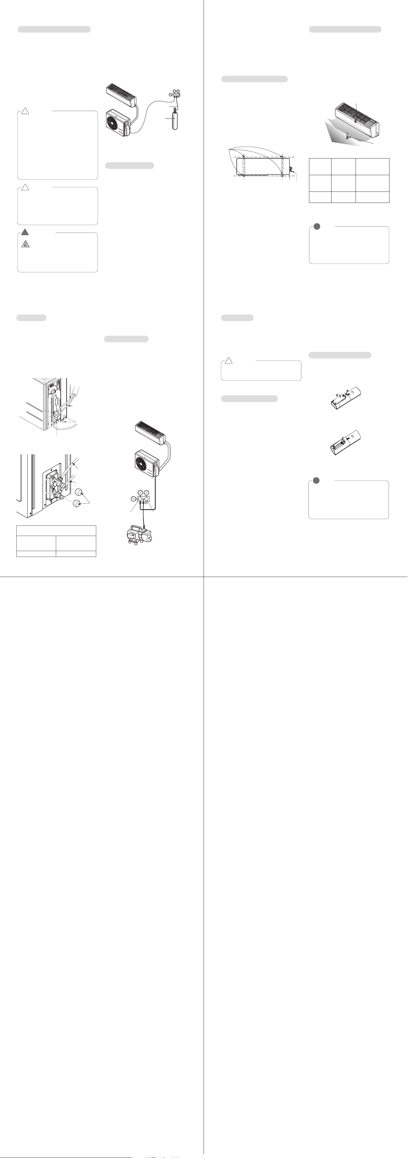
If the outdoor unit is to be installed close to
the seaside, direct exposure to the sea wind
should be avoided. Install the outdoor unit on
the opposite side of the sea wind direction.
In case, to install the outdoor unit on the
seaside, set up a windbreak not to be
exposed to the sea wind.
Select a well-drained place.
- It should be strong enough like concrete to
prevent the sea wind from the sea.
- The height and width should be more than
150% of the outdoor unit.
- Keep more than 70 cm of space between
outdoor unit and the windbreak for easy air
flow.
Installation guide at the seaside
CAUTION
- Air conditioners should not be installed
in areas where corrosive gases, such as
acid or alkaline gas, are produced.
- Do not install the product where it could
be exposed to sea wind (salty wind)
directly. It can result corrosion on the
product. Corrosion, particularly on the
condenser and evaporator fins, could
cause product malfunction or inefficient
performance.
- If outdoor unit is installed close to the
seaside, it should avoid direct exposure
to the sea wind. Otherwise it needs
additional anticorrosion treatment on the
heat exchanger.
!
Sea wind
Sea wind
Sea wind
Windbreak
Selecting the location(Outdoor Unit)
NOTE
!
- If you can’t meet above guide line in
the seaside installation, please con-
tact LG Electronics for the additional
anticorrosion.
- Periodic ( more than once/year )
cleaning of the dust or salt particles
stuck on the heat exchanger by using
water
* Do not use seawater when you
clean up the heat exchanger.
Precautions about installation in regions with extreme snowfall and cold tem-
peratures
To ensure the outdoor unit operates properly, certain measures are required in locations where
there is a possibility of heavy snowfall or severe wind chill or cold :
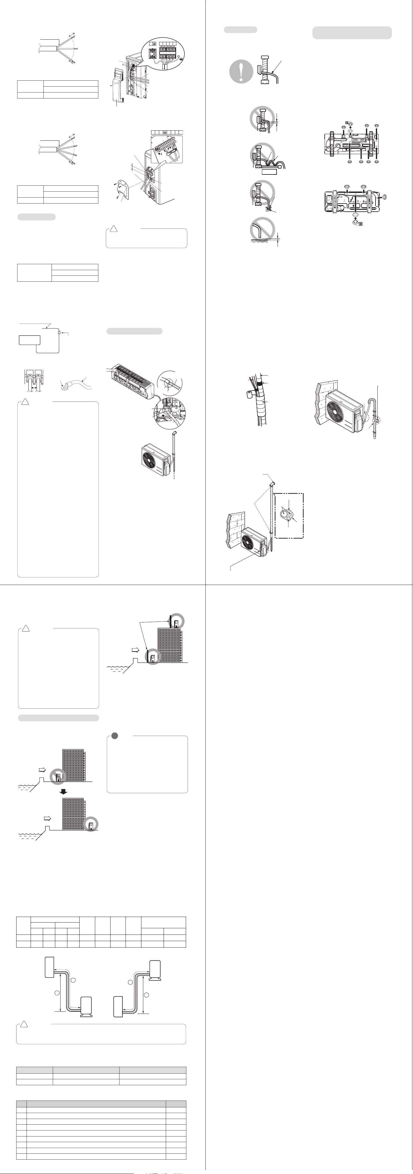
1 Prepare for severe winter wind chills and heavy snowfall, even in areas of the country where
these are unusual phenomena.
2 Position the outdoor unit so that its airflow fans are not buried by direct, heavy snowfall. If
snow piles up and blocks the airflow, the system may malfunction.
3 Remove any snow that has accumulated 4 inches (100mm) or more on the top of the outdoor
unit.
4 Place the outdoor unit on a raised platform at least 20 inches (500mm) higher than the aver-
age annual snowfall for the area. If the frame width is wider than the outdoor unit, snow may
accumulate.
5 Install a snow protection hood.
6 To prevent snow and heavy rain from entering the outdoor unit, install the suction and dis-
charge ducts facing away from direct winds.
7 Additionally, the following conditions should be taken into consideration when the unit oper-
ates in defrost mode:
- If the outdoor unit is installed in a highly humid environment (near an ocean, lake, etc.), en-
sure that the site is well-ventilated and has a lot of natural light. (Example: Install on a
rooftop.)
Outdoor unit
Indoor unit
A
B
Outdoor unit
Indoor unit
A
B
CAUTION
Capacity is based on standard length and maximum allowable length is on the basis of
reliability. Additional refrigerant must be charged after 7.5m(24.6ft).
!
Piping Length and Elevation
Operation ranges
Mode Indoor temperature Outdoor temperature
Cooling 64°F ~ 90°F (18°C ~ 32°C) 14°F ~ 118°F (-10°C ~ 48°C)
Heating 61°F ~ 86°F (16°C ~ 30°C) 14°F ~ 75°F (-10°C ~ 24°C)
The table below indicates the temperature ranges the air conditioner can be Operated within.
Capacity
(Btu/h)
Pipe Size
Standard
Length
m(ft)
Max.
Elevation
Ⓑ m(ft)
Min
Length
Ⓐ m(ft)
Max.
Length
Ⓐ m(ft)
Additional Refrigerant for
longer than 7.5m(24.6ft)
GAS LIQUID
mm inch mm inch g/m oz/ft
18k Ø12.7 1/2 Ø6.35 1/4 7.5(24.6) 10(32.8) - 20(65.6) 30 0.33
24k Ø15.88 5/8 Ø6.35 1/4 7.5(24.6) 10(32.8) - 20(65.6) 30 0.33
Check test items
Test Items Check
1 Indoor unit is hooked to the installation plate properly.
2 The gas and liquid service valves are fully opened.
3 There is no refrigerant gas leakage.
4 System is properly grounded.(No electrical leakage)
5 The connection cable is clamped firmly.
6 Indoor unit receives remote control commands and operates properly.
7 Cooling/Heating operation is normal.
8 There is no abnormal sound.
9 There is no water leakage.
98 10 11
1312 14 15
- Note (Memo) -
MFL67647124(영영) 2016. 7. 15. 영영 1:26 Page 2
CAUTION
Provide the circuit breaker between
power source and the unit as shown by
!
10±3mm
20mm
GN/YL
AWG_“A”
10±3mm
20mm
GN/YL
AWG_“B”
The power connecting cable connected to the
indoor and outdoor unit should be complied
with the following specifications (UL
recognized or CSA certified).
Connecting
Cable
Capacity(Btu/h)
18/24k
"B" 18
Power
Capacity(Btu/h)
18/24k
"A" 14
Connecting cable
Power supply cable
Outdoor unit
- Connect the wires to the terminals on the
control board individually.
- Secure the cable onto the control board with
the cord clamp.
- Use a recognized circuit breaker between
the power source and the unit.
A disconnecting device to adequately
disconnect all supply lines must be fitted.
* Features may change according to the type
of model.
Circuit Breaker(A)
Capacity(Btu/h)
18/24k
20
<18k>
Terminal block
Conduit panel
Tubing cover
Over 5mm
(0.2")
Power supply cord
Connecting cable
1(L1) 2(L2) 1(L1) 2(L2) 3
1(L1) 2(L2) 1(L1) 2(L2)
3
<24k>
Outdoor unit
Terminal block
Over 5mm
(0.2")
Cover control
Conduit panel
Connecting
cable
Power supply
cord
1(L1) 2(L2) 1(L1) 2(L2)
3
2 Do not make drain piping like the following.
* Features may change according to the type
of model.
1 The drain hose should point downward for
easy drain flow.
Do not raise
Water
leakage
Accumulated
drain water
Air
Waving
Water
leakage
Tip of drain hose
dipped in water
Water
leakage
Ditch
Less than
50mm gap
Drain piping
Downward slope
Depending on installation site, it may be re-
quired to install drain plug for drainage(Sup-
plied with the unit). In cold areas, do not use a
drain hose With the outdoor unit. Otherwise,
drain water may freeze, impairing the heating
performance.
1 See the figure below for installation of the
drain plug.
A : Drain connection B : Drain cap
C : Drain washer
2 Connect a field supplied vinyl hose to the
drain connection (A). If the hose is too long
and hangs down, fix it carefully to prevent
kinks.
<18k>
<24k>
Installing drain piping of the
outdoor unit
B B B B
B
B
B
A
C
A
C
BB
B
* Features may change according to the type
of model.
* The provided parts may change according to
the type of model
- Do a leak test of all joints of the tubing(both
indoor and outdoor) and both gas and liquid
side service valves.
Bubbles indicate a leak. Be sure to wipe off
the soap with a clean cloth.
- After the system is found to be free of leaks,
relieve the nitrogen pressure by loosening
the charge hose connector at the nitrogen
cylinder. When the system pressure is
reduced to normal, disconnect the hose from
the cylinder.
* Features may change according to the type
of model.
- Remove the caps from the 2-way and 3-way
valves.
- Remove the service-port cap from the 3-way
valve.
- Apply a soap water or a liquid neutral deter-
gent on the indoor unit connection or out-
door unit connections by a soft brush to
check for leakage of the connecting points of
the piping.
- If bubbles come out, the pipes have leakage
Lo Hi
Outdoor unit
Manifold valv
e
Charge hose
Nitrogen gas
cylinder (in vertical
standing position)
Pressure gauge
Indoor unit
Soap water method
- Preparation
Check that each tube(both liquid and gas
side tubes) between the indoor and outdoor
units have been properly connected and all
wiring for the test run has been completed.
Remove the service valve caps from both
the gas and the liquid side on the outdoor
unit. Note that both the liquid and the gas
side service valves on the outdoor unit are
kept closed at this stage.
- Leak test
Connect the manifold valve(with pressure
gauges) and dry nitrogen gas cylinder to this
service port with charge hoses.
Air purging with vacuum pump
CAUTION
Be sure to use a manifold valve for air
purging. If it is not available, use a stop
valve for this purpose. The knob of the
3-way valve must always be kept close.
- Pressurize the system to maximum
250 P.S.I.G. (17.6 kgf/cm
2
G) (R-22
model) or 400 P.S.I.G. (28.1 kgf/cm
2
G)
(R-410A model) with dry nitrogen gas
and close the cylinder valve when the
gauge reading reaches 250 P.S.I.G.
(17.6 kgf/cm
2
G) (R-22 model) or 400
P.S.I.G. (28.1 kgf/cm
2
G) (R-410A model).
Next step is leak test with liquid soap.
!
CAUTION
To avoid nitrogen entering the refrigerant
system in a liquid state, the top of the
cylinder must be higher than its bottom
when you pressurize the system. Usually,
the cylinder is used in a vertical standing
position.
!
WARNING
!
There is a risk of fire and explosion.
Inert gas (nitrogen) should be used
when you check plumbing leaks, cleaning
or repairs of pipes etc.
If you are using combustible gases
including oxygen, product may have the
risk of fires and explosions.
Operate the unit for 15~20 minutes, then
check the system refrigerant charge:
- Measure the pressure of the gas side serv-
ice valve.
- Measure the air temperature from inlet and
outlet of air conditiioner.
- Ensure the difference between the inlet and
outlet temperature is more than 14.4°F (8°C).
- For reference; the gas side pressure at opti-
mum condition is shown on table (cooling)
The air conditioner is now ready to use.
* Features may change according to the type
of model.
Discharge
temperature
Discharge air
Inlet temperature
NOTE
!
If the actual pressure is higher than
shown, the system is most likely over-
charged, and charge should be removed.
If the actual pressure are lower than
shown, the system is most likely under-
charged, and charge should be added.
Evaluation of the performance
Refrigerant
Outside
ambient
TEMP.
The pressure of
the gas
side service valve.
R-22 35°C (95°F)
4~5kg/cm
2
G
(56.8~71.0
P.S.I.G.)
R-410A 35°C (95°F)
8.5~9.5kg/cm
2
G
(120~135 P.S.I.G.)
- Replace the valve caps at both gas and liquid
side service valves and fasten them tight.
This completes air purging with a vacuum pump.
- Replace the pipe cover to the outdoor unit by
one screw
Now the air conditioner is ready for test run.
* The feature can be changed according to the
type of model.
- Fix the outdoor unit with a bolt and
nut(ø10mm) tightly and horizontally on a con-
crete or rigid mount.
- When installing on the wall, roof or rooftop,
anchor the mounting base securely with a
nail or wire assuming the influence of wind
and earthquake.
- If the vibration of the unit is transmitted to
the pipe, secure the unit with an anti-vibra-
tion rubber.
Settlement of outdoor unit
Bolt
Tubing connection
* Features may change according to the type
of model.
Checking the Drainage
1 Pour a glass of water on the evaporator.
2 Ensure the water flows through the drain
hose of the indoor unit without any leak-
age and goes out the drain exit.
To check the drainage.
Drain Pan
Drain
Hose
Leakage
Checking
Connecting area
drain hose
Leakage
checking
CAUTION
According to the confirmation of the above
conditions, prepare the wiring as follows.
1 Never fail to have an individual power cir-
cuit specifically for the air conditioner. As
for the method of wiring, be guided by the
circuit diagram posted on the inside of con-
trol cover.
2 The screw which fasten the wiring in the
casing of electrical fittings are liable to
become loose from vibrations to which the
unit is subjected during the transportation.
Check them and make sure that They all
are tightly fastened. (If they are loose, it
could cause burn-out of the wires.)
3 Specification of power source.
4 Confirm that electrical capacity is sufficient.
5 See that the starting voltage is maintained
at more than 90 percent of the rated volt-
age marked on the name plate.
6 Confirm that the cable thickness is as spec-
ified in the power source specification.
(Particularly note the relation between cable
length and thickness.
7 Always install an earth leakage circuit
breaker in a wet or moist area.
8 The following would be caused by voltage
drop.
- Vibration of a magnetic switch, which will
damage the contact point, fuse breaking,
disturbance of the normal function of the
overload.
9 The means for disconnection from a power
supply shall be incorporated in the fixed
wiring and have an air gap contact separa-
tion of at least 3mm in each active(phase)
conductors.
!
Air
Conditioner
Main power source
Circuit Breaker
Use a circuit breake or time
delay fuse.
Over
5mm
Round pressure
terminal
Power wire
Round Pressure terminal and connecting
requirement.
In cases where the outdoor unit is installed
above the Indoor unit perform the following.
1 Tape the piping and connecting cable from
down to up.
2 Secure the taped piping along the exterior
wall. Form a trap to prevent water entering
the room.
3 Fix the piping onto the wall using saddle or
equivalent
Air Purging
The air and moisture remaining in the refriger-
ant system have undesirable effects as indi-
cated below.
- Pressure in the system rises.
- Operating current rises.
- Cooling(or heating) efficiency drops.
- Moisture in the refrigerant circuit may freeze
and block capillary tubing.
- Water may lead to corrosion of parts in the
refrigeration system.
Therefore, after evacuating the system, take a
leak test for the piping and tubing between
the indoor and outdoor unit.
Seal a small opening
around the pipings
with gum type sealant.
Trap
Trap
Forming of the Piping
Form the piping by wrapping the connecting
portion of the indoor unit with insulation
material and secure it with two kinds of vinyl
tapes.
- If you want to connect an additional drain
hose, the end of the drain outlet should be
routed above the ground. Secure the drain
hose appropriately.
In cases, where the outdoor unit is installed
below the Indoor unit, perform the following.
1 Tape the piping, drain hose and connecting
cable from down to up.
2 Secure the tapped piping along the exterior
wall using saddle or equivalent.
In cases, where the outdoor unit is installed
above the Indoor unit, perform the following.
Taping
Saddle
Drain hose
Pipings
Connecting cable
Seal small openings
around pipings with a
gum type sealant.
Trap is required to prevent water
from entering into electrical parts.
Drain hose
Vinyl tape(narrow)
Pipe
Wrap with
vinyl tape(wide)
- With a service valve wrench, turn the valve of
liquid side counter-clockwise to fully open the
valve
- Turn the valve of gas side counter clockwise to
fully open the valve
- Loosen the charge hose connected to the gas
side service port slightly to release the pressure,
then remove the hose.
- Replace the flare nut and its bonnet on the gas
side service port and fasten the flare nut secure-
ly with an adjustable wrench. This process is
very important to prevent leakage from the sys-
tem.
Outdoor unit
Lo Hi
Manifold valve
Vacuum pump
Pressure
gauge
Open
Close
Indoor unit
Finishing the Job
- Connect the charge hose end described in
the preceding steps to the vacuum pump to
evacuate the tubing and indoor unit.
Confirm the "Lo" knob of the pressure Gauge
is open. Then, run the vacuum pump.
The operation time for evacuation varies with
tubing length and capacity of the pump. The
following table shows the time required for
Evacuation.
- When the desired vacuum is reached, close
the knob of the 3-way valve and stop the
vacuum pump.
Evacuation
Required time for Evacuation when 30 gal/h
vacuum pump is used
If tubing length is
less than 10m (33 ft)
If tubing length is
longer than 10m
(33 ft)
10 min. or more 15 min. or more
<18k>
Cap
Gas side
3-way valve
3-way valve
(Close)(Close)
3-way valve
(Close)
2-way valve
(Close)
Liquid side
<24k>
Outdoor unit
Gas side
Liquid side
Cap
2-way valve(Close)
2-way valve(Close)
3-way valve(Close)3-way valve(Close)
2-way valve(Close)
3-way valve(Close)
Prepare remote controller
Test Running
- Check that all tubing and wiring are properly
connected.
- Check that the gas and liquid side service
valves are fully open.
Insert batteries before using the remote con-
trol. The battery type used is AAA (1.5 V).
1 Remove the battery cover by pulling it
according to the arrow direction.
2 Insert new batteries making sure that the
(+) and (–) of battery are installed correctly.
3 Reattach the cover by pushing it back into
position.
NOTE
!
• Use 2 AAA(1.5volt) batteries. Do not use
rechargeable batteries.
• Remove the batteries from the remote
controller if the system is not used for a
long time
This is performed when the unit is relocated
or the refrigerant circuit is serviced.
Pump Down means collecting all refrigerant
into the outdoor unit without the loss of refrig-
erant.
- Connect a low-pressure gauge manifold hose
to the charge port on the gas side service
valve.
- Open the gas side service valve halfway and
purge the air in the manifold hose using the
refrigerant.
- Close the liquid side service valve(all the
way).
- Turn on the unit's operating switch and start
the cooling operation.
- When the low-pressure gauge reading
becomes 1 to 0.5kg/cm
2
G(14.2 to 7.1
P.S.I.G.), fully close the gas side valve and
then quickly turn off the unit. Now Pump
Down procedure is completed, and all refrig-
erant is collected into the outdoor unit.
CAUTION
Be sure to perform Pump Down proce-
dure in the cooling mode.
!
Pump Down Procedure
Pump down
If the outdoor unit is to be installed close to
the seaside, direct exposure to the sea wind
should be avoided. Install the outdoor unit on
the opposite side of the sea wind direction.
In case, to install the outdoor unit on the
seaside, set up a windbreak not to be
exposed to the sea wind.
Select a well-drained place.
- It should be strong enough like concrete to
prevent the sea wind from the sea.
- The height and width should be more than
150% of the outdoor unit.
- Keep more than 70 cm of space between
outdoor unit and the windbreak for easy air
flow.
Installation guide at the seaside
CAUTION
- Air conditioners should not be installed
in areas where corrosive gases, such as
acid or alkaline gas, are produced.
- Do not install the product where it could
be exposed to sea wind (salty wind)
directly. It can result corrosion on the
product. Corrosion, particularly on the
condenser and evaporator fins, could
cause product malfunction or inefficient
performance.
- If outdoor unit is installed close to the
seaside, it should avoid direct exposure
to the sea wind. Otherwise it needs
additional anticorrosion treatment on the
heat exchanger.
!
Sea wind
Sea wind
Sea wind
Windbreak
Selecting the location(Outdoor Unit)
NOTE
!
- If you can’t meet above guide line in
the seaside installation, please con-
tact LG Electronics for the additional
anticorrosion.
- Periodic ( more than once/year )
cleaning of the dust or salt particles
stuck on the heat exchanger by using
water
* Do not use seawater when you
clean up the heat exchanger.
Precautions about installation in regions with extreme snowfall and cold tem-
peratures
To ensure the outdoor unit operates properly, certain measures are required in locations where
there is a possibility of heavy snowfall or severe wind chill or cold :
1 Prepare for severe winter wind chills and heavy snowfall, even in areas of the country where
these are unusual phenomena.
2 Position the outdoor unit so that its airflow fans are not buried by direct, heavy snowfall. If
snow piles up and blocks the airflow, the system may malfunction.
3 Remove any snow that has accumulated 4 inches (100mm) or more on the top of the outdoor
unit.
4 Place the outdoor unit on a raised platform at least 20 inches (500mm) higher than the aver-
age annual snowfall for the area. If the frame width is wider than the outdoor unit, snow may
accumulate.
5 Install a snow protection hood.
6 To prevent snow and heavy rain from entering the outdoor unit, install the suction and dis-
charge ducts facing away from direct winds.
7 Additionally, the following conditions should be taken into consideration when the unit oper-
ates in defrost mode:
- If the outdoor unit is installed in a highly humid environment (near an ocean, lake, etc.), en-
sure that the site is well-ventilated and has a lot of natural light. (Example: Install on a
rooftop.)
Outdoor unit
Indoor unit
A
B
Outdoor unit
Indoor unit
A
B
CAUTION
Capacity is based on standard length and maximum allowable length is on the basis of
reliability. Additional refrigerant must be charged after 7.5m(24.6ft).
!
Piping Length and Elevation
Operation ranges
Mode Indoor temperature Outdoor temperature
Cooling 64°F ~ 90°F (18°C ~ 32°C) 14°F ~ 118°F (-10°C ~ 48°C)
Heating 61°F ~ 86°F (16°C ~ 30°C) 14°F ~ 75°F (-10°C ~ 24°C)
The table below indicates the temperature ranges the air conditioner can be Operated within.
Capacity
(Btu/h)
Pipe Size
Standard
Length
m(ft)
Max.
Elevation
Ⓑ m(ft)
Min
Length
Ⓐ m(ft)
Max.
Length
Ⓐ m(ft)
Additional Refrigerant for
longer than 7.5m(24.6ft)
GAS LIQUID
mm inch mm inch g/m oz/ft
18k Ø12.7 1/2 Ø6.35 1/4 7.5(24.6) 10(32.8) - 20(65.6) 30 0.33
24k Ø15.88 5/8 Ø6.35 1/4 7.5(24.6) 10(32.8) - 20(65.6) 30 0.33
Check test items
Test Items Check
1 Indoor unit is hooked to the installation plate properly.
2 The gas and liquid service valves are fully opened.
3 There is no refrigerant gas leakage.
4 System is properly grounded.(No electrical leakage)
5 The connection cable is clamped firmly.
6 Indoor unit receives remote control commands and operates properly.
7 Cooling/Heating operation is normal.
8 There is no abnormal sound.
9 There is no water leakage.
98 10 11
1312 14 15
- Note (Memo) -
MFL67647124(영영) 2016. 7. 15. 영영 1:26 Page 2