Loading ...
Loading ...
Loading ...
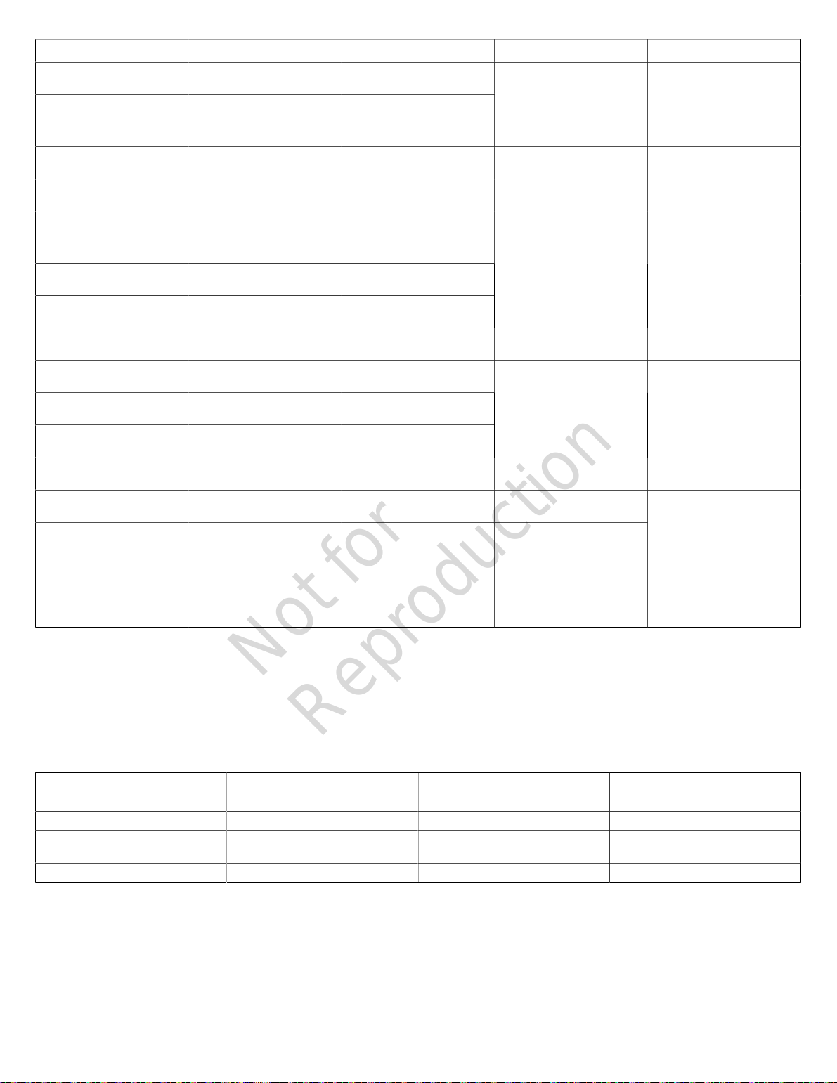
Pin Number Description Wire Type Connect To Notes
4 2-WIRE START 18AWG[1mm
2
] conductors,
600V minimum, 90°C Cu wire
5 2-WIRE START 18AWG[1mm
2
] conductors,
600V minimum, 90°C Cu wire
Refer to Transfer switch
manual to verify if this function
is available
Contact Close for Genset
Start. (Only for transfer
switch that provides this
option). Mains monitoring
must be disabled in the
controller
6 E-STOP 18AWG[1mm
2
] conductors,
600V minimum, 90°C Cu wire
E-Stop Switch
7 E-STOP 18AWG[1mm
2
] conductors,
600V minimum, 90°C Cu wire
E-Stop Switch
Contact Open to Shutdown
Genset
8 Not Used - - -
9 VIN+
(+12V)
18AWG[1mm
2
] conductors,
600V minimum, 90°C Cu wire
10 D- 18AWG[1mm
2
] conductors,
600V minimum, 90°C Cu wire
11 D+ 18AWG[1mm
2
] conductors,
600V minimum, 90°C Cu wire
12 GND 18AWG[1mm
2
] conductors,
600V minimum, 90°C Cu wire
Refer to the Amplify Gateway
Manual
Comm to WIFI module
Twisted pair #1: +12V and
GND
Twisted pair #2: (D-) and (D+)
13 +12V 18AWG[1mm
2
] conductors,
600V minimum, 90°C Cu wire
14 (B) 18AWG[1mm
2
] conductors,
600V minimum, 90°C Cu wire
15 (A) 18AWG[1mm
2
] conductors,
600V minimum, 90°C Cu wire
16 GND 18AWG[1mm
2
] conductors,
600V minimum, 90°C Cu wire
Not used Not used
25 25 14AWG [2.5mm
2
] 600V
minimum, 90°C Cu Wire
Transfer switch Utility
26 26 14AWG [2.5mm
2
] 600V
minimum, 90°C Cu Wire
Transfer switch Utility
Delivers power to the
generator’s battery charger,
controller, optional battery
warmer, optional oil warmer,
and optional fuel regulator
warmer. Also, when voltage
on these leads is lost in AUTO
Mode, generator will start if
Mains Monitoring is enabled
(default setting)
• For power output connection (L1, L2, Neutral (N), and Ground), refer to the National Electric Code (NEC) and local
codesfor correct wire specifications.
• For communication wires use 600V wire and #18 AWG[1mm
2
]twisted-pair conductors that do not exceed a length of
500 ft (150 m).
• When connecting to the terminal block, fasten only one wire to each connector screw.
• Torque terminal block screws to 4.4 in-lb [0.5Newton meter (N·m)].
Connection Specifications
Connection Temperature Rating: °F (°C) Recommended Wire Size
(AWG)
Torque Specifications
Circuit Breaker(copper or aluminum) 140 °F/ 167 °F(60°C/ 75°C) 6 to1/0 45 in-lbs (5.08 Nm)
Neutral Lug (copper or aluminum) 167°F(75°C) 2/0 to 14 CU
2/0 to 12 AL
120 in-lbs (13.56 Nm)
Ground Lug(copper or aluminum) 194°F(90°C) 14 to2 50 in-lbs (5.65 Nm)
AC System Connections
The generator uses a single-phase, three-wire AC connection
system(Figure 18). The stator assembly consists of a pair
of stationary windings with two leads appearing from each
winding. The junction of leads 22 and 33 forms the neutral
lead.
NOTICE: Neutral is not bonded to ground at generator.
NOTICE: The generator must be used with an UL listed
transfer switch that is compatible with the generator.
Only use the generator with a listed transfer switch that is
compatible with the generator.
20 BRIGGSandSTRATTON.COM
Not for
Reproduction
Loading ...
Loading ...
Loading ...