Loading ...
Loading ...
Loading ...
17
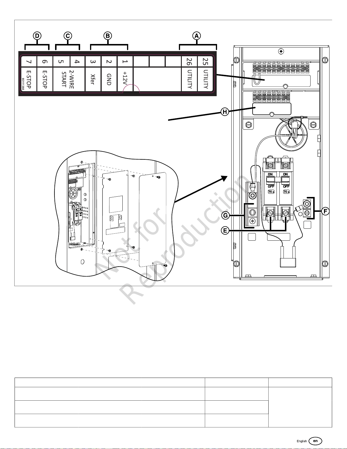
Legend(Figure 17):
• (A)Utility and Field Connections Terminal Block — Connects utility 240 VAC from the fuse block in ATS to the controller.
Connect only one wire per terminal. Reference the table that follows for field connections.
• (B)Transfer Switch Connection — Controls the transfer switch contactor.
• (C)Two-wire Start — Helps provide optional remote start contact.
• (D) E-Stop — Use with the optional external E-Stop
• (E)Power Connection (L1 and L2) — Connects to the transfer switch
• (F)Ground Connection — Connects to the transfer switch ground wire
• (G)Neutral Connection — Connects to the transfer switch neutral wire
• (H)Communications Terminal Block — Reference the table that follows:
Pin Number Description Wire Type Connect To Notes
1 +12V 18AWG[1mm
2
] conductors,
600V minimum, 90°C Cu wire
Transfer switch basic
controller J7-8 12VDC
2 GND 18AWG[1mm
2
] conductors,
600V minimum, 90°C Cu wire
Transfer switch basic
controller J7-7 GND
3 Xfer 18AWG[1mm
2
] conductors,
600V minimum, 90°C Cu wire
Transfer switch basic
controller J7-4 T/R
Transfer switch Transfer
Signal (only works with basic
Transfer Switch Controller
19
Not for
Reproduction
Loading ...
Loading ...
Loading ...