Loading ...
Loading ...
Loading ...
Using the Diagnostic Tool
CODE RETRIEVAL PROCEDURE
Craftsman 87702 35
The Diagnostic Tool will display a code only if codes are present
in the vehicle’s computer memory. If no codes (including
“enhanced” codes) are present, a “No Powertrain DTCs or
Freeze Frame Data is presently stored in the vehicle’s
computer” message is displayed.
The Diagnostic Tool is capable of retrieving and storing up to 32
codes in memory, for immediate or later viewing.
7. To read the display:
Refer to DISPLAY FUNCTIONS on page 9 for a descrip-
tion of LCD display elements.
A visible icon indicates that the Diagnostic Tool is being
powered through the vehicle’s DLC connector.
A visible icon indicates that the Diagnostic Tool is linked to
(communicating with) the vehicle’s computer.
The I/M Monitor Status icons indicate the type and number of
Monitors the vehicle supports, and provides indications of the
current status of the vehicle’s Monitors. A solid Monitor icon
indicates the associated Monitor has run and completed its
testing. A blinking Monitor icon indicates the associated Monitor
has not run and completed its testing.
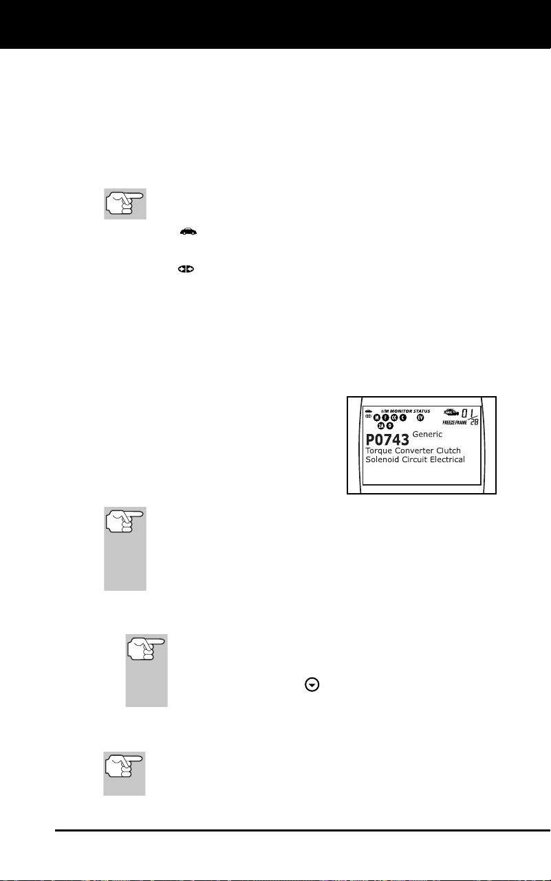
The upper right hand corner of the dis-
play shows the number of the code
currently being displayed, the total
number of codes retrieved, the type of
code and whether or not the displayed
code commanded the MIL on. If the
code being displayed is a PENDING
code, the PENDING icon is shown.
Freeze Frame data is always associated with the “Priority
Code” (identified as Code #1 in the Diagnostic Tool’s display).
If the FREEZE FRAME icon is lit when the “Priority Code”
(Code #1) is displayed on the Diagnostic Tool’s screen, it
indicates that there is Freeze Frame data associated with this
code, and the vehicle’s computer has saved it in its memory.
The Diagnostic Trouble Code (DTC) and related code definition
are shown in the lower section of the LCD display.
In the case of long code definitions, a small arrow is
shown in the upper/lower right-hand corner of the code
display area to indicate the presence of additional
information. Use the
button to view the additional
information.
8. Read and interpret Diagnostic Trouble Codes/system condition
using the LCD display and the green, yellow and red LEDs.
The green, yellow and red LEDs are used (with the LCD
display) as visual aids to make it easier to determine
engine system conditions.
Loading ...
Loading ...
Loading ...